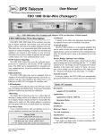
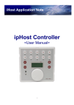
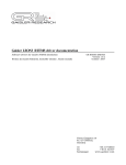
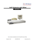
1
DPS Telecom
User Manual
S WAV I n t e r f a c e Pa ck ag e s
Package Description
The SWAV Interface package is available in several
configurations for interfacing Order-Wire voice and
alarm system data to a the VF ports of a SONET network
using NEC SpectralWave terminals.
Fig. 1 - FDO 1000 Order-Wire Terminal with SWAV interfaces SONET network via NEC SpectralWave.
low the desired party's name to be announced over the
speaker.
FDO 1000 Order-Wire Description
With DPS' FDO 1000 Order-Wire terminal, your analog or digital network can become your own private
phone system, with links to the public telephone network.
The order-wire is an economical party-line system that
requires no central switching. An order-wire terminal and
telephone are located at each facility in your network. The
order-wire system is simple to operate and can significantly reduce your voice communications costs.
DTMF Selective Signaling
The DPS FDO Order-Wire uses the on-board microprocessor to synthesize and decode DTMF signaling
tones. The FDO can be programmed for automatic privacy, manual privacy, no privacy and hoot-n-holler operating modes.
LED Indicators
Front panel LEDs indicate order-wire off-hook, incoming call ringing and channel busy. Front panel test points
and level controls are provided for calibration.
Addressing
The Order-Wire responds to one, two or three digit addressing. Leading zeroes in the address will set it for one
or two digits. Rotary switches on the P.C. Board allow the
address to be easily set. The station address is posted on
the front panel with stick-on labels (labels are included).
Four-Wire Phone
Voice communications and out-dialing occur at a
4-wire telephone, mounted near the order-wire.
Call Buzzer
A buzzer in the order-wire announces incoming calls.
An optional buzzer can be installed in the phone.
External speaker
The FDO 1000 includes a 2-watt speaker amplifier that
can be used to drive an external eight ohm speaker. A paging feature can be activated from any calling station to al-
Passive Bridge, Optional Active Bridge.
The FDO 1000 is facility-ready, with a built-in 4-Way
passive bridge and level matching pads for +7 / -16 dBm
channel levels. The bridge can also be bypassed for direct
interface at the order-wire's active VF ports. An accessory
active bridge can be installed on the order-wire's P.C.
board for matching levels other than +7/-16 dBm.
Network Control
In privacy modes, the FDO 1000 uses automatically
generated DTMF tones to control access to the order-wire
network. An off-hook tone is generated when a caller
picks up the phone, which causes other stations on the
network to assume a busy state. If any other phone is
picked up during the busy state, a busy signal will
sound in the earpiece. Busied stations remain in that state
until their station code is dialed from the caller's phone or
until the caller hangs up, generating an on-hook tone.
Table of Contents
Description . . . . . . . . . . . . . . . . . . . . . . . . . . . . . . . . . . . . . 1
SWAV Interface . . . . . . . . . . . . . . . . . . . . . . . . . . . . . . 2
Applications . . . . . . . . . . . . . . . . . . . . . . . . . . . . . . . . . . . . 3
Order-wire packages with the SWAV . . . . . . . . . . . . 3
Operation Modes. . . . . . . . . . . . . . . . . . . . . . . . . . . . . 4
Shipping List. . . . . . . . . . . . . . . . . . . . . . . . . . . . . . . . . . . . 8
Installation . . . . . . . . . . . . . . . . . . . . . . . . . . . . . . . . . . . . . 8
Reference Figures. . . . . . . . . . . . . . . . . . . . . . . . . . . . . . . . 8
Test and Acceptance. . . . . . . . . . . . . . . . . . . . . . . . . . . . . 18
Specifications . . . . . . . . . . . . . . . . . . . . . . . . . . . . . . . . . . 20
Change Notice
FDO 1000-11A-0V/SWAV
November 22,1999
Options and Model Numbers . . . . . . . . . . . . . . . . . . . . . 20
1
UM119789
Fig. 3 - Accessories for Order-Wire include active
4w/4w bridge, 4-wire DTMF phone and speaker.
SWAV
The SWAV Interface card fits in the expansion card slot
of the order-wire chassis. It joins the order-wire terminal
to the network with an auxiliary port for an off-net connection. It also provides a separate VF channel for alarm
system data. The SWAV front panel includes test jacks
and level controls to monitor equipment.
Fig. 2 - Order-wire packages include external speaker,
phone, SWAV and rack-mount housing.
Wire-Wrap and Connectorized Back Panel
All network, power and auxiliary connections are made
at wire-wrap blocks and connectors on the back panel. An
RJ-12 jack is provided for the phone and screw-terminal
barriers are provided for the power (office battery).
voice input/output, bridge port connections, fuse alarm,
external buzzer, speaker and M lead connections are all
provided on a 60 pin wire-wrap block.
Applications
The SWAV Interface is available in application packages
that include FDO 1000 Order-Wire with KDA alarm network elements and the FDO 3000 Off-Net.
FDO1000 Order-Wire
Order-Wire
Electronics
FDO1000 Order-Wire
To alarm network
or element
Speaker
SWAV
SWAV
VF
Ports
Order-Wire
Electronics
Speaker
VF
Ports
4-Wire
Phone
4-Wire
Phone
To alarm network
or element
Digital
Network
FDO1000 Order-Wire
Order-Wire
Electronics
FDO1000 Order-Wire
SWAV
VF
Ports
VF
Ports
Speaker
4-Wire
Phone
SWAV
To alarm network
or element
To alarm network
or element
POTS Line
to PSTN
Order-Wire
Electronics
Speaker
4-Wire
Phone
FDO 3000 Off-Net
Fig. 4 - A typical analog order-wire network provides voice communications between telecom sites
and to the Public Switched Telephone Network (PSTN) via a Plain-Old Telephone Service (POTS) line.
UM119789
2
FDO 1000-11A-0V/SWAV
November 22, 1999
OA
ILAMP 1
Terminal
Terminal
ILAMP 3
ILAMP 2
OW Chan.
OW Chan.
BR
SWAV
BR
BR
FDO 1000 Order-Wire
FDO 3000 Off-Net
To E2A
Polling
Unit
or Remote
Off-net
Phone
Line
BR
SWAV
BR
BR
SWAV
FDO 1000
Order-Wire
KDA 864 E2A
SWAV
FDO 1000 Order-Wire
FDO 3000 Off-Net
BR
BR
SWAV
BR
FDO 1000
Order-Wire
FDO 1000
Order-Wire
BR
To E2A
Polling
Unit
Off-net
Phone
Line
KDA 864 E2A
KDA 864 E2A
Fig. 5 - SWAV packages equipped with the Order-Wire interface voice and data to the VF supervisory ports of an
NEC SpectralWave SONET terminal. (Also see Fig. 21.).
DTMF Selective Signaling
Fig. 2 shows the basic components of the order-wire.
Station call codes are programmed manually with rotary switches on the order-wire P.C. board. Number labels
are provided to place on the front panel to indicate the setting.
Each site should be equipped with a 4-Wire DTMF
phone and external speaker.
Wire-Wrap Jumpers
To utilize the order-wire's four-way bridge or the
SWAV, jumpers must be installed at the wire-wrap block.
When the application details are known at the time an order is placed, these jumpers will be factory installed.
In its simplest configuration, the SWAV card is available in an otherwise unpopulated shelf.
Blank
Order-Wire
KDA network element
The FDO 1000 Order-Wire with SWAV can be combined with a DPS KDA-E2A equipped with a Scan 4
four-port TBOS scanner to make a “satellite terminal” to
provide a voice and discrete/TBOS alarm E2A/VF interface to SONET. (Figs. 5, 8, and 23).
Order-Wire
SWAV
Fig. 9 - SWAV Order-Wire expansion package.
SWAV
An expansion package is available to add an order-wire
to a site with an existing KDA network element. (Fig. 9)
The FDO 1000 Order-Wire with SWAV can be combined
with an FDO 3000 Off-Net to make a "terminal order-wire
Order-Wire Packages with the SWAV
Order-Wire
The FDO 1000 Order-Wire with SWAV can be combined with a DPS KDA 864-E2A network element for
alarm applications via SONET. (Figs. 5, 7, 22 and 24)
KDA network element
Scan 4
Fig. 8 - SWAV Satellite KDA E2A/Scan 4 package.
Fig. 6 - Basic SWAV package.
Order-Wire
SWAV
Off-Net
SWAV
Blank
SWAV
Fig. 10 - SWAV Order-Wire Off-Net package.
Blank
with off-net" for interfacing voice and a PSTN connection to
SONET. The expansion card is not used in off-net for this
application.)
Fig. 7 -SWAV Satellite KDA E2A package.
FDO 1000-11A-0V/SWAV
November 22,1999
3
UM119789
Automatic Privacy
1. Off Hook
Dial Tone
Busy Tone
Muted
Busy
222
Muted
Off Hook
111
Off Hook
Tone (#)
Muted
Busy
Voice
Facility
333
Muted
Busy
444
2. Dial Station Code
DTMF Tones
(side tone)
Muted
Off Hook
333
Voice
Facility
Dial Code
Muted
Buzzer
Ring
333
Muted
Busy
444
3 3 3
Busy Tone
Muted
2a. Alternate dial w/page (8 + station code)
Busy
222
Muted
Off Hook
111
8333
Voice
Facility
Dial Code
Joe
Smith!
Ring
333
Muted
Busy
444
8 3 3 3
3. Call Answered
Off hook tone
Talk
Busy Tone
222
Muted
111
DTMF Tones
(side tone)
Busy
Muted
Busy Tone
Muted
Off Hook
Off Hook Tone (#)
111
Busy
222
Voice
Facility
Muted
Off Hook
Talk
333
Muted
Busy
444
4. Call Terminated (system normal)
Unmuted
111
Unmuted
222
On Hook
Tone (*)
On Hook
Tone (*)
Voice
Facility
Unmuted
333
Unmuted
444
Fig. 11 - Order of operation in the automatic privacy mode.
Operation Modes
speakers are muted. Either party hanging up generates an
“on-hook” tone to clear the busy state.
In this mode the calling party may page the desired
party over the called station's speaker by dialing “8” prior
to entering the three-digit station code.
NOTE: Avoid using station codes starting with “8.”
The busy state may be manually cleared by pressing the
“*” button. It can be restored by pressing the “#” button.
Other parties can be added to the conversation at any
time.
Automatic Privacy
Refer to Fig. 11. In the automatic privacy mode the
FDO order-wire performs like a normal private line telephone. The caller hears dial tone when the phone is first
taken off hook and an “off-hook” tone is broadcast to
busy out the network. When the caller dials the three-digit
code for a station, the buzzer at that station sounds and the
caller hears a ring-back tone. When the called party answers, the ring-back and buzzer are silenced and conversation may proceed. During the conversation all other stations will hear a busy signal in the handset and all monitor
UM119789
4
FDO 1000-11A-0V/SWAV
November 22, 1999
Manual Privacy
1. Off Hook
222
Muted
Dial Tone
Unmuted
Off Hook
Voice
Facility
111
Unmuted
333
Unmuted
444
2. Dial Station Code
DTMF Tones
(side tone)
Unmuted
222
Muted
Off Hook
111
3 3 3
333
Voice
Facility
333
Unmuted
444
Dial Code
3. Call Answered
Talk
Unmuted
Buzzer
Ring
Unmuted
222
Muted
Off Hook
Talk
111
Voice
Facility
Muted
Off Hook
Talk
Off Hook
Talk
333
Unmuted
444
3. Invoking Privacy
Press #
Muted
Busy
Busy Tone
222
Muted
Off Hook
#
111
Voice
Facility
#
Muted
333
Muted
Busy
444
4. Call Terminated (system normal)
Unmuted
111
Unmuted
222
On Hook
Tone (*)
On Hook
Tone (*)
Voice
Facility
Unmuted
333
Unmuted
444
Fig. 12 - Order of operation in the manual privacy mode.
An “all call” code rings all stations. Unanswered stations will time out in 90 seconds.
Manual Privacy
Refer to Fig. 12. The manual privacy mode works like
the automatic privacy mode, except that the caller must
press the “#” key to establish the busy state. It is released
by dialing a “*” or by hanging up the phone.
FDO 1000-11A-0V/SWAV
November 22,1999
5
UM119789
No Privacy
1. Off Hook
Unmuted
222
Muted
Dial Tone
Off Hook
Voice
Facility
111
Unmuted
333
Unmuted
444
2. Dial Station Code
DTMF Tones
(side tone)
222
Muted
Off Hook
111
3 3 3
Unmuted
333
Voice
Facility
Dial Code
333
Unmuted
444
3. Call Answered
Talk
Unmuted
Buzzer
Ring
Unmuted
222
Muted
Off Hook
111
Talk
Muted
Talk
Voice
Facility
Off Hook
Talk
333
Unmuted
444
4. Group Conversation
Talk
Muted
Off Hook
Talk
222
Muted
Off Hook
111
NOTE: Station code does not
have to be dialed to enter conversation.
Muted
Voice
Facility
Off Hook
Talk
333
Unmuted
444
5. Call Terminated (system normal)
222
Unmuted
111
Unmuted
Voice
Facility
Unmuted
333
Unmuted
444
Fig. 13 - Order of operation in the no privacy mode.
No Privacy
Refer to Fig. 13. In the no privacy mode monitor speakers
remain on when the system is in use and any station may get
on the system at any time. A station's monitor speaker mutes
only when the station phone is taken off hook.
UM119789
6
FDO 1000-11A-0V/SWAV
November 22,1999
1. Off Hook
Hoot-n-Holler
Unmuted
Muted
Unmuted
Off Hook
Voice
Facility
Unmuted
2. Call name of party or station
Hey, Joe!
Hey, Joe!
222
Muted
Off Hook
Voice
Facility
111
Hey, Joe!
333
Hey, Joe!
444
3. Call Answered
Talk
Unmuted
222
Muted
Off Hook
111
Talk
Muted
Talk
Voice
Facility
Off Hook
Talk
333
Unmuted
444
4. Group Conversation
Talk
Muted
Off Hook
222
Muted
Off Hook
111
Voice
Facility
Talk
NOTE: Station code does not have
to be dialed to enter conversation.
Muted
Off Hook
Talk
333
Unmuted
444
5. Call Terminated (system normal)
222
Unmuted
111
Unmuted
Voice
Facility
Unmuted
333
Unmuted
444
Fig. 14 - Order of operation in the hoot-n-holler mode.
Hoot-n-Holler
Refer to Fig. 14. A 4-wire telephone and an external
s p e a ke r c a n t u r n t h e F D O 1 0 0 0 i n t o a c l a s s i c
“hoot-n-holler” order-wire. The speaker should be located where it can be heard by all parties at a facility. The
phone is used to announce the desired party over the monitor speakers. When the person answers, the speaker is
muted. All other sites continue to monitor the order-wire
channel over the speakers. This application can use the
FDO-1301 phone and FDO-1200 speaker.
FDO 1000-11A-0V/SWAV
November 22,1999
7
UM119789
NOTE: Speaker ground (SG)
is at -Batt. potential.
Do not ground it to
frame or other equipment.
1 2 3 4 5 6 7 8 9 10
On/Off Hook Function
The factory default uses # and * tones for controlling
privacy functions. In cases where these tones are already
in use for other functions, switch SW5-3 can be set ON to
change control to the fourth column “A” and “C” tones.
(The fourth column buttons are not provided on the
phone, so manual privacy will not work if SW5-3 is ON.)
Off-Net Function
When an FDO 3000 Off-Net is used in the order-wire
network, the automatic privacy mode should be used for
best control of off-net access. In the other modes there is
limited control. With manual privacy, you must press # to
lock out an outside call and * to disconnect an outside
caller. (NOTE: If an outside caller presses *, the call will
be terminated.) With no privacy and hoot-n-holler
modes, an outside call can interrupt an on-going conversation and there is no way to force a disconnect.
A
B
C
D
E
F
C1
SG
C1
9E
9F
SWAV Interface Card (D-PC-806-11C-04)
¤
Shelf (D-CS-KDATYPEV)
¤
Mounting Hardware (1-005-0001-00)
¤
Fuses
¤
Operation Guide (UM119789)
¤
Interconnecting cables
4. Mount the external speaker and connect to wire
wrap block C1 per Fig. 16.
5. Mount the phone per Fig. 17. Connect to RJ-12
jack on the back of the order-wire.
6. Make sure the fuse is removed from the front
panels of both the order-wire and the SWAV.
7. Remove Order-Wire P.C. board from housing.
8. Connect all inputs and outputs per Fig. 18.
9. Connect power per Fig. 18.
10. Set station number on rotary switches per Fig. 19.
Use leading zeroes to set for 1 or 2 digit coding. Refer
to Table A for code assignments.
11. Apply station code numbers to front panel per
Fig. 19.
12. Set DIP switch for operating mode per Fig. 19.
(Factory default is "automatic privacy.")
13. Set speaker trim pot per Fig. 19.
14. If a package with companion shelves is being installed, add jumper connections per Fig. 20.
15. Re-install P.C. board in housing.
16. Remove SWAV card from shelf.
17. Check jumper settings per Fig. 26.
18. Re-install SWAV card in housing.
19. Insert fuses at order-wire and SWAV front panels.
20. Go to Test and Acceptance on page 17.
21. Installation is complete.
Table A - Dial Code Assignments
Below included with Packages 401-404 only
¤
FDO 1000 Order Wire card (D-PC-802-11C-04)
¤
Speaker (FDO-1200-10A-00)
¤
Telephone (FDO-1301-10A-01)
¤
25-foot Handset Cord (1-675-0010-01)
Installation
1. Unpack the order-wire and all accessories.
2. Install mounting ears for 23" or 19" rack. Position
as required per Fig. 15.
3. Mount the order-wire terminal in a rack.
19" or 23" Rack/
5" Projection
19" or 23" Rack/
Flush Front
19" or 23" Rack/
5-1/2" Projection
19" or 23" Rack/
1/2" Projection
NOTE: Use wide ears for 23"
To FDO 1000
Order-Wire terminal
Fig. 16 - Connecting the FDO 1200 Speaker.
Shipping List
¤
External Speaker
SPKR
Code
Assignment
000 thru 009*
010 thru 099*
100 thru 799;
900 thru 999*
777
8 + three digit
code
Single digit dialing. Leading zeroes are not dialed.
Two digit dialing. Leading zero is not dialed.
Three digit dialing.
All call
Page at a station. Not functional with all call.
* Avoid using codes that start with “8.”
SIDE VIEW
REAR
Fig. 15 - Position mounting ears for desired projection.
UM119789
8
FDO 1000-11A-0V/SWAV
November 10,1999
This page intentionally left blank.
FDO 1000-11A-0V/SWAV
November 22,1999
9
UM119789
Figs. 22 - 26 show the details of the various SWAV/
order-wire packages offered.
Reference Figures
Fig. 21 illustrates the shelf wiring diagram.
B. Use the provided mounting
studs and screws to install
the phone mounting plate
on duplex opening.
A. Install duplex adaptor plate
on quad box opening.
(Skip if a duplex box is
already in place.)
C. Connect cable to back of phone.
Feed cable through opening
in mounting plate and thread
through duplex or quad box
to back of order-wire. Install
phone base on studs projecting
from mounting plate. Push base
down to secure.
D. Remove directory card from phone and reverse the
handset tab. (Refer to Lucent user’s manual for details.)
Replace directory card.
E. Connect handset cord*
and place handset on base.
NOTE: This
phone has been
converted to
4-wire. Do not
connect it to
a POTS line.
F. Connect phone cable to back of order-wire.
* Select either the standard cord provided with the phone
or the optional 25 foot accessory cord.
Fig. 17 - Install 4-wire phone on duplex plate near the order-wire.
S
4W Phone
W
Auxiliary Port
A
(Jumpers shown
Direct Port
are factory installed
DA PV S
when application is
Bridge Ports I U H O P
known.)
Order-Wire RX+
Wire-Wrap
RXBlock Details TX+
1 2 3 4 R X NW K
In
A
B
C
TX-
SWAV ON
External Dial
50
DB50 Female
NC
C
NO
T
R
T1
R1
Shield
M Lead
1 2 3 4 5 6 7
1
1
34
VF
6
DB9 Male
202 Modem
port to
KDA E2A
Network Element
or alarm network
When used with a KDA 864-E2A
network element, Jumper Order-Wire
C3-10A to KDA C3-10C, 10B to 10C,
10C to 10A and 10D to 10B
Fuse alarm
Connect SpectralWave here
17
Audio to/from
SWAV Card
Auxiliary
Speaker
External Speaker
External Buzzer
Plug order-wire phone in here
Power
5
9
C1
C3
-BATT
GND
FRAME
When used with Off-Net, connect order-wire Db9 "VF" to off-net DB9 "VF."
Fig. 18 - Order-wire interfaces network on wire-wrap pins at the rear of the housing.
UM119789
10
FDO 1000-11A-0V/SWAV
November 22,1999
Fig. 19 - Set order-wire options before applying power.
To Order-Wire
Phone
To SpectralWave
- 48VDC
Ground
To Off-Net
(If equipped)
T
R
T1
R1
Shield
Private
Line
Fig. 20- When installing an order-wire package, connect inter-shelf cables.
FDO 1000-11A-0V/SWAV
November 22,1999
11
UM119789
10E
P2-45
10F
P2-46
8E
P1-46
8F
P1-47
Aux Spkr In A
5B
1D
P2-2
P2-21
5C
1A
P2-3
P2-22
5D
1B
P2-4
2C
2D
P2-5
P2-6
2A
2B
4-Way
Bridge
(part of o.w.)
1
3
Fuse Alarm
N.O.
+ Gnd
P2-9
3A
P2-10
3B
P2-11
3C
P2-12
3D
2
6
RJ-12 3
Phone
4
Jack
5
7C
P1-45 Mic +
7A
P3-54
P3-11
P3-9
P3-10
P3-23
P3-24
P3-21
P3-22
P3-7
P3-8
P3-5
P3-6
P3-35
P3-36
P3-33
P3-34
P2-56
P2-13
Gnd
Frame
1
5
9
P3-53
Fuse Alarm
VF1-1TXB
VF1-1RXA ILAMP LINE-1 CH 1 RECEIVE
SWAV
VF1-2TXA ILAMP LINE-1 CH 2 TRANSMIT
VF1-2TXB
P3-55
- Batt. + Gnd
P3-27
OW OUT +
P3-28
OW OUT OW IN + P3-25
OW IN - P3-26
OFFNET IN OFFNET IN +
OFFNET OUT OFFNET OUT +
VF2-1TXA ILAMP LINE-2 CH 1 TRANSMIT
VF2-1TXB
VF2-1RXA ILAMP LINE-2 CH 1 RECEIVE
VF2-1RXB
VF2-2TXA ILAMP LINE-2 CH 2 TRANSMIT
6
Block Diagram
Order-Wire
with SWAV Card
W/W Block
C1
P3-56
P3-30
P3-29
P3-32
P3-31
VF1-2RXA ILAMP LINE-1 CH 2 RECEIVE
VF1-2RXB
DB9 Male
VF
To Off-Net
Wiring on outside
of wire-wrap block
for all sites
W/W Block
C1
7B
VF1-1TXA ILAMP LINE-1 CH 1 TRANSMIT
VF1-1RXB
P2-55
10
C
Power
Terminal
- Batt.
P1-43 Mic. Com.
P1-44 Ear Com.
1
To 4-W Phone
P1-48 Ear +
Ext. Buzzer Rtn.
10
B
P1-36
Fuse Alarm
Ext. Buzzer
10
A
P1-38
P2-14
N.C.
Com.
P1-37
4B
Aux Spkr In C
P3-12
50
P2-20
2
4
FDO 1000
Order-Wire
34
1
P2-1
Aux Spkr In B
7D
DB50 Female
P2-7
P1-23
Out -
- Batt.
17
P2-8
7F
5F
P1-24
P1-21
3F
4F
P1-18
P1-22
2F
1F
P1-20
6F
Out +
1C
4A
P2-44
Aux. Spkr. Out
In -
5A
P2-15
P2-43
P1-17
6D
6C
P1-51
P1-52
P1-49
P2-42
Spkr. Com.
P2-19
P2-16
9D
P2-41
In +
Spkr.
4D
9C
P2-34
W/W Block
C1
4C
9B
P2-33
W/W Block
C1
External Panel Dial Port (not used)
Direct Port
9A
Aux. Port (not used)
M Lead
9F
6B
6A
9E
P1-50
W/W Block
C1
Port 2 (not used)
W/W Block
C1
8C
8D
9-30-99
CDH
8A
8B
2E
1E
4E
3E
W/W Block
C3
DATA DROP OUT +
P3-3
DATA DROP OUT DATA DROP IN +
P3-1
DATA DROP IN -
P3-2
P3-4
10C
10D
10A
10B
DB50
O/W
SWAV
FDO
VF2-2TXB
VF2-2RXA ILAMP LINE-2 CH 2 RECEIVE
VF2-2RXB
-23db pad
O/W (East)
-23db pad
O/W (West)
OFFNET
Data (Private Line)
DB50
-23db pad
(Default Out)
-23db pad
(Optional)
East
Wire
Wrap
Pins
-23db pad
West
Fig. 21 - Order-wire package is pre-wired for digital application.
UM119789
12
FDO 1000-11A-0V/SWAV
November 22,1999
S
4W Phone
W
Auxiliary Port
A
Direct Port
DA PV S
(Jumpers shown
are factory installed) Bridge Ports I U H O P
34
1
1
1
50
3
M Lead
R1
Shield
Fuse alarm
1 2 3 4 5 6 7
DB50 Female
17
T1
NC
C
NO
In
A
B
C
TX-
7
VF
DB9 Male
6
Plug order-wire
phone in here
External Speaker
External Buzzer
5
9
10
1
F
2
3
4
5
6
7
8
9
31 32 33 34 35 36 37 38 39 40
10
ALM
ALM
RTN
RTN
RTN
ALM
ALM
RTN
RTN
ALM
ALM
RTN
RTN
RTN
51 52 53 54 55 56 57 58 59 60
or in the shaded areas
Speaker
SWAV
ALM
To SpectralWave
VF ports
Order-Wire
OW
AB
Power
-BATT
FRAME
C1 C2 C3 C4 C5 C6 C7 C8
Connect alarm point 1 here C1Points 41-50C2
other points are above
Points 11-20 (shaded pins) All
or below their number,
Back View
FRAME
GND
ALM
Alarm
points
61-63
GND
61 62 63 64
ALM
21 22 23 24 25 26 27 28 29 30
-BATT
C3
C1
VF port
not used in
this application
Expansion AB
card wire
wrap block E
4-Wire
Phone
202 Modem
port to
KDA E2A
Network Element
or alarm network
T
R
1 2 3 4 R X NW K
Order-Wire RX+
Wire-Wrap
RXBlock Details TX+
SWAV ON
External Dial
Auxiliary
Speaker
C3
D-CS-228-10A-00
FA
Wire-Wrap
Block C3
Details
202 Modem E2A Port
Connections
T
R
T1
R1
Control
points
1-8
Shield
1 2 3 4 5 6 7 8 9 10
Fuse alarm
E2A
Port
KDA 864
E2A
Order-Wire
KDA network element
SWAV
Blank
SWAV Satellite KDA E2A
w/ Order-Wire Package
D-PG-401-11C-00
8-20-99
Fig. 22 - 401 package combines order-wire and KDA E2A network element in VF-SONET application.
FDO 1000-11A-0V/SWAV
November 22,1999
13
UM119789
S
4W Phone
W
Auxiliary Port
A
Direct Port
DA PV S
(Jumpers shown
are factory installed) Bridge Ports I U H O P
DB50 Female
17
1
3
1 2 3 4 5 6 7
1
1
7
VF
6
Plug order-wire
phone in here
5
9
1
2
3
4
5
6
7
8
9
31 32 33 34 35 36 37 38 39 40
10
GND
FRAME
AB
61 62 63 64
ALM
ALM
ALM
RTN
RTN
RTN
ALM
ALM
RTN
RTN
ALM
ALM
RTN
RTN
RTN
51 52 53 54 55 56 57 58 59 60
FRAME
C1 C2 C3 C4 C5 C6 C7 C8
KDA 864
E2A
D-CS-228-10A-00
FA
202 Modem E2A Port
Connections
Wire-Wrap
Block C3
Details
Alarm
points
61-63
T
R
T1
R1
Scan 4
TBOS
Ports
Speaker
E2A
Port
ALM
SpectralWave
VF ports
SWAV
OW
Power
-BATT
GND
ALM
21 22 23 24 25 26 27 28 29 30
-BATT
C3
C1
C3
Connect alarm point 1 here C1Points 41-50C2
All other points are above
or below their number,
Points 11-20 (shaded pins)
View
or in the shaded areas
Order-Wire
4-Wire
Phone
DB9 Male
10
F
Back
R1
Shield
External Speaker
External Buzzer
VF port
not used in
this application
Expansion AB
card wire
wrap block E
NOTE 1
M Lead
Fuse alarm
34
50
T1
NC
C
NO
In
A
B
C
TX-
202 Modem
port to
KDA E2A
Network Element
or alarm network
T
R
1 2 3 4 R X NW K
Order-Wire RX+
Wire-Wrap
RXBlock Details TX+
SWAV ON
External Dial
Auxiliary
Speaker
Control
points
1-8
Shield
1 2 3 4 5 6 7 8 9 10
Table B - LR-24/SR-24 and Scan4 Expansion Card Pinouts
PIN Scan4 LR-24 PIN Scan4 LR-24 PIN Scan4 LR-24
Rly 1A C1
Rly 11A E1 RX4+ Rly 21A
A1
Rly 1B D1
Rly 11B F1 RX4- Rly 21B
B1
C2
Rly
2A
Rly
12A E2 TX4+ Rly 22A
A2
Rly 2B D2
Rly 12B F2 Tx4- Rly 22B
B2
Rly 3A C3
Rly 23A
Rly 13A E3
A3
D3
F3
Rly
3B
Rly 23B
Rly
13B
B3
Rly 4A C4
Rly 24A
Rly 14A E4
A4
Rly 4B D4
Rly 14B F4 GND Rly 24B
B4
Rly 5A C5 RX1+ Rly 15A E5
GND
A5
Rly 5B D5 RX1- Rly 15B F5 GND
GND
B5
Rly 6A C6 TX1+ Rly 16A E6
GND
A6
Rly 6B D6 TX1- Rly 16B F6
GND
B6
Rly 7A C7 RX2+ Rly 17A E7
GND
A7
Rly 7B D7 RX2- Rly 17B F7
GND
B7
Rly 8A C8 TX2+ Rly 18A E8
GND
A8
Rly 8B D8 TX2- Rly 18B F8
GND
B8
Rly 9A C9 RX3+ Rly 19A E9
GND
A9
Rly 9B D9 RX3- Rly 19B F9
GND
B9
Rly 10A C10 TX3+ Rly 20A E10 Fuse Alarm
A10
Rly 10B D10 TX3- Rly 20B F10 Fuse Alarm
B10
Fuse alarm
NOTE 1:
Install jumper between
F4 and F5 for Scan 4.
Order-Wire
KDA network element
SWAV
Scan 4
SWAV Satellite KDA E2A
plus Scan 4
w/ Order-Wire Package
D-PG-402-11C-00
8-20-99
Fig. 23 - 402 package combines order-wire and KDA E2A network element with Scan 4 in VF-SONET application.
UM119789
14
FDO 1000-11A-0V/SWAV
November 22,1999
S
4W Phone
W
Auxiliary Port
A
Direct Port
DA PV S
(Jumpers shown
are factory installed) Bridge Ports I U H O P
1 2 3 4 5 6 7
DB50 Female
1
1
VF
34
50
M Lead
R1
Shield
Fuse alarm
SWAV ON
External Dial
17
T1
NC
C
NO
In
A
B
C
TX-
202 Modem
port to
KDA E2A
Network Element
or alarm network
T
R
1 2 3 4 R X NW K
Order-Wire RX+
Wire-Wrap
RXBlock Details TX+
OA
Auxiliary
Speaker
DB9 Male
6
Plug order-wire
phone in here
External Speaker
External Buzzer
5
9
C1
VF port
not used in
this application
-BATT
C3
GND
FRAME
Power
SWAV
Order-Wire
4-Wire
Phone
OW
ALM
To SpectralWave
VF ports
Back View
Speaker
Order-Wire
SWAV
SWAV Order-Wire
Expansion Package
D-PG-403-11C-00
8-20-99
VF Alarm Data
Port to alarm network
Fig. 24 - 403 package interfaces order-wire to VF-SONET application.
S
4W Phone
W
Auxiliary Port
A
Direct Port
DA PV S
(Jumpers shown
are factory installed) Bridge Ports I U H O P
Order-Wire RX+
Wire-Wrap
RXBlock Details TX+
1 2 3 4 R X NW K
In
A
B
C
TX-
SWAV ON
External Dial
OA
17
DB50 Female
T
R
NC
C
NO
T1
M Lead
R1
Shield
202 Modem
port to
KDA E2A
Network Element
or alarm network
Fuse alarm
1 2 3 4 5 6 7
1
1
34
50
Auxiliary
Speaker
VF
6
DB9 Male
Plug order-wire
phone in here
External Speaker
External Buzzer
5
9
C1
VF port
not used in
this application
-BATT
C3
GND
FRAME
Power
VF Alarm Data
Port to alarm network
SWAV
ALM
To SpectralWave
VF ports
Back View
Blank
SWAV
SWAV Order-Wire
Expansion Package
D-PG-406-11C-00
8-20-99
Fig. 25 - 406 package is for use where parallel SWAV systems are already in place.
FDO 1000-11A-0V/SWAV
November 22,1999
15
UM119789
S
4W Phone
W
Auxiliary Port
A
Direct Port
DA PV S
(Jumpers shown
are factory installed) Bridge Ports I U H O P
1 2 3 4 5 6 7
DB50 Female
Section A
9
VF
VF
13
8
15
Network
DB9 Male
6
1
1
25
DB15 Female
Section B
1
9
5
1
DB9 Male
5
2
3
4
5
6
7
8
9
Data
6
ALM
RTN
RTN
ALM
ALM
RTN
RTN
ALM
ALM
RTN
RTN
RTN
51 52 53 54 55 56 57 58 59 60
C1
Order-Wire
SWAV
FRAME
-BATT
GND
ALM
21 22 23 24 25 26 27 28 29 30
GND
61 62 63 64
ALM
RTN
DB9 Female
1
31 32 33 34 35 36 37 38 39 40
10
ALM
9
5
-BATT
C3
9
6
9
Plug order-wire
phone in here
External Speaker
External Buzzer
Back View
4-Wire
Phone
R1
Shield
FRAME
C1 C2 C3 C4 C5 C6 C7 C8
C3
C2
OW
ALM
To SpectralWave
VF ports
DB25 Female
8 DB15 Female 1
15
1
1
34
50
12
M Lead
202 Modem
port to
KDA E2A
Network Element
or alarm network
Fuse alarm
SWAV ON
External Dial
AD
PCM
T1
NC
C
NO
In
A
B
C
TX-
T
R
1 2 3 4 R X NW K
Order-Wire RX+
Wire-Wrap
RXBlock Details TX+
17
Auxiliary
Speaker
Wire-Wrap
Block C3
Details
2W**
POTS line
Speaker
FA
OrderWire
Power
OffNet
D-CS-228-10A-00
Alternate RJ-12
jack for POTS
line connection
A
B
E
F
1 2 3 4 5 6 7 8 9 10
Fuse alarm
**Jumpers are factory installed for Off-Net application.
Power
Off-Net
2W POTS Line
Order-Wire
Off-Net
SWAV
Blank
Front View
SWAV Order-Wire/
Off-Net Package
D-PG-404-11C-00
8-20-99
Fig. 26 - 404 package combines order-wire and off-net interface in VF-SONET application.
UM119789
16
FDO 1000-11A-0V/SWAV
November 22,1999
202 Modem
port to
KDA E2A
Network Element
or alarm network
T
R
T1
R1
Shield
Plug order-wire
phone in here
DB50 Female
17
34
50
1
1
1
3
7
VF
6
DB9 Male
5
9
10
1
Expansion AB
card wire
wrap block E
F
2
3
4
5
6
7
8
9
31 32 33 34 35 36 37 38 39 40
10
ALM
ALM
RTN
RTN
RTN
ALM
ALM
RTN
RTN
ALM
ALM
RTN
RTN
RTN
51 52 53 54 55 56 57 58 59 60
or in the shaded areas
ALM
To SpectralWave
VF ports
SWAV
OW
AB
Power
-BATT
FRAME
C1 C2 C3 C4 C5 C6 C7 C8
Connect alarm point 1 here C1Points 41-50C2
other points are above
Points 11-20 (shaded pins) All
or below their number,
Back View
FRAME
GND
ALM
Alarm
points
61-63
GND
61 62 63 64
ALM
21 22 23 24 25 26 27 28 29 30
-BATT
C3
C1
VF port
not used in
this application
C3
D-CS-228-10A-00
FA
Wire-Wrap
Block C3
Details
202 Modem E2A Port
Connections
T
R
T1
R1
Control
points
1-8
Shield
1 2 3 4 5 6 7 8 9 10
Fuse alarm
E2A
Port
KDA 864
E2A
Blank
KDA network element
SWAV
Blank
SWAV Satellite KDA E2A
D-PG-407-11C-00
8-20-99
Fig. 27 - 407 package has KDA E2A network element in VF-SONET application.
FDO 1000-11A-0V/SWAV
November 22,1999
17
UM119789
J14
J13
J15
J7
J8
J9
-23db pad
OffNet
Termination
-23db pad
Data
Termination
J16
J17
J18
-23db pad
DPS O/W
Termination
Note: Factory Setting - pads out and ports terminated.
Fig. 28 - Set option jumpers on the SWAV card.
UM119789
18
FDO 1000-11A-0V/SWAV
November 22,1999
Adjust Level to Monitor Equipment
CW for loss
Order-Wire
Receive
Order-Wire
Transmit
Equipment
(Data Drop)
Receive
Equipment
(Data Drop)
Transmit
Signal Out
(from SONET)
Equipment
Receive
(Signal going
out of SWAV)
Equipment
Transmit
(Signal going
into SWAV)
Signal In
(to SONET)
Fig. 29 - LEDs on Order-Wire and ADPCM show device status.
Test and Acceptance
¤
Calibrate levels per Table H.
NOTE: If the order-wire is equipped with an
ADPCM, the levels will be pre-set at the factory
and this step may be skipped.
¤
Perform a general test of the order-wire by calling a
few stations and having a station call back in to the
site you are installing.
FDO 1000-11A-0V/SWAV
November 22,1999
19
UM119789
Table H - Level set procedure (for automatic privacy mode using the SWAV)
Step
1
Action
Results
Set output level at station A
a. Connect meter to the TX test points on the front panel of
station A.
b. Lift handset and press button ‘1.’
c. Adjust TX level pot on front panel
d. Remove meter from test points.
Set input level at all other stations
a. Connect meter to the RX test points on the front panel of a station.
b. At station A press button ‘1’ on the phone (phone is off hook).
c. Adjust RX level pot on front panel.
d. Proceed with step 3 before moving on to another station.
Set output level at all other stations
a. Connect meter to the TX test points on the front panel of a station.
b. Lift handset and press button ‘1’.
c. Adjust TX level pot on front panel.
d. Remove meter from test points.
Go on to other stations and perform steps 2 and 3.
Return to station A and perform step 2.
2
3
4
5
Specifications
Measure no signal.
Measure some level around -10dBm.
Read -10dBm
Measure no signal.
Measure some level around -10 dBm.
Read -10 dBm.
Measure no signal.
Measure some level around -10dBm.
Read -10dBm
As in steps 2 and 3.
As in step 2.
Options and Model Numbers
VF interface levels, Direct Port: -16 to +7 dBm
VF Interface Levels, Bridge Ports:
-16 dBm Transmit
+7dBm Receive
Bridge Type:
4-Way / 4-Wire, Passive
Bridge Return Loss: >40 dB
Bridge Trans-Hybrid Loss: >56 dB
Frequency Range: 300 to 3000 Hz
Signaling:
Standard DTMF
All Call:
Programmable option
Station Call:
1, 2 or 3 digit
Physical Size:
1-3/4" X 19" X 12" case
Weight:
3 lbs
Voltage Range:
Option 0 = -18 to -72 VDC
Option 2 = -18 to -36 VDC
Option 4 = -36 to -72 VDC
Current:
500 mA
Fuse:
1 Amp
Speaker Amplifier: 2 Watts, 8 Ohms, included
FDO-1000-10A-0V VF Order Wire (w/o phone)
Options:
V:
1=120VAC, 2=-24VDC,
D-PC-802-11C-04
4=-48VDC;
Replacement card, -48 VDC
D-PC-806-11C-04
SWAV card, -48 VDC
Companion Off-Net
FDO-3000-10A-0V Off-Net Interface
for Order-Wire.
D-PC-801-11C-04 Replacement card, -48 VDC
Accessories
FDO-1200-10A-00 External Speaker, Wall Mount
FDO-1301-10A-00 Trimline Phone w/DTMF Dial,
4-wire, beige
FDO-1301-10A-01 Trimline Phone w/DTMF Dial,
4-wire, white
FDO-1501-10A-00 Active 4 way / 4 wire Bridge
DPS Telecom 4955 E. Yale - Fresno, CA 93727 - Phone: (559) 454-1600 / (800) 622-3314 - FAX: (559) 454-1688
e-mail: [email protected]
Visit our web site at http://www.dpstele.com
UM119789
20
FDO 1000-11A-0V/SWAV
November 22,1999