1
ii
“I hereby declare that I have read this report and in my opinion this report is sufficient in
terms of scope and the quality for the award of the degree of the Bachelor of
Engineering (Electrical-Telecommunication)”
Signature
:
Name of Supervisor :
Date
ASSOC. PROF. DR NORAZAN BIN MOHD KASSIM
: 19 MEI 2011
iii
INFRARED PHOTODETECTOR SPEED TRAP SYSTEM
MOHAMAD AMIR IMRAN BIN MOHD HASLI
A report submitted in partial fulfillment of the
requirements for the award of the degree of
Bachelor of Engineering (Electrical-Telecommunication)
Faculty of Electrical Engineering
Universiti Teknologi Malaysia
MAY 2011
ii
I declare that this report entitled “Infrared Photo Detector Speed Trap System” is a
result of my own research except as cited in the references. The report has not been
accepted for any degree and is concurrently submitted in candidature of any other
degree.
Signature
:
Name
: Mohamad Amir Imran Bin Mohd Hasli
Date
: 19 MEI 2011
iii
FOR MY LOVELY MOTHER AND FATHER
AND
FOR ALL MY FAMILY, MEMBERS AND FRIENDS
FOR ALL YOUR SUPPORTS, ENCOURAGEMENT AND BEST WISHES FOR ME
iv
ACKNOWLEDGEMENT
First of all, all praises to Allah (S.W.T.), we seek for His help, His guidance and
His forgiveness. We ask Him to protect us from bad attitude and to protect us from any
bad things. Who He gives His guidances, they will not be deviated, and who had been
deviated, they will never get His guidance.
Secondly, I would like to say a lot of thanks to my supervisor, Assoc. Prof. Dr.
Norazan Bin Mohd Kassim. He helps me a lot from the beginning of the project until I
complete this project. He always guides, encourage and motivate me throughout the
period I’m doing this project.
Not forgotten, to my lovely parents, Mohd Hasli Bin Mat Hassan and Hasimah
Binti Osman. Their support and their loves give me strength to complete this project.
Besides that, thanks to my siblings and all my fellow friends whom gave their hands to
help me.
May Allah Bless All of You.
v
ABSTRACT
Nowadays, police departments use radar to track and control traffic flow in the
road. In addition, metal objects make excellent radar reflector, sending microwaves to
receiver before the patrol car come to capture the guilty driver. However, there are
numbers of errors that radar always does, make it as an inaccurate instrument for speed
trap system purpose. For example, because of its property that travels in straight line,
radar cannot detect moving vehicle accurately in curves or hills road. Besides, there
could also a chance for vehicle interference to occur. For these reasons, infrared
photodetector speed trap system was implemented. The scope of this project is focusing
on single moving vehicle at a time. The idea is a pair of infrared photodetector separated
in a fixed distance will detect the moving vehicle pass through it and send signal to start
and stop the timer circuit. Using the time obtained, system will calculate the vehicle
velocity. It is believed that, by using infrared photodetector, the application of speed
trap system will be easier since in works on all types of road and surface. By the end of
this project, police departments will be able to detect and track guilty driver accurately.
vi
ABSTRAK
Dewasa ini, pihak polis menggunakan sistem radar untuk menjejaki dan
mengawal keadaan trafik di jalan raya. Tambahan pula, bahan logam pada permukaan
kenderaan menjadi pemantul gelombang yang baik kepada penerima sistem radar,
memudahkan polis mengesan pesalah jalan raya. Walaubagaimanapun, terdapat
beberapa kesilapan lazim yang berlaku semasa penggunaan sistem radar, menjadikan ia
tidak tepat untuk digunakan dalam sistem perangkap halaju. Sebagai contoh, disebabkan
sifat gelombang yang bergerak lurus, radar tidak dapat mengesan dengan tepat
kenderaan di kawasan jalan raya berbukit atau lencong. Di samping itu, terdapat
kebarangkalian untuk pintasan kenderaan berlaku. Atas sebab ini, system perangkap
halaju infra merah dibangunkan. Ruang lingkup projek ini terhad kepada satu kenderaan
pada satu masa. Sistem ini terdiri dari sepasang pengesan infra merah yang dipisahkan
pada jarak tertentu yang ditetapkan akan mengesan kenderaan yang memintas sinaran
ini lalu menghidup serta mematikan litar masa. Dengan menggunakan masa yang
diperoleh, sistem ini akan mengira halaju kenderaan tersebut. Sistem ini dipercayai lebih
mudah untuk dilaksanakan kerana ia boleh berfungsi di semua jenis permuakaan jalan.
Pada akhir projek ini, pihak polis akan dapat mengesan dan menghukum pesalah jalan
raya dengan lebih tepat dan efisyen.
vii
TABLE OF CONTENT
CHAPTER
1
TITLE
PAGE
TITLE PAGE
i
DECLARATION
ii
DEDICATION
iii
ACKNOWLEDGEMENT
iv
ABSTRACT
v
ABSTRAK
vi
TABLE OF CONTENT
vii
LIST OF TABLES
x
LIST OF FIGURES
xi
LIST OF ABBREVIATION
xiii
LIST OF APPENDICES
xiv
INTRODUCTION
1
1.1 Introduction
1
1.2 Project Objective
2
1.3 Technical Issue
2
viii
2
3
1.4 Scope of the Project
3
1.5 Background
4
1.5.1
Previous Version of Speed Trap System
4
1.5.2
The Alternative
4
1.6 Report Overview
5
1.7 Summary
5
LITERATURE REVIEW
6
2.1 Introduction
6
2.2 Detection System
8
2.3 Timing System
11
2.4 Calculation System
11
2.5 Previous Speed Trap System
12
2.5.1 Pacing Method
12
2.5.2 VASCAR Method
13
2.5.3 Aircraft Method
14
2.5.4 Hoses Method
15
2.5.6 Orbis Method
15
2.5.7 Traffic Radar
16
2.6 Conclusion
17
METHODOLOGY
18
3.1 Introduction
18
3.2 Work Flow of The Project
18
3.3 Related Theoretical and Technology
20
3.3.1 The Infrared
20
3.3.2 The Photo Detector
22
3.4 Design of Detection System
23
3.5 Timing System Development
25
ix
4
5
3.5.1 The Microcontroller
26
3.5.2 The SK40-C and UIC00A
28
3.5.3 LCD Monitor 16x2 dot matrix
31
3.5.4 The Software
32
3.5.4.1 MPLAB IDE
34
3.5.4.2 PIC KIT2
35
3.6 Calculation System
37
RESULTS AND ANAALYSIS
38
4.1 Introduction
38
4.2 The Sensor Test
39
4.3 The Stopwatch and Calculation Test
41
4.4 Analysis of The Result
42
4.4.1 The Oscillator
43
4.4.2 The Calculation Process
43
CONCLUSION AND RECOMMENDATION
45
5.1 Introduction
45
5.2 Conclusion
46
5.3 Future Recommendation
46
REFERENCES
47
Appendices A-B
49-55
x
LIST OF TABLES
TABLE NO.
2.1
TITLE
Types of Infrared Radiation Soutces
PAGE
8
xi
LIST OF FIGURES
FIGURE NO.
TITLE
PAGE
1.1
Typical Infrared Radiation Detection System
2
2.1
Block Diagram of the Project
7
2.2
LED Infrared
9
2.3
Infrared Receiver
10
2.4
Relationship Between Maximum Transmission Range
10
and Radiant Intensity of Infrared
2.5
Pacing Technique
12
2.6
Aircraft Method
14
2.7
Hoses Method
15
2.8
Orbis Method
16
2.9
Traffic Radar
17
3.1
Project Outline Flow Chart
19
3.2
Infrared Range In Electromagnetic Spectrum
21
3.3
LM324N Pin Diagram
23
3.4
Detection System
24
3.5
Detector Circuit
25
3.6
PIC16F877A
25
3.7
PIC16F877A Pin Diagram
26
3.8
SK40-C Kit Hardware
29
3.9
UIC00A Programmer
30
xii
3.10
16x2 LCD Monitor
31
3.11
Flowchart of Programming
33
3.12
MPLAB IDE Interface
34
TM
3.13
PICkit
2 Development Programmer/Debugger
35
4.1
Model of The Speed Trap System
38
4.2
Sensor Test – Before Metal Container is Placed
39
4.3
Sensor Test – After Metal Container was Placed
39
4.4
System Test – First Sensor Detect Car: Stopwatch Start
40
4.5
System Test – Second Sensor Detect Car: Stopwatch Stop
40
4.6
System Test – Calculatiom
41
xiii
LIST OF ABBREVIATION
IR
-
Infrared
PD
-
Photo Detector
CD
-
Compact Disc
LCD
-
Liquid Crystal Display
PN
-
p-type and n-type semiconductor
LED
-
Light Emitting Diode
NEP
-
Noise Equivalent Power
PIC
-
Peripheral Interface Controller
XIR
-
Extreme Infrared Region
MHz
-
Mega Hertz
m/s
-
Meter per seconds
GSM
-
Global system for mobile communication
xiv
LIST OF APPENDICES
APPENDIX
TITLE
PAGE
A
C Coding for Infrared Photo Detector Speed Trap
49
System
B
Telecommunication Certificate First Runner Up
Award
55
CHAPTER 1
INTRODUCTION
This chapter contains general information of this project such as background of
the project, problem statement, objectives of this project, scope of the project and thesis
organization.
1.1 Introduction
Infrared lies between visible light and microwave portions of the microwave
spectrums with wavelength range between 0.7 and 300µm [1]. This characteristic
attracts people attention to study further into usefulness of infrared applications. Infrared
technology increasingly present in various applications helps people to enabling many
difficult tasks in an efficient way. Already commonly used in remote control of
television, video and CD player, infrared technology is also being used and developed
for detection technology. Because of characteristic of almost everything in the world that
gives off heat, infrared beam could detect things accurately. This includes high speed
moving object such as ballistic projectile motion and vehicle. Using infrared and photo
2
detector as a combination will result in an efficient speed trap system in terms of
practical implementation and operating cost, since older version system use radar and
antenna to capture the exceeding-speed vehicle [2]. This sound a bit complicated. Plus,
the operation cost of the system will be very high if this system is going to be applied in
the whole country.
1.2
Project Objectives
In this research, we will apply infrared detector technology in the field of
detecting moving vehicle. For this purpose, we will record time taken for a vehicle that
passing through couple of infrared photo detector separated apart by a fixed distance.
After that, we will measure velocity of the vehicle and display it using LCD panel.
1.3 Technical Issue
Using infrared detector as an alternative for radar based system in speed tracking
application will upgrade the older version into newly efficient one. Problems such as
antenna positioning error, look-past error, vehicle interference error double bounce error
could be solved simply [2]. Basically, a typical system in detecting infrared radiation is
usually configured as below:
Infrared
Source
Transmission
System
Optical
System
Detector
Figure 1.1 Detection of Infrared Radiation
Signal
Processing
3
As for infrared source, because all objects with an absolute temperature over 0 K
radiate infrared energy, process of detecting vehicle will be difficult. In addition,
transmission system of the infrared will influence how well the beam attenuate. So we
have to choose suitable infrared radiation source so that the impact of absorption and
scattering on the transmission source is minimum. The optical system will focus or
converge infrared radiation so that there is minimum loss of energy when passing
through atmosphere (transmission medium). To choose good detector, we will concern
on photo sensitivity of the detector, noise equivalent power (NEP) and detectivity (D*).
After the detector has done its job, it will send out signal output. However, this signal is
quite small and sometime needs to be amplified before further system take part.
1.4
Research Scope
When designing an alternative for radar based speed trap system, a flock of
questions pop out and needs to be studied. For examples, how did infrared photo
detector speed trap system acknowledge the object that it has to detect is a vehicle or not,
what if a bird crosses the first infrared detector and fly away to the sky before crossing
second detector? For this project, we will assume that the speed trap system is only
going to be used in the highway for single car cases so that we could understand the
basic before going into details, regarding using infrared photo detector speed trap system
as an alternative for radar based system. As for the further system, we will install a
timing system into the detector so that the output signal from detector will trigger the
timing system to start measure time of the car before stop the time when the car cross
another detector. Appropriate model was used to simplify the system.
4
1.5
Research Background
Before we discuss the main topic of this research, let study the previous version
of speed trap system. Here, we will understand how complicated the previous system is.
Plus, the needs of high operation cost and sufficient manpower enforce the world to
provide an alternative for the useful system.
1.5.1
Previous version of Speed Trap System [5]
Previous versions of speed trap system include manual detection by police
officer. They are hiding somewhere in the strategic location and when there is target car,
police officers show up out of nowhere, especially at night with their blue red flashing
patrol car. Another version of speed trap involve placement of wires on the roadway,
which calculates a driver’s speed, and is relayed to the police officer in the vicinity.
Modern version of speed trap system use electronic radar detection machines, set up on
the strategic places side of the road. This radar will detect speed, record speed of the
vehicle and display the speed on the sign attached at a patrol car. However, these
previous version of speed trap system has some disadvantages that make it difficult to
capture guilty driver accurately.
1.5.2
The Alternative
Over the past two decades, infrared detection has become an attraction to people
around the world. Many theoretical and experimental studies have been done to
5
understand the behavior of infrared radiation in atmosphere. Generally, we call near
infrared for wavelength region of 0.75µm to 3µm, middle infrared if wavelength lies on
3µm to 6µm and far infrared when the region of wavelength is from 6µm to 15µm.
Wavelength longer than this is sometimes called ultra infrared, but this is not a universal
accepted terms [4]. One advantage of infrared over old speed trap system is that it can
easily detect object because of almost everything emit heat that is infrared energy.
1.6
Report Overview
A thesis is made up of three main parts namely literature review, methodology
and result & analysis. In chapter 2, Infrared Photodetector Literature Review I’ll present
the brief literature review to infrared photo detector system. This includes basic things to
know when we want to apply infrared in detection system, and how do I choose suitable
detector specifically in speed trap application. Chapter 3 is Research Methodology,
presents a description of the related theory in details to develop speed trap system model.
These include description on the system, circuit model, hardware and software
implementation.
1.7
Summary
This is an introductory chapter that defines the objectives and research scope of
the project. The research background of the project is explained and thesis structure is
highlighted as well. In the following chapters, the research work performed will be
reported.
6
CHAPTER 2
INFRARED PHOTO DETECTOR LITERATURE REVIEW
2.1
Introduction
It is important to have a good detection system because in order to detect high
speed car, we have to make sure the transmitted infrared is good enough in terms of its
absorption and scattering process. Plus, the output signal produce from source has to be
sufficient to trigger the timing system to start measure time taken for the car to cross two
detectors separated in fixed distance before this time measurement is used to calculate
speed of the car. As stated in chapter 1, basically typical system for detecting infrared
radiation includes the sources itself, transmission medium, optical system, photo
detector used, and output signal processing.
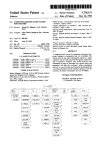
Initially, to understand the operation of this project, I interpret a case study
conducted by Charles E Hardy regarding infrared photo detector for measuring projectile
velocity that helps me on my research. He divide his project into two main parts which
are measurement and calculation apparatus for measuring the time or a ballistic
projectile enters and exits a prescribed course, basically a pair or screens which are
spaced apart at a known distance. The course will cause a perturbation or fluctuation in
the light intensity level received by one or more photo-optics sensor. This detection is
used to calculate the velocity of the ballistic projectile and thus display the calculation to
the screens. [6]
As for my project, the process is quite similar to the one’s describe above but
application of the process will be on straight path of highway road. Generally, my
7
project will be divided into three main stages which are the detection section, timing
system and calculation system. This block diagram will conclude my project concisely.
Block Diagram of
Figure 2.1:
the Project
From the figure above, a pair of
infrared detector in the red box will be the
detection system and the other
two stages will be timing
system and calculation section.
In this chapter, we will go into
detail on these three stages.
2.2
Detection System
Infrared system consists of a pair of infrared sources, photo detectors, and power
supply. There are many types of infrared radiation sources, depending on wavelength of
the infrared. For example, thermal radiation, cold radiation, and stimulated emission
infrared radiation. This table will conclude type of infrared radiation with its
corresponding range of wavelength and suitable field of application.
8
Table 2.1: Types of Infrared Radiation Sources [3]
Another type of infrared sources is LED Infrared. LED are PN junction devices
that give off light radiation when biased in a forward direction. Ideally, the optical
source has to be able to transmit at a minimum distance of highway road width. In
Malaysia, standard width of highway road is 3.65m [7]. In order to control maximum
distance of the transmitted infrared, several factors have to be considered, which are
irradiance of the receiver, Ee intensity of the emitter, Ie, NEP and detectivity, D*. A
quadratic relationship between the transmission distance and irradiance of the receiver
has to be assumed. From the assumption, the maximum distance is calculated as [8]:
9
(2.1)
For my project, since I am only implemented a model of speed trap system, I use
LED infrared as the beam source. There are a few advantages of using infrared as the
optical sources. The infrared light is not visible to human naked eye. It makes infrared
LED perfect enough for sensor application. Compared to laser diode, it is not safe and
not convenience to use in short distance sensor application. As for the photo detector, I
chose infrared receiver. The reason is because the product was cheap and easy to buy at
many electronic component stores. Both infrared LED and photo detector is shown in
figures below.
Figure 2.2: Infrared LED
10
Figure 2.3: infrared Receiver
The transmission range of the optical sources depends on its intensity. Let us
look at the curves of radiant intensity vs Transmission range. In this case, we use
TSOP4838 IR receiver.
Figure 2.4: Maximum Transmission Range with TSOP4838 as a Function of the
Radiant Intensity of the Emitter [8]
Although we have made the assumption that relationship between irradiance and
transmission distance does follow a quadratic curve, but in practical, usually this
assumption is not fully accurate [8]. However, from the curves, we still could see that
with an increasing value of radiant intensity of the emitter, Ee, the transmission distance
is also increased.
11
For power supply, since this is just initial modeling of the system, I use 9V
battery for this detector part together with 12V voltage regulator.
2.3
Timing System
After the photo detector receives infrared light, it will send an output signal to
timing system. This signal will trigger the timer to start measuring time of the crossing
car but before that, the signal need to be converted to digital signal first. There are a
number of ways to implement timing system for this purpose. The idea is to use time
taken for the car to travel a fixed distance into velocity equation. Signal from the other
photo detector will trigger the timer and stop the measurement through appropriate
define port. One way is by using LM358 timer chip [10]. This method basically
implemented another circuit to be installed with sensor. Another efficient way is to use
simple software develop using programming language and load it into PIC. This is what
I done. This method is costly effective and easy to troubleshoot. Another advantage of
using this technique is power supply could be reduced into one power supply for many
function of the system. The timer was then viewed using LCD 16x2.
2.4
Calculation Section
For my project, the calculation part was also done using PIC microcontroller. By
controlling the delay, velocity of the car was viewed on LCD 16x2.
2.5
Previous Vehicle Speed Detection [11,12]
As stated above, there are various types of speed trap system implemented to
capture guilty driver among the world. This involves classic self tracing method like
pacing method and VASCAR method until new technology radar system.
12
2.5.1
Pacing Method
Pacing method is an old classic method used to estimate velocity of the car. It is
done by assigning a police to follow guilty driver by self driving behind the target car.
Then, the police officer will estimate speed of target car by looking at speedometer in
his car. This method is usually done in night. For easy understanding of the method,
consider figure below. It shows how the pacing method works and how to estimate the
target car velocity.
Officer Speed, V1
Officer
Target
Initial distance, d1
Where you are
before
Target Car Speed, V2
Officer
Target
Officer Speed, V1
Road
Distance
target car
travel, d2
Figure 2.5: Pacing technique
Formula of pacing technique:
13
(2.2)
=
From above equation, it is concluded that the faster the police car bearing the
target, the more distance he will cover over any interval. This method seems to have
major disadvantages on accuracy issues. From the formula, we indicate that the farther
back the officer, the less accurate the pace. Ideally, to make the pace accurate, the police
officer has to maintain distance between patrol car and target car as long as time target
car is being paced.
2.5.2
VASCAR Method
VASCAR is an acronym for Visual Average Speed Computer and Recorder.
Basically, VASCAR system includes stopwatch and measuring device. In speed trap
application, police officer use VASCAR to measure a section of road. When target car
enter the corresponding VASCAR covered section, the officer will start the VASCAR
switch and stop the switch when the target car leave the section. VASCAR system
shows velocity of target car over section of the road.
Despite the systematic approach on VASCAR section, main deficiency of this
system is it’s depend on the officer who push the switch. In fact, the farther the officer
from VASCAR section point, the more probability to occur error since officer’s
observation from far place is limited.
2.5.3
Aircraft Method
14
This method is a further improvement of VASCAR method whereas a helicopter
is used to push VASCAR switch and speed of the car is determined in the helicopter
above the air. When the vehicle passes through the VASCAR section, a radio is used to
inform another officer waiting on the side of road. To make the above observer easy to
indicate VASCAR section, a mark is placed on the road. The system diagram is shown
in figure below.
Helicopter
(aircraft)
Mark Sign
Target Car
Figure 2.6 : Aircraft method
Despite the further improvement, there are still critical deficiencies in this system.
Again, if the officer in the aircraft didn’t push the VASCAR button correctly in timing,
the estimated velocity is not accurate. Plus, this method is not cost effective, so it’s not a
good choice to be implemented in the whole country.
2.5.4
Hoses Method
15
The operation of this system easily understands by look at the figure below.
Figure 2.7 : Hoses Method
A rubber hose is placed across the road as the switch to the system. When a car
hit the hose, box that contain stopwatch will start measure time until the car hit the other
side of the hose. This data was then sent to receiver wirelessly. The speed of vehicle was
estimated in the receiver on the police car.
2.5.5
Orbis Method
Orbis come from Greek words which means “eye”. Orbis traffic speed detection
systems consist of a capture camera, and rollover sensor in the traffic lane. When a
guilty driver which travel faster than preset speed of Orbis, the sensor will trigger
16
capture camera installed with Orbis to take picture of the car. Details like date, time, and
vehicle speed were included together with the picture.
Because of the system that clearly installed in side of the road, guilty driver
could easily detect the trap and avoid the system. This will be a major disadvantage of
the speed trap system, as we want to catch and reduce numbers of guilty driver
nowadays. The graphical picture of the system is as follow:
Capture Camera
Target Car
Figure 2.8 : Orbis method
2.5.6
Traffic Radar
Figure below shows briefly about radar system. Basically, radar works like beam
of light. They propagate in straight direction. When a vehicle cross the radar beam, it
will reflect the beam to the receiver, before further analysis was done. At receiver, they
estimate speed of the car by using Doppler Effect. The propagating wave was tuned to a
certain frequency at moving vehicle. When the vehicle reflects the wave to receiver, the
wave was shifted as outlined by relatively Doppler effects. This new frequency is then
used to estimate velocity of the vehicle.
17
Figure 2.9: Traffic radar.
However, since radar move in straight direction, it comes to problems when
radar is used on curves or hills road. This is known as antenna positioning error. Other
types of error that radar made are look past error, where radar detect higher size vehicle
when dealing with multiple vehicle in straight line, and vehicle interference error, where
the estimated speed obtained from detection was not accurate due to interference from
other vehicle nearby.
2.6
Conclusion
We have seen the previous version of speed trap system roughly. There are many
pros and cons for these systems. Next chapter will discuss in detail about speed trap
system using optical source and photo detector receiver, how the system could be an
alternative
for
previous
types
of
speed
trap
system.
18
CHAPTER 3
METHODOLOGY
3.1
Introduction
Before this, we have learnt the important concept of the project. In this chapter,
we will describe in theoretical how the steps taken to complete this project. This
description is based on discussion and research done where it is relevant in terms of time
taken to complete the project. Briefly, for this project, there are two main parts to be
implemented – hardware which is pair of infrared sensor and stopwatch and
programming part which is the instruction to the system. The sensor will generate a
voltage rise to trigger the stopwatch circuit and programming will instruct where and
when to trigger the circuit.
3.2
Work Flow for the Whole Project
To summarize overall flow of my project, study the flow chart below:
19
Start
Planning
Write program for PIC
microcontroller
Implement hardware
Test
Modify/Trobleshoot
programming and
hardware
Ok
End
Figure 3.1: Project Outline Flow Chart
20
3.3
Related Theoretical and Technology
To begin with, before the project was done, I have studied related concept
involve in this project, generally the operation of sensor and microcontroller chip. For
my project, main resource to study the concept and related theory will be from jurnal,
books and course conducted by professional lecturers in UTM. I went through internet
and search information relating photonic sensor. However, the scope of photonic sensor
is very large. From there I generally identified what is photonic sensor and could be able
to do further research. For example, I could identified, what type of source that I want to
use, what is the range of source wavelength, what kind of detector to be used an etcetra.
I also went through the relevant thesis done by previous graduates in UTM and get some
concepts and knowledge to start up my project. From the information I have got, I could
design block diagram, related circuit that is being used in my project, and could list
down what is the component to be used in the whole project.
Most important theoretical of this project are optical communication. Basic
optical system uses light as the primary medium to carry information through a medium
to the receiver. This three main things to be considered are optical sources, whether LED
or laser diode, propagating medium, which is a platform for light rays to propagate and
lastly the photo detector, basically, a device to receive light rays and change it to
electrical signal. For my project, the optical sources is infrared LED, air as the medium
and infrared receiver as the photo detector.
3.3.1
The Infrared
Infrared lies between visible light and microwave portion in electromagnetic
spectrum.
21
Figure 3.2 : Infrared Range in Electromagnetic Spectrum
From above figure, infrared was divided into four region which are near infrared,
middle infrared, far infrared and extreme infrared region. From Hamamitsu datasheet
[hamamitsu], it is shown that, the variety of infrared region was useful for many types of
applications. The spectral region and nomenclature are actually vary according to the
author but these terminology suggested here were following standard teminology
suggested by Ballard [14]. Except for extreme infrared region, the first three
subdivisions includes region in which the earth’s atmosphere is relatively transparent
and in XIR, the atmosphere is essentially opaque for paths more than a few meters long
[13].
The operation of infrared LED is the same with other light emitting things.
Basically, this semiconductor have an active region of minority carrier in opposite type
region. Normally empty electron states in conduction band of p type material and
normally empty hole states in the valence band of n type material are populated by
injected carriers which recombine across the bandgap. This recombine process make
these carriers to change their energy state and spontaneously emit photons. [15]
22
As for this project, operating wavelength (λs) of the infrared LED that I’ve used
was 0.94µm which is in near infrared region. This is an important charateristic for
optical communication, since λs has to be synchronize with spectral range of photo
detector. Another important thing to consider is efficiency of infrared LED. Efficiency
of optical sources is ratio of number of output photons to number of injected electrons.
This means, LED thata emits more photons good optical source for photo detector to
detect the light ray.
3.3.2
The Photo Detector
In order for optical communication system to complete, it has to have a detector
to convert the optical input into electrical signal before further analysis is done.
Performance of an optical communication system is determined here at photodetector.
The operation of photo detector is slightly different to optical source. A photo
detector is similar in structure to the p-n junction diode, but the junctions can be exposed
to external light, that forming a third optical “terminal”. The diode is reverse biased and
the electric dield developed across the p-n junction sweeps mobile carriers (holes and
electron) to their respective majority sides to create a depletion region. This barrier stop
majority carriers crossing the junction in the opposite direction to the field. The field
accelerates minority carriers from both sides to the opposite side of the junction, forming
the reverse leakage current of the diode. [15]
Important properties of a photo detector is that, it will detect only wavelength
less than its cutoff wavelength, λc. Efficiency of photo detector was determined by ratio
of number of electrons collected to number of incident photon absorbed.
23
3.4
Designing Detection System
This is the critical part of the project. The detection will detect a speeding car
using pair of infrared emitter and photo detector. The needs of this system to deduce
what are happening or when to start working is the fundamental of sensor application. It
is important to have a good detection system because in order to detect high speed car,
we have to make sure the transmitted infrared is good enough in terms of its attenuation
and scattering process when it propagate through air. Plus, received power from source
has to be sufficient to trigger the timing system to start measure time taken for the car to
cross two detectors in fixed distance before this time measurement is used to calculate
speed of the car.
The significant component of detection system was voltage comparator. A
comparator is electronic components that compares voltage or current and use the larger
voltage or currents as the output. For my project, I have used LM324N voltage
comparator which has four output pins to be used. However, because of the sensor need
to be separated apart, I only used one output pin per sensor. The corresponding pin
diagram for LM324N is shown in the figure below:
Figure 3.3: Corresponding pin diagram for LM324N
24
Pin 1, 7, 8 and 14 are the output pins. In designing motion sensor, I was using
one of the comparator in this chip and comparing voltage across photo detector and
voltage from sensor source as the input 1+ and input 1- of the comparator. For easy
understanding of operation of detector, consider figure 3.3 and 3.4 below.
Infrared
Emitter
Infrared
Emitter
Fixed distance
3.65 m
Speeding Car
Photo Detector
Photo Detector
Figure 3.4 : Detection System
From figure above, the value 3.65m is typical value for width of highway road
in Malaysia []. When IR light falling on the photo detector is blocked, (i.e. car cross the
first sensor), its conductance will decrease and voltage across photo detector will rise.
When voltage across photo detector is large enough compared to sensor source voltage,
the output of voltage comparator will turn ON and lit the LED. Take note at the
connection of input 1+ and input 1- of comparator. Because we want the output voltage
to trigger the timer when car cross infrared light, we have to connect it in a way that is
shown in the circuit diagram below:
25
Figure 3.5: The Detector Circuit
The diagram shows that photo detector voltage was connected at input 1- pin and
sensor source voltage was connected to input 1+ pin. This means, when car cross the
sensor, the photo detector was dark i.e. infrared light did not received by photo detector.
So, as explained before, this will raise the photo detector voltage and thus lit the LED.
3.5
Timing System Development
26
There is many ways to implement timing system as explained before in chapter 2.
Since I was using PIC microcontroller chip as the main component of the system, it is
important to understand the basic operation of microcontroller. Microcontroller is a chip
that is designed for embedded application. It stored program in ROM (Read Only
Memory) and usually, the program does not change.
3.5.1
The Microcontroller
A microcontroller has several advantages such as low cost and small size. These
advantages make it a very popular component in many applications. Below is the
Microchip PIC16F877A single PDIP chip.
Figure 3.6: Microchip PIC16F877A single PDIP chip.
27
Figure 3.7: PIC16F877A
PIC16F877 is one of the most commonly used microcontrollers in wide range of
application involves automotive, industrial, appliances and consumer applications.
Figure above shows corresponding pin diagram for this chip. Basically, there are 40 pins
which most of it are I/O ports for specific purpose, either general purpose I/O or reserve
PIC function. The core features of PIC16F877 are: [16]
•
High performance RISC CPU
•
Only 35 single word instructions to learn
•
All single cycle instruction except for program branches which
are two cycle
•
Operating Speed: DC – 20 MHz clock input DC – 200 ns
instruction cycle
•
Up to 8K x 14 words of FLASH Program Memory.
Up to 368 x 8 bytes of Data Memory (RAM)
Up to 256 x 8 bytes of EEPROM Data Memory
•
Pin out compatible to the PIC16C73B/74B/76/77
•
Interrupt capability (up to 14 sources)’
•
Eight level deep hardware stack
•
Direct, indirect and relative addressing modes
•
Power-on Reset (POR)
•
Power-up Timer (PWRT) and Oscillator Start-Up Timer
(OST)
28
•
Watchdog Timer (WDT) with its own on-chip RC oscillator
for reliable operation
•
Programmable code protection
•
Power saving SLEEP mode
•
Selectable oscillator options
•
Low power, high speed CMOS FLASH/EEPROM technology
•
Fully static design
•
In-Circuit Serial Programming (ICSP) via two pins
•
Single 5V In-Circuit Serial Programming capability
•
In-Circuit Debugging via two pins
•
Processor rad/write access to program memory
•
Wide operatin voltage range: 2.0V to 5.5V
•
High Sink/Source Current: 25mA
•
Commercial, Industrial and Extended temperature ranges
•
Low power consumption:
-
< 0.6 mA typical @ 3V, 4 MHz
-
20 µA typical @ 3V, 32 kHz
-
< 1 µA typical standby current
For my project, this chip is very important because it could control things
based on instruction set by user via programming language. To communicate
between programming function and microchip, a programmer has to be used so that
29
what we instruct PIC to do, we could load it into the chip. There are many types of
programmer in the market depend on number of pins PIC have.
3.5.2
The SK40-C and UIC00A
SK40C is another enhanced version of 40 pins PIC microcontroller start up kit.
It is designed to offer an easy to start board for PIC microcontroller user. However, all
interface and program should be developed by user. This board comes with basic
element for user to begin project development. It offer plug and use features. This kit is
designed to offer: [17]
Industrial grade PCB · Every board is being fully tested before
shipped to customer
Compact, powerful, flexible and robust start-up platform
Suitable for hobbyists and experts
Save development and soldering time
No extra components required for the PIC to function
All 33 I/O pins are nicely labeled to avoid miss-connection by
users
Connector for UIC00A (low cost USB ICSP PIC Programmer) simple and fast
•
method to load program
Fully compatible with SK40B
No more frustrated work plugging PIC out and back for reprogramming
Perfectly fit for 40 pins 16F and PIC18F PIC
With UIC00A, program can be loaded in less than 5 seconds
More convenient to use and it is smaller than SK40B.
30
Maximum current is 1A.
Dimension: 85mm x 55mm
•
SK40C come with additional features:
2 x Programmable switch
2 x LED indicator
Turn pin for crystal. User may use others crystal provided.
LCD display (optional)
UART communication
USB on board.
And all the necessities to eliminate users difficulty in using PIC
Figure 3.8: SK40-C KIT
This kit was easy to use since it includes basic thing for a newbie PIC
programmer. For example, it offers LED and programmable switch, which usually used
as an early tutorial for PIC workshops. As explains before, users are able to utilize the
function of PIC by directly plugging in the I/O components in whatever way that is
31
convenient to user. With UIC00A connector on board, user can start developing projects
and have fun with this kit right away since the programmer to load program into PIC is
build in with this kit.
From the figure, we could see that part of the port in PIC has been set for
specific purpose. For example, ports RB0 and RB1 were set to push button while port
RB6 and RB7 were set to LED.
UIC00A is the programmer to be used in this project, since it is a low cost
programmer and fit with SK40-C kit hardware.
Figure 3.9: UIC00A Programmer
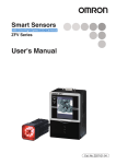
3.5.3
LCD Monitor (16x2 dot matrix)
For instant, we always want a speed trap system to be efficient enough in terms
of its function. Thus, for my project, instead of prepare the mechanism for detecting the
32
guilty driver, I also provide the function to display the velocity of the car that crossed the
sensor. This was important function since, for further analysis, we could determined
whether this car exceeded speed limit allowed by regulation or not. Figure below shows
the LCD monitor and appropriate pin configuration of the LCD.
Figure 3.10: 16x2 LCD monitor
As mentioned before, the SK40-C assigned its port to some function. For LCD
monitor, the appropriate port that has been set is port D. However, in writing program,
we have to tell PIC that we want to use the port in our program.
3.5.4
The software
Implementation of timing system involves hardware and software works. Before
this, I have explained the component involves with this project. Now, I will continue on
software part which is like the PIC brain. Computer programming is the process of
writing, testing, debugging, troubleshooting, and maintaining the source code of certain
computer programs. The source code is written in a programming language either in
high level language or in assembly language. The purpose of programming is to create a
program that act as instruction to PIC to do something. However, writing a program is
not just a simple instruction, we have to use the command prompt of the language to
translate our instruction into language that was understood by software.
A lot of available software that can be used to write the program such as Visual
Basic, Visual Studio, Micro C, Matlab, Lab View, MPLAB IDE, Bascom AVR and etc.
The selection of the software programming must be suit the microcontroller use. For
example, Bascom AVR only suitable for the Atmel microcontroller and not suitable for
33
the PIC microcontroller [tuah]. In this project, MPLAB software adapted with Hitech
PICC plugin compiler was used. The reason for choosing this software is simply because
it is easy to be used. Adapted with Hi-tech PICC compiler will make MPLAB applicable
to understand the C language.
The written program in the MPLAB IDE then will be compiled to produce .hex
file format. This .hex file format is a program file that will be used as the timing system
for my project. Corresponding instruction that was set could be seen from this flow
chart.
START
Print: “Welcome, IR PD
Speed Trap
NO
Start the
system?
Print: “READY!!”
NO
YES
Car cross
1st sensor?
END
YES
Start Stopwatch
Calculate Speed
and Display to LCD
NO
34
Figure 3.11: Flowchart Of Programming
First, when power supply was provided, the LCD displayed “…Welcome…”
and after a certain delay, it displayed “IR PD Speed Trap System”. Note that the use of
abbreviation was needed since maximum characters that could be displayed by LCD
monitor were 16.
Next, the system waits for user to push button so that the system was ready to be
used. After that, when the button was pushed, system will display “Ready!!!” at the
screen and at the same time, both sensors was ready to capture a car coming towards it.
When a car crossed the first sensor, LCD display will start counting time and
stopwatch was displayed at the LCD screen. When the car crossed the second sensor,
LCD display will stop the time and display the measured time for a while before display
the car’s velocity.
To start another measurement, push the reset button and system will start from
the beginning again. Note that my speed trap system use push button in its operation.
Because of my project was only a model of the system, I have program it to use push
button so that easy explanation could be made.
3.5.4.1 MPLAB Integrated Development Environment (IDE)
35
MPLAB IDE is a free, integrated toolset for the development of embedded
applications employing Microchip’s PIC microcontrollers. MPLAB IDE runs as a 32-bit
application on MS Windows, easy to use and includes a host of free software
components for fast application development and super-charged debugging. MPLAB
IDE also serves as a single, unified graphical user interface for additional Microchip and
third party software and hardware development tools. Moving between tools is a snap,
and upgrading from the free software simulator to hardware debug and programming
tools is done in a flash because MPLAB IDE has the same user interface for all tools
[18].
Figure 3.12: MPLAB Integrated Development Environment (IDE) Interface
3.5.4.2 PICkitTM 2
36
The PICkitTM 2 Development Programmer/Debugger is a low-cost development
tool with an easy to use interface for programming and debugging Microchip’s Flash
families of microcontrollers. The full featured Windows programming interface supports
baseline (PIC10F, PIC 12F5xx, PIC16F5xx), midrange (PIC12F6xx, PIC16F), PIC18F,
PIC24, dsPIC30, dsPIC33, and PIC32 families of 8-bit, 16-bit, and 32-bit
microcontrollers, and many Microchip Serial EEPROM products. With Microchip’s
powerful MPLAB IDE the PICkitTM 2 enables in-circuit debugging on most PIC
microcontrollers. In-Circuit-Debugging runs, halts, and single steps the program while
the PIC microcontroller is embedded in the application. When halted at a breakpoint, the
file registers can be examined and modified. [19]
Basically, this software was used to load the hex file into PIC by using UIC00A
programmer with rainbow cable connected to SK40-C kit. Apart from that, it also can be
used to clear the memory in PIC chip, in case of troubleshooting, clearing, or load
different types of program into the PIC.
The graphical interface of the PICkitTM 2 software is shown in the figure below.
Note that the PICkitTM 2 will display a message to indicate that the device is connected
and
ready
the hex file.
to
load
37
Figure 3.13: PICkitTM 2 Development Programmer/Debugger
3.6
Calculation System
Another part of the project is the calculation mechanism. The calculation is
basically based on speed equation which takes into consideration distance travel and
time taken to travel the distance. For my project, the calculation part was done by
program the PIC, since the memory allocated in PIC still sufficient to support this simple
calculation.
38
CHAPTER 4
RESULTS AND ANALYSIS
4.1
Introduction
Previous chapter described in depth methodology and models used to perform
the speed trap system. We now begin with this chapter by present the complete model of
speed trap system. As explained in the previous chapter, there are three main parts of the
39
circuit, which are a pair infrared sensor, SK-40C with PIC16F877A, which includes
another two parts that are timing system and calculation mechanism.
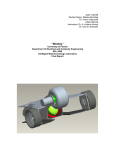
Below is the overview of complete models of the speed trap system that are
discussing above:
Figure 4.1: The Speed Trap Model
We could see that, there are three sources for two sensors and SK40-C kit. The
9V batteries were connected to 12V voltage regulator.
40
4.2
The Sensor Test
Figure below shows the complete sensor and how practically the sensor works.
Since the system implemented was only a model, I use small metal container to indicate
there is a car crossing the sensor. The hypothesis obtained is when a car (metal
container) does not cross the sensor, LED is not lit but when the car (metal container)
cross the sensor, the LED was lit.
Figure 4.2: Before metal container is placed – LED not lit
41
Figure 4.3: After metal container was placed – LED lit
Results obtained shows that the sensor works perfectly in detecting metal
container.
4.3
The Stopwatch and Calculation Test
In my project of speed trap system, stopwatch is the timing system used to
measure time taken for a car to travel a fixed distance. Figure below shows the results
obtained for this project:
42
Figure 4.4: The car cross first sensor, stopwatch start
Figure 4.5: The car cross second sensor, stopwatch stop
Figure 4.6: After a short delay, LCD display speed of the car
43
Result shows that the stopwatch and calculation was perfectly working. This
could be proved by manually calculating speed using time measured and speed equation
which is discuss below.
4.4
Analysis of the Result
From the obtained result, there are several points to be analyzed so that the
operation of the project could be understood. This section will discuss important analysis
related to result obtained.
4.4.1
The Oscillator
The heartbeat of every microcontroller design is the oscillator circuit. There are
two types of oscillator used in microcontroller which is resonant oscillator and crystal
oscillator. Most designs that demand precise timing over a wide temperature range use a
crystal oscillator. A crystal is a small wafer of high grade quartz cut at certain angle and
to a certain size. Thinner cuts will generate higher frequency crystal. Crystals are
designed and manufactured to operate at the rated frequency with a certain load
capacitance (CL). Metal leads are plated to the crystal for electrical connections. As a
voltage potential is placed across the crystal element, the force of trapped electrons in
the crystalline structure tends to deform the element. This is referred to as the
44
piezoelectric effect. As the element flexes, electrical impedance changes. [20] The
crystal acts as an electro-mechanical device and can be modeled as a network of passive
electrical components with a very sharp cut off frequency. The physical properties of
quartz make it very stable over both time and temperature.
Due to certain limitation of the crystal frequency stability to be generated, the
system could not calculate the speed of a very fast car. For SK40-C kit, the crystal used
within PIC is 20 MHz [17]. When a very fast car crossed this speed trap system, it
shows 0m/s speed which is not accurate.
4.4.2
The Calculation Process
For the calculation, the value displayed on LCD monitor is the result coming
from rounding process. As for the stopwatch, I have programmed it to measure up to
1/100 seconds time. However, when it comes to calculation section, I have round it so
that it will calculate the real number of time taken. For example, from figure 4.5, the
corresponding time taken for that particular case is 15.71 seconds, but speed displayed in
figure 4.6 was due to time equal to 15 seconds. So, 1/15 will approximately equal to
0.06 m/s.
45
CHAPTER 5
CONCLUSION
46
5.1
Introduction
The infrared photo detector speed trap system could provide possible alternative
to the police team and Malaysian Public Works Department (PWD). The easiness of its
application in many types of roads give a positive credit to the system compared to radar
based method that is used nowadays. However, there are still some technical hurdles to
be taken into further research and development of the system. For this chapter, I will list
down some recommendation some for future development so that this system could be
implemented efficiently in Malaysia.
5.2
Conclusion
The objectives of this project have been successfully achieved. The development
of infrared sensor to detect moving car was successful. The timing system to measure
time taken of the car to travel a fixed distance was working well according to its
operation and limit. Plus, the calculation of the car speed was perfectly works. This
project has completed in time and successful as the alternative for previous version of
speed trap system. As for my project, I have won the first runner up award for
telecommunication exhibition under category optical and photonics.
47
5.3
Future Recommendation
The system is design to calculate velocity of a car in highway. However, in real
practical, most of the cases involved too many cars and vehicle. In the near future, the
system could be upgraded to calculate multiple car or different types of vehicles and
much more practical cases so that the system could practically be implemented in the
country. This could be done using some memory chips and conditional circuit or
programming. Another recommendation is that the system works well up to display
speed of the car. It will be more efficient if the system could send a message to police
department with proper information such as estimated location, time, date and colour of
the car. This could be done by implementing another system involve GSM application as
the input to PIC microcontroller. In this system, also add another sensor that will detect
colour so that the overall system could send precise information to police department.
48
REFERENCE
1. Kaine-Krolak, M., & Novak, M. (1995). “An Introduction to Infrared Technology:
Apllication in the Home, Classroom, Worplace, and Beyond…”. Retrieved 31,
October 2010, from http://trace.wisc.edu/docs/ir_intro/ir_intro.htm.
2. The Timpra. (2010), How Speed Trap Radar Works, 30 October 2010,
http://www.timpra.com/new_timpra/how_Speed_Trap_Radar_works.htm
3. Komoto. “Material Science (Japanese), 14 (1977), Page 267”
4. Hamamutsu Photonics K.K, “Characteristics and Use of Infrared Detectors, Page 3”.
5. Brenda Williams, (2009),”Speed Traps”, Retrieved 1 November 2010, from
http://www.articlesbase.com/automotive-articles/speed-traps-1283860.html.
6. Charles E. Hardy, (2000), “Infrared Photodetector Apparatus For Measuring
Projectile Velocity, United States Patent, Page 3”.
7. (2009), “Maklumat Rasmi Lembaga Lebuhraya Malaysia (LLM)“ Retrieved 3,
November 2010, http://www.llmnet.gov.my/serverpages/resources/faq_list.aspx.
8. (2008), “General Overview of IR Transmission in Free Ambient”, Vishay
Semiconductor, Document number 80073, www.vishay.com.
9. (2001), “Photo Modules for PCM Remote Control Systems”, Vishay Telefunken,
Document Number 82090, www.vishay.com.
49
10. Michael Hattermann, (2001), “Speed Trap Enforcement Vehicle”, Machine
Intelligent Lab, Electrical and Computer Engineering Department, University of
Florida.
11. Radio Shack, Division of Tandy Corporation, “Questions And Answers About
Vehicle Speed Detection”, Texas, Fort Worth, USA.
12. David Brown, Beat Your Ticket, How Was Your Speed Measured?, retrieved on 24
April 2011, from http://www.nolo.com/legal-encyclopedia/free-books/beat-ticketbook/chapter6-2.html
13. Siti Marwangi Maharum, (2010), “Photonics Alcohol Detectors System For Syari’ah
Comliance Food And Beverage” (Degree Thesis), Universiti Teknologi Malaysia,
Skudai Johor.
14. L.R. Koller (1965). Ultraviolet Radiation. 2nd ed. New York: Wiley. 5.
15. Sevia M Idrus (2011), Teaching Slide, Optical Communication System, Universiti
Teknologi Malaysia, Skudai Johor.
16. PIC16F87XA Data Sheet, Microchip Technology.
17. SK40-C User’s Manual V1.1, (2010), Cytron Technology.
18. MPLAB IDE General Notes, (2011), retrieved from www.microchip.com
19. PIC KIT 2 General Notes (2010), retrieved from www.microchip.com
20. Cathy Cox and Clay Merritt, (2004) “Microcontroller Oscillator Circuit Design”,
Freescale Semiconductor.
50
21.
APPENDIX A
C Coding – Infrared Photo Detector Speed Trap System
//Program For Infrared Photo Detector Speed Trap System
//Author : Mohamad Amir Imran Bin Mohd Hasli
//4-SET
//Fakulti Kejuruteraan Elektrik
//Universiti Teknologi Malaysia
#include <pic.h>
__CONFIG ( 0x3F32 );//configuration for the
#define
#define
#define
#define
#define
#define
#define
#define
#define
rs
e
lcd_data
button1
button2
led1
led2
sensor1
sensor2
RB4
RB5
PORTD
RB0
RB1
RB6
RB7
RC1
RC2
microcontroller
//RS pin of the LCD display
//E pin of the LCD display
//LCD 8-bit data PORT
//global Variables
char i,b;
unsigned char ms
unsigned char second
unsigned char min
unsigned int speed
=
=
=
=
0;
0;
0;
0,a=0;
// function prototype
void delay(unsigned long data);
void send_config(unsigned char data);
void send_char(unsigned char data);
void lcd_goto(unsigned char data);
void lcd_clr(void);
void send_string(const char *s);
void LCD_char_to_no(unsigned char x, unsigned char y, unsigned char
digit_no, unsigned char character);
void LCD_set_DDRAM(unsigned char address);
void LCD_print(const char character);
51
void LCD_printxy_string(unsigned char x, unsigned char y, const char
*buffer);
void LCD_print_string(const char *buffer);
// main function
void main()
{
//set I/O input output
TRISB = 0b00000011; //configure PORTB I/O direction
TRISD = 0b00000000; //configure PORTD I/O direction
TRISC = 0b00000110;
PORTB = 0b00000000;
//setup ADC
ADCON1 = 0b00000110; //set ADx pin digital I/O
//configure lcd
send_config(0b00000001);
send_config(0b00000010);
send_config(0b00000110);
send_config(0b00001100);
send_config(0b00111000);
//clear display at lcd
//lcd return to home
//entry mode-cursor increase 1
//display on, cursor off and cursor blink off
//function set
//display startup message
lcd_clr(); //clear lcd
lcd_goto(3); //set the lcd cursor to location 3
send_string("..Welcome.."); //display "..Welcome.."
delay(200000);
lcd_clr();
lcd_goto(0); //set the lcd cursor to location 3
send_string("IR PD Speed"); //display "IR PD Speed"
lcd_goto(16);
send_string("Trap System"); //display "Trap System"
delay(100000);
while(1)
{
unsigned long n;
while(1)
{
if(!button1)
{break;}
else;
}
delay(50000);
lcd_clr();
lcd_goto(5);
send_string("READY!");
while(1)
{
if(!sensor1)
{break;}
else;
52
}
lcd_clr();
ms=0;
second=0;
min=0;
lcd_goto(6);
send_string(":");
LCD_char_to_no(10,1,2,ms);
LCD_char_to_no(7,1,2,second);
lcd_goto(9);
send_string(":");
LCD_char_to_no(4,1,2,min);
while(sensor2)
{
n++;
if(n>=600)
{
ms++;
n=0;
LCD_char_to_no(10,1,2,ms);
}
else if(ms>=100)
{
if(led1==1)
{led1=0;}
else if(led1==0)
{led1=1;}
second++;
ms=0;
LCD_char_to_no(7,1,2,second);
}
else if(second>=60)
{
min++;
second=0;
LCD_char_to_no(4,1,2,min);
}
}
led1=led2=1;
delay(300000);
lcd_clr();
delay(50000);
speed = 100/second;
//change distane
lcd_goto(0);
send_string("Speed =");
LCD_char_to_no(8,1,3,speed);
lcd_goto(9);
send_string(".
m/s");
LCD_char_to_no(10,1,2,speed);
}
}
53
// functions
void delay(unsigned long data) //delay function, the delay time
{ for( ;data>0;data--);
//depend on the given value
}
void send_config(unsigned char data) //send lcd configuration
{
rs=0; //set lcd to configuration mode
lcd_data=data; //lcd data port = data
e=1; //pulse e to confirm the data
delay(50);
e=0;
delay(50);
}
void send_char(unsigned char data) //send lcd character
{
rs=1; //set lcd to display mode
lcd_data=data; //lcd data port = data
e=1; //pulse e to confirm the data
delay(10);
e=0;
delay(10);
}
void lcd_goto(unsigned char data) //set the location of the lcd cursor
{
if(data<16)
{
send_config(0x80+data);
}
else
{
data=data-20;
send_config(0xc0+data);
}
}
void lcd_clr(void) //clear the lcd
{
send_config(0x01);
delay(600);
}
void send_string(const char *s) //send a string to display in the lcd
{
while (s && *s)send_char (*s++);
}
void LCD_char_to_no(unsigned char x, unsigned char y, unsigned char
digit_no, unsigned char character)
{
unsigned char ten = 0, hundred = 0;
if(y == 1)
LCD_set_DDRAM(x);
else if(y == 0)
LCD_set_DDRAM(0x40+x);
while(character > 99){
character -= 100;
54
hundred++;
}
while(character > 9){
character -= 10;
ten++;
}
hundred += 0b00110000;
ten += 0b00110000;
character += 0b00110000;
//convert to string binary
if(digit_no > 2)
LCD_print(hundred);
if(digit_no > 1)
LCD_print(ten);
if(digit_no > 0)
LCD_print(character);
}
void LCD_print(const char character)
{
e=1;
lcd_data=character;
rs=1;
//write data register
e=1;
delay(10);
e=0;
delay(100);
}
void LCD_printxy_string(unsigned char x, unsigned char y, const char
*buffer)
//max string size is 16
{
if(y == 1)
//only string no repeating
send_config(x);
else if(y == 0)
send_config(0x40+x);
else if(y == 3)
send_config(0x10+x);
else if(y == 2)
send_config(0x50+x);
LCD_print_string(buffer);
}
void LCD_print_string(const char *buffer)//always repeat the string
until the pixels being full
{
while(*buffer)
LCD_print(*buffer++);
}
55
void LCD_set_DDRAM(unsigned char address)
//0x00 <= address <= 0x27 display data RAM(DDRAM) is set in the
address counter(AC)
{
address += 0b10000000;
//0x40 <= address <= 0x67
lcd_data=address;
rs=0;
e=1;
//write instruction register
delay(10);
e=0;
delay(100);
}
56
APPENDIX B
Telecommunication Exhibition Certificate First Runner Up Winner Award