1
MCHPFSUSB Firmware
User’s Guide
© 2007 Microchip Technology Inc.
DS51679A
Note the following details of the code protection feature on Microchip devices:
•
Microchip products meet the specification contained in their particular Microchip Data Sheet.
•
Microchip believes that its family of products is one of the most secure families of its kind on the market today, when used in the
intended manner and under normal conditions.
•
There are dishonest and possibly illegal methods used to breach the code protection feature. All of these methods, to our
knowledge, require using the Microchip products in a manner outside the operating specifications contained in Microchip’s Data
Sheets. Most likely, the person doing so is engaged in theft of intellectual property.
•
Microchip is willing to work with the customer who is concerned about the integrity of their code.
•
Neither Microchip nor any other semiconductor manufacturer can guarantee the security of their code. Code protection does not
mean that we are guaranteeing the product as “unbreakable.”
Code protection is constantly evolving. We at Microchip are committed to continuously improving the code protection features of our
products. Attempts to break Microchip’s code protection feature may be a violation of the Digital Millennium Copyright Act. If such acts
allow unauthorized access to your software or other copyrighted work, you may have a right to sue for relief under that Act.
Information contained in this publication regarding device
applications and the like is provided only for your convenience
and may be superseded by updates. It is your responsibility to
ensure that your application meets with your specifications.
MICROCHIP MAKES NO REPRESENTATIONS OR
WARRANTIES OF ANY KIND WHETHER EXPRESS OR
IMPLIED, WRITTEN OR ORAL, STATUTORY OR
OTHERWISE, RELATED TO THE INFORMATION,
INCLUDING BUT NOT LIMITED TO ITS CONDITION,
QUALITY, PERFORMANCE, MERCHANTABILITY OR
FITNESS FOR PURPOSE. Microchip disclaims all liability
arising from this information and its use. Use of Microchip
devices in life support and/or safety applications is entirely at
the buyer’s risk, and the buyer agrees to defend, indemnify and
hold harmless Microchip from any and all damages, claims,
suits, or expenses resulting from such use. No licenses are
conveyed, implicitly or otherwise, under any Microchip
intellectual property rights.
Trademarks
The Microchip name and logo, the Microchip logo, Accuron,
dsPIC, KEELOQ, KEELOQ logo, microID, MPLAB, PIC,
PICmicro, PICSTART, PRO MATE, rfPIC and SmartShunt are
registered trademarks of Microchip Technology Incorporated
in the U.S.A. and other countries.
AmpLab, FilterLab, Linear Active Thermistor, Migratable
Memory, MXDEV, MXLAB, SEEVAL, SmartSensor and The
Embedded Control Solutions Company are registered
trademarks of Microchip Technology Incorporated in the
U.S.A.
Analog-for-the-Digital Age, Application Maestro, CodeGuard,
dsPICDEM, dsPICDEM.net, dsPICworks, dsSPEAK, ECAN,
ECONOMONITOR, FanSense, FlexROM, fuzzyLAB,
In-Circuit Serial Programming, ICSP, ICEPIC, Mindi, MiWi,
MPASM, MPLAB Certified logo, MPLIB, MPLINK, PICkit,
PICDEM, PICDEM.net, PICLAB, PICtail, PowerCal,
PowerInfo, PowerMate, PowerTool, REAL ICE, rfLAB, Select
Mode, Smart Serial, SmartTel, Total Endurance, UNI/O,
WiperLock and ZENA are trademarks of Microchip
Technology Incorporated in the U.S.A. and other countries.
SQTP is a service mark of Microchip Technology Incorporated
in the U.S.A.
All other trademarks mentioned herein are property of their
respective companies.
© 2007, Microchip Technology Incorporated, Printed in the
U.S.A., All Rights Reserved.
Printed on recycled paper.
Microchip received ISO/TS-16949:2002 certification for its worldwide
headquarters, design and wafer fabrication facilities in Chandler and
Tempe, Arizona; Gresham, Oregon and design centers in California
and India. The Company’s quality system processes and procedures
are for its PIC® MCUs and dsPIC® DSCs, KEELOQ® code hopping
devices, Serial EEPROMs, microperipherals, nonvolatile memory and
analog products. In addition, Microchip’s quality system for the design
and manufacture of development systems is ISO 9001:2000 certified.
DS51679A-page ii
© 2007 Microchip Technology Inc.
MCHPFSUSB FIRMWARE
USER’S GUIDE
Table of Contents
Preface ........................................................................................................................... 1
Chapter 1. Using the Microchip USB Firmware Framework
1.1 Highlights ........................................................................................................ 5
1.2 Overview of the Framework ........................................................................... 5
1.3 USB Firmware in the Framework ................................................................. 12
Index ............................................................................................................................. 23
Worldwide Sales and Service .................................................................................... 24
© 2007 Microchip Technology Inc.
DS51679A-page iii
MCHPFSUSB Firmware User’s Guide
NOTES:
DS51679A-page iv
© 2007 Microchip Technology Inc.
MCHPFSUSB FIRMWARE
USER’S GUIDE
Preface
NOTICE TO CUSTOMERS
All documentation becomes dated, and this manual is no exception. Microchip tools
and documentation are constantly evolving to meet customer needs, so some actual
dialogs and/or tool descriptions may differ from those in this document. Please refer
to our web site (www.microchip.com) to obtain the latest documentation available.
Documents are identified with a “DS” number. This number is located on the bottom
of each page, in front of the page number. The numbering convention for the DS
number is “DSXXXXXA”, where “XXXXX” is the document number and “A” is the
revision level of the document.
For the most up-to-date information on development tools, see the MPLAB® IDE
on-line help. Select the Help menu, and then Topics to open a list of available on-line
help files.
INTRODUCTION
This document discusses the technical details and functionality of the MCHPFSUSB
Firmware. It assumes that the programmer already: a) Knows how to write C
programs; b) Knows how to use the MPLAB Integrated Development Environment
(IDE); c) Understands the microcontroller data sheet for which the code is being written;
d) Understands some basic USB concepts, such as those covered in chapters 5, 8
and 9 in the official USB 2.0 specifications. Items discussed in this chapter include:
•
•
•
•
•
•
About This Guide
Recommended Reading
The Microchip Web Site
Development Systems Customer Change Notification Service
Customer Support
Document Revision History
ABOUT THIS GUIDE
Document Layout
This document describes how to use the MCHPFSUSB Firmware for creating USB
applications. The manual layout is as follows:
• Chapter 1: Using the Microchip USB Firmware Framework provides an
overview of the framework, and how to use it in the design of new USB solutions.
© 2007 Microchip Technology Inc.
DS51679A-page 1
Preface
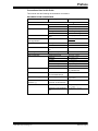
Conventions Used in this Guide
This manual uses the following documentation conventions:
DOCUMENTATION CONVENTIONS
Description
Arial font:
Italic characters
Initial caps
Quotes
Underlined, italic text with
right angle bracket
Bold characters
‘bnnnn
Text in angle brackets < >
Courier New font:
Plain Courier New
Italic Courier New
0xnnnn
Square brackets [ ]
Curly brackets and pipe
character: { | }
Ellipses...
© 2007 Microchip Technology Inc.
Represents
Examples
Referenced books
Emphasized text
A window
A dialog
A menu selection
A field name in a window or
dialog
A menu path
MPLAB® IDE User’s Guide
...is the only compiler...
the Output window
the Settings dialog
select Enable Programmer
“Save project before build”
A dialog button
A tab
A binary number where n is a
digit
A key on the keyboard
Click OK
Click the Power tab
‘b00100, ‘b10
File>Save
Press <Enter>, <F1>
Sample source code
Filenames
File paths
Keywords
Command-line options
Bit values
A variable argument
#define START
autoexec.bat
c:\mcc18\h
_asm, _endasm, static
-Opa+, -Opa0, 1
file.o, where file can be
any valid filename
A hexadecimal number where 0xFFFF, 0x007A
n is a hexadecimal digit
Optional arguments
mcc18 [options] file
[options]
Choice of mutually exclusive errorlevel {0|1}
arguments; an OR selection
Replaces repeated text
var_name [,
var_name...]
Represents code supplied by void main (void)
user
{ ...
}
DS51679A-page 2
MCHPFSUSB Firmware User’s Guide
RECOMMENDED READING
This user's guide describes how to use the MCHPFSUSB Firmware. Other useful
documents are listed below. The following documents are available and recommended
as supplemental reference resources.
MCHPFSUSB Firmware Release Notes
As new versions of the MCHPFSUSB Firmware are developed, they will be distributed
along with release notes that may cover specific and key items not necessarily covered
in this User’s Guide. When new versions are released, they will be posted at the
Microchip USB design center:
http://www.microchip.com/usb/ (click on the “Full-Speed USB Solutions” link)
PICDEM FS USB Demonstration Board User’s Guide (DS51526)
PIC18F87J50 FS USB Plug-In Module User’s Guide (DS51678)
Official USB 2.0 Specifications
Chapter 9 in the official USB 2.0 specifications covers the commands that all USB
peripheral devices must support. This chapter is especially important as it strongly
influences the requirements of USB firmware. Chapters 5 and 8 also provide useful
information regarding how data moves across the USB. The official USB specifications
can be downloaded from the USB Implementers Forum web site:
http://www.usb.org/
THE MICROCHIP WEB SITE
Microchip provides online support via our WWW site at www.microchip.com. This web
site is used as a means to make files and information easily available to customers.
Accessible by using your favorite Internet browser, the web site contains the following
information:
• Product Support – Data sheets and errata, application notes and sample
programs, design resources, user’s guides and hardware support documents,
latest software releases and archived software
• General Technical Support – Frequently Asked Questions (FAQ), technical
support requests, online discussion groups, Microchip consultant program
member listing
• Business of Microchip – Product selector and ordering guides, latest Microchip
press releases, listing of seminars and events, listings of Microchip sales offices,
distributors and factory representatives
DS51679A-page 3
© 2007 Microchip Technology Inc.
Preface
DEVELOPMENT SYSTEMS CUSTOMER CHANGE NOTIFICATION SERVICE
Microchip’s customer notification service helps keep customers current on Microchip
products. Subscribers will receive e-mail notification whenever there are changes,
updates, revisions or errata related to a specified product family or development tool of
interest.
To register, access the Microchip web site at www.microchip.com, click on Customer
Change Notification and follow the registration instructions.
The Development Systems product group categories are:
• Compilers – The latest information on Microchip C compilers and other language
tools. These include the MPLAB C17, MPLAB C18 and MPLAB C30 C compilers;
MPASM™ and MPLAB ASM30 assemblers; MPLINK™ and MPLAB LINK30
object linkers; and MPLIB™ and MPLAB LIB30 object librarians.
• Emulators – The latest information on Microchip in-circuit emulators.This
includes the MPLAB ICE 2000 and MPLAB ICE 4000.
• In-Circuit Debuggers – The latest information on the Microchip in-circuit
debugger, MPLAB ICD 2.
• MPLAB IDE – The latest information on Microchip MPLAB IDE, the Windows®
Integrated Development Environment for development systems tools. This list is
focused on the MPLAB IDE, MPLAB SIM and MPLAB SIM30 simulators, MPLAB
IDE Project Manager and general editing and debugging features.
• Programmers – The latest information on Microchip programmers. These include
the MPLAB PM3 and PRO MATE® II device programmers and the PICSTART®
Plus development programmer.
CUSTOMER SUPPORT
Users of Microchip products can receive assistance through several channels:
•
•
•
•
Distributor or Representative
Local Sales Office
Field Application Engineer (FAE)
Technical Support
Customers should contact their distributor, representative or field application engineer
(FAE) for support. Local sales offices are also available to help customers. A listing of
sales offices and locations is included in the back of this document.
Technical support is available through the web site at: http://support.microchip.com
DOCUMENT REVISION HISTORY
Revision A (July 2007)
• Initial Release of this Document.
© 2007 Microchip Technology Inc.
DS51679A-page 4
MCHPFSUSB FIRMWARE
USER’S GUIDE
Chapter 1. Using the Microchip USB Firmware Framework
1.1
HIGHLIGHTS
The items discussed in this chapter are:
• Overview of the Framework
- Configuring MPLAB® IDE for the Framework
- Selecting the Microcontroller Configuration
• USB Firmware in the Framework
1.2
OVERVIEW OF THE FRAMEWORK
The Microchip USB Firmware Framework is a library that can be used to create new
USB applications. It can be thought of as a reference design project, containing the
necessary firmware code for USB operation and providing a placeholder for the user’s
code. The whole code project is contained within one single root project directory, with
many subdirectories for source code organization.
The USB Framework is based on the latest versions (as this is written) of Microchip’s
development tools. To provide the best level of USB application support, you should
verify that you have at least these revisions of the following tools before starting:
• MPLAB IDE, v 7.61
• Microchip C18 C Compiler, v 3.12
This section describes the importance in setting up the project paths and how the
framework is organized.
1.2.1
The Framework Directory Structure
The file structure consists of a collection of subdirectories and specific files under a root
project directory. The root directory for a USB project may be located in any location
and have any valid directory name; however, the subdirectories’ structure should
always be maintained. Each of the example projects use this structure.
The following subdirectories and files should always be present:
Subdirectories:
• _output: Central location for output files
• autofiles: Contains USB global configuration file and descriptors
• system: Contains USB firmware
• user: Placeholder for the user’s firmware
Files:
• CleanUp.bat: Delete all output files in this folder and any subdirectories.
• io_cfg.h: Maps pin names to pin functions; this file should be modified to match
each target board. The default example is designed for the PICDEM FS USB
demonstration board.
• main.c: The file which contains main() for the application.
• MCHPUSB.mcp: MPLAB IDE Project file.
• MCHPUSB.mcw: MPLAB IDE Workspace file.
© 2007 Microchip Technology Inc.
DS51679A-page 5
Using the Microchip USB Firmware Framework
1.2.2
The Framework Logical Structure
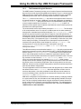
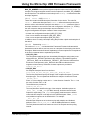
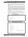
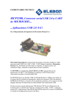
The USB Firmware Framework provides a set of modular firmware interfaces that handle most of the work for implementing USB communications. Figure 1-1 shows a typical
USB program flow. Each firmware reference project is written to have a cooperative
multitasking environment; thus, no blocking functions should be implemented.
The main() function is an infinite while loop that services different tasks. These can
be logically thought of as either a USB task or a user task. USB tasks are handled by
USBDriverService(), which polls and services all USB hardware interrupts. When
a control endpoint transaction is received, USBCtrlEPService() is called. All
transfers over the default control endpoints must follow the control transfer protocol as
described in the USB specification.
The control transfer service is provided by functions in usbctrltrf.c. The first stage
of all control transfers arrive as a request. A USB request can be either standard or
class-specific. A standard request is serviced by the USBCheckStdRequest(), which
handles the required requests as specified in Chapter 9 of the USB specification. A
class-specific request must be handled by the firmware file that knows how to service
it. Examples of device classes are Human Interface Device (HID) and Communication
Device Class (CDC). (The example in Figure 1-1 shows HID; it could refer to any other
device class just as easily.) The handlers for a class-specific request should be
contained in the specific device class firmware file, such as hid.c or cdc.c. The
naming scheme for a function that services a class-specific request is
USBCheck<class name>Request(), where <class name> can be any
class-specific names.
The USB enumeration process is handled mainly in usb9.c. One of the most important
steps in the enumeration process is the handling of a SET_CONFIGURATION request,
which is done by USBStdSetCfgHandler(). This function can be modified by the
user to call the appropriate functions to initialize the application endpoints. Each
specific device class firmware should have one endpoint initialization routine. The naming convention for this function is <class name>InitEP(), where <class name>
can be any device class names. An example is HIDInitEP(), which contains
example code on how to initialize a group of endpoints that are used in the class. Users
should take care to check which configuration index is being asked to be set by the
USB host. A device can have multiple configurations, and not all interfaces may be the
same across different configurations.
The user’s application code is also called from the main program loop; it resides under
the default function name, ProcessIO(). When the application needs to send or
receive a data packet, it can call a prewritten function that services the transmit or
receive functionality which is declared in the class-specific firmware code, such as
HIDRxReport()and HIDTxReport().
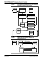
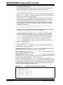
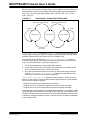
USB device configuration is also handled in a modular manner by modifying variables
in a small number of files; the information is then made globally available at compile
time. The files are tightly interdependent and pass information between themselves
during compile time to create the complete USB configuration. The relationships are
shown in Figure 1-2. Customizing the configuration files is discussed in Section 1.3
“USB Firmware in the Framework”.
© 2007 Microchip Technology Inc.
DS51679A-page 6
MCHPFSUSB Firmware User’s Guide
FIGURE 1-1:
RELATIONSHIPS BETWEEN MICROCHIP USB FRAMEWORK
FILES AND A TYPICAL HID APPLICATION
Program Memory
main.c
usbdrv.c
main.c
{
while(1)
}
USBDriverService()
usbdsc.c
usb9.c
usbctrltrf.c
USBCtrlEPService()
{
}
USBCheckStdRequest()
USBStdSetCfgHandler()
...
hid.c
USBCheckHIDRequest()
user.c
ProcessIO()
{
}
HIDInitEP()
TX and RX
Functions
usbcfg.h
Data Memory
USB
Configuration
usbmmap.c
USB RAM
Mapping
FIGURE 1-2:
COMPILE-TIME RELATIONSHIPS BETWEEN USB
CONFIGURATION FILES
User-Configurable Files
usbdcs.c
usbdsc.h
usbcfg.h
USB
Descriptor
Information
USB
Configuration
MAX_EP_NUMBER
Endpoint Buffer Descriptor Registers
Abstract
Endpoint
Definitions
Endpoint sizes
usbmmap.c
USB RAM
Mapping
Endpoint
Buffer
Variables
Class-Specific Firmware Files
hid.c (or cdc.c, etc.)
DS51679A-page 7
© 2007 Microchip Technology Inc.
Using the Microchip USB Firmware Framework
1.2.3
Configuring MPLAB IDE for the USB Framework
When setting up a project from the reference design, the first thing to check is the
project paths. These should be updated to reflect the actual project’s root directory as
needed. The steps in updating the project paths will be demonstrated through an
example.
In this example, we will use the HID Mouse Reference project, located in the directory,
C:\MCHPFSUSB\fw\HID\Mouse. You may need to adjust your target directories
according to where the project is actually located during installation.
To open a project workspace:
1. Launch MPLAB IDE.
2. From the MPLAB IDE menu bar, select File > Open Workspace...
3. Navigate and select the project or workspace file,
C:\MCHPFSUSB\fw\HID\Mouse\MCHPUSB.mcw (or MCHPUSB.mcp).
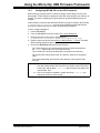
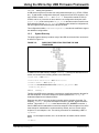
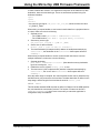
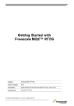
4. Return to the menu bar and select Project > Build Options... > Project. The Build
Options dialog appears (Figure 1-3).
5. Click on the Directories tab and verify the following:
- The “Output Directory” and “Intermediates Directory” paths should point to
the _output folder under your root project directory.
- The “Include Path” directory should point to the project’s root directory.
- The “Library Path” should point to the “lib” directory under the C18 program
folder.
- The “Linker-Script Path” should point to the directory of the project’s linker
script file.
Note 1:
2:
© 2007 Microchip Technology Inc.
In some cases, the C18 compiler may fail to compile correctly, giving an
error that certain header files from the mcc18 library could not be found.
In this case, add the path C:\mcc18\h after the project root path in the
“Include Path” field.
If the C18 compiler is installed in a path other than C:\mcc18\, the
actual path should be used instead.
DS51679A-page 8
MCHPFSUSB Firmware User’s Guide
FIGURE 1-3:
1.2.4
CONFIGURING MPLAB® IDE FOR THE MICROCHIP USB
FRAMEWORK
Selecting the Hardware Configuration
Microchip's current PIC18 USB microcontroller families share the same basic set of
USB registers and names. As a result, the MCHPFSUSB Framework can be ported to
work with the different PIC18 USB microcontroller families with little to no modification.
The MCHPFSUSB Framework is currently distributed as several separate projects
which all share the same basic USB “Chapter 9” firmware needed for device
enumeration. These individual projects differ in that they each include additional code
to demonstrate implementation examples for specific USB device classes. For
example, a Human Interface Device (HID) class USB device must support additional
commands specific to the HID class specifications, in addition to the Chapter 9
commands that all USB devices must support.
By default, these projects are configured to work with the PICDEM FS USB Demo
Board (microchipDIRECT part number: DM163025), which features the PIC18F4550
USB microcontroller.
DS51679A-page 9
© 2007 Microchip Technology Inc.
Using the Microchip USB Firmware Framework
To use these projects with other PIC18 USB microcontrollers or circuit board platforms,
the following changes will be needed:
1. Open the MPLAB IDE project.
2. Select the microcontroller which will be used:
Menu bar -->Configure -->Select Device.
3. Replace the linker script in the project with the appropriate device-specific linker
script. These can be found in the \lkr directory inside the default installation
directory for the C18 compiler.
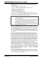
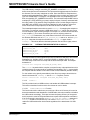
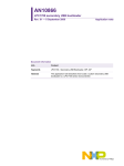
4. Edit the usbcfg.h file by uncommenting the #define statement for the demo
board which will be used (and comment the other choices). See highlighted section in Figure 1-4. This step may differ between the different projects, so refer to
the MCHPFSUSB release notes which are distributed with the firmware for more
details about this step.
Although the USB-specific registers are the same between the PIC18F4550 family and
other PIC18 USB microcontrollers, such as the PIC18F87J50 family, a few differences
still exist. For example, when configured for a PLL-based oscillator mode, the
PIC18F4550 will power-up by default with the PLL enabled. On the PIC18F87J50
family of devices, the PLL is initially disabled even when configured for a PLL-based
oscillator mode. User firmware must set the OSCTUNE<PLLEN> bit at least two milliseconds before enabling the USB module (if the USB module clock is being derived
from the PLL).
To accommodate these types of differences, the source code for the MCHPFSUSB
Framework uses #if defined(//demo board name) statements. By
uncommenting the #define statement of step 4, the C18 compiler will be able to know
which #if defined(//demo board name) statements are applicable for the demo
platform/device being used.
If developing for a non-Microchip demo board platform, additional changes may also
be needed. The example framework projects make use of the hardware features available on the demo boards, such as LEDs, push buttons, temperature sensor, RS-232
connector, etc. When developing for a different platform, these aspects of the projects
will either need to be replaced or removed. The io_cfg.h file maps functions to pin
names and will likely need modification.
© 2007 Microchip Technology Inc.
DS51679A-page 10
MCHPFSUSB Firmware User’s Guide
FIGURE 1-4:
DS51679A-page 11
SELECTING THE HARDWARE PLATFORM
© 2007 Microchip Technology Inc.
Using the Microchip USB Firmware Framework
1.3
USB FIRMWARE IN THE FRAMEWORK
The subdirectories’ autofiles and system contain the USB firmware source code in
the framework. Some of these files should never be modified, while others must be
edited to configure the application. Each folder and its files will be discussed in details
of what they do and how to modify them to match your application.
1.3.1
Autofiles Directory
This directory contains three key configuration files for USB operation:
• usbcfg.h: Global USB Configuration File
• usbdsc.c: USB Descriptor File
• usbdsc.h: USB Descriptor File Header
1.3.1.1
usbcfg.h
This header file is the most important file of the entire project. It defines the endpoints
mapping to their class functions. It also defines the Microchip USB ID (MUID) number,
which is used to determine which USB class currently owns the control transfer in
progress. Finally, it defines the maximum buffer size for endpoint 0.
To centralize the configuration of important USB features, all of the USB-related
compile-time options are found here. The file is constructed as a series of #define
compiler directives. The options to configure are:
•
•
•
•
•
•
•
•
EP0_BUFF_SIZE [buffer_size]
MAX_NUM_INT [max]
MODE_PP [_PPBMn]
UCFG_VAL [option1 | option2...]
USE_SELF_POWER_SENSE_IO
USE_USB_BUS_SENSE_IO
USB_USE_GEN or USB_USE_CDC or USB_USE_HID
MAX_EP_NUMBER [max_ep]
EP0_BUFF_SIZE defines the buffer size for endpoint 0. It can have a valid value of 8,
16, 32 or 64 bytes. This definition is used globally in the project for many things. It is
used during project build to allocate appropriate buffer size for endpoint 0. It is used in
the USB descriptor to notify the USB host of the size of the endpoint 0 buffer. It is also
used during control transfer operation.
When defining this variable, note that a low-speed USB device can only use an 8-byte
buffer, while a full-speed USB device can use an 8, 16, 32 or 64-byte buffer.
MAX_NUM_INT defines the size of the array which keeps track of the active alternate
setting for each interface, which can be switched during operation. Valid values are
integers [0, 1, 2,...]. If a device has multiple configurations, the number of interfaces
from the configuration with the highest number of interfaces should be used.
For example, a device with two configurations has three interfaces in the first
configuration and two interfaces in the second. In this case, MAX_NUM_INT should be
three.
MODE_PP defines the Ping-Pong Buffer mode to be used during run time. The function
of each mode is explained in the USB chapter of the device data sheet.
Note:
© 2007 Microchip Technology Inc.
The current version of the firmware only supports _PPBM0 mode.
DS51679A-page 12
MCHPFSUSB Firmware User’s Guide
UCFG_VAL defines the initial value for the UCFG Special Function Register. The
allowed values are:
•
•
•
•
•
_LS or _FS: Select Low or Full-Speed mode
_TRINT or _TREXT: Select Internal or External Transceiver mode
_PUEN: Use internal USB pull-up resistor
_OEMON: Use SIE output indicator
_UTEYE: Enable eye pattern test output
The options can be ORed together (for example, #define UCFG_VAL
_PUEN|_TRINT|_FS). This value is used by the firmware framework to initialize the
UCFG register. A full explanation of the options can be found in the description of the
UCFG register in the USB chapter of the device data sheet.
Note 1:
If the _LS option is selected, the device clock configuration must be
changed to support low-speed operation, Refer to the device data sheet
for additional information.
2:
The _UTEYE option is used only for device testing and never in live applications. When _UTEYE is enabled, the device transmits continuously. Do
not plug the device to a USB host when the option is enabled.
3:
Not all PIC18 USB microcontrollers support all of the listed settings. Refer
to the USB chapter in the device-specific data sheet to determine which
modes are valid for a given device.
USE_SELF_POWER_SENSE_IO indicates that the microcontroller is sensing the
presence of on-board power through an I/O pin. If the target board design does not use
an I/O pin to detect the presence of self-power, this definition must be commented out.
USE_USB_BUS_SENSE_IO indicates that the firmware will use the pin defined in
io_cfg.h to determine when to enable the USB module. If the target board design
does not use an I/O pin to detect the presence of the USB bus, this definition must be
commented out.
When USE_USB_BUS_SENSE_IO is undefined, the USB module will always be
enabled. Using this feature helps to improve the power efficiency of the system
because the USB module is only enabled when the bus is present. Additionally, in order
for the device to pass USB compliance certification, all self-powered devices are
required to support a bus sense feature. Self-powered devices which do not implement
this feature will fail the back drive voltage tests. The USB specifications require that
devices should not source current on D+ or D- (and never VBUS) unless the host is
actively powering the VBUS line. A self-powered device will not know when the host is
actively powering VBUS (and when it is acceptable to enable the D+ or D- pull-up
resistor) unless a bus sense feature is implemented. Purely bus-powered devices do
not need to implement this feature, and this feature may be commented out.
USB_USE_GEN, USB_USE_CDC and USB_USE_HID are used to indicate which
USB classes should be included in the code project. When each of these are defined,
it tells the USB global header file, usb.h, which class-specific header files to include.
The usb.h header is used globally as the necessary include file when using the USB
library. If the HID class is used, then hid.c and hid.h should also be added to the
MPLAB IDE project. If the CDC class is used, then cdc.c and cdc.h should also be
added to the MPLAB IDE project.
This definition is also used when the SET_CONFIGURATION request is received.
Users can modify the ‘Modifiable Section’ in the USBStdSetCfgHandler function in
usb9.c. The calls located in the modifiable section initialize endpoints used by each
specific USB class, which are mapped by usbcfg.h.
DS51679A-page 13
© 2007 Microchip Technology Inc.
Using the Microchip USB Firmware Framework
MAX_EP_NUMBER must equal the highest endpoint number used in the project. For
example, if the highest endpoint number used is endpoint 5, then MAX_EP_NUMBER
should equal five. This definition is used mainly in the usbmmap.c to allocate the buffer
descriptor registers.
1.3.1.2
usbdsc.c AND usbdsc.h
These files contain the USB descriptor information for the device. The main file,
usbdsc.c, defines the descriptor itself; usbdsc.h defines the descriptor structure,
which is used to calculate the descriptor size with the sizeof() statement. When a
descriptor is added or removed from the main configuration descriptor (i.e., CFG01),
the user must also change the descriptor structure defined in usbdsc.h.
A typical configuration descriptor consists of these components:
• At least one configuration descriptor (USB_CFG_DSC)
• One or more interface descriptors (USB_INTF_DSC)
• One or more endpoint descriptors (USB_EP_DSC)
In addition, there is usually a descriptor string that provides a plain text description of
the device.
1.3.1.2.1
Customizing usbdsc.c
The version of usbdsc.c included with the Framework Firmware indicates which
parameters must be defined, and can serve as a template for developing new device
descriptors. Most items should be self-explanatory, but some options are not explained
in the file’s comments and are expanded upon below.
• USB_CFG_DSC
The configuration attribute (the item immediately following the string index) must
always have the _DEFAULT definition at the minimum. Two additional options,
_SELF and _RWU, can be ORed with _DEFAULT. _SELF tells the USB host that
this device is self-powered, while _RWU tells the USB host that the device
supports remote wake-up. Definitions for these options are provided in
usbdefs_std_dsc.h.
• USB_EP_DSC
An endpoint descriptor has a form similar to:
sizeof(USB_EP_DSC),DSC_EP,_EP01_OUT,_BULK,64,0x00
The first two parameters specify the length of this endpoint descriptor (7) and the
descriptor type. The next parameter identifies the endpoint. It takes the format:
_EP<##>_<dir>
where ## is the endpoint number and dir is the direction of transfer. The dir has
the value of either ‘OUT’ or ‘IN’.
The definitions are provided in:
usbdefs_std_dsc.h.
The next parameter identifies the type of the endpoint. Available options are
_BULK, _INT, _ISO and _CTRL (for Bulk, Interrupt, Isochronous and Control
endpoints, respectively). The _CTRL is not typically used because the default
control transfer endpoint is not defined in the USB descriptors. When _ISO is
used, additional options can be ORed with it. For example:
_ISO |_AD |_FE
describes the endpoint as an isochronous pipe with adaptive and feedback
attributes. See usbdefs_std_dsc.h and the USB specification for details.
The final parameters define the maximum size of the endpoint and the polling
interval.
© 2007 Microchip Technology Inc.
DS51679A-page 14
MCHPFSUSB Firmware User’s Guide
• The USB Descriptor String
Rather than appearing as a simple string of text, the descriptor is formatted in a
particular data structure. The string descriptor array takes the format:
rom struct{byte bLength;byte bDscType;word string[size];}sdxxx={
sizeof(sdxxx),DSC_STR,<text>};
This structure provides a means for the C compiler to calculate the length of string
descriptor, sdxxx, where xxx is the string index number. The first two bytes of the
descriptor are the descriptor length and type.
The remaining <text> are string texts which must be in Unicode format. This is
achieved by declaring each character as a word type. The whole text string is
declared as a word array with the number of characters equal to <size>; which
must be calculated manually by counting characters and then entered into the
array declaration. For example, if the string is “USB”, then the string descriptor
should be (using index 02):
rom struct{byte bLength;byte bDscType;word string[3];}sd002={
sizeof(sd002),DSC_STR,'U','S','B'};
A USB project may have multiple strings. The firmware supports the management
of multiple strings through a look-up table, which is defined as:
rom const unsigned char *rom USB_SD_Ptr[]={&sd000,&sd001,&sd002};
The above example has 3 strings (sd000, sd001 and sd002). Strings can be
removed or added as needed. The strings are managed by the look-up table
USB_SD_Ptr; the index of the string must match the index position of the array,
(&sd000 must be in position USB_SD_Ptr[0], and so on). The look-up table
USB_SD_Ptr is used by the USBStdGetDscHandler function in usb9.c.
sd000 is a specialized string descriptor. It defines the language code, which is
usually US English (0x0409).
1.3.1.2.2
Customizing usbdcs.h
In the header file, usbdsc.h, variables for each of the descriptor components are
named with the following conventions:
USB_CFG_DSC types are named cdxx, where xx is the configuration number. This
number should match the actual index value of the configuration.
USB_INTF_DSC types are named i<yy>a<zz>, where yy is the interface number
and zz is the alternate interface number.
USB_EP_DSC types are named ep<##><d>_i<yy>a<zz>, where ## is the endpoint
number and d is the direction of transfer. The interface name should also be listed as
a suffix to identify which interface the endpoint belongs to.
Example 1-1 shows the structure in usbdsc.h of a configuration descriptor. This
device has one configuration with two interfaces: interface 0 with two endpoints (in and
out), and interface 1 with one endpoint (in). The hierarchy of the descriptors shown here
follows the USB specification requirement. All endpoints belonging to an interface
should be listed immediately after that interface.
EXAMPLE 1-1:
DEFINING A CONFIGURATION IN USBDSC.H
#define CFG01 rom struct
{ USB_CFG_DSC cd01;
USB_INTF_DSC i00a00;
USB_EP_DSC
ep01o_i00a00;
USB_EP_DSC
ep01i_i00a00;
USB_INTF_DSC i01a00;
USB_EP_DSC
ep02i_i01a00;
} cfg01
DS51679A-page 15
\
\
\
\
\
\
\
© 2007 Microchip Technology Inc.
Using the Microchip USB Firmware Framework
1.3.1.2.3
Adding Configurations
A USB device may have more than one configuration descriptor (e.g., CFG02, CFG03,
etc.). To add another configuration descriptor, implement a new set of structures, similar to CFG01, to both usbdsc.c and usbdsc.h. These will be named CFG02 (or
CFG03, and so on). Once this is done, add the new configuration descriptor name
(cfg02, cfg03) to the look-up table USB_CD_Ptr, in the same method used for managing descriptor strings. USB_CD_Ptr[0] is a dummy place holder for configuration 0,
the unconfigured state defined by the USB specification.
The configuration handler, USBStdSetCfgHandler, must also be modified to support
the additional configurations.
1.3.2
System Directory
The project system directory contains many of the USB core function files. Its structure
is shown in Figure 1-5.
FIGURE 1-5:
DIRECTORY TREE STRUCTURE FOR THE USB
FRAMEWORK
In addition to the USB memory manager, usbmmap.c, the key files discussed in this
section are located in the following folders in the USB folder:
•
•
•
•
usb9: usb9.c and usb9.h
usbctrltrf: usbctrltrf.c and usbctrltrf.h
usbdrv: usbdrv.c and usbdrv.h
usbdefs: the standard definition files usbdefs_ep0_buff.h and
usbdefs_std_dsc.h.
1.3.2.1
usbmmap.c
This file is the USB memory manager. It serves as a compile-time memory allocator for
the USB endpoints. It uses the compile-time options passed from usbcfg.h to
instantiate endpoints and endpoint buffers.
Endpoints are defined using the endpoint number and the direction of transfer. For
simplicity, usbmmap.c only uses the endpoint number in the BDT register allocation
scheme. This means if usbcfg.h states that the MAX_EP_NUMBER is number 1,
then four BDTs will be instantiated: one each for endpoint 0 in and endpoint 0 out, which
must always be instantiated for control transfer by default, and one of each set for
endpoint 1 in and endpoint 1 out. The naming convention for instantiating a BDT is:
ep<#>B<d>
where # is the endpoint number, and d is the direction of transfer, which could be
either:
<i> or <o>.
© 2007 Microchip Technology Inc.
DS51679A-page 16
MCHPFSUSB Firmware User’s Guide
The USB memory manager uses MAX_EP_NUMBER, as defined in usbcfg.h, to
define the endpoints to be instantiated. This represents the highest endpoint number to
be allocated, not how many endpoints are used. Since the BDTs for endpoints have
hardware-assigned addresses in Bank 4, setting this value too high may lead to inefficient use of data RAM. For example, if an application uses only endpoints EP0 and
EP4, then the MAX_EP_NUMBER is 4 and not 2. The in-between endpoint BDTs in this
example (EP1, EP2 and EP3) go unused, and the 24 bytes of memory associated with
them are wasted. (This assumes Ping-Pong Buffer mode 0, which assigns 4 bytes to
each BDT, and one BDT to the in and out endpoints for each endpoint.) It does not
make much sense to skip endpoints, but the final decision lies with the user.
The instantiated endpoint name is then used in usbcfg.h for mapping the endpoint to
its function. For example, assume a USB device class “FOO”, which uses one in and
one out endpoint, each one being 64 bytes. In Example 1-2, we have chosen this class
to use endpoint 1. (The names are arbitrary and can be anything other than
FOO_??????). For abstraction, any code written for devices of this class should use
the abstract definitions such as FOO_BD_OUT, FOO_BD_IN and so on, and not ep1Bo
or ep1Bi. Note that the endpoint size defined in usbcfg.h is again used in
usbmmap.c. This shows that the relationship between the two files is tightly related.
EXAMPLE 1-2:
#define
#define
#define
#define
#define
DEFINING THE ENDPOINTS FOR CLASS FOO
FOO_INTF_ID
FOO_UEP
FOO_BD_OUT
FOO_BD_IN
FOO_EP_SIZE
0x00
UEP1
ep1Bo
ep1Bi
64
The endpoint buffer for each USB function must be located in a dual port or dual access
RAM area (e.g., 0x400 to 0x7FF on the PIC18F4550, or 0x000 to 0xF3F on the
PIC18F87J50), but should not overlap with the buffer descriptor table. An example
declaration is:
volatile far unsigned char[FOO_EP_SIZE] data;
The volatile keyword tells the compiler not to perform any code optimization on this
variable because its content could be modified by the hardware. The far keyword tells
the compiler that this variable is not located in the Access RAM area (0x000 to 0x05F).
For the variable to be globally accessible by other files, its prototype should also be
listed in the header file, usbmmap.h, with an extern keyword, such as:
extern volatile far unsigned char[FOO_EP_SIZE] data;
1.3.2.2
usbdrv.c
This file provides low-level USB services, and handles all USB hardware interrupts.
This section describes functions which are relevant to user in details.
1.3.2.2.1
USBCheckBusStatus Function
This function should be called once per main loop. When an I/O sense pin is used to
detect the attachment and detachment of a USB cable, this routine enables or disables
the USB module accordingly. This helps increase the power efficiency of the system
and is required in order for self-powered devices to pass USB compliance certification.
If an I/O sense pin is not used, the #define USE_USB_BUS_SENSE_IO statement in
usbcfg.h should be commented out. This causes USBCheckBusStatus() to
enable the USB module after device Reset regardless of the attachment of a USB
cable.
DS51679A-page 17
© 2007 Microchip Technology Inc.
Using the Microchip USB Firmware Framework
1.3.2.2.2
USBDriverService Function
This functions polls all of the USB hardware interrupt flags in the UIR and UIE registers
to check if a USB event has occurred, and services the event. It also clears the USB
transaction complete flag, TRNIF, which is set after each USB transaction successfully
completes.
Issues can occur when an application tries to send or receive transactions more than
four times without clearing the TRNIF flag. This is because the 4-level hardware FIFO
stack for storing transaction completions can only be emptied one level at a time by
clearing TRNIF. When more than four transactions are received without TRNIF being
cleared, no more transactions can be processed. An example of how this may happen
is shown in Example 1-4. This stops the USB module from responding to any further
host requests until more stack becomes available. More information regarding USTAT
and transaction FIFO can be found in the USB chapter of the of the microcontroller
device data sheet.
The user’s application code should not clear the TRNIF bit directly, but call
USBDriverService() instead, as in Example 1-3 and Example 1-5. Clearing the
TRNIF bit directly if an endpoint 0 transaction occurs first will cause that transaction to
be lost and not be serviced by the library firmware.
EXAMPLE 1-3:
TYPICAL METHOD OF PERFORMING ONE TRANSACTION
PER LOOP (PSEUDO CODE)
main()
{
while(1)
{
USBDriverService();
if(!mHIDTxIsBusy())
HIDTxReport();
}//end while
}//end main
EXAMPLE 1-4:
INCORRECT METHOD OF PERFORMING MULTIPLE
TRANSACTIONS PER LOOP (PSEUDO CODE)
main()
{
while(1)
{
USBDriverService();
while(mHIDTxIsBusy());
HIDTxReport();
while(mHIDTxIsBusy());
HIDTxReport();
while(mHIDTxIsBusy());
HIDTxReport();
while(mHIDTxIsBusy());
HIDTxReport();
while(mHIDTxIsBusy());
HIDTxReport();
// 1st Tx
// 2nd Tx
// 3rd Tx
//
//
//
//
4th Tx
This will never turn false
because the USTAT FIFO is full
5th Tx – Unreachable code
}//end while
}//end main
© 2007 Microchip Technology Inc.
DS51679A-page 18
MCHPFSUSB Firmware User’s Guide
EXAMPLE 1-5:
CORRECT METHOD OF PERFORMING MULTIPLE
TRANSACTIONS PER LOOP (PSEUDO CODE)
main()
{
while(1)
{
USBDriverService();
while(mHIDTxIsBusy());
HIDTxReport();
USBDriverService();
while(mHIDTxIsBusy());
HIDTxReport();
USBDriverService();
while(mHIDTxIsBusy());
HIDTxReport();
USBDriverService();
while(mHIDTxIsBusy());
HIDTxReport();
USBDriverService();
while(mHIDTxIsBusy());
HIDTxReport();
USBDriverService();
// 1st Tx
// 2nd Tx
// 3rd Tx
// 4th Tx
// 5th Tx
//other application code
}//end while
}//end main
1.3.2.2.3
USBSuspend Function
This routine first puts the USB module into Suspended mode and enables the USB bus
activity interrupt. Additionally, there is a user-modifiable section for implementing
power-saving schemes. In order to pass USB compliance testing, devices must consume no more than 500 μA or 2.5 mA (depends on configuration, see official USB
specifications) from VBUS when the device is in the USB suspend state. This
user-modifiable section would be where clock switching, executing the SLEEP
instruction or other forms of power management should be implemented. Options for
implementing power-saving are discussed in Microchip application note AN950, “Power
Management for PIC18 USB Microcontrollers with nanoWatt Technology” (DS00950).
Before putting a device to Sleep, a wake-up source must be enabled first. For the USB
bus activity interrupt to be a wake-up source, set the ACTVIE bit in the UIE register.
Note that the main USB interrupt in the PIE2 register must also be enabled, as shown
in Example 1-6.
EXAMPLE 1-6:
PIR2bits.USBIF
PIE2bits.USBIE
Sleep();
PIR2bits.USBIF
PIE2bits.USBIE
1.3.2.2.4
ENABLING USB SUSPEND
= 0;
= 1;
= 0;
= 0;
//
//
//
//
//
Make sure flag is cleared
Set USB wakeup source
Goto sleep
Clear flag
Disable USB interrupt
USBWakeFromSuspend Function
The routine is called when a bus activity interrupt is set. It disables the bus activity
interrupt and re-enables the USB module.
DS51679A-page 19
© 2007 Microchip Technology Inc.
Using the Microchip USB Firmware Framework
1.3.2.2.5
USBRemoteWakeup Function
When the host PC is in a low-power state (such as suspend to RAM), it will normally
continue to supply some power on the VBUS supply pin, and will monitor the D+ and Ddata lines for a remote wake-up signal. USB peripheral devices may implement a
remote wake-up capability, where they can send special signalling to the host indicating
it should wake-up and resume full power operation. An example application where this
feature would typically be used would be a USB infrared remote control receiver. If the
user presses the “power” button on the remote control, the USB infrared receiver could
detect/decode this signal, and then send special signalling to the host PC to wake it up.
A device may send the special remote wake-up signalling to the host PC by calling the
USBRemoteWakeup() function. Example 1-7 shows sample code that would reside in
the USBSuspend() function which would enable both the USB and external stimulus
wake-up sources, and call the USBRemoteWakup() function if the wake-up source is
not USB. In this example, either USB traffic or the PORTB interrupt-on-change feature
would be used to wake-up the microcontroller. If the microcontroller wake-up source
happened to be a change in the PORTB value (perhaps due to a user pressing a push
button on one of the PORTB pins), the USBRemoteWakeup() function is called and
would attempt to wake-up the host PC.
EXAMPLE 1-7:
ENABLING USB REMOTE WAKE-UP
PIR2bits.USBIF = 0;
INTCONbits.RBIF = 0;
PIE2bits.USBIE = 1;
INTCONbits.RBIE = 1;
//
//
//
//
Make sure flag is cleared
Make sure flag is cleared
Set USB wakeup source
Set port change wakeup source
Sleep();
// Goto sleep
if(INTCONbits.RBIF == 1)
// Check if the wakeup source
// is the port change interrupt
{
}
USBRemoteWakeup();
// If yes, attempt Remote Wakeup
// end if
PIR2bits.USBIF = 0;
PIE2bits.USBIE = 0;
INTCONbits.RBIF = 0;
INTCONbits.RBIE = 0;
//
//
//
//
1.3.2.3
Clear flag
Disable USB interrupt
Clear flag
Disable port change interrupt
usbctrltrf.c
This file manages the control transfer, and provides services to all USB classes that
need to handle USB requests (USB Chapter 9, HID, CDC, etc.). Since the control
transfer service is shared among many USB classes and most transfers expand over
multiple transactions, it is important to keep track of which class owns the current
control transfer session. This is done by the use of Microchip USB ID (MUID). When
MUID is equal to MUID_NULL, it means no classes are capable of handling the
request. If the handler in usb9.c knows how to service a request, the current control
transfer session variable is updated to equal MUID_USB9. Similarly if a HID request is
received, then the MUID would be MUID_HID.
The definitions for MUID are defined in usbcfg.h and are only project-specific. This
means two different projects could have different sets of MUIDs. It is up to the user to
manage the usage and assignment of MUID in each project in usbcfg.h.
© 2007 Microchip Technology Inc.
DS51679A-page 20
MCHPFSUSB Firmware User’s Guide
Each control transfer has three stages: Setup, Data and Status. The state machine for
handling different control transfer stages in Microchip USB firmware is illustrated in
Figure 1-6. There are three different states: WAIT_SETUP, CTRL_TRF_TX and
CTRL_TRF_RX.
FIGURE 1-6:
USB CONTROL TRANSFER STATE MACHINE
Setup Token (Device to Host)
Setup Token (Host to Device)
IN Token
OUT Token
CTRL_TRF_TX
OUT Token
WAIT_SETUP
CTRL_TRF_RX
IN Token
USBCtrlEPService() is called from usbdrv.c. It only services transactions that
come through endpoint 0. It checks for a different transaction type to call appropriate
handlers (Endpoint 0 SETUP, Endpoint 0 OUT or Endpoint 0 IN).
If the transfer stage is SETUP, then USBCtrlTrfSetupHandler() is called to
service the setup packet. Each USB control transfer setup packet is always 8 bytes
long. There are three steps in servicing a setup packet:
1. The routine initializes the control transfer state machine.
2. It then calls on each of the class-specific request handlers in an attempt to find
out if any handlers know how to service the request.
3. Once all request handlers have had a chance to analyze the setup packet, the
function, USBCtrlEPServiceComplete(), checks the transfer direction of the
data stage to determine how to prepare endpoint 0.
USBCtrlEPServiceComplete() wraps the remaining tasks in servicing a setup
packet. Its main task is to set the endpoint controls appropriately for a given situation.
There are three possible outcomes:
• Endpoint 0 is stalled if the request cannot be serviced.
• Endpoint 0 is set up for transferring data to the host during the data stage.
• Endpoint 0 is set up for receiving data from the host during the data stage.
The data stage can be expanded over multiple USB transactions. For example, a USB
string descriptor is allowed to be much larger than 8 bytes long. If the endpoint buffer
has been configured for 8 bytes maximum, the entire string descriptor cannot be sent
to the host in a single transaction. Instead, it must be split up into multiple transactions
of up to 8 bytes each.
DS51679A-page 21
© 2007 Microchip Technology Inc.
Using the Microchip USB Firmware Framework
In order to handle this scenario, it is important to keep track of the data source, data
destination, data count and data type. These are tracked and updated using four
dedicated variables:
•
•
•
•
pSrc
pDst
wCount
the memory type flag bit, usb_stat.ctrl_trf_mem, which can have the value
of _ROM or _RAM
When writing a request handler to send control transfer data from a peripheral device
to a host, make sure to do the following:
1. Set data source:
- For a RAM location: pSrc.bRam = <RAM buffer location>;
- For a ROM location: pSrc.bRom = <program memory location>;
2. Set memory source type:
usb_stat.ctrl_trf_mem = <_ROM or _RAM>;
3. Set the size of data to transfer:
wCount._word = <size of data to transfer>;
4. The data destination (IN endpoint buffer) address is handled automatically by
usbctrltrf.c; the destination is the CtrlTrfData buffer space defined in
usbmmap.c
When writing a request handler to receive control transfer data from a host over
multiple transactions, make sure to do the following:
1. Set data destination:
pDst.bRam = <RAM buffer location> (Note that the memory destination
type has to always be _RAM)
2. Initialize the receive counter, wCount._word, to zero
3. The data ‘source’ (OUT endpoint buffer) address is handled automatically by
usbctrltrf.c; the ‘source’ is the CtrlTrfData buffer space defined in
usbmmap.c
Once the status stage is complete, the control transfer session owner (determined by
the MUID value) can process the received data. The data destination is defined in the
setup stage, and the length of received data is stored in wCount._word.
1.3.2.4
usb9.c
This file handles standard USB requests as defined in Chapter 9 of the USB specification, and handles the enumeration process. The function of interest in this file is
USBStdSetCfgHandler(), which users must modify to match the application’s
configuration setup and behavior.
© 2007 Microchip Technology Inc.
DS51679A-page 22
MCHPFSUSB FIRMWARE
USER’S GUIDE
Index
A
M
Autofiles Directory .................................................... 12
Microchip Internet Web Site ....................................... 3
Microchip USB Firmware Framework ........................ 5
Configuring MPLAB IDE ..................................... 8
Directory Structure .............................................. 5
Logical Structure ................................................. 6
Runtime Relationships................................. 7
C
Code Examples
Defining a Configuration in usbdsc.h ............. 15
Defining the Endpoints for Class Foo ............... 17
Enabling USB Remote Wake-up ...................... 20
Performing One Transaction per Loop
Correct ....................................................... 19
Incorrect..................................................... 18
Typical ....................................................... 18
Control Transfer State Machine ............................... 21
Customer Notification Service.................................... 4
Customer Support ...................................................... 4
Customizing Firmware Files
Adding Configurations ...................................... 16
usbcfg.h......................................................... 12
usbctrltrf.c ................................................ 21
usbdsc.c......................................................... 14
usbdsc.h......................................................... 15
usbmmap.c ...................................................... 17
D
Documentation
Conventions ........................................................ 2
Layout ................................................................. 1
H
Hardware Configuration
Selecting ............................................................. 9
R
Reading, Recommended ........................................... 3
Revision History ......................................................... 4
S
System Directory...................................................... 16
U
usbbdrv.c.............................................................. 17
usbcfg.h ................................................................ 12
USBCheckBusStatus() ........................................ 17
usbctrltrf.c ....................................................... 20
USBDriverService() .......................................... 18
usbdsc.c and usbdsc.h....................................... 14
usbmmap.c.............................................................. 16
USBRemoteWakeup()............................................. 20
USBSuspend() ....................................................... 19
USBWakeFromSuspend() ...................................... 19
W
Warranty Registration ................................................ 3
WWW Address........................................................... 3
I
Internet Address......................................................... 3
© 2007 Microchip Technology Inc.
DS51679A-page 23
WORLDWIDE SALES AND SERVICE
AMERICAS
ASIA/PACIFIC
ASIA/PACIFIC
EUROPE
Corporate Office
2355 West Chandler Blvd.
Chandler, AZ 85224-6199
Tel: 480-792-7200
Fax: 480-792-7277
Technical Support:
http://support.microchip.com
Web Address:
www.microchip.com
Asia Pacific Office
Suites 3707-14, 37th Floor
Tower 6, The Gateway
Harbour City, Kowloon
Hong Kong
Tel: 852-2401-1200
Fax: 852-2401-3431
India - Bangalore
Tel: 91-80-4182-8400
Fax: 91-80-4182-8422
India - New Delhi
Tel: 91-11-4160-8631
Fax: 91-11-4160-8632
Austria - Wels
Tel: 43-7242-2244-39
Fax: 43-7242-2244-393
Denmark - Copenhagen
Tel: 45-4450-2828
Fax: 45-4485-2829
India - Pune
Tel: 91-20-2566-1512
Fax: 91-20-2566-1513
France - Paris
Tel: 33-1-69-53-63-20
Fax: 33-1-69-30-90-79
Japan - Yokohama
Tel: 81-45-471- 6166
Fax: 81-45-471-6122
Germany - Munich
Tel: 49-89-627-144-0
Fax: 49-89-627-144-44
Atlanta
Duluth, GA
Tel: 678-957-9614
Fax: 678-957-1455
Boston
Westborough, MA
Tel: 774-760-0087
Fax: 774-760-0088
Chicago
Itasca, IL
Tel: 630-285-0071
Fax: 630-285-0075
Dallas
Addison, TX
Tel: 972-818-7423
Fax: 972-818-2924
Detroit
Farmington Hills, MI
Tel: 248-538-2250
Fax: 248-538-2260
Kokomo
Kokomo, IN
Tel: 765-864-8360
Fax: 765-864-8387
Los Angeles
Mission Viejo, CA
Tel: 949-462-9523
Fax: 949-462-9608
Santa Clara
Santa Clara, CA
Tel: 408-961-6444
Fax: 408-961-6445
Toronto
Mississauga, Ontario,
Canada
Tel: 905-673-0699
Fax: 905-673-6509
Australia - Sydney
Tel: 61-2-9868-6733
Fax: 61-2-9868-6755
China - Beijing
Tel: 86-10-8528-2100
Fax: 86-10-8528-2104
China - Chengdu
Tel: 86-28-8665-5511
Fax: 86-28-8665-7889
Korea - Daegu
Tel: 82-53-744-4301
Fax: 82-53-744-4302
China - Fuzhou
Tel: 86-591-8750-3506
Fax: 86-591-8750-3521
Korea - Seoul
Tel: 82-2-554-7200
Fax: 82-2-558-5932 or
82-2-558-5934
China - Hong Kong SAR
Tel: 852-2401-1200
Fax: 852-2401-3431
Malaysia - Penang
Tel: 60-4-646-8870
Fax: 60-4-646-5086
China - Qingdao
Tel: 86-532-8502-7355
Fax: 86-532-8502-7205
Philippines - Manila
Tel: 63-2-634-9065
Fax: 63-2-634-9069
China - Shanghai
Tel: 86-21-5407-5533
Fax: 86-21-5407-5066
Singapore
Tel: 65-6334-8870
Fax: 65-6334-8850
China - Shenyang
Tel: 86-24-2334-2829
Fax: 86-24-2334-2393
Taiwan - Hsin Chu
Tel: 886-3-572-9526
Fax: 886-3-572-6459
China - Shenzhen
Tel: 86-755-8203-2660
Fax: 86-755-8203-1760
Taiwan - Kaohsiung
Tel: 886-7-536-4818
Fax: 886-7-536-4803
China - Shunde
Tel: 86-757-2839-5507
Fax: 86-757-2839-5571
Taiwan - Taipei
Tel: 886-2-2500-6610
Fax: 886-2-2508-0102
China - Wuhan
Tel: 86-27-5980-5300
Fax: 86-27-5980-5118
Thailand - Bangkok
Tel: 66-2-694-1351
Fax: 66-2-694-1350
Italy - Milan
Tel: 39-0331-742611
Fax: 39-0331-466781
Netherlands - Drunen
Tel: 31-416-690399
Fax: 31-416-690340
Spain - Madrid
Tel: 34-91-708-08-90
Fax: 34-91-708-08-91
UK - Wokingham
Tel: 44-118-921-5869
Fax: 44-118-921-5820
China - Xian
Tel: 86-29-8833-7252
Fax: 86-29-8833-7256
06/25/07
DS51679A-page 24
© 2007 Microchip Technology Inc.