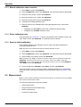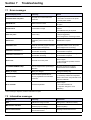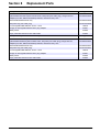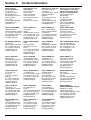
1
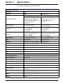
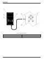
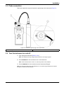
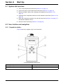
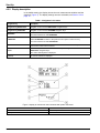
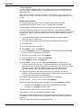
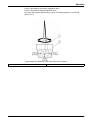
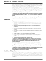
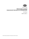
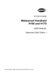
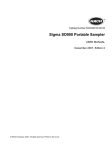
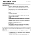
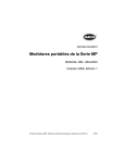
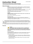
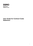
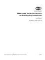
DOC023.53.90050
TSS Portable Handheld Instrument
for Turbidity/Suspended Solids
User Manual
September 2008, Edition 2
© HACH LANGE GmbH, 2004–2008. All rights reserved. Printed in Germany.
as/sd/sk
Table of Contents
Section 1 Specifications .................................................................................................................... 3
Section 2 General Information ......................................................................................................... 5
2.1 Safety information ........................................................................................................................ 5
2.1.1 Use of hazard information................................................................................................... 5
2.1.2 Precautionary labels ........................................................................................................... 5
2.2 Product overview ......................................................................................................................... 5
2.3 Measurement instrument ............................................................................................................. 5
2.4 Theory of operation...................................................................................................................... 6
2.5 Probe ........................................................................................................................................... 6
Section 3 Installation.......................................................................................................................... 7
3.1 Unpack the instrument ................................................................................................................. 7
3.2 Battery power (rechargeable batteries/standard batteries).......................................................... 7
3.2.1 Insert the batteries .............................................................................................................. 8
3.2.2 Charger for the rechargeable batteries ............................................................................... 9
3.2.3 Charge the batteries ........................................................................................................... 9
3.3 Probe connection ....................................................................................................................... 11
3.4 Turn the instrument on and off................................................................................................... 11
Section 4 Start Up ............................................................................................................................. 13
4.1 System start overview................................................................................................................ 13
4.2 User interface and navigation .................................................................................................... 13
4.2.1 Keypad description ........................................................................................................... 13
4.2.2 Display description............................................................................................................ 14
4.2.2.1 Internal probe information ........................................................................................ 15
4.3 Language selection.................................................................................................................... 15
4.4 Date and time setup................................................................................................................... 15
4.5 Display setup ............................................................................................................................. 16
4.6 Units setup ................................................................................................................................. 16
4.6.1 Sludge blanket level.......................................................................................................... 16
4.7 Calibration.................................................................................................................................. 16
4.8 Definition of the measurement points ........................................................................................ 17
4.8.1 Overview of measurement points and curves ................................................................... 17
4.8.2 Allocation to measurement points ..................................................................................... 17
4.8.3 Measurements .................................................................................................................. 18
4.8.3.1 Practical example for suspended solids measurement............................................ 18
4.8.3.2 Practical example for turbidity measurement ........................................................... 18
4.9 Integration time setup ................................................................................................................ 19
4.10 On time setup........................................................................................................................... 19
Section 5 Operation .......................................................................................................................... 21
5.1 Calibration.................................................................................................................................. 21
5.1.1 Special notes for calibration.............................................................................................. 21
5.1.2 Calibration procedure........................................................................................................ 21
5.1.3 Manual calibration value correction .................................................................................. 24
5.1.4 Delete calibration point ..................................................................................................... 24
5.1.5 Reset to default calibration ............................................................................................... 24
5.2 Measurement ............................................................................................................................. 24
5.2.1 Single measurement ......................................................................................................... 25
5.2.2 Single measurement with data storage............................................................................. 25
5.2.3 Interval measurement ....................................................................................................... 25
5.2.4 Continuous measurement................................................................................................. 26
5.2.4.1 Interrupt and restart the continuous measurement .................................................. 26
5.2.4.2 Stop the continuous measurement .......................................................................... 26
1
Table of Contents
5.3 Display the data..........................................................................................................................26
5.4 Delete data from a measurement point ......................................................................................27
5.5 Delete saved data from all measurement points ........................................................................27
Section 6 Maintenance .....................................................................................................................29
Section 7 Troubleshooting ..............................................................................................................30
7.1 Error messages ..........................................................................................................................30
7.2 Informative messages ................................................................................................................30
Section 8 Replacement Parts .........................................................................................................31
Section 9 Contact Information .......................................................................................................32
Section 10 Limited warranty ...........................................................................................................33
2
Section 1
Specifications
Specifications are subject to change without notice.
Performance specifications
Wavelength
860 nm
Parameter
Turbidity
Suspended Solids
Combined multiple-beam alternating light technique with IR diode system and beam focus
2-channel 90° scattered light
measurement in accordance with DIN
EN 27027 / ISO 7027; additional
measurement value verification through
six-channel multiple-angle
measurement
Modified absorption measurement
Six-channel multiple-angle
measurement
Measuring range
0.001–4.000 FNU (NTU)
0.001–400 g/L (upper limit depends on
sample characteristics)
Resolution
0.001 at 0–0.999 FNU
0.01 at 1–9.99 FNU
0.1 at 10–99.9 FNU
1 at >100 FNU
0.001 at 0–0.999 g/L
0.01 at 1–9.99 g/L
0.1 at 10–99.9 g/L
1 at >100 g/L
Accuracy
Measuring range: 0.001–4000 FNU
Accuracy of measurement value:
<3% or +/– 0.02 FNU
(whichever is greater)
Measuring range: 0.001–400 g/L
Accuracy of measurement value:
<4% or +/– 0.001 g/L
(whichever is greater)
Reproducibility
<4 % of measurement value
<5 % of measurement value
Units
FNU, NTU, EBC
ppm, mg/L, g/L, %
Calibration
1 calibration curve (factory calibration)
4 calibration curves
Mode of operation
Single, single with data storage, interval measurement and continuous measurement
Air-bubble compensation
Via software
Temperature of sample
0–60 °C (32–140 °F), up to 80 °C (176 °F) briefly
Pressure range
Max. 10 bar (145.04 psi)
Display
LCD, alphanumeric, 4 rows of 16 characters, 0.95 inch (24 mm) high, UV treated
Input
6 membrane key buttons, menu with fast access to the major functions
Power supply (batteries)
6 rechargeable NiMH batteries (recommended: 1.2 V/min. 1800 mAH) or 6 AA alkali batteries
Power consumption
Approx. 60 mA
Data storage
Up to 290 measurement values
Interface (probe to meter)
RS485
Probe material
Stainless steel, sensor window: sapphire
Cable
10 m (32.8 ft), PUR, ø 8.3 mm (0.33 in.); S-2000 connector, 6-pin
Protection class
Probe: IP68
Meter: IP 55
Size
Probe: ∅ 40 mm (1.57 in.), length = 29 cm (11.42 in.)
Meter: 11x23x4 cm (4.33x9.06x1.57 in.)
Weight
Probe: 1600 g (56.44 oz, 3.53 lbs)
Meter: 560 g (19.75 oz, 1.23 lbs)
Warranty
2 years
Measurement technique
3
Specifications
4
Section 2
General Information
2.1 Safety information
Read this entire manual before unpacking, setting up or operating this equipment. Pay
attention to all danger, warning and caution statements. Failure to do so could result in
serious injury to the operator or damage to the equipment.
Make sure that the protection provided by this instrument is not impaired, do not use or
install this instrument in any manner other than that specified in this user manual.
2.1.1 Use of hazard information
DANGER
Indicates a potentially or imminently hazardous situation which, if not avoided, will
result in death or serious injury.
WARNING
Indicates a potentially or imminently hazardous situation which, if not avoided,
could result in death or serious injury.
CAUTION
Indicates a potentially hazardous situation that may result in minor or moderate
injury.
Important Note: Indicates a situation which, if not avoided, may cause damage to the
instrument. Information that requires special emphasis.
Note: Information that supplements points in the main text.
2.1.2 Precautionary labels
Read all labels and tags attached to the instrument. Personal injury or damage to the
instrument could occur if not observed. A symbol, if noted on the instrument, will be
included with a danger or caution statement in the manual.
Electrical equipment marked with this symbol may not be disposed of in European public disposal systems after
12 August of 2005. In conformity with European local and national regulations (EU Directive 2002/96/EC),
European electrical equipment users must now return old or end-of life equipment to the Producer for disposal at no
charge to the user.
Note: For return for recycling, please contact the equipment producer or supplier for instructions on how to return
end-of-life equipment, producer-supplied electrical accessories, and all auxiliary items for proper disposal.
This symbol, if noted on the instrument, references the instruction manual for operation and/or safety information.
2.2 Product overview
The TSS Portable is a handheld instrument for the analytical determination of turbidity
and suspended solids in aqueous media.
2.3 Measurement instrument
The instrument stores the recorded data under the corresponding measurement points.
Standard designations, for example PST1 for primary sedimentation tank 1 or AT1 for
aeration tank 1, are available for selection.
For the turbidity/suspended solids measurements, a measurement-type-specific
calibration must be assigned to each measurement point. (Section 5.1 on page 21).
5
General Information
For the single measurement with "saving," the continuous measurement and the interval
measurement are saved with details of measurement type, measurement value, date and
time.
Various individual parameters for entering, signal processing and output can be set in the
menu (Section 4 on page 13).
2.4 Theory of operation
The measuring principle is based on a combined infrared absorption stray light process,
which determines the lowest turbidity value according to DIN EN 27027 just as precisely
and continuously as the high sludge content. In so doing, the light scattered sideways by
the turbidity particles are measured at an angle of 90°. In the case of solid material, the
measurement occurs at an angle of 90° and 120°.
2.5 Probe
The probe contains sensitive optical and electronic components. Make sure that it is not
subjected to any hard mechanical impacts. The inside of the probe, and of the display
unit, does not contain any components that can be serviced by the user.
6
Section 3
Installation
CAUTION
Risk of falling. Measurements are taken directly on site with this instrument. In
order to avoid falling into the tank, all the local safety regulations with respect to
roping up and wearing appropriate protective clothing and shoes must be
observed.
Risk of injury. Do not secure the instrument to your body. The measuring probe
could be caught unintentionally on a slide or stirrer and the user may be put at risk
by the connected probe cable.
WARNING
Electrical and fire hazards. Only qualified personnel should conduct the tasks
described in this section of the manual.
3.1 Unpack the instrument
Remove the instrument from the shipping container and inspect each part for damage.
Verify that all items listed in Figure 1 are included. If any items are missing or damaged,
contact the manufacturer or distributor.
Figure 1 Items supplied
1
TSS Portable handheld instrument
4
USA adapter plug
2
Probe with 10 m cable
5
UK adapter plug
3
Charger with EU adapter plug installed
6
AUS/China adapter plug
3.2 Battery power (rechargeable batteries/standard batteries)
DANGER
Risk of fire and explosion. Only use NiMH rechargeable batteries or AA alkali
batteries and make sure that the batteries are inserted correctly in the battery
compartment. Incorrect insertion of the batteries could lead to damage on the
instrument, to fire or explosions.
DANGER
Risk of fire and explosion. When using AA batteries, the instrument must never be
connected to the power supply.
7
Installation
The instrument is operated by six rechargeable or standard batteries (NiMH or alkali)
(Figure 2).
Important Note: Never use different rechargeable or standard battery types at the same
time.
Important Note: If the instrument is not to be used for a period of time, remove the
batteries.
3.2.1 Insert the batteries
1. Press in both catches at the same time and release the cover.
2. Take the battery holder out of the battery compartment (Figure 2).
3. Insert six rechargeable or standard batteries (NiMH or alkali) into the battery holder.
Take note of the markings for the polarity.
Important Note: Make sure that the batteries have been inserted into the battery
compartment correctly.
4. Connect the battery holder to the battery clip.
5. Push the battery holder into the battery compartment.
6. Push the cover onto the battery compartment, until it audibly locks into place.
Figure 2 Insert the batteries
1
Catch
4
Battery holder
2
Battery compartment
5
Batteries
3
Battery clip
6
Cover
8
Installation
3.2.2 Charger for the rechargeable batteries
1. Push the slide switch (item 2, Figure 3) on the back of the charger up and remove the
adapter (item 3, Figure 3).
2. Install the required adapter to the charger, until it audibly locks into place.
3. Insert the charging plug (item 3, Figure 4) into the charging socket (item 4, Figure 4)
of the instrument.
4. Connect the power (100–240 V~/50–60 Hz).
Figure 3 Replace the adapter
1
Charger
2
Slide switch
3
Remove the adapter
3.2.3 Charge the batteries
Important Note: The instrument must be switched off while charging so that the batteries
can be charged.
Important Note: When using the instrument for the first time, charge for at least three
hours. The batteries are fully charged when the LED on the charger is green.
1. When using NiMH rechargeable batteries, connect the charger to the power supply
and then connect to the instrument (Figure 4). The batteries are charged.
2. Once the batteries are fully charged, disconnect the instrument from the charger.
9
Installation
Figure 4 Charge the batteries
1
Charger
4
Charging socket
2
Discharge button (yellow)
5
LED lamp (green => batteries fully charged)
3
Charging plug
6
LED lamp (red => batteries currently charging)
10
Installation
3.3 Probe connection
Remove the protective cap and connect the probe plug to the instrument (Figure 5).
Figure 5 Connect the probe plug to the instrument
1
Probe plug
2
Probe connection
3.4 Turn the instrument on and off
1. Fully charge the instrument (Section 3.2.3).
Note: The batteries are fully charged when the LED on the charger is green.
2. Press ENTER/ON for two seconds to turn on the instrument.
Note: If the instrument does not turn on, check the position of the batteries.
3. Press CLEAR/OFF for two seconds to turn the instrument off again.
Note: The instrument shuts down automatically if it is not used for approximately four minutes
(exception: continuous measurement).
11
Installation
12
Section 4
Start Up
4.1 System start overview
1. Turn on the measurement instrument (Section 3.4 on page 11).
2. Connect the probe to the measurement instrument (Section 3.3 on page 11).
3. Edit the time/date, display, units, language and integration time (Section 4.3 on
page 15).
4. Calibration of the suspended solids in line with calibration instructions (Section 4.7 on
page 16).
5. Define the measurement points in line with the instructions (Section 4.8 on page 17)
and allocate calibration curves.
6. Show the data in the display (Section 5.3 on page 26).
4.2 User interface and navigation
4.2.1 Keypad description
Figure 6 shows the navigation keys on the instrument.
Figure 6 Description of the keypad
1
Navigation key UP
4
CLEAR/OFF
2
Navigation key RIGHT
5
Navigation key DOWN
3
ENTER/ON
6
Navigation key LEFT
13
Start Up
4.2.2 Display description
In the default setting, the display shows the main measurement variables and the
date/time (Figure 7). The display settings are user-selectable, see Section 4.5 on
page 16.
Table 1 Navigation in the menu
Navigation key
Description
Navigation key RIGHT/LEFT
Navigation occurs with the RIGHT/LEFT navigation keys.
Navigation key UP/DOWN
Navigation occurs with the UP/DOWN navigation keys.
ENTER/ON
- Confirm selection and entry with ENTER/ON.
- Turn the instrument on with ENTER/ON.
CLEAR/OFF
- Abort actions with CLEAR/OFF.
- Press CLEAR/OFF to return to the previous menu option or abort an entry.
- Turn the instrument off with CLEAR/OFF.
Vertical arrows
The vertical arrows in the display show that there are additional menu options or
measurement values above or below.
Cursor
- The cursor points to the selected main menu option. Navigation occurs with the
RIGHT/LEFT navigation keys.
- The active decimal place is displayed.
> (arrow)
The current selection is displayed
Figure 7 Display of results from the instrument with probe connected
1
Cursor
4
Current decimal place
2
Vertical arrows
5
Menu option
3
Input mode
6
Active selection
14
Start Up
4.2.2.1 Internal probe information
Information about the probe and instrument can be recalled directly from the main menu
using the navigation keys UP/DOWN.
The following information is displayed:
a. Measured variable (homogeneity in %)
b. Battery charge level
c. Diagnosis parameters, such as:
•
Probe serial number (instrument information)
•
Probe software version (instrument information)
•
Probe number Start XX (probe diagnosis data)
•
DATA rem. cap. XXX (Remaining capacity of the measurement points)
•
Fault no. XX
•
Activated measurement type
•
Serial no. XXXXX (instrument designation)
•
Software version XXXXX (instrument designation)
4.3 Language selection
The instrument supports the following languages, German and English. The instrument
functions in the selected language until the option is changed.
1. Select MENU, confirm with ENTER/ON.
2. Select SPRACHE/LANGUAGE, confirm with ENTER/ON.
3. Select DEUT./GERMAN for German or ENGL./ENGLISH for English, confirm with
ENTER/ON.
4. Press CLEAR/OFF, to return to the main menu.
4.4 Date and time setup
Set the time and date display:
1. Select MENU, confirm with ENTER/ON.
2. Select TIME/DATE, confirm with ENTER/ON.
3. Select YEAR, MONTH, DAY, HOUR, MINUTE or SECOND, confirm with ENTER/ON.
4. Select decimal places with the RIGHT/LEFT navigation keys.
5. Change the displayed value with the UP/DOWN navigation keys.
6. Confirm each setting with ENTER/ON.
7. Press CLEAR/OFF, to return to the MENU.
Note: Press CLEAR/OFF again to return to the main menu.
15
Start Up
4.5 Display setup
The first two lines of the display are user-selectable. In the default setting, the first row
shows the main measurement variable and the second row shows the date/time.
1. Select MENU, confirm with ENTER/ON.
2. Select DISPLAY, confirm with ENTER/ON.
3. Select LINE 1, confirm with ENTER/ON.
4. Select option for LINE 1, confirm with ENTER/ON.
•
Measurement value
•
Homogeneity
•
Battery
•
Time
5. Select LINE 2, confirm with ENTER/ON.
6. Select option for LINE 2, confirm with ENTER/ON.
7. Press CLEAR/OFF, to return to the MENU.
Note: Press CLEAR/OFF again to return to the main menu.
4.6 Units setup
The following measurement units are available for turbidity and suspended solids:
Turbidity units (TR): FNU, NTU, EBC
Suspended solids units (TS1 to TS4): ppm, mg/L, g/L, %
1. Select MENU, confirm with ENTER/ON.
2. Select UNITS, confirm with ENTER/ON.
3. Select Measurement type, confirm with ENTER/ON.
4. Select Measurement unit, confirm with ENTER/ON.
5. Press CLEAR/OFF, to return to the MENU.
Note: Press CLEAR/OFF again to return to the main menu.
4.6.1 Sludge blanket level
Sludge blanket level can be measured by setting the units to mg/L, g/L or %.
Calibrate your system, and then slowly lower the sensor into the clarifier. The suspended
solids concentration will significantly increase as it reaches the sludge blanket level.
Once the blanket level is reached, look at the the sensor cable which is marked every
meter to determine the sludge blanket level depth from the water surface.
4.7 Calibration
For turbidity measurement, a standard curve C-TU is already stored in the probe.
Calibration is not required, but this curve must be allocated to the desired measurement
point.
For suspended solids measurement, calibration is essential in order to set the rough
measurement signals to a calibrated display (refer to Section 5.1 on page 21). TSS
measurement is not possible without a valid measurement point definition or calibration.
There are four calibration curves available: C-DS1, C-DS2, C-DS3, C-DS4. These curves
can be allocated to the individual measurement points.
16
Start Up
4.8 Definition of the measurement points
4.8.1 Overview of measurement points and curves
Abbreviations available
on the instrument for measuring points
Abbreviations available
on the instrument for calibration curves
•
PST1 = Primary sedimentation tank 1
•
C-Tu = Turbidity curve (standard curve)
•
PST2 = Primary sedimentation tank 2
•
•
AT1 = Aeration tank 1
C-DS1 = Suspended solids curve (calibration
curve)
•
AT2 = Aeration tank 2
•
C-DS2 = Suspended solids curve (calibration
curve)
•
SST1 = Secondary sedimentation tank 1
•
•
SST2 = Secondary sedimentation tank 2
C-DS3 = Suspended solids curve (calibration
curve)
•
OutTu = Outlet turbidity
•
•
OutDS = Outlet dry substance
C-DS4 = Suspended solids curve (calibraiton
curve)
•
Dig-S = Digested sludge
•
Activ = Activated sludge
•
Turb = Turbidity
•
DS1 = Dry substance 1
•
DS2 = Dry substance 2
•
DS3 = Dry substance 3
•
DS4 = Dry substance 4
4.8.2 Allocation to measurement points
A calibration curve must be assigned to each measurement point. It is possible to assign
one curve to several measurement points.
Example: If a measurement is to be taken in aeration tank 1 and aeration tank 2, it is a
good idea to use the same curve if the media in the tanks are shown to have the same
qualities. Measurement points that are not required can be deactivated so that the
selection is smaller and the display is clearer. The measuring points are reactivated upon
reallocation.
1. Select MENU, confirm with ENTER/ON.
2. SELECT MEP-DEF., confirm with ENTER/ON.
3. Select measurement point (Section 4.8.3), confirm with ENTER/ON.
4. Select calibration curve (C-TU, C-DS1, C-DS2, C-DS3, C-DS4 or OFF), confirm with
ENTER/ON.
5. Press CLEAR/OFF, to return to the MENU.
Note: Press CLEAR/OFF again to return to the main menu.
17
Start Up
4.8.3 Measurements
4.8.3.1 Practical example for suspended solids measurement
Note: The type and composition of the solid particles of a medium can differ greatly. For this reason,
it is not possible to define a general standard, and different measurement media must be calibrated
specifically in each case.
Assumption: The measurement data of the measurements from two primary
sedimentation tanks and two secondary clarifiers should be saved for later evaluation. It
is assumed that the measurement medium in the two primary sedimentation tanks and in
the two secondary clarifiers have the same quality, and that only one calibration per stage
is required accordingly: Calibration curve 1 for the two primary sedimentation tanks and
calibration curve 2 for the two secondary clarifiers.
1. Define four measurement points on the instrument (refer to section 4.8.2 on page 17)
2. For example, activate measurement points PST1, PST2, SST1 and SST2:
Allocate calibration curve 1 (e.g. C-DS1) to PST1 and PST2, and calibration curve 2
(e.g. C-DS2) to SST1 and SST2.
3. Calibrate curves 1 and 2 (refer to section 5.1.2 on page 21)
4. Select the appropriate measurement points in the tanks and start the measurements.
The data will be automatically measured with the allocated calibration and saved at
the correct position. (refer to section 5.1.1 on page 21)
5. The data will be displayed under the measurement point with date and time (refer to
section 5.2 on page 24).
4.8.3.2 Practical example for turbidity measurement
A standardized turbidity curve is stored in the probe for turbidity measurement; calibration
is not necessary. Turbidity curve C-Tu must simply be allocated to the selected
measurement points.
18
Start Up
4.9 Integration time setup
Important Note: The integration time is only effective in the case of continuous
measurement. The values are averaged out during this time, which results in a smooth
measurement signal.
Upon delivery, the default value is set to 30 seconds. The integration time can be set to
between 0 and 1000 seconds.
1. Select MENU, confirm with ENTER/ON.
2. Select EXTRAS, confirm with ENTER/ON.
3. Select INTEGRATION, confirm with ENTER/ON.
4. Select decimal places with the RIGHT/LEFT navigation keys.
5. Change the displayed value with the UP/DOWN navigation keys.
6. Confirm each setting with ENTER/ON.
7. Press CLEAR/OFF, to return to the MENU.
Note: Press CLEAR/OFF again to return to the main menu.
4.10 On time setup
The on time allows the probe to reach a stable operating condition once a measurement
has been initiated. The measurement value is only generated toward the end of the set
time. The default setting of the on time is 5 seconds. Certain applications may require
more response time for more stability. The on time of 5–40 seconds is effective for the
following measurement modes:
•
Single measurement
•
Single measurement with data storage
•
Interval measurement (with automatic shut down)
1. Select MENU, confirm with ENTER/ON.
2. Select EXTRAS, confirm with ENTER/ON.
3. Select ON-TIME, confirm with ENTER/ON.
4. Select decimal places with the RIGHT/LEFT navigation keys.
5. Change the displayed value with the UP/DOWN navigation keys.
6. Confirm each setting with ENTER/ON.
7. Press CLEAR/OFF, to return to the MENU.
Note: Press CLEAR/OFF again to return to the main menu.
19
Start Up
20
Section 5
Operation
5.1 Calibration
Turbidity measurements do not need to be calibrated, as a standardized calibration curve
according to ISO 7027 is stored in the instrument. It is possible to create a
customer-specific calibration of the turbidity curve. If the standard curve has been altered,
a star (*) appears before the measurement point.
Suspended solids measurements must be calibrated on site. It is not possible to define a
general standard for this as the type and composition of the solid particles can differ
greatly.
5.1.1 Special notes for calibration
Calibration containers
In order to avoid reflections of the measurement beam on the base and walls of the
container, a black—or at the very least dark-colored—container should be used for
calibration.
The probe may also remain in the tank, so long as a representative laboratory sample
can be taken at this point.
Measured variable (homogeneity)
100% represents a homogeneous sample. After approximately 10 seconds, this
measured variable provides a representative statement about the homogeneity of the
measuring medium. The homogeneity is displayed as a percentage value after an
individual measurement (Figure 8).
Figure 8 Homogeneity in %
1
Homogeneity
Replace the probe
As the calibration is carried out for the measuring system (meter and probe), only the
probe supplied may be used for the measurements. If a different probe is used, the
equipment must be recalibrated.
Note: If the probe is replaced, the instrument reports "incorrect probe." Enter 390 in menu option
"System" using the navigation keys. This releases all the calibration curves for the suspended solids
measurement. Then the instrument needs to be recalibrated.
5.1.2 Calibration procedure
The instrument can save one turbidity curve and up to four suspended solids calibration
curves. This reduces the need for constant re-calibration for different locations or and/or
types of sludge. Each measurement location can have one of the saved calibration
curves assigned to it individually.
Note: During calibration, the automatic shut-down of the handheld instrument is deactivated.
21
Operation
1-point calibration
In order to define a calibration curve, it is generally sufficient to use a single calibration
point in the probe's measuring range. This should lie in the upper third of the expected
measuring range.
Note: If the measurement value is above or below the range defined by a point, the instrument
displays an error message: Calibration insufficient +/-. This means an additional calibration point is
required.
Multiple-point calibration
For a broad measuring range, a second calibration point must be recorded:
First calibration point (lower value) at as low a concentration as possible.
Second calibration point (upper value) at as high a concentration as possible.
Up to three calibration points per curve can be recorded. To record several calibration
points, the test sample is diluted or sedimented. Recorded calibration points are indicated
by a star (e.g. *point 1) and remain saved, even if the instrument is switched off in the
meantime.
1. Put a representative sample of the measuring medium into a black container.
Make sure that it is mixed evenly.
2. Use a part of this sample for the suspended solids analysis in the laboratory.
3. Clean the probe.
4. Insert the probe into the container.
5. Select MENU, confirm with ENTER/ON.
6. Select CALIBRATION, confirm with ENTER/ON. The instrument reads the probe data
and an informative text appears in the display.
7. Select the curve shown, confirm with ENTER/ON.
8. Select the desired curve, confirm with ENTER/ON.
9. Select MEMORY, confirm with ENTER/ON
10. Select POINT… (Point 1, 2 or 3), confirm with ENTER/ON. In so doing, stir the
measuring medium with the probe. The distance between the probe head and the
walls and base of the container must always be more than 70 mm (Figure 9). It takes
10 to 20 seconds to record the calibration point; then the selection menu for
calibration appears. While recording, the display shows the note "Memory."
11. Remove the probe from the container and clean it. If necessary, record more
calibration points with diluted or settled samples. Remove part of these samples for
the suspended solids analysis in the laboratory.
12. Determine the suspended solids of the sample(s) in the laboratory.
13. Select *Point… (*Point 1, 2 or 3), confirm with ENTER/ON.
14. Enter the laboratory value using the navigation keys, press ENTER/ON to confirm.
•
Navigation key LEFT/RIGHT: Jump to the next/previous decimal figure
•
Navigation key UP/DOWN: Change number
15. The laboratory value is saved. The main menu is shown.
Repeat steps 1 to 15 to record additional calibration points.
The instrument automatically sorts the saved calibration points according to the size of
the calibration values, irrespective of the sequence in which the calibration points were
recorded.
Point 1 is always allocated the lowest calibration value.
22
Operation
Point 2 is allocated the next higher calibration value.
Point 3 is allocated the highest calibration value.
The value determined in the laboratory can be corrected at anytime by overwriting
(refer to 5.1.3).
Figure 9 Minimum distances of the probe head in the container
1
Probe
2
Container
23
Operation
5.1.3 Manual calibration value correction
1. Select MENU, confirm with ENTER/ON.
2. Select CALIBRATION, confirm with ENTER/ON. The instrument reads the probe data.
3. Select the curve shown, confirm with ENTER/ON.
4. Select the desired curve, confirm with ENTER/ON.
5. Select the desired point, confirm with ENTER/ON.
6. Overwrite the existing calibration point.
7. Enter the value for the calibration point using the navigation keys, confirm with
ENTER/ON.
•
Navigation key LEFT/RIGHT: Jump to the next/previous decimal figure
•
Navigation key UP/DOWN: Change number
5.1.4 Delete calibration point
Same procedure as in section 5.1.3. Set the concentration of the calibration point to the
value 0.000, confirm with ENTER/ON. The calibration point is deleted.
5.1.5 Reset to default calibration
If the turbidity calibration was changed, it can be reset to the default calibration in
accordance with ISO 7027.
Note: Stop the current measurement before the default calibration is reset.
1. Select MENU, confirm with ENTER/ON.
2. Select CALIBRATION, confirm with ENTER/ON. The instrument reads the probe data.
3. Select turbidity curve C-TU, confirm with ENTER/ON.
Note: If turbidity curve C-TU is not shown in the menu, select the curve shown and confirm with
ENTER/ON. The selection menu for the curve is shown. Select curve C-TU, confirm with
ENTER/ON. Curve C-TU is activated. Open the selection menu for curve C-TU with ENTER/ON,
select RESET, confirm with ENTER/ON.
4. Press navigation key UP/DOWN, select RESET, confirm with ENTER/ON.
The reset function is not to be used to reset the suspended solids curves. Suspended
solids curves are reset when all calibration points are deleted. Refer to section 5.1.4 for
details.
5.2 Measurement
Note: In order to obtain suspended solids measurement results, the instrument must be calibrated
before the first measurement is taken.
The following measurement types are possible:
24
•
Single measurement
•
Single measurement with data storage
•
Interval measurement
•
Continuous measurement
Operation
5.2.1 Single measurement
No data is stored for the single measurement. The values are shown on the display.
1. Select MEAS, confirm with ENTER/ON.
2. Select SINGLE, confirm with ENTER/ON.
3. Select desired measurement point MEP:..., confirm with ENTER/ON. The
measurement points available for selection are those that are activated in the
measurement point definition (menu option MEP-DEF.).
4. Select MEASURE NOW, confirm with ENTER/ON.
5. Read off the measurement value from the display.
5.2.2 Single measurement with data storage
With selecting single measurement with data storage, the displayed results can be stored
if required.
1. Select MEAS, confirm with ENTER/ON.
2. Select SINGLE+SAVE, confirm with ENTER/ON.
3. Select desired measurement point MEP:..., confirm with ENTER/ON. The
measurement points available for selection are those that are activated in the
measurement point definition (menu option MEP-DEF.).
4. Select MEASURE NOW, confirm with ENTER/ON.
5. Select YES or NO, confirm with ENTER/ON.
6. After the measurement is taken, save and confirm with ENTER/ON.
Note: Selecting NO will abort the saving procedure.
5.2.3 Interval measurement
On interval measurement, the data is measured at certain intervals. As soon as the
interval period has been reached, the instrument starts automatically, saves the current
measurement value and switches back to standby (power save) mode. This means that
the display also goes out.
1. Select MEAS, confirm with ENTER/ON.
2. Select INTERVAL, confirm with ENTER/ON.
3. Select desired measurement point MEP:..., confirm with ENTER/ON. The
measurement points available for selection are those that are activated in the
measurement point definition (menu option MEP-DEF.).
4. Select INTERVAL and set the time interval (1/2/3/4/5/6/10/12/15/20/30/60 minutes) for
the measurements.
5. Enter the interval using the navigation keys, confirm with ENTER/ON.
•
Navigation key LEFT/RIGHT: Jump to the next/previous decimal figure
•
Navigation key UP/DOWN: Change number
6. Select MEASURE NOW, confirm with ENTER/ON. After measuring, the instrument
switches into standby mode.
25
Operation
Suspend standby mode/interval measurement
1. Turn on the instrument with ENTER/ON. Scrolling text on the display shows that an
interval measurement is taking place.
2. Select MEAS, confirm with ENTER/ON.
3. Select STOP, confirm with ENTER/ON.
5.2.4 Continuous measurement
On continuous measurement, measurements are taken continuously, and the current
measurement value is saved at intervals.
1. Select MEAS, confirm with ENTER/ON.
2. Select CONTINUOUS, confirm with ENTER/ON.
3. Select desired measurement point MEP:..., confirm with ENTER/ON. The
measurement points available for selection are those that are activated in the
measurement point definition (menu option MEP-DEF.).
4. Select INTERVAL, confirm with ENTER/ON.
5. Enter the interval using the navigation keys, confirm with ENTER/ON.
•
Navigation key LEFT/RIGHT: Jump to the next/previous decimal figure
•
Navigation key UP/DOWN: Change number
6. Select MEASURE NOW, confirm with ENTER/ON.
7. Read off the measurement value from the display.
5.2.4.1 Interrupt and restart the continuous measurement
1. Press CLEAR/OFF for two seconds. The instrument switches off and the continuous
measurement is suspended.
2. Press ENTER/ON for two seconds. The instrument switches on and the continuous
measurement continues with the same settings as before the instrument was
switched off.
5.2.4.2 Stop the continuous measurement
1. Select MEAS, confirm with ENTER/ON.
2. Select STOP, confirm with ENTER/ON.
5.3 Display the data
The display shows the stored data for the measurement points.
1. Select DATA, confirm with ENTER/ON.
2. Select desired measurement point MEP:..., confirm with ENTER/ON. Only those
measurement points are displayed, which contain saved data.
3. Select DISPLAY MEP, confirm with ENTER/ON. The data is shown in the display.
4. Display additional data with ENTER/ON.
26
Operation
5.4 Delete data from a measurement point
1. Select DATA, confirm with ENTER/ON.
2. Select desired measurement point MEP:..., confirm with ENTER/ON. Only those
measurement points are displayed, which contain saved data.
3. Select DELETE MEP, confirm with ENTER/ON.
4. Select YES, confirm with ENTER/ON.
Note: NO aborts the erasing procedure.
5.5 Delete saved data from all measurement points
1. Select MENU, confirm with ENTER/ON.
2. Select SYSTEM, confirm with ENTER/ON.
3. Set the value in the System menu to 379 using the navigation keys, confirm with
ENTER/ON.
27
Operation
28
Section 6
Maintenance
The cleanliness of the measurement windows in probe is important to maintain accurate
readings!
Cleaning the measurement windows
The windows are made of sapphire glass. If required, they can be cleaned with any
conventional cleaning agent and a soft cloth. In the case of stubborn deposits, wipe it with
a soft cloth soaked in the 5% hydrochloric acid.
WARNING: Observe safety conditions and wear protective clothing!
•
Safety glasses
•
Gloves
•
Overalls
29
Section 7
Troubleshooting
7.1 Error messages
Problem/display screen
Caused by
Action
Communication with probe
The probe is not connected to the
instrument
- Plug in the probe
- Check the connection to the probe
- Correct probe number
EEPROM error
Values cannot be saved
Switch the instrument off and then back
on again
Overflow area
Concentration too high
- Probe is measuring in an unsuitable
medium
- Recalibration may be required
Clean the probe
Probe is dirty
- Clean the probe
- May be triggered by
non-homogeneous measuring medium
Offset error
Calibration point set incorrectly
(calibration point too close to the zero
point)
Recalibration required
Calibration error
No calibration available, calibration
points set incorrectly (upper and lower
calibration points transposed)
Recalibration required. (There is no
suspended solids curve in the probe
when shipped from the factory)
Calibration insufficient ->–
Additional calibration point with lower
concentration is missing
Additional calibration point with lower
concentration is required
Calibration insufficient ->+
Additional calibration point with higher
concentration is missing
Additional calibration point with greater
concentration is required
Probe error
Technical error in the probe
- Switch the instrument off and then
back on again
- If the message is repeated, send the
probe for repair
First MEASUREMENT=Stop
Continuous or interval measurement
was not stopped before performing a
calibration
Stop the continuous or interval
measurement before calibration
Battery is empty
Battery not charged
Charge the battery fully
Incorrect probe
Probe has been replaced but not
correctly registered to the handheld
instrument
- Connect the correct probe
- If necessary, release the suspended
solids curve for the new probe with Code
390 and recalibrate
Time/date implausible
- Switch the instrument off and then
back on again
- Check the time/date set
- If required, change the clock
batteries1)
Error time/date
1 If
the message is repeated, send the instrument for repair
7.2 Informative messages
Display screen
Caused by
Action/Note
Wait
Calibration is being recorded
Wait (probe in calibration medium)
Manufacturer standard
Measurement value is outside the
standard (only for turbidity)
Value is above the DIN standard of
4000 FNU (NTU)
Interval measurement...
The instrument is carrying out an
interval measurement
Ongoing interval measurement
30
Section 8
Replacement Parts
Description – Replacement Parts for Amrica and Asia
Catalog number
TSS Portable hand-held system
(TSS Portable hand-held system includes meter, TSS probe (10m cable, plug), charger with four
adapters (ES, USA, GB and AUS/China) batteries, manual and carry case
LXV322.99.00002
TSS Portable handheld meter only
LXV320.99.00002
TSS probe only (10m cable, plug)
LXV321.99.00002
6 x rechargeable NiMH batteries, AA min. 1.8 Ah
LZY604
Charger for rechargeable batteries with 4 plug adapters
LZY607
Battery holder
LZY606
Empty, hard-sided instrument case with handle
LZY605
Description – Replacement Parts for Europe and North Africa
Catalog number
TSS Portable hand-held system
(TSS Portable handheld system includes meter, TSS probe (10m cable, plug), charger with four
adapters (ES, USA, GB and AUS/China) batteries, manual and carry case
LXV322.99.00001
TSS Portable handheld meter only
LXV320.99.00001
TSS probe only (10m cable, plug)
LXV321.99.00001
6 x rechargeable NiMH batteries, AA min. 1.8 Ah
LZY604
Charger for rechargeable batteries with 4 plug adapters
LZY607
Battery holder
LZY606
Empty, hard-sided instrument case with handle
LZY605
31
Section 9
Contact Information
HACH Company
World Headquarters
P.O. Box 389
Loveland, Colorado
80539-0389 U.S.A.
Tel 001 (800) 227-HACH
(800) -227-4224
(U.S.A. only)
Fax 001 (970) 669-2932
[email protected]
www.hach.com
Repair Service in the
United States:
HACH Company
Ames Service
100 Dayton Avenue
Ames, Iowa 50010
Tel 001 (800) 227-4224
(U.S.A. only)
Fax 001 (515) 232-3835
Repair Service in Canada:
Hach Sales & Service
Canada Ltd.
1313 Border Street, Unit 34
Winnipeg, Manitoba
R3H 0X4
Tel 001 (800) 665-7635
(Canada only)
Tel 001 (204) 632-5598
Fax 001 (204) 694-5134
[email protected]
Repair Service in Latin America,
the Caribbean, the Far East,
Indian Subcontinent, Africa,
Europe, or the Middle East:
Hach Company World
Headquarters,
P.O. Box 389
Loveland, Colorado,
80539-0389 U.S.A.
Tel 001 (970) 669-3050
Fax 001 (970) 669-2932
[email protected]
HACH LANGE GMBH
Willstätterstraße 11
40549 Düsseldorf, Germany
Tel. +49 (0)2 11 52 88-320
Fax +49 (0)2 11 52 88-210
[email protected]
www.hach-lange.de
HACH LANGE LTD
Pacific Way
Salford
GB-Manchester, M50 1DL
Tel. +44 (0)161 872 14 87
Fax +44 (0)161 848 73 24
[email protected]
www.hach-lange.co.uk
HACH LANGE LTD
Unit 1, Chestnut Road
Western Industrial Estate
IRL-Dublin 12
Tel. +353(0)1 46 02 5 22
Fax +353(0)1 4 50 93 37
[email protected]
www.hach-lange.ie
HACH LANGE GMBH
Hütteldorferstr. 299/Top 6
1140 Wien, Austria
Tel. +43 (0)1 9 12 16 92
Fax +43 (0)1 9 12 16 92-99
[email protected]
www.hach-lange.at
DR. BRUNO LANGE AG
Juchstrasse 1
8604 Hegnau, Switzerland
Tel. +41(0)44 9 45 66 10
Fax +41(0)44 9 45 66 76
[email protected]
www.hach-lange.ch
HACH LANGE FRANCE
S.A.S.
33, Rue du Ballon
93165 Noisy Le Grand,
France
Tel. +33 (0)1 48 15 68 70
Fax +33 (0)1 48 15 80 00
[email protected]
www.hach-lange.fr
HACH LANGE SA
Motstraat 54
2800 Mechelen, Belgium
Tel. +32 (0)15 42 35 00
Fax +32 (0)15 41 61 20
[email protected]
www.hach-lange.be
DR. LANGE NEDERLAND B.V.
Laan van Westroijen 2a
4003 AZ Tiel, Netherlands
Tel. +31(0)344 63 11 30
Fax +31(0)344 63 11 50
[email protected]
www.hach-lange.nl
HACH LANGE APS
Åkandevej 21
2700 Brønshøj, Denmark
Tel. +45 36 77 29 11
Fax +45 36 77 49 11
[email protected]
www.hach-lange.dk
HACH LANGE AB
Vinthundsvägen 159A
128 62 Sköndal, Sweden
Tel. +46 (0)8 7 98 05 00
Fax +46 (0)8 7 98 05 30
[email protected]
www.hach-lange.se
HACH LANGE S.R.L.
Via Riccione, 14
20156 Milano, Italy
Tel. +39 02 39 23 14-1
Fax +39 02 39 23 14-39
[email protected]
www.hach-lange.it
HACH LANGE S.L.U.
Edif. Arteaga Centrum
C/Larrauri, 1C- 2ª Pl.
48160 Derio/Vizcaya, Spain
Tel. +34 94 657 33 88
Fax +34 94 657 33 97
[email protected]
www.hach-lange.es
HACH LANGE LDA
Av. do Forte nº8
Fracção M
2790-072 Carnaxide,
Portugal
Tel. +351 214 253 420
Fax +351 214 253 429
[email protected]
www.hach-lange.pt
HACH LANGE SP.ZO.O.
ul. Opolska 143 a
PL-52-013 Wrocław, Poland
Tel. +48 (0)71 342 10-83
Fax +48 (0)71 342 10-79
[email protected]
www.hach-lange.pl
HACH LANGE S.R.O.
Lešanská 2a/1176
141 00 Praha 4,
Czech Republic
Tel. +420 272 12 45 45
Fax +420 272 12 45 46
[email protected]
www.hach-lange.cz
HACH LANGE S.R.O.
Roľnícka 21
831 07 Bratislava – Vajnory,
Slovakia
Tel. +421 (0)2 4820 9091
Fax +421 (0)2 4820 9093
[email protected]
www.hach-lange.sk
HACH LANGE KFT.
Hegyalja út 7-13.
1016 Budapest, Hungary
Tel. +36 (06)1 225 7783
Fax +36 (06)1 225 7784
[email protected]
www.hach-lange.hu
HACH LANGE S.R.L.
Str. Căminului nr. 3
Sector 2
021741 Bucureşti, Romania
Tel. +40 (0) 21 205 30 03
Fax +40 (0) 21 205 30 03
[email protected]
www.hach-lange.ro
HACH LANGE
8, Kr. Sarafov str.
1164 Sofia, Bulgaria
Tel. +359 (0)2 963 44 54
Fax +359 (0)2 866 04 47
[email protected]
www.hach-lange.bg
HACH LANGE D.O.O.
Fajfarjeva 15
1230 Domžale, Slovenia
Tel. +386 (0)59 051 000
Fax +386 (0)59 051 010
[email protected]
www.hach-lange.si
ΗΑCH LANGE E.Π.Ε.
Αυλίδος 27
115 27 Αθήνα, Greece
Τηλ. +30 210 7777038
Fax +30 210 7777976
[email protected]
www.hach-lange.gr
HACH LANGE E.P.E.
27, Avlidos str
115 27 Athens, Greece
Tel. +30 210 7777038
Fax +30 210 7777976
[email protected]
www.hach-lange.gr
HACH LANGE SU
ANALİZ SİSTEMLERİ LTD.ŞTİ.
Hilal Mah. 75. Sokak
Arman Plaza No: 9/A
06550 Çankaya/ANKARA, Turkey
Tel. +90 (0)312 440 98 98
Fax +90 (0)312 442 11 01
[email protected]
www.hach-lange.com.tr
32
Section 10
Limited warranty
Hach Company warrants its products to the original purchaser against any defects
that are due to faulty material or workmanship for a period of one year from date
of shipment unless otherwise noted in the product manual.
In the event that a defect is discovered during the warranty period, Hach
Company agrees that, at its option, it will repair or replace the defective product or
refund the purchase price excluding original shipping and handling charges. Any
product repaired or replaced under this warranty will be warranted only for the
remainder of the original product warranty period.
This warranty does not apply to consumable products such as chemical reagents;
or consumable components of a product, such as, but not limited to, lamps and
tubing.
Contact Hach Company or your distributor to initiate warranty support. Products
may not be returned without authorization from Hach Company.
Limitations
This warranty does not cover:
•
Damage caused by acts of God, natural disaster, labor unrest, acts of war
(declared or undeclared), terrorism, civil strife or acts of any governmental
jurisdiction
•
Damage caused by misuse, neglect, accident or improper application or
installation
•
Damage caused by any repair or attempted repair not authorized by Hach
Company
•
Any product not used in accordance with the instructions furnished by Hach
Company
•
Freight charges to return merchandise to Hach Company
•
Freight charges on expedited or express shipment of warranted parts or
product
•
Travel fees associated with on-site warranty repair
This warranty contains the sole express warranty made by Hach Company in
connection with its products. All implied warranties, including without limitation,
the warranties of merchantability and fitness for a particular purpose, are
expressly disclaimed.
Some states within the United States do not allow the disclaimer of implied
warranties and if this is true in your state the above limitation may not apply to
you. This warranty gives you specific rights, and you may also have other rights
that vary from state to state.
This warranty constitutes the final, complete, and exclusive statement of warranty
terms and no person is authorized to make any other warranties or
representations on behalf of Hach Company.
Limitation of Remedies
The remedies of repair, replacement or refund of purchase price as stated above
are the exclusive remedies for the breach of this warranty. On the basis of strict
liability or under any other legal theory, in no event shall Hach Company be liable
for any incidental or consequential damages of any kind for breach of warranty or
negligence.
33
Limited warranty
34