1
United States Patent [191
[11]
[45]
Mark
[54] AUTOMATIC IRRIGATION WATER
Arnold Mark, 2485 Malibu Rd.,
Bellmore, N.Y. 11710
Field of Search ............. .. 364/420, 509, 510, 138,
364/141, 152, 153; 340/604, 602; 73/73, 74, 77;
137/624,l8, 624.2; 239/63, 71
364/420
irrigation system cycles, the water conservation device
senses the moisture compares it with the wet and dry
readings and scales back the amount of water applied to
the ground area.
364/510
4,189,776
364/510
Kendall ..................... ..
4,423,484 12/1983 Hamilton .
4,567,563
1/1986
4,569,020
2/1986 Snoddy et a1. ..
4,626,984 12/1986 Unruh et al.
4,646,224 2/ 1987 Ransburg et al.
364/420
364/420
4,799,142
I/ 1989
Hirsch ....... ..
vice senses the moisture in the soil and compares it with
preset wet and dry moisture limits and scales back each
of the watering cycles in proportion to the moisture
content of the ground to thereby conserve irrigation
364/510
Kendall et a1. ................... .. 364/510
4,176,395 11/1979 Evelyn-Veere et a1.
2/1979
limit the flow of water during timed irrigation cycles.
When the timed watering cycles are initiated by the
standard irrigation system, the water conservation de
364/420
U.S. PATENT DOCUMENTS
8/1979
A water conservation system that connects between a
water that is applied to a ground area. The device in
cludes a moisture sensor, a central processing unit, and
a solid state memory that is connected to the central
processing unit and the moisture sensor. When the de
vice of the invention is initialized, the solid state mem
ory samples and records the wet and dry moisture read
ings of the ground zone and stores the resultant wet and
dry readings in the memory so that each time the timed
References Cited
4,165,532
ABSTRACI‘
standard irrigation system that is controlled by a clock,
Int. (31.5 .................... .. G06F15/46;AO1G 25/16
us. or. .................................. .. 364/510; 364/420;
[56]
[57]
and the water control valves of that system in order to
364/141; 364/153; 340/602; 73/73; 137/6242;
239/63; 239/71
[58]
May 1, 1990
Assistant Examiner-Brian M. Mattson
[21] Appl. No.: 137,457
[22] Filed:
Dec.23,1987
[51]
[52]
4,922,433
Attorney, Agent, or Firm-Collard, Roe & Galgano
CONSERVATION CONTROLLER
[76] Inventor:
Patent Number:
Date of Patent:
Waltzer et a1. ................... .. 364/420
Primary Examiner—-Parshotam S. Lall
DURATlON SETTINGS
0000000
12 34 s e rzoue
15 Claims, 15 Drawing Sheets
US. Patent
May 1,1990
Sheet 1 0f 15
4,922,433
.?
LL.
2w0o.z5CLm
OQ
_¢wwzos.
N
m
4
A
SET STACK
POINTER
‘Sheet 3 0f 15
May 1, 1990
Patent
4,922,433
IS
RESPONSE
5|
_/
VALID?
TO DO?
YES
SET ALIZONES TO
INITIAL
"OF-F" STATE
VARIABLES
CHANGE
PROCESSOR
CONTROL
WORD (PCWI
CLEAR
R
lN'lf'riAFéUF’T
ARE
THERE VALID
/MOISTURE
READINGS ?
IS IT BEGINING,
OF A ‘CYCLE .7
LEARNING PHASE
COMACTS
A SET
UP FoR
_ SELF TEST
53
(RAM
STDRE
..
TEST)
b DRYREADING
CHECKER BOARD
54
TEST FoRwARD
L
AND REVERSE
PATTERNS
+
"TURN,
OFF
SENSOR
..
YES
CALL ONE
SECOND DELAY
ROUTINE
I
CALLINCREMENT
DURATION
COUNTERS
ROUTINE
I
~
DID
RAM TEST
PASS?
Chit“
RAM
LOCATIONS
;
SECOND
DELAY
ROUTINE
“"15 OUT
MANDATORY
BYPASS
MODE
CALL ONE
5i
INPUT
zoNE
FLAGS
INPUT
ZONE
FLAGS
I
MASK
BYPASS
FLAG
I
TU RN
MASK
"0N"
BYPASS
SENSOR
FLAG
CALL
A/D AND
AVERAGING
ROUTINE
cALL
VALIDATE
RESPONSE
ROUTINE
I
Fig. 3A
CALL
VA LI DATE
RESPONSE .
ROUTINE
US. Patent
May 1,1990
Sheet 4 of 15
;
‘
IS RESPONSE
I NEW WORD ?
SET UP
20
{a}
TIMER
J
'V
CALL
4,922,433
1
ONE
'
SECOND
UPDATE
~
Pcw AND
DELAY
WATERED
ROUTINE
I
WORDS
CALL INCREMENT
DURATION
COUNTERS
_
_
ROUTINE
YES
Is ZONE
[———--I- —--|
DECREMENT
QFLAG
STILL II ON II '5
I
20
MINUTE
I_ _
TIMER
.
_
_
__
_
2251“ BI'ITLRR '
MINUTES
ELA PSED ?
,
_
wET sue ROUTINE 7
‘
L
_
—
_
@
_
_
"1N0
_
_
II
"
AVERT 8 LINEAR-
I
IBISVREIZE
IZATION ROUTINE
i
READlNG VALID
_
_
_
_
_
'
COMPARED
TO "DRY" ?
YES
CALL INCREMENT
DURATION
COUNTERS
M A SK
BYPASS
FLAG
sToRE"wET"
MOISTURE
READING TURN
ROUTINE
"OFF" SENSOR
I
I
CALL ONE
SECOND
-CALL
VALIDATE
DELAY
.
RESPONSE
ROUTINE
NO
ROUTINE
IS
RESPONSE
'
ALID?
IS THERE VALID
"WET" READING
Fig. 3B
US. Patent
MASK
May 1, 1990
Sheet 5 of 15
4,922,433
UPDATE
PCW AND
WATERED
woRDs
ZONE 0
FLAG
I
IS "WET" MOISTURE
I __
UPDATE
PCW
WORD
READING VALID '2
NO
CALL ONE
SET LEARNING
SECOND
,
>
PHASE
DELAY
ROUTINE
IS "WET" READING
COMPLETE
VARIABLE
I
VA LID COMPARED
I
TO DRY ?
CALL
WETSUB
ROUTINE
INITIALIZE
VARIABLES
NO
YES
No
I.
INPUT
‘ZONE
FLAGS
YES
I
\HAS 2o
INPUT
ZONE
FLAGS
MINUTES
ELAPSED 2)
VALIDATE
RESPONSE
I
MASK ZONE
6 AND
BYPASS
FLAGS
IS
RESPONSE
I
CALL
VALIDATE
RESPONSE
ROUTINE
IS
RES PONSE
VALID?
YES
UPDATE
PCW
WORD
IS RESPONSE
NEW WORD ?
NO
HAS ZONE
0 FLAG
TURNED'HON'I ?
Fig. 3C
IiI
US. Patent
May 1,1990
Sheet 6 of 15
‘
4,922,433
GFAS€MEEw — — _®
_ __|
I
I
SET PCW a
WATERED
WORDS
UPDATE
Pow
wORD
I
To
I
I
TURN"ON"sENsOR
CALL A/D INPUT
AvERT @- LINEARIZATION ROUTINE
CALL ONE
SECOND
DELAY
ROUTINE
I
I
sTORE'PREsENT
I
MOISTURE
BIEADIIIIVG TURN
VALIDATE
RESPQNSE
OFF sENsOR
I
CALL CALCULATE
I
ls
DFISSIISENS
I
REsPONsE
‘FOR ALL zONEs
I
I
@
I
PCW
I
Is ZONE 0
WORD
|
FLAG "OFF" 2
UPDATE
5
I
CALL ONE
IS PCW
WORD
I
I
SDEECI-ZQID
ROUTINE
,
OON?
@ .
CLEAR
..
ZOHNE Q
OFF
wORO
.
I
I
I
I
YEs
NO
CA'LL
DECREMENT
ROUTINE
HAVE ANY _
I
IT'MERSI
ZONES TIMED
OUT 2 ‘
NO
I
I
Is THIS
BEGINING OF /
I WATERED
CYCLE 2
I
I
YEs
REMOVE ZONE
.
Fig. 3D
FROM PCW a
sET BIT IN
wATEREO
I
I
I
l
IS ZONE O
WORD CLEARED ?
US. Patent
May 1,1990
Sheet 7 of 15
4,922,433
WINTER-R115‘? _ _'
|ROUTINES
I
|
|
| ;
I
SET UP
I‘
INITIAL
I ITE T
|
VARIABLES
I
VARIABLES
I l
I
I-___
o?é‘é-Ec
-
ROUTINE,
FLAGS
YES
I
‘
I
CALL | SEC.
SEITHOZQQF
‘I
(2 TIMES)
'
I
I
I
WORD_AAN
I
INPUT
@
I
I" ‘_ _' "_ -—1
II @ I
I I
FOR SWITCH
| l
DEBOUNCING
I
~
I
ROUTINE
'
USED FOR
I
PRODUCTION
TESTING
I
I
I
cI_EAR
|
SET RETURN
ADDRESS
I |
WORD
I
RESETTER
I L _ _- _-----l
'
|
I
NO
I
IS IT START
OF NEW CYCLE 2
I'- '- — .— —I 4
LEARN RESET
Fig. 3E _
. |
I
US. Patent
May 1, 1990
Sheet 8 of 15
4,922,433
@
CALCULATE
ZONE
GET DURATION
FOR ZONES
OUT OF
TABLE
DURATIONS
is
T
YES
M ULTIPLIER
MULTIPLIER
PRESENTS
= DURATION
T
IS
PRESENTZ
MULTIPLIER
=0
YES
MULTIPLIER
x (8 BITS)
.
MULTIPLIER
(I6 BITS)
PRODUCT '1'
MULTIPLIER
I24 BITS)
BY DIVISOR
I8 BITS)
= PRESENT
-DRY
L
r
GET INDEX
INTO
COUNTER
DIVISOR
=WET
~DRY
T
T
COUNTER=
QUOTIENT
(I6 BITS)
REG 8=7
I# ZONES)
STORE
INDEX
INTO
COUNTER
TABLE
T
STORE INDEX
INTO
DURATION
TABLE
Fig. 4
Z
INCREMENT
COUNTER
INDEX
BY 2
INCREMENT
DURATION
INDEX
BY 2
Fig. 5
DECREMENT
,
REG B
# ZONES
US. Patent
May 1, 1990
Sheet 9 of 15
@
DECREMENT
SAVE
IAcc 8)
20 MINUTE
TIMER
ON STACK
D
HAS 20 MIN.
ELAPSED ?
NO
LOAD LAST
RESPONSE
INTO
Acc B
IS TIMER I5
SEC. REMAIN. ?
I
TURN
ON
SENSOR
TURN
OFF
SENSOR
4,922,433
UPDATE LAST
RESPONSE W.
PRESRESPONSE
(Acc A)
CL
R
EA
Acc B
.___I
RESTORE
Acc B
Um
Fig. 7
EXIT
Fig. IO'
US. Patent
May 1, 1990
4,922,433
Sheet 10 of 15
(i9
SAVE
Acc A,B
AND INDEX
T
DE LAY
‘ | SEC.
(LOOP)
RESTORE
IN DEX
T
LOAD PCW
COMPARTMENT
Pow TURN
ON ON LED
YES
NO
OUTPUT TO
PORT l
PCWREG
OUTPUT 2
PUMP
OUTPUT TO
'
PORT 2
RESTORE
Acc A,B
Fig. 9
@EXIT
US. Patent
May 1, 1990
4,922,433
Sheet 11 0f 15
@
PRODUCT
=0
24 BITS
NEED TO BE
TIMED
=PC WATERED
REG
ANY ZONES
NEED TO
BE TIMED ?
GET
MULTIPLIER
NO
YES
GET BASE
PRODUCT=
MULTIPLIER
MULTIPLIER
LOOP
COUNTER
MASK
MULTIPLIER
TO BE TIMED ?
UEXIT
SHIFT
MU LTIPLIER
RIGHT l BIT
INTO CARRY
DECREMENT
TIME COUNT
FOR
ZONE N
DECR‘EMENT
LOOP
COUNTER
HAVE ALL
ZONES BEEN ADD
MULTIPLIER
TO PARTIAL
PRODUCT
4
k_—.
MU LTI PLY
MULTIPLIER
BY 2
___|
UPDATED ?
YES
NO
US. Patent
May 1,1990
Sheet 12 of 15
4,922,433
DECREMENT
,
ZONE
LEFT SHIFT
CARRY INTO
NEWVfQTE-R
NEWWATER
-
18855???
DECREMENT
INDEX
§Ei___
BY 2
PCW'WATERED
sToRE
- igggeggm
INDEX INTO
_,
.
COUNTER
TABLE
1s
NO
ZONECOUNT
ZONECOUNT
=
Y
UPDATE
BITNUM
WATERED BY
B|TNUM=
WATERED+
NEWWATER
BITNUM+I
:
UPDATE
PCW BY
PCW=
Pcw-N—Eww—ATER"
EX'T
COUNTER=
COUNTER-l
Fig‘
NO
CLEAR
CARRY
BIT
YEs
SET
CARRY
BIT
US. Patent
May 1,1990
Sheét 13 (‘)f 15
@
GET PCWREG
AND SAVE
ON STACK
MASK OUT
ZONE D AND
RESTORE
PCWREG
AVERAGE
MOISTURE
READING
GLEAR
Acc A,Ia
I_oAD LOOP
COUNTER
sAvE AvER.
MOISTURE
READING
IN AccA
' SEND sTART
RESTORE
cuRRENT
PCWREG
woRD
GoNvERsIoN
To A/D
CALL
EXIT
ONE SEC.‘
GET
MOISTURE
READING
FIg. 13
ADD IT TO
PREVIOUS
MOISTURE
READING
DECREMENT
LOOP
COUNTER
NO
YES
HAVE WE
TAKEN 4
READINGS ?
4,922,433
US. Patent R
May 1,1990
4,922,433
Sheet 14 0f 15
@
SET
REMAIN DER
EQUAL
ZERO
-- REMAINDER
FROM DIVISOR
RESULT=A
YES
NO
SET
QUOTIENT
TO I
'
QUOTIENT
=00
REMA
v
IS REMAINDER
I/Z DIVISOR ?
YES
‘
HAVE WE
SHIFTED
.24 TIMES 2
IS/QUOTIENT NO
(I 20 SECS '?
ADD ONE
TO QUOTIENT
EXIT
US. Patent
May 1,1990
Sheet 15 of 15
4,922,433
E
LOAD
LOOP
COUNTER
sAvE A
COPY OF
RESPONSE
LOAD
MASK
49H
4
L
IS ZONE "N" ON
IN RESPONSE WORD 2
ADD JUST
TURNED OFF
ZONE TO
-
WATERED
'
TAKE
ADP “ZONE
our IINII
OF
PCWREG
N
PCWILREG
I
"
HAS ZONE '_'N"
DECREMENT
LooP
COUNTER
JUST TURNED OFF 2
HAVE ALL ZONE‘S
BEEN CHECKED ‘.7
Y
Es
EXIT‘
I
ADJUST
MASK
1
4,922,433
2
A common problem with the two conventional sys
tems described above is their inability to compensate for
AUTOMATIC IRRIGATION WATER
CONSERVATION CONTROLLER
water settling time. During the watering cycle, the
sensor receives a premature saturation reading due to
The present invention relates to a control system for 5 the fact that the water saturates the soil around the
sensor very quickly after the sprinkler system is turned
water irrigation and, more particularly, to an automatic
on. Both of these systems fail to take into account the
control system for water irrigation which conserves the
use of water.
BACKGROUND OF THE INVENTION
fact that the water will drain down into the soil shortly
after the sprinkler system has been shut off. Both of
10 these systems take their moisture readings very shorty
after the sprinkler head is shut off. In the Hydroturf
System, the reading is taken after only ten seconds. It
Presently, many water irrigation systems provide
independent zones which may be programmed manu
has been found through experimentation that reading
the moisture level immediately after the sprinkler is shut
off will give a false reading of saturation. Moisture
readings taken ten to twenty minutes after the sprinkler
ally to activate at speci?c day and hour settings and for
speci?c durations. These systems, once set, will perform
their watering tasks automatically without regard to the
soil’s moisture level. The controller system of the pres
ent invention has been designed to work in conjunction
with these existing systems to allow the irrigation sys
tem to water only when necessary to optimize water
consumption.
is shut off are more stable and lower in moisture level
than those taken immediately after the sprinkler is
turned off. Such inaccurate readings by these systems
20 may cause the systems to oscillate between the wet and
dry cycles. The premature shut off can also cause an
underwatered soil condition which could cause the user
The inventive controller system can regulate multiple
zones and “learn” the moisture requirements of any
to readjust his moisture level setting. Thus, this can
create
an off setting problem in which the sprinkler
namic feature that allows the inventive controller sys
tem to perform equally as well for all types of soils and 25 system will possibly continue to water when it is raining
irrigation environment. This learning ability is a dy
or very wet outside.
applications, such as a homeowner’s lawn, a golf course,
Another common problem of prior art systems is
an athletic ?eld, or a farm.
their inability to operate, more than a single zone. A
zone normally consists of one to four sprinkler heads
DESCRIPTION OF THE PRIOR ART
There are various prior art systems that attempt to
provide water conservation schemes for timed control
ler irrigation systems. The two most common types of
30 which provide watering coverage for a speci?c area of
the user’s lawn or garden. All sprinkler heads in a zone
are controlled by a single solenoid valve and therefore
turn on and off together. These systems cannot be con
irrigation controllers monitor moisture levels during the
nected to more than one control signal or one zone at a
irrigation cycle when the sprinkler heads are on, and 35 time. To allow operation with more than one zone, the
those that monitor moisture only at the beginning of the
user must purchase additional units for each zone. This
irrigation cycle. Each of the two types is connected
can become a costly problem since most home owners
between the system power source or clock, and the
with sprinkler systems have seven to twelve zones. This
electrically operated water valves or solenoids. The
not only increases material costs but has a much higher
controllers may then break the connection between the
set up cost because sensors must be located under each
clock and solenoid valves to override the power source,
so that the system will water less. The primary function
of these systems is to allow users to adjust the amount of
zone.
The initial setting of the desired moisture level is also
a problem in the conventional systems. For the
watering, by turning the systems on and off at predeter
MHIMS-2000 system, determining the wet moisture
mined moisture levels that are determined by the user. 45 setting is very difficult. The instructions state that the
Two examples of the type of system which continu
owner is to take a handful of soil, wet the soil to the
ously monitors moisture level are the Hydrogene Ion
desired moisture level, and then adjust the dial on the
Moisture Sensor (MHIMS-ZOO) available from PEPCO
master monitor until the green light goes off. This may
Products (Extruded Products, Inc.) and the Hydroturf
System available from Hydrodyne Products, Inc. The
MHIMS-200 consists of a single adjustable monitor
contained in a plastic case with a passive sensing unit
not be an accurate measurement because the soil which
50
is being measured is not in the ground, surrounded by
grass, sand, plants, etc. In the event of a desired change
in the moisture level setting, this process must be re
which operates with an electric or hydraulic controller.
peated. The Hydroturf System adjusts the upper (Off)
The monitor has a dial adjustment which may be varied
and lower (On) settings manually. This manual setting is
from one to eight cups of water (depending on the de- 55 also inaccurate due to the lack of settling time.
sired moisture level) and an indicator light to indicate
The second type of systems are those that only moni
moisture above the level indicated on the dial. The
tor the moisture level at the beginning of the irrigation
sensing unit can be located 2,000 feet from the monitor.
cycle. Two examples of the type of system which only
The Hydroturf System employs a plug-in meter which
monitors moisture level at the beginning of the irriga
displays the soil’s saturation level which is recorded 60 tion cycle are the Moisture Sensor Inhibitor available
using a solid state soil moisture sensor that statistically
from Rainbird, and the Hydrovisor available from
determines the percentage of the soil’s pore space. The
Water Conservation Systems, Inc. The Moisture Sensor
sensor can be located up to 150 feet from the Hydroturf
Inhibitor utilizes a sensor that measures the resistance of
without any effect on the readings. A 5% increase in the
the soil. The Hydrovisor measures the water availabil
readings occurs at a distance of 1,000 feet or greater. 65 ity by reacting to changes in the soil potentials.
The meter has adjustable upper (Off) and lower (On)
These prior art systems operate as follows: When the
settings. The system can be used with or without a time
irrigation cycle begins, a moisture reading is taken. If
managing clock.
the moisture level exceeds a user determined moisture
3
4,922,433
level, the irrigation cycle is inhibited and no watering
occurs. When the moisture reading is below the level
set by the user, the irrigation cycle occurs uninter
rupted. In other words, the cycle either runs for its
complete duration or does not run at all. There is no
time scaling in either system. In the situation when the
reading is 90% of the turn off level, the cycle is oper
ated for the entire duration. This can resultin over
watering or unnecessary watering of the soil. Both sys
tems have drawbacks in adjusting their moisture level
settings. In actual ?eld tests, the procedure was so dif?
4
water conservation. The seven zone and the twelve
zone controllers operate on exactly the same concept.
Another advantage to the system is that moisture
levels and durations are not only measured, but stored
in memory, to be utilized later in arithmetic computa
tions. A third advantage is that there is a built-in intelli
gence which allows the coordination and management
of numerous events and conditions. These advantages
overcome the many drawbacks of the prior art.
The ?rst drawback that was overcome is the soil’s
water settling time. The inventive controller system
cult with the Moisture Sensor Inhibitor that the user
waits twenty minutes after the moisture sensor’s zone is
eventually placed the system in the bypass mode. For
watered before taking a reading. During this time, the
the Hydrovisor system, the levels are preset and no user
adjustment can be made. There are three different ver
sprinkler head above the moisture sensor may not be
turned back on. The inventive controller system will
mask this so that the reading taken after the water set
sions of Hydrovisor systems that can be purchased de
pending on the soil type (sandy, normal, and clay). This
tles in the soil will not be disrupted. Preferably, four
moisture readings are taken and averaged by the unit.
This method of measurement provides a higher level of
de?ne. Moreover, both systems, like the two previous
20 sensor stability, helping to ?lter out any noise or ambig
systems, can only control a single zone.
uous readings.
The present invention overcomes the disadvantages
The system also automatically sets the moist (Off) and
of the prior art by providing controllers that are micro
dry (On) levels. These levels are determined after the
processor based so as to optimize the irrigation process
is a problem because soil types are not always easy to
owner depresses the “Learn” pushbutton on the unit’s
of existing automatic irrigation clocks. The unique fea
ture of the inventive controller system is its ability to 25 front panel when the ground is dry and in need of water.
The inventive controller system immediately takes four
adjust to different environments. The system learns the
soil resistance readings, averages them, and stores the
moisture characteristics of any irrigation environment
dry readings in memory. The unit is now operating in
and the duration of the irrigation cycles for each of the
‘the “Learning” phase. The unit stays in the “learning”
seven or twelve zones of the in place irrigation system.
The major advantage of this system is that it prerecords
moisture readings before the irrigation cycle begins to
avoid the sensor saturation problems described previ
ously, and sets the duration of all zones from a single
sensor. This learning feature allows these systems to
phase until the zone where the sensor is located is wa
tered. At the end of its irrigation cycle, the inventive
controller system waits twenty minutes and takes four
further soil resistance readings, averages them, and
stores the average in memory as a “wet” reading. To
perform equally well in all types of soil applications,
measure the “wet” reading, the user stops watering his
lawn or garden after it is suf?ciently wet, and at this
such as -a homeowner’s lawn, a golf course fairway, an
moisture level, he would not want the irrigation system
athletic ?eld, etc. The inventive system is installed be
to water further. None that when a valid wet reading (a
tween the user’s existing clock and solenoid valves, and
valid wet reading is one that is approximate ?ve Kilo
therefore can measure each zone’s duration just by
ohms of resistance less than the dry reading) is
being placed in the line.
achieved, the systems are then ?nished with the “learn
SUMMARY OF THE PRESENT INVENTION
ing” phase. An LED will light on the front planel to
indicate that the controllers have received valid “wet”
The inventive controller system consists of the base
and “dry” readings. If the units do not obtain valid
unit and a moisture sensor. The sensor can be installed
by running a single pair of wires from the base unit to 45 “wet” and “dry” readings, it will stay in the “learning”
phase and recycle the next time the automatic irrigation
one of the designated zones and planting of the sensor
under the surface of the soil at a predetermined depth.
system timer comes on.
is connected to the irrigation system by rerouting the
During the ?rst full irrigation cycle of the clock,
during the “learning” phase, the inventive controller
driver signal lines for each zone and the master valve
controller to the base unit instead of directly to the
solenoids.
The microprocessor or central processing unit in the
system also times the duration in seconds of each of the
zones that are operating in order to gather data for the
water conservation cycles. The inventive controller
system enters the “learning” phase after the ?rst zone is
present invention permits the system to support many
re-energized by the clock, thereby indicating that an
zones with the use of only a single controller and exter
nal moisture sensor. One model of the system supports
seven independently controlled zones, while the other
entire irrigation cycle has been completed and that a
new irrigation cycle is beginning.
The inventive controller system performs the water
conservation algorithm on all irrigation cycles after the
“learning” phase is complete. At each re-activation of
This zone is referred to as the sensor zone. The base unit
supports twelve zones. Each zone can be watered at
different times, and for different lengths of time, while
being controlled by a single sensor and controller. This
open ended design allows more zones to be added with
minimal operating system changes. If necessary, two or
more systems may be ganged together for a multi-unit
the sensor zone, the system automatically takes four soil
moisture samples, averages them, and stores them in the
memory as a present reading. This reading is used to
calculate each zone’s duration for this irrigation cycle.
The system does this by calculating a percentage of time
cost effective solution to his irrigation system and re 65 to water (from O to 100) of the original duration now
quires very little setup time and effort. A single control
stored in memory for each zone. The resultant duration
ler can replace up to twelve prior art systems previously
is a fraction of the original duration for which the zone
mentioned, and provides a more precise method of
is watered. By sampling before watering and then calcu
operation of many zones. This offers the user a more
5
4,922,433
6
lating durations, the problems described previously
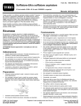
ally disposed in the soil adjacent to the ?rst zone which
with the continuously sampling systems are overcome.
The system is also inherently stable since if it over
waters or underwaters, the next irrigation cycle will
have either a shorter or longer duration, respectively.
The system may also be placed in a bypass mode to
is controlled by the ?rst solenoid.
and a learn button 33. There are also three LED indica
tors: “on” 21, bypass 32, and learned 39.
When switch 31 is turned on, the system will allow
the irrigation system 8 to run without any control from
system 9. In this mode of operation, system 9 will be
allow the user to water even when the inventive con
troller systems have disconnected it from the solenoid
valves.
The initializing software runs a complete memory
check of all locations and, if successful, ?ashes an LED
overridden and no water conservation will occur. This
feature allows the user to manually override system 9
without making any physical changes to the con?gura
tion. This may be important during special watering
on the front panel to alert the user that the unit is func
situations such as a freshly fertilized or seeded lawn.
Moisture sensor 11 is constructed of a series of metal
tioning properly.
It is therefore an object of the present invention to
provide a control system for a water irrigating system
that not only senses the dryness of a soil area, but limits
the amount of water applied to the soil area based upon
conductive spikes that are placed in the soil, where
moisture sensing is desired. As the soil moisture varies,
the resistance measured between opposed conductive
spikes, will vary proportionally. Although this resis
the moisture requirements of the soil and the existing
dampness of the soil so as to conserve the amount of
irrigation water applied to that area.
tance is not a linear relationship with respect to mois
20 ture content, there is a large linear region of resistance.
Sensor 11 is adjusted to operate within that linear por
tion of resistance.
The output of sensor 11 is coupled to the input of
It is another object according to the present invention
to provide a control system for a water irrigating sys
tem that is simple in design, ef?cient and reliable in
operation, and inexpensive in cost.
Other objects and features of the present invention
will become apparent from the following detailed de
scription considered in connection with the accompa
nying drawings, which disclose the embodiments of the
‘
The base unit 9 has two controls: a bypass switch 31
scaling resistance 12. The range and sensitivity of soil
25 moisture sensor 11 can be adjusted to within the linear
range by resistance 12. Moreover, the larger the value
of this resistance, the higher the resistance range of
moisture sensor 11.
There is also provided a free running square wave
invention. It is to be understood that the drawings are to 30 oscillator 13, having its output coupled to an analog to
be used for the purpose of illustration only, and not as a
digital converter 14. Converter 14 derives its set up and
de?nition of the limits of the invention.
sampling timing from oscillator 13. A preferred operat
In the drawings, wherein similar reference characters
denote similar elements throughout the several views:
FIG. 1 is a system diagram showing the irrigation
system of the present invention coupled to an irrigation
controller and a soil sensor;
FIG. 2 is a schematic diagram of the inventive con
ing range of 500 KHz i20% was found to be desirable
for oscillator 13.
Analog-to-digital converter 14 samples the analog
voltage reading from moisture sensor 11, digitizes it,
and outputs an equivalent 8 bit binary word to the ad
dress bus of microprocessor 36. Converter 14 preferably
has a maximum input range of approximately ?ve volts,
trol system of the present invention;
FIGS. 3A, 3B, 3C, 3D and 3E consist of flow charts 40 and a maximum sampling frequency of approximately
showing the operation of the inventive program ac
ten KHZ.
cording to the invention;
There is also provided a gain scaling ampli?er 15 to
FIGS. 4, 5 and 6 are subroutine flow charts for calcu
adjust the maximum threshold of analog-to-digital con
lating zone durations;
verter 14. The threshold output voltage of ampli?er 15
FIG. 7 is a subroutine ?ow chart for wet calculation 45 is set to % of the full scale voltage input of analog to
with a twenty minute timer;
digital converter 14. Ampli?er 15 not only adjusts the
FIG. 8 is a multiplication subroutine chart used in
maximum voltage measurement of converter 14, but
flow charts of FIGS. 3A, 3B and 3C;
establishes the setup size for a single bit. A low pass
FIG. 9 is a one second subroutine flow chart;
?lter16 coupled to the output of ampli?er 15, and hav
FIG. 10 is a validate subroutine;
50 ing its output connected to converter 14, removes high
FIG.
FIG.
FIG.
FIG.
FIG.
11 is an increment counter subroutine;
12 is a decrement subroutine;
13 is an add subroutine;
14 is a divide subroutine; and
15 is a change process control word subroutine. 55
DETAILED DESCRIPTION OF THE
INVENTION
frequency noise and random signals from the input
system coupled to sensor 11. The zero threshold circuit
17 also coupled to converter 14 adjusts the lowest read
ing from the analog to digital converter, or the zero
output.
Triac pump controller 18 is used in conjunction with
optical isolator 19 to gate the 24 VAC power to the
master pump controller (not shown) of irrigation sys
Referring to FIGS. 1 and 2, there is shown the con
tem 8. The master pump controller is only “ON” when
ventional irrigation controller 8 having, for example in 60 there is a zone “ON”. Optical isolator 19 provides elec
this instance, seven zones which are capable of operat
trical isolation between the gate of the triac controller
ing seven solenoids 7 which are located in different
18 and the digital controlled output port or latch 20.
places in the ground to allow water to reach sprinkler
This digital output port latches the control states for
heads as is well known in the prior art. The inventive
sensor 11 (logic “0”=“ON”), optical isolator 19 (logic
control system 9 is coupled to each output of the irriga 65 “0”=“ON”), and conserve indicator LED 39 (logic
tion controller 8 so as to be in series with each of sole
noids 7. A moisture sensor 11 is also coupled to two
terminals of the inventive control system 9 and is gener
“l”=“ON”).
The system also provides a plurality of triac solenoid
controllers 22, each connected to a solenoid 7 to gate
7
4,922,433
the power from the timer irrigation controller 8 to their
respective zone solenoids 7. An optical isolator 23, com
prised of a plurality of optically controlled triacs (one
for each solenoid), provides electrical isolation between
the gates of AC triacs controllers 22, and digital con
trolled latch 24. Output port or latch 24 has the follow
ing blocks latched at this digital port: operation indica
tor LED 21 (logic “0”=“ON”) and optical isolators 23
for each of the solenoid zones (logic “0”=“ON”).
The 24 VAC power lines from irrigation controller 8
enter control system 9 via a terminal strip 6 and are
connected to the anode of their zone triac. These signals
are fed to half wave recti?er 25, resistively scaled by
divider 26, and electrically averaged or smoothed by
8,
ous dynamic variables. A 4.0 MHZ clock 34 provides
the basic system timing for the execution of the system
program, and is coupled to microprocessor 36.
There is also provided a learn pushbutton 33 that
effectively “resets” the system. This momentary push
button controls the interrupt signal to microprocessor
36. Once microprocessor 36 detects the pressing of this
button, the system will abort its current activity and
perform a self check. It then clears the memory (RAM)
or, in other words, erases all characteristic variables it
had used previously including clock durations and
moisture levels. The system will then begin to relearn
the irrigation environment. The user is required to de
press learn pushbutton 33 only when the soil is consid
capacitor 26 to provide the system information on 15 ered to be dry.
.
which zones have been activated. The combination of
Upon a successful completion of this test, the system
these three circuits, comprising the peak detector, 26, 27
will turn on indicator LED 21 via output port 24, to
and 28, generate a signal that has a DC voltage level of
assure the user of system integrity. Absence of this
approximately 2.5 volts when a 24 VAC signal is pres
signal will alert the user that something is not working
ent on the anode of the appropriate triac. It also pro 20 correctly, and that he should consult the user’s manual.
vides system 9 with the facility of ?ltering erroneous
When power is supplied to the unit, power circuit 35
signals caused by electrical noise, spikes, or transients
consisting of an RC network provides a delay of the
that would send the system incorrect information.
execution of the system program until all the electrical
Once the input signals are electrically conditioned by
hardware is at full operating capacity, thus assuring a
peak detector circuits 25-27, they are compared by 25 consistent
and reliable system. Address and control
analog comparator 28 with a reference signal main
lines of MPU 36 are channeled through a decoder 37
tained by threshold circuit 30, to determine if the system
will consider them to be valid or not. If the conditioned
signal is greater than the reference (negative threshold),
the analog comparators will output a digital logic “1” to
buffer 29. If a valid conditioned signal is not present, the
output of comparators 28 is approximately 0.2 V.
Tristate buffer 29 is digitally controlled and will
allow the output signals of comparators 28 (or the indi
cations of valid input signals for zones 1-7) in addition
to the status of the bypass switch 31 to be placed on the
system inputs. Bits 0-7 of the buffer 28 represent zones
1-7 and bit 7 indicates the status of bypass switch 31,
with a logic “1” meaning an “ON” status.
Negative threshold circuits 30 serves as a voltage
and through MSI circuits to provide microprocessor 36
with the facility to address and control the I/O ports of
circuits 14, 20, 24 and 29 and the retrieval of instructions
from the application ROM 38. The application program
. is permanently stored on the ROM 38 as well as the
jump vectors for power up circuit 35 and learn button
33.
The learned indicator LED 39 is turned on by the
system once it has obtained the complete set of irriga
tion environment characteristics. LED 39 provides the
user with the reassurance that the system has shifted
into the conservation phase of operation.
Battery back-up circuit 40 provides the system with
the feature of retaining the irrigation characteristics in
reference, which is applied to the negative inputs to
the event of a power failure by battery backing up the
analog comparators 28 for the conditioned input signals
memory locations where these variables are stored. A
provided by peak detectors 25-27 to provide the system
Ni-Cd battery is trickle charged when the system is
with reliable and consistent data (another form of data
?ltering). An input signal must be greater than one 45 powered on via the 9 V DC power supply of power
supply 24. This charging process requires approxi
forward diode voltage drop of approximately 0.7 v set
mately 14 hours and will be able to supply the memory
by this reference to trigger comparators 28 to signal the
with approximately 6 hours of back-up time. The 9 volt
system that a valid signal for a zone exists.
power from the battery is resistively divided and regu
Bypass switch 31, as indicated earlier, is used to over
ride the system (allowing the timer controller to run
without any intervention from the system). When the
user places switch 31 in the bypass position, a 5 v signal
is applied to buffer 29 thus causing a logic “1” on bit 7
of the digital word retrieved from that port. The system
application program (stored in ROM 38) will recognize
lated to 5 volts by a zener diode.
' A +5 volt power supply regulator 41 supplies all
components on the circuit board with a regulated +5
VDC. The regulator inputs +9 volt DC (unregulated)
from supply 42, scales and regulates it to a for +5 volt
DC output. In addition, there is distributed capacitance
on the supply line for noise and transient ?ltering. Ex
ternal power supply 42 uses the 120 VAC line voltage
from a standard outlet, recti?es and ?lters it to produce
pass state, bypass indicators LED 32 will be turned
a +9 volt DC output. The output is coupled to +5 volt
“ON” to provide the user with a visual reassurance that
system 9 is in the overridden state. When the system is 60 supply 41. The power supply is preferably rated at 120
volt AC and one amp.
in the water conservation phase, bypass LED 32 will be
off.
The learning phase is initialed by depressing learn
At the center of the control system of the invention is
button 33. This phase is responsible for the learning of
microprocessor 36 which executes the application pro
the soil moisture characteristics and the duration set
gram of ROM 38, and provides all the system controls. 65 tings on the existing irrigation system. Learn button 33
MPU 36 has preferably 128 bytes of RAM (Random
is depressed when the soil is considered to be dry, a
the user’s request within one second, and place itself in
the bypass state. When the system is placed in the by
Access Memory) which is utilized by the microproces
condition where one would normally water if it were to
sor to store the irrigation characteristics as well as vari
be done manually.