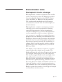
1
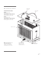
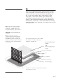
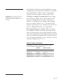
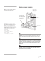
user manual TE 42 and 62 Hoefer TE 42 and 62 ™ transfer electrophoresis unit um TE42-IM/Rev. F0/08-04 Page finder Transfer Electrophoresis Unit function and description . . . . . . . . . . . . . . . . . . . . . 1 Specifications . . . . . . . . . . . . . . . . . . . . . . . . . . . . . . 2 Important information . . . . . . . . . . . . . . . . . . . . . . . . 4 Operating instructions . . . . . . . . . . . . . . . . . . . . . . . . 6 Care and maintenance . . . . . . . . . . . . . . . . . . . . . . . 14 Troubleshooting . . . . . . . . . . . . . . . . . . . . . . . . . . . . 17 Electrotransfer notes . . . . . . . . . . . . . . . . . . . . . . . . 19 Bibliography and references . . . . . . . . . . . . . . . . . . 26 Ordering information . . . . . . . . . . . . . . . . . . . . . . . . 28 • pi Safety warnings and precautions English Important user information Please read this entire manual to fully understand the safe and effective use of this product. The exclamation mark within an equilateral triangle is intended to alert the user to the presence of important operating and maintenance instructions in the literature accompanying the instrument. The lightning symbol within an equilateral triangle is intended to alert the user to the risk of exposure to high voltages. Should you have any comments on this manual, we will be pleased to receive them at: Hoefer, Inc. 953 Indiana Street San Francisco, CA 94107 USA www.hoeferinc.com 1-800-227-4750 Hoefer, Inc. reserves the right to make changes in the specifications without prior notice. Warranty and liability Hoefer, Inc. guarantees that the product delivered has been thoroughly tested to ensure that it meets its published specifications. The warranty included in the conditions of delivery is valid only if the product has been installed and used according to the instructions supplied by Hoefer, Inc. Hoefer, Inc. shall in no event be liable for incidental or consequential damages, including without limitation, lost profits, loss of income, loss of business opportunities, loss of use and other related exposures, however caused, arising from the faulty and incorrect use of the product. • pii Renseignements importants d’utilization Pour une bonne compréhension et une utilisation en sécurité maximale, il convient de lire entièrement ce manuel. Français Dans la documentation qui accompagne l’instrument un point d’exclamation dans un triangle équilatéral a pour but d’attirer l’attention de l’utilisateur sur des instructions importantes de fonctionnement ou de maintenance. Le symbole de l’éclair dans un triangle équilatéral a pour objet d’attirer l’attention de l’utilisateur sur un danger d’exposition à la haute tension. Tous vos commentaires sur ce manuel seront les bienvenus et veuillez les adresser à: Hoefer, Inc. 953 Indiana Street San Francisco, CA 94107 USA www.hoeferinc.com 1-800-227-4750 Hoefer, Inc. se réserve le droit d’effectuer des modifications de ces spécifications sans aucun préavis. Garantie et responsabilité Hoefer, Inc. garantit à l’utilisateur que le produit livré a subi avec succès tous les essais prévus pour s’assurer qu’il est conforme aux spécifications et normes en vigueur. La garantie incluse dans les conditions de livraison n’est valable que si le produit a été installé et utilisé conformément aux instructions fournies par Hoefer, Inc. La société Hoefer, Inc. ne sera en aucun cas responsable de tout dommage causé directement ou indirectement par toute utilisation incorrecte ou non approuvée du produit ou découlant de cette utilisation, y compris toute perte de bénéfice ou de recettes, toute perte de perspectives commerciales, tout empêchement d’utilisation et tout autre risques ayant un rapport avec l’utilisation du produit, mais sans aucune limitation quant à la nature de ces dommages. • piii Wichtige benutzerinformationen Für ein vollständiges Verständnis und eine sichere Handhabung dieses Produktes ist es notwendig, daß der Benutzer dieses Handbuch vollständig durchliest. Deutsch Ein Ausrufezeichen in einem gleichseitigen Dreieck soll den Benutzer auf die Anwesenheit wichtiger Betriebs- und Wartungsanweisungen in der dem Gerät beiliegenden Dokumentation hinweisen. Ein Blitzsymbol in einem gleichseitigen Dreieck soll den Benutzer auf die Gefahr anliegender Hochspannungen hinweisen. Wenn Sie Anmerkungen zu diesem Handbuch haben, dann senden Sie diese bitte an: Hoefer, Inc. 953 Indiana Street San Francisco, CA 94107 USA www.hoeferinc.com 1-800-227-4750 Hoefer, Inc. behält sich das Recht vor, die Spezifikationen ohne vorhergehende Ankündigung zu ändern. Gewährleistung and haftung Hoefer, Inc. garantiert, daß das gelieferte Produkt sorgfältig auf die Einhaltung der veröffentlichten Spezifikationen getestet wurde. Die in den Lieferbedingungen näher erläuterten Gewährleistungsansprüche gelten nur dann, wenn das Produkt gemäß den von Hoefer, Inc. gelieferten Anweisungen installiert und benutzt wurde. Hoefer, Inc. übernimmt keinerlei Haftung für Schäden oder Folgeschäden, einschließlich, aber nicht begrenzt auf Gewinneinbußen, Einkommensverluste, entgangene Geschäftsabschlüsse, Verlust der Gebrauchsfähigkeit oder andere Verluste, die wie auch immer durch eine fehlerhafte oder unsachgemäße Verwendung des Produkts verursacht wurden. • piv Información importante para el usuario Para comprender el producto y utilizarlo con seguridad es necesario leer este manual en su totalidad. Español El signo de admiración en un triángulo equilátero en el manual, advierte al usuario sobre la presencia de instrucciones importantes de operación y mantenimiento del aparato. El símbolo del rayo en un triángulo equilátero alerta al usuario sobre el riesgo de exposición a altas tensiones. Si desearan hacer algún comentario sobre este manual, tengan la amabilidad de remitirlo a: Hoefer, Inc. 953 Indiana Street San Francisco, CA 94107 USA www.hoeferinc.com 1-800-227-4750 Hoefer, Inc. se reserva el derecho a modificar las especificaciones sin previo aviso. Garantía y responsabilidad Hoefer, Inc. garantiza que el producto entregado ha sido probado a fondo para comprobar el cumplimiento de las especificaciones publicadas. La garantía incluida en las condiciones de entrega sólo es válida si el producto se ha instalado y utilizado de acuerdo con las instrucciones entregadas por Hoefer, Inc. Hoefer, Inc. no será responsable, bajo ningún concepto, de daños directos o indirectos, incluyendo sin limitación la pérdida de beneficios, la pérdida de ingresos, la pérdida de oportunidades de negocio, la pérdida de utilización y otras consecuencias relacionadas, cualquiera que sea la causa, que se deban a la utilización defectuosa e incorrecta del producto. • pv Informazioni importanti per l’operatore Per un utilizzo sicuro del prodotto, leggere attentamente l’intero contenuto del presente manuale. Italiano Il punto esclamativo all’interno di un triangolo equilatero indica all’operatore la presenza di importanti istruzioni di funzionamento e manutenzione nella documentazione allegata al prodotto. Il simbolo del fulmine all’interno di un triangolo equilatero indica all’utente la presenza di un rischio di esposizione ad alte tensioni. Si prega di inviare eventuali commenti al presente manuale a: Hoefer, Inc. 953 Indiana Street San Francisco, CA 94107 USA www.hoeferinc.com 1-800-227-4750 Hoefer, Inc. si riserva il diritto di apportare modifiche ai dati tecnici senza preavviso. Garanzia e responsabilitá Hoefer, Inc. garantisce che prima della consegna il prodotto è stato collaudato a fondo per soddisfare i requisiti specificati. La garanzia inclusa nelle condizioni di consegna risulta valida solamente se il prodotto è stato installato ed utilizzato nel rispetto delle istruzioni fornite da Hoefer, Inc. Hoefer, Inc. non potrà essere ritenuta responsabile di incidenti o danni consequenziali, inclusi’ma non limitati’a perdite di profitti, mancato guadagno, perdite di affari, difetti di funzionamento e relative esposizioni, dovuti ad un utilizzo non corretto del prodotto. • pvi Transfer Electrophoresis Unit function and description TE 42 and TE 62 transfer units rapidly transfer proteins, DNA, or RNA from up to four polyacrylamide or agarose gels onto a membrane. Gels and membranes are assembled into a cassette and submerged in a tank filled with transfer buffer. The electrodes in the tank are connected to an external power supply. The TE 62 contains a heat exchanger in the base. Buffer is separated from the coolant by a heat-conducting alumina plate. The TE 42 is not equipped with a buffer cooling system. If cooling is required, an immersible heat exchanger can be ordered separately. Transphor models and features built-in heat exchanger for cooling TE 42 TE 62 compatible with external power supply ✓ ✓ ✓ Unpacking Unwrap all packages carefully and compare contents with the packing list or ordering information, making sure all items arrived. If any part is missing, contact Hoefer, Inc. Inspect all components for damage that may have occurred while the unit was in transit. If any part appears damaged, contact the carrier immediately. Be sure to keep all packing material for damage claims or for repacking should it become necessary to return the unit. • p1 Specifications All tank models: TE 42 and TE 62 This declaration of conformity is only valid for the instrument when it is: Gel size • used in laboratory locations, Max. wattage Max. voltage Max. amperage Max. temperature Buffer required • used as delivered from Hoefer, Inc. except for alterations described in the User Manual, and • connected to other CE labeled instruments or products recommended or approved by Hoefer, Inc. Environmental operating conditions Installation category Pollution degree Dimensions (w × d × h) Product certifications • p2 up to four 15 × 21 cm gels or up to sixteen 7 × 10 cm mini-gels 200 W 100 V [ 2A 45 °C 4–5 liters, depending on the number of cassettes in place Indoor use: 4–40 °C Humidity up to 80% Altitude up to 2000 m II 2 TE 42: 28 × 13 × 30.5 cm (11 × 5.1 × 12 in.) TE 62: 28 × 16.5 × 32 cm (11 × 6.5 × 12.5 in.) EN61010–1, UL3101–1, CSA C22.2 1010.1, CE Fig 1. Transphor main components. TE 42 and TE 62 lid Included but not shown: color-coded leads TE 42: Gel Cassettes (2) Foam sponges, 6 mm thick (2) Foam sponges, 3 mm thick (4) Blotting paper, sheets (25) TE 62: Gel Cassettes (4) Foam sponges, 6 mm thick (4) Foam sponges, 3 mm thick (8) Blotting paper, sheets (25) color-coded electrode panels (2) Tank fill levels Note: An immersible heat exchanger (Code no. TE47) can be ordered separately for the TE 42. TE 62: coolant safety valve and coolant ports (2) cassette hook and holder • p3 Important information • The safety lid must be in place before connecting the power leads to a power supply. English • Turn all power supply controls off and disconnect the power leads before removing the safety lid. • The electric components in the power lid must not become wet. Do not immerse any part of the lid in water. • Rinse only the electrodes (not the banana plugs) with distilled water before use. • Circulate only water or 50/50 water/ethylene glycol through the heat exchanger. Never use anti-freeze mixtures in the heat exchanger. • Do not operate with buffer temperature above 45 °C. All plastic parts are rated for 45 °C continuous duty. • TE 42: For longer runs you can control heating somewhat by chilling the buffer before use, running the unit in a cold room, or both. Overheating will cause irreparable damage to the unit! • TE 62: Circulate coolant through the heat exchanger to minimize heating. Overheating will cause irreparable damage to the unit! Do not connect the heat exchanger to a water tap or any coolant source where the water pressure is unregulated. • When assembling the transfer cassette, use only the required amount of gel support materials (sponges and blotting paper) to prevent overstuffing the cassette. Excess materials may result in cassette damage. • Never expose any part of the instrument to alcohols or organic solvents.* Alcohols or organic solvents will cause irreparable damage to the unit! • If this equipment is used in a manner not specified by the manufacturer, the protection provided by the equipment may be impaired. • Only accessories and parts approved or supplied by Hoefer, Inc. may be used for operating, maintaining, and servicing this product. *Use of ≤20% methanol (methyl alcohol) in transfer buffers is the only exception. • p4 Informations importantes • Le couvercle de sécurité doit être en place avant de brancher les prises au générateur. Français • Eteindre le générateur et débrancher les prises avant d’enlever le couvercle de sécurité. • Les components électriques du couvercle ne doivent pas être mouillés. N’immerser aucun des components du couvercle dans l’eau. • Rinser seulement les électrodes (pas les “bananaplugs”) avec de l’eau distillée juste avant l’utilisation. • Faire circuler seulement de l’eau ou 50/50 d’eau et d’éthylène glycol dans l’échangeur vertical à cirulation d’eau. Ne jamais utiliser d’anti-gel ou tout autre solvant organique avec cet instrument. • Ne pas utiliser avec un tampon à une température au dessus de 45 °C. Toutes les piéces en plastique sont prévues pour résister à une température constante de 45 °C. • TE 42: Pour des coulages plus long, on peut aussi contrôler la température en refroidissant le tampon avant l’utilisation et/ou en utilisant l’instrument dans une chambre froide. Un surchauffement peut causer des dommages irréparables à l’instrument. • TE 62: Faire circuler l’eau dans l’échangeur vertical pour minimiser l’échauffement afin d’éviter des dommages irréparables à l’instrument. Ne pas connecter l’échangeur vertical à circulation d’eau à un robinet ou quelque source de refroidissement dont la pression n’est pas régulière. • Utiliser uniquement la quantité prescrite d’éponges et de papier filtre afin que la cassette ne soit pas trop pleine. Trop de materiels peut endommager la cassette. • Ne jamais exposer l'appareil à des alcools et des solvents organiques.* Les alcools et les solvents organiques causent des dommages irréparables à l'appareil. • Si l’instrument n’est pas utilisé en conformité avec les recommandations du fabriquant, les protections de sécurité qui équipent cet appareil peuvent être rendues inéfficaces. • Seulement les accessoires et piéces detachées approuvés ou fournis par Hoefer, Inc. sont recommandés pour l’utilisation, l’entretien et réparation de cet appareil. *L'utilisation de méthanol à une concentration finale de 20% dans les tampons de transfert constitue la seule exception. • p5 Operating instructions Perform the transfer as soon as possible after electrophoresis to minimize band sample diffusion. Each step is described below. Prepare the buffer Note: Refer to the Electrotransfer Notes section for a discussion of membranes and buffers. Prepare a minimum of 5 liters of the appropriate transfer buffer. Chill before use if possible. Prepare the unit 1 Rinse the transfer tank and cassettes with distilled water. 2 Active cooling is optional but strongly recommended. If no active cooling will be used, go to step 3. Note: Connect the heat exchanger to a circulator bath such as the MultiTemp™ III. Circulate only water or 50/50 water/ethylene glycol to prevent damage to the unit. The circulator pump must not generate a pressure greater than 0.7 bar (10 psi) above atmospheric pressure. Set the temperature to 10 °C or higher if circulating only water. If using 50/50 ethylene glycol/water, the temperature can be set lower. Start the circulator bath at the same time as the transfer. • p6 Note: The relief valve opens if the pressure in the heat exchanger exceeds 0.7 bar (10 psi) above atmospheric pressure. Note: For quick and easy connections, install Quick-disconnect fittings with valves. Note: Even if no cooling is required for your system, the buffer should be circulated with a stirrer to avoid buffer depletion at the electrodes. TE 42 Lower the heat exchanger (ordered separately, or use the heat exchanger supplied with the Hoefer SE 600 Gel Electrophoresis Unit if you have one) into the lower chamber, fitting the ports into the notches in the rim. Prepare two lengths of 10–12 mm i.d. (3/8– 1/2”) vinyl or silicone tubing for the cooling circuit and skip to “Attach tubing” below. TE 62 First attach tubing to the red pressure relief valve between the water inlet and outlet ports and insert the free end into the bath or other container or drain to catch any pressure relief overflow. Prepare two lengths of 9 mm (3/8”) vinyl or silicone tubing and see “Attach tubing” below for instructions on fitting it to the ports of the heat exchanger in the base of the unit. Attach tubing Slide hose clamps (4 total) onto each end of two lengths of tubing. Attach one end of each length of tubing to a heat exchanger port. Attach the free ends of each length of tubing to the circulator bath ports; one to the inlet and the other to the outlet. Secure the connections with the hose clamps. 3 Place (do not drop) a magnetic stirring bar in the buffer tank. (Dropping objects onto the alumina plate in the TE 62 may cause the plate to crack.) Set the unit onto a magnetic stirrer. Fill transfer buffer to the “Start fill level” line. (This requires approximately 3.8 liters.) Set the stirrer to low-medium, which creates buffer circulation without forcing buffer through assembled cassettes. • p7 Assemble the transfer cassette Note: Always wear gloves when handling membranes to avoid getting fingerprints on them. Important! Take great care in removing all air bubbles at each step because the presence of air bubbles, especially between the membrane and gel, blocks transfer. 1 Pre-wet nitrocellulose or nylon membranes with distilled water. Pre-wet PVDF or other hydrophobic membranes in methanol. Then soak all membrane types in transfer buffer for 2–5 minutes. 2 Open the cassette by releasing both latch tabs along the edge opposite the hinges. Place the opened cassette into a tray filled with at least 3 cm of transfer buffer. 3 Assemble the transfer stack so that molecules will migrate toward the membrane. For negatively charged macromolecules (such as nucleic acids and most proteins), build the stack on the grey half of the cassette (and then later position the assembled cassette in the tank so that this side faces the grey anode (+) panel, which connects to the red lead): Place one 3 mm-thick sponge on the opened submerged cassette and press gently until all air is expelled. Place one sheet of blotting paper on the sponge, and then place the membrane on the blotting paper. Place the gel—which contains a sample that has been electrophoretically separated and equilibrated (if required) with transfer buffer—on the membrane. Gently roll a glass pipet or test tube over the gel to expel trapped air between the membrane and gel. Cover the gel with a sheet of blotting paper and then place a sponge of the proper thickness (see diagram on next page), again pressing gently to expel trapped air. • p8 4 Close the cassette and press lightly to lock the tabs. The assembled cassette should hold the gel in firm contact with the membrane without squeezing the gel. If the stack seems loose, add sheets of blotting paper; if the stack seems tight, replace the top sponge (above the gel) with a sheet of blotting paper. If you remove the bottom sponge (below the membrane), substitute at least two sheets of blotting paper to create space between the membrane and the cassette panel. Fig 2. Transfer stack assembly. The stack is oriented so that negatively charged molecules migrate toward the grey anode, +. Important! Do not overstuff the cassette. Note: Try to place the gel correctly the first time because proteins may begin to transfer immediately; once transfer has begun, moving the gel will distort results or cause “shadow bands” on the blot. The cassette panels are color coded: black (top) = cathode side grey (bottom) = anode side one 3 mm sponge for gels >1.5 mm —OR— one 6 mm sponge for gels ≤1.5 mm. blotting paper gel membrane blotting paper one 3 mm sponge Assemble the cassette in a tray containing transfer buffer about 3 cm deep. • p9 Install the cassette(s) 1 The tank holds up to four cassettes; if transferring only one or two gels, use the cassette positions nearest the center. (The submersible heat exchanger, if used in the TE 42, fills the two center slots, so only two cassettes can be placed in the outside slots.) The cassettes must be oriented so that the hinges face up and so that the black side of each cassette faces the black cathode panel. Work quickly when moving the assembled cassette(s) to the tank to avoid draining the sponges: Place the tray holding the cassette(s) near the tank, lift out one cassette at a time, and slide it into a set of vertical slots. Do not discard the buffer in the tray. 2 Once in place, tap each cassette lightly until most air bubbles are dislodged. (A few small bubbles in the sponges are unlikely to interfere with the transfer.) 3 Inspect the buffer level. Add or remove buffer as required so that the level falls between the minimum and maximum buffer level lines. (Buffer above the maximum buffer level line may cause corrosion of the electrical contacts.) Transfer Take care in orienting all system components so that the electric field applied causes all species to migrate toward the membrane. The migration direction depends on both the characteristics of the sample and the pH of the transfer buffer. If the species of interest is negatively charged in the transfer buffer and the stack is assembled so that the membrane is nearest the grey side of the cassette, then this side faces the anode (+). Most proteins migrate toward the anode in • p10 the Towbin Tris/glycine/methanol buffer system (independent of the presence of SDS), and under most conditions nucleic acids are negatively charged and also migrate toward the anode. Important! Never allow the buffer temperature to exceed 45 °C. Excessive heat will cause the unit to warp. Cooling is strongly recommended. Any setting that results in higher than 5 W of power will generate enough heat to require active heat control. A refrigerated circulator bath should be set to cool to about 10 °C. (If using 50/50 ethylene glycol/water, the temperature can be set lower.) Chill buffer before use if possible. Recommended power settings. Most transfers are complete within one hour, but larger molecules or thicker gels may require longer transfer times; the optimum transfer time for each system must be determined empirically. Transfers left to run overnight should be set to a constant current setting no higher than 0.1 A. Typical transfer parameters Parameters for your sample and buffer system must be determined empirically. protein nucleic acids Buffer Towbin 1X TBE or 1X TAE Current (A) 0.8–1.0 0.9–1.0 Voltage (V) 70–80 50 Transfer time ~1 hour ~1 hour Coolant temp. 10 °C 10 °C or less • p11 TE 42 and TE 62 1 Install the safety lid The cassettes and electrode panels are color coded to match the leads in the lid: Orient the lid so that the grey half of the cassettes and the grey anode panel face the anode (+), or red lead, and the black half of the cassettes and the black cathode panel face the cathode (–), or black lead. 2 Note: The two red caps on the lid accommodate the banana plugs on the SE 600 model immersible heat exchanger (irrespective of the orientation). Use only an approved power supply such as the Hoefer PS 2A200. Make sure the power supply is off and all controls are set to zero. Plug the red lead into the red output jack and the black lead into the black output jack. In most systems, the red lead is the anode (+), and the black lead is the cathode (–). 3 Set the power supply Constant current mode is recommended. If constant voltage mode is selected, carefully monitor the current (increased current increases Joule heating). If the current exceeds 1 A, decrease the voltage. If available, set the power supply timer for no more than two hours. • p12 After the transfer is complete 1 Note: It is a good idea to stain the gel to determine the completeness of the transfer. Turn the voltage and current settings to zero and turn off the power supply. Disconnect the leads from the power supply jacks. 2 Lift off the lid. Use the plastic hook (stored in the holder at the side of the unit) to lift up a cassette just far enough to be able to grab it and place it into a tray. 3 Open each cassette carefully and remove the gels and membranes. Label each membrane and indicate the sample side. Lift membrane(s) with blunt forceps and air dry, or follow the instructions of your protocol. 4 Discard the blotting paper, but reuse the sponges. 5 Note: Do not store used buffer in the transfer tank. Chill buffer to 10 °C before reuse. Rinse the unit immediately after use. (See the Care and maintenance section on the next page.) • p13 Care and maintenance Cleaning • Do not autoclave or heat any part above 45 °C. • Do not expose to alcohols or organic solvents!* • Never use abrasive detergents. • If using radioactive reagents, decontaminate the unit with a cleaning agent such as Contrad 70™ and Decon 90™. Rinse the tank, cassettes, and sponges with distilled water immediately after each use. Allow the unit to air dry completely. Periodically wash with a dilute solution of a mild detergent. When cleaning the unit, leave the electrode panels in place. If they must be switched (not recommended), take great care to not stretch or break the platinum wire: carefully pull the panel forward far enough to clear the retaining lip (<5 mm). With one hand grab the banana plug support (not the banana plug) and with the other hand grab the panel at a point well away from the wire. Lift the panel out. • p14 Mains power module Fig 3. The mains power module is located on the back panel. insert screwdriver in this notch to open the cover. insert the screwdriver blade behind the arrow to pull the cassette completely out. Important! Fuses protect equipment by disconnecting loads too large for the instrument’s circuit design, so it is imperative that fuses are replaced only with fuses of identical rating. The mains power module, located at the back of the power lid, contains two input fuses: mains power switch hinged cover 115 V~ model: T 3A 250 V, 5 × 20 mm 230 V~ model: T 1.6A 250 V, 5 × 20 mm 1 Caution: Turn the mains power supply switch off and detach the power cord before replacing input fuses! 2 Open the fuse compartment by inserting a small flatblade screwdriver into the slot at the top of the power module. Twist the screwdriver 1/8–turn to release the cover, then pull out the hinged compartment, which opens out. 3 Insert the screwdriver above the arrow on one fuse cassette, catch the cassette end, and slowly slide it completely out of the module. • p15 4 Pull the fuse out of its cassette and inspect. If the fuse element is burned or broken, replace the fuse with an identical type. If the fuse appears to be intact, check it with a multi-meter. (A reading of 1 Ω or less indicates the fuse is still usable.) 5 After placing a good fuse into the cassette, slide it into the power module, making sure the arrow on the cassette points to the right (in the same direction as the guide arrows on the inside of the compartment door). 6 Repeat steps 3 to 5 for second cassette. 7 Close the fuse compartment cover and gently press it into the power module until it snaps shut. 8 Plug the power cord into the unit and turn the mains power switch on. • p16 Troubleshooting problem solution Incomplete transfer Blank areas on the membrane Remove all trapped air pockets in the transfer stack assembly: assemble the stack while it is submerged in transfer buffer, gently press on each sponge as it is added to the stack, and roll a glass pipette or test tube over the membrane and gel to eliminate all air bubbles. Reduce the stirring speed to prevent turbulence. Process only one strip or membrane in each tray or cassette to prevent overlapping. Use buffer with a lower ionic strength. Check electrode continuity. During the transfer, a continuous stream of gas is released along the entire length of the electrodes. If bubbles do not form along the entire length of the electrode, replace the electrode. If cassettes are bowed when empty, replace. Overpacking the cassette causes it to bow; see the recommended assembly instructions on page 8. Grid pattern on membrane Add extra sheets of blotting paper to increase the clearance between the cassette panel and the gel. Take care not to overstuff the cassette; the gel should be held firmly and evenly between the sponges, but not so tightly that it is squeezed. Molecules do not migrate out of gel Increase the field strength. Increase transfer period. (Try doubling it.) Do not use staining or fixing agents on the gel before transfer. Use a thinner gel. Reduce the gel acrylamide concentration. Check that the buffer pH is close to the intended pH. Most buffers should not be titrated; make fresh buffer. Use 3.5 mM SDS (0.1%) in the transfer buffer. Avoid including methanol in the transfer buffer or reduce the amount to the absolute minimum. Use reagent-grade chemicals. Increase the length of time Southern blots are depurinated. Increase the net charge on the protein by changing to a transfer buffer with a different pH. Lower pH (<6–7) increases the positive charge on proteins; higher pH (>6–7) increases the negative charge on proteins. • p17 problem solution Diffuse band patterns Transfer immediately after electrophoretic separation. If equilibrating before the transfer, shorten or eliminate the equilibration time or move the gel to the cold room during equilibration. If transfer buffer contains methanol (≥10%), equilibrate the gel in transfer buffer for 30 minutes to allow it to shrink before assembling the stack. Note: Because methanol causes the gel to shrink slightly, large molecules may migrate more slowly. Take care that the gel is held firmly against the membrane and that it does not shift once contact is made. If excess heating occurs during the transfer, lower the temperature of the cooling fluid in the heat exchanger. Check that the preferred binding surface of the membrane (if any) contacts the gel. Inefficient binding to membrane Chemical parameters Fix or crosslink the molecule onto the membrane according to the requirements of the nucleic acid, protein, or membrane type. Prepare protein transfer buffer without SDS. Verify the optimal amount of methanol required for the membrane type and check the buffer solution. Add 10–20% methanol to the transfer buffer to enhance binding to nitrocellulose. Membrane parameters Wear gloves when handling membranes. Store membranes at ambient temperature out of direct sunlight to keep the membranes activated. Use a membrane with a smaller pore size (0.10–0.20 µm) if proteins pass through the membrane, or use a different membrane type. Place a membrane both over and under the gel if you suspect one protein is moving in the opposite direction from the majority of the proteins. Check both membranes for protein(s). Check if too much sample is available for the binding surface area by applying two membranes instead of one. If “blow through” occurs, reduce the sample load. For more troubleshooting hints, refer to Bjerrum, O.J. et al. (1988). • p18 Electrotransfer notes Electrophoretic transfer advantages Electrophoretic transfer of proteins and nucleic acids is much faster than the blotting methods first described by Southern for DNA, Alwine et al. for RNA, or Renart et al. for proteins. The tank transfer method uses high current to reduce the transfer time of most samples to 45–60 minutes. Electrophoretic transfer can improve transfer efficiency over non-electrophoretic blotting, especially for proteins, but no quantitative transfer technique has yet been developed due to the complexity of the reactions. Quantitative recovery is actually not required for most purposes because binding macromolecules to a membrane increases the sensitivity of detection methods such as autoradiography and permits detection of specific proteins by antibodies or affinity labels, and of specific nucleic acids by hybridization with complementary strands of RNA or DNA. The buffer can be chosen to result in a transfer toward either the cathode or the anode. The buffer pH must be such that all species of interest are charged and migrate in the same direction. The ionic strength should not be too high, since this will produce excessive current and heat. For this reason, the high salt conditions used by Southern for capillary blotting of DNA cannot be used. The most widely used buffer systems are those of Towbin et al. for transferring proteins, and of Bittner et al. for transferring nucleic acids. Buffer systems for transfer of each type of sample are listed later in this section. • p19 Factors affecting the transfer Parameters such as sample characteristics, membrane type, gel pore size, and the transfer buffer used all contribute to the transferability of macromolecules, and should be kept in mind when developing a protocol. Very small molecular species, for instance, migrate quickly but often do not bind as well as larger molecules; large molecules bind more efficiently but do not elute from the gel as rapidly. The rate of elution is also affected by the pore size of the gel and the orientation of the molecules. Further, the degree to which molecules bind to the membrane is influenced by membrane characteristics such as pore size and type, and buffer characteristics such as pH, salt type and concentration, and the presence of detergents such as sodium dodecyl sulfate (SDS). Conditions required for efficient elution may not coincide with optimal conditions for binding. To find the optimum conditions for transferring your sample, balance these effects: If the sample elution rate is slow, a longer transfer period may be required. (In our experience, low voltage transfers for longer periods do not offer much improvement.) If sample binding is inadequate, try different buffer conditions. For a comprehensive review, see Gershoni and Palade (1983). If the transfer buffer system is different from the electrophoresis buffer system, the gel should be equilibrated with the transfer buffer before the transfer to ensure swelling or shrinking occurs before the gel contacts the transfer membrane. If this step is skipped, band distortion or loss of resolution could result. • p20 Instrument guidelines Cooling Considerable Joule heat is generated during any transfer because of the high current employed, so active cooling is recommended, especially for transfers requiring more than one hour, protein transfers where biological activity must be retained, or transfer of nucleic acids. (The high conductivity of the phosphate buffer used by Bittner et al. (1980) leads to a relatively rapid temperature rise.) Buffer temperature should not exceed 45 °C because the cassettes and electrode supports may warp. Use a circulator bath set to 10 °C if using water as a coolant. (You can use a lower setting if the coolant is 50/50 ethylene glycol/water.) Never leave the unit unattended for more than one hour under high power conditions (>0.5 A). Power setting If using a power supply that can be set to either constant current or constant voltage mode, we recommend that it be set to operate in constant current mode. Buffer conductivity increases with temperature. During blotting in an uncooled chamber, Joule heating and rising conductivity may result in dangerous overheating if the power supply is set to maintain constant voltage. If a constant voltage power supply must be used, monitor and adjust the voltage to maintain a current at or below 1 A. • p21 Protein transfers Study summaries Gershoni and Palade (1982) investigated factors affecting protein recovery from SDS gels to nitrocellulose or DBM paper. According to their findings, methanol in the Towbin buffer system is necessary to achieve efficient binding to nitrocellulose. Methanol improves binding in part by removing protein-bound SDS. In the absence of methanol, labeled bovine serum albumin (BSA) passes through at least five layers of membranes. Methanol may cause a gel to shrink, however, so the elution rate decreases. By using a cationic membrane (such as nylon), which binds the proteins more efficiently, and omitting methanol from the transfer buffer, Gershoni and Palade obtained a much more quantitative transfer. The disadvantage of cationic membrane is that protein stains also bind well, so that the staining background tends to be very high. Properly quenched, however, this paper can be used for antibody detection or other overlay methods of protein identification. A summary of membrane type and recommended methanol concentration follows: membrane type methanol % Charged nylon 0 Nitrocellulose ≤ 20 PVDF ≤ 15 Some workers have reported to us that a low concentration of SDS (0.1%) improves the transfer of protein from an SDS gel. Burnette (1981) and Symington et al. (1981) investigated the effect of the molecular weight of protein. Gibson (1981) describes a method to increase the extent of transfer of large proteins by limited cleavage with pronase during transfer. • p22 Protein transfer buffers Use a buffer with low ionic strength, such as the two listed below, to prevent overheating. Use the alternate CAPS buffer when Tris cannot be used, as in peptide sequencing. CAPS can improve transfer because of its effect on the charge of the protein (see Matsudaira, 1987). For native proteins, we suggest using the electrophoresis buffer for transfer as well. Use the Towbin buffer to transfer SDS-denatured proteins toward the anode. Towbin buffer (25 mM Tris, 192 mM glycine, 20% v/v methanol, pH 8.3, 6 liters) Tris (FW 121.1) Glycine (FW 75.07) SDSa (FW 288.4) 25 mM 18.2 g 192 mM 86.5 g 0.1% (3.5 mM) 6.0 g Dissolve in 4 liters distilled water. Add methanol as requiredb. Bring to 6 liters with distilled water. Do not adjust the pH, which should be between 8.2 and 8.4. Optional: Chill before use. a Optional: Adding SDS can improve transfer efficiency. b Depending on the membrane type selected, adding methanol can improve the transfer results (see discussion and table above). Because buffers containing methanol may deteriorate if stored for long periods, add methanol as required just prior to transfer. CAPS buffer, 1X (10 mM CAPS, pH 11.0, 5 liters) CAPS (FW 221.3) 10 mM 11.1 g [3-(cyclohexylamino)-1-propanesulfonic acid] Dissolve in 4.5 liters distilled water, adjust to pH 11.0 with conc. NaOH. Adjust volume to 5.0 liters. • p23 Nucleic acid transfers Nucleic acids must normally be transferred in denatured form for most efficient binding. RNA is normally denatured with glyoxal before separation or separated in denaturing gels containing formaldehyde or methyl mercury. However, double stranded DNA is usually denatured in the gel with NaOH. The alkali must be neutralized and the gel equilibrated in transfer buffer before electrotransfer. For both DNA and RNA gels, any SDS must also be removed to assure efficient binding. Bittner et al. (1980) wash gels three times, 20 minutes each, to assure complete removal of denaturants and detergents. See Bittner et al. for a study of the transfer efficiency for DNA of different sizes. The Bittner transfer buffer contains 25 mM sodium phosphate, pH 6.5. Also described is a method for the introduction of nicks by limited nuclease action in order to facilitate transfer of larger DNA fragments. Recommended DNA buffers include the Bittner sodium phosphate buffer (see reference) and TBE. For RNA, TAE is recommended. TBE and TAE stock recipes are listed below. These buffers are most often diluted to 1X, but the concentration can range down to 0.1X. Cooling is strongly recommended for these buffers, especially at higher concentrations. • p24 EDTA solutiona (0.5 M EDTA, pH 8.0, 100 ml) Na2EDTA·2H2O (FW 372.2) 0.5 M 18.6 g Dissolve in 70 ml distilled water. Adjust to pH 8.0 with 10 M NaOH (approx. 5 ml), then add distilled water to 100 ml. DNA transfer buffer, 10X (10X Tris-borate-EDTA (TBE) a, pH ~8.2, 1 liter) Tris (FW 121.1) 900 mM Boric acid (FW 61.83) 900 mM EDTA solution (0.5 M, pH 8.0) 20 mM 109.0 g 55.6 g 40.0 ml Distilled water to 1.0 liter. Do not adjust pH. Dilute to 1X before use to yield 90 mM Tris, 90 mM boric acid, and 2 mM EDTA. This dilution is commonly used, but dilutions down to 0.1X may be used should it be necessary to decrease the amount of current in the system in order to control overheating. RNA transfer buffer, 10X (10X Tris-acetate-EDTA (TAE) b, pH ~8.4, 1 liter) Tris (FW 121.1) Acetic acid, glacial (~17.4 M) EDTA solution (0.5 M, pH 8.0) 400 mM 48.4 g ~200 mM 11.4 ml 10 mM 20.0 ml Distilled water to 1.0 liter. Do not adjust pH. Dilute to 1X before use to yield 40 mM Tris, ~20 mM acetate, and 1 mM EDTA. This dilution is commonly used, but dilutions down to 0.1X may be used should it be necessary to decrease the amount of current in the system in order to control overheating. a Current Protocols in Molecular Biology (1993), A.2.1. b Sambrook, J., and Russell, D.W. (2001) Molecular Cloning: A Laboratory Manual, A1.17. • p25 Bibliography and references Alwine, J.C., Kemp, D.J., and Stark G.R., Method for detection of specific RNAs in agarose gels by transfer to DBM paper and hybridization with DNA probes. Proc. Natl. Acad. Sci. USA. 74, 5350–5354 (1977). Bittner, M., Kupferer, P., and Morris, C.F., Electrophoretic transfer of proteins and nucleic acids from slab gels to diazobenzyloxymethyl cellulose or nitrocellulose sheets. Anal. Biochem. 102, 459–471 (1980). Bjerrum, O.J., Larsen, K., and Heegaard, N., CRC Handbook of Immunoblotting of Proteins Vol. 1, Section 7. CRC Press (1988). Burnette, W.N., Western blotting electrophoretic transfer of proteins from sodium dodecyl sulfatepolyacrylamide gels to unmodified nitrocellulose and radiographic detection with antibody and radioiodinated protein A. Anal. Biochem. 112, 195 (1981). Gallagher, S., Winston, S.E., Fuller, S.A. and Hurrell, J.G.R., Immunoblotting and Immunodetection. In Current Protocols in Molecular Biology. 10.8.1– 10.8.17. Greene Publishing and Wiley-Interscience, NY (1993). Gershoni, J.M., Davis, F.E. and Palade, G.E. Protein blotting in uniform or gradient electric fields. Anal. Biochem. 144, 32–40 (1985). Gershoni, J.M., and Palade, G.E. Electrophoretic transfer of proteins from sodium dodecyl sulfate-polyacrylamide gels to a positively charged membrane filter. Anal. Biochem. 124, 396–405 (1982). Gershoni, J.M., and Palade, G.E. Protein Blotting: Principles and Applications. Anal. Biochem. 131, 1–15 (1983). Gibson, W. Protease-facilitated transfer of high molecular weight proteins during electrotransfer to nitrocellulose. Anal. Biochem. 118, 1 (1981). • p26 Lin, W., and Kasamatsu, H., On the electrotransfer of polypeptides from gels to nitrocellulose membranes. Anal. Biochem. 128, 302–311 (1983). Matsudaira, P. Sequence from Picomole Quantities of Proteins Electroblotted onto Polyvinylidene Difluoride Membranes. J. Biol Chem. 262, 10035 (1987). Ohmsted, J.B., Affinity purification of antibodies from diazotized paper blots of heterogeneous protein samples. J. Biol. Chem. 256, 11955 (1981). Renart, Reiser, J. and Stark, G.R. Transfer of proteins from gels to DBM paper and detection with antisera: a method for studying antibody specificity and structure. Proc. Natl. Acad. Sci. USA 76, 3116 (1979). Sambrook, J., and Russell, D.W. Molecular Cloning: A Laboratory Manual, Cold Spring Harbor Laboratory Press, A1.17 (2001). Southern, E.M. Detection of specific sequences among DNA fragments separated by gel electrophoresis. J. Molec. Biol. 98 (3):503–517 (1975). Stellway, E.J., and Dahlberg, A.E. Electrophoretic transfer of DNA, RNA, and protein onto DBM paper. Nucleic Acids Res. 8, 299 (1980). Symington, J., Green, M., and Brackmann, K., Immunological detection of proteins after electrophoretic transfer from gels to diazo paper: analysis of adenovirus encoded proteins. Proc. Natl. Acad. Sci. USA 78, 177–181 (1981). Towbin, H., Staehelin,T., and Gordon, J., Electrophoretic transfer of proteins from polyacrylamide gels to nitrocellulose sheets: procedure and some applications. Proc. Natl. Acad. Sci. USA. 76, 4350–4354 (1979). • p27 Ordering information product quantity code no. TE 62 Cooled Transfer Electrophoresis Unit. Includes safety lid with power cables, 4 gel cassettes, 8 foam sponges 3-mm thick, 4 foam sponges 6-mm thick, 25 sheets of blotter paper. 1 TE62 TE 42 Transfer Electrophoresis Unit. Includes safety lid with power cables, 2 gel cassettes, 4 foam sponges 3-mm thick, 2 foam sponges 6-mm thick, 25 sheets of blotter paper. 1 TE42 Glass heat exchanger for TE 42 1 TE47 Electrode panel, black 1 TE43BK Electrode panel, grey 1 TE43GY Gel cassette, 2 foam sponges 3-mm thick, 1 foam sponge 6-mm thick. 1 TE44H Lower buffer tank for TE 42 1 TE56 Lower buffer tank with heat exchanger for TE 62 1 TE67 Sponges, Dacron, 6-mm thick. 2 TE45 Sponges, foam, 6-mm thick. 4 TE45F Sponges, foam, 3-mm thick. 4 TE45F-1/8 Lid with cables for TE 42 or TE 62. 1 TE49 High voltage leads with jacks 1 SE6056-HV Quick-fit coupler body, female, to fit 9.5 mm (3/8”) ID tubing. 2 QF3/8 Quick-fit coupler body, male, to fit 9.5 mm (3/8”) ID tubing. 2 QFX3/8 Accessories and replacement parts Blotter paper Blotter paper, sheets, 9 × 10.5 cm 50 TE26 Blotter paper, sheets, 14.5 × 21.5 cm, equiv. to Whatman #1MM. 50 TE46 Companion products Hoefer PS 2A200 Power Supply, 200 V, 2A • p28 1 PS2A200 Contrad 70 and Decon 90 are trademarks of Decon Lab. Printed in the USA Hoefer, Inc. 953 Indiana Street San Francisco, CA 94107 USA www.hoeferinc.com • p30