1
4
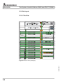
Structure of the R&S TS-PSYS2
3-26
3.4.5
3.4.5.1
3.4.5.2
3.4.5.3
3.4.5.4
3.4.5.5
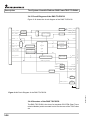
Functional Description of the R&S TS-PSYS2
Control
System Functions
System Clock
Signal Looping
Local Signal Outputs
3-28
3-28
3-28
3-29
3-30
3-30
3.4.6
Driver Software
3-31
3.4.7
Self-Test
3-31
Function Description
3-31
3.6
Permitted Module Configurations
3-32
Commissioning
4-1
4.1
Safety Instructions
4-1
4.2
Setting Up
4-1
4.2.1
Requirements for Repeatable Measurements
4-1
4.2.2
Rack Mounting
4-1
4.2.3
Desktop Setup
4-2
4.2.4
Operating Position
4-3
4.4
4.5
4
3.4.4
3.5
4.3
5
Test System Versatile Platform R&S PowerTSVP TS-PWA3
Installation
4-4
4.3.1
Safety Instructions
4-4
4.3.2
Compatibility
4-4
4.3.3
Module Installation
4-4
4.3.4
Driver Installation
4-5
Connections
4-6
4.4.1
Line Inlet
4-6
4.4.2
Connections at the Rear
4-6
4.4.3
Connections at the Front
4-7
Cabling
4-8
4.5.1
Concept
4-8
4.5.2
Analog bus
4-9
4.5.3
PXI Trigger Bus
4-10
4.5.4
External Cabling
4-10
4.5.5
Opening the Case
4-10
Operation
5-1
5.1
General
5-1
5.2
Self-Test
5-1
9th Issue 09.11
Contents