1
Cycle Analyst V3.0
Unofficial User Guide
Beta Release – B22
teklektik
1.0 Overview.............................................................................................................................................. 2
1.1 Concept........................................................................................................................................... 2
1.2 Features........................................................................................................................................... 2
1.2.1 User Configurable Presets............................................................................................................2
1.2.2 Pedal Assist............................................................................................................................... 2
1.2.3 Auto-Cruise Control....................................................................................................................3
1.2.4 Temperature Sensing..................................................................................................................3
1.2.5 Diagnostic Displays.....................................................................................................................3
1.2.6 Throttle Enhancements................................................................................................................3
1.3 Input Summary................................................................................................................................. 4
2.0 Display Screens and Console Operation.....................................................................................................5
2.1 Basic Button Navigation......................................................................................................................5
2.2 Mode Presets.................................................................................................................................... 5
2.3 Screen Summary...............................................................................................................................5
2.3.1 Setup Screens............................................................................................................................5
2.3.2 Status Screens...........................................................................................................................6
3.0 Basic Installation................................................................................................................................... 8
3.1 Install Hardware................................................................................................................................ 8
3.2 Determine and Save Device-Specific Settings – Important!....................................................................12
3.3 Update CA with Most Recent Firmware................................................................................................12
3.4 Calibrate Current and Voltage Measurements (Make Device-Specific Settings)..........................................12
3.5 Set Up Baseline Configuration............................................................................................................13
3.6 Set Throttle Input/Output Voltages.....................................................................................................14
3.7 Test Throttle and Limit Settings.........................................................................................................16
4.0 Throttle Ramping Adjustments...............................................................................................................17
5.0 Gain Adjustments: Minimizing Surging or Speed Oscillations......................................................................17
5.1 Current and Power Limiting (Current and Power Throttle)......................................................................18
5.2 Speed Limiting (Speed Throttle).........................................................................................................18
6.0 Advanced Features............................................................................................................................... 19
6.1 Closed-Loop Throttle Modes..............................................................................................................19
6.2 Auto-Cruise Control..........................................................................................................................20
6.3 Auxiliary Pot................................................................................................................................... 21
6.4 eBrake........................................................................................................................................... 23
6.5 Pedal Assist.................................................................................................................................... 24
6.6 Temperature Sensor.........................................................................................................................27
6.7 High Voltage Vehicle Support.............................................................................................................28
6.8 Cycle Analyst as a Power Source........................................................................................................29
6.9 Serial Data Port............................................................................................................................... 31
Appendix A. CA V3 Throttle OUT to Controller Connection.................................................................................32
Appendix B. Tuning Speed Control Gain Parameters.........................................................................................33
Appendix C. CA V3 Connector and PCB Images...............................................................................................35
Appendix D. Tips and Tricks.........................................................................................................................36
This is a 'best effort' work intended as a temporary measure until formal documentation is available. Selected text
from the Grin Tech site is quoted in-line with colored background for reference. Please review the authoritative
documentation on that site for more contemporary versions. Also see the Endless-Sphere.com thread
“Cycle Analyst V3 preview and first beta release” from which much of this material has been drawn.
2013-03-14 1200 (B22)
1/39
Unofficial CA V3 User Guide
1.0 Overview
1.1
Concept
The Cycle Analyst V3 measures and displays detailed information about the battery, acts as a general purpose trip
computer, records and calculates statistics on vehicle performance, monitors and displays data from optional input
devices, and limits the motor controller based on the monitored and calculated data. This affords a single integrated
solution to display and control vehicle operation with all control passing to the motor controller via a single throttle
signal. This approach allows any motor controller to be upgraded with advanced features like torque-sensing PAS or
over-temperature power rollback.
In the role as intermediary between controller and accessory devices, the Cycle Analyst also processes the operator
throttle and combines it with other inputs to arrive at a single output throttle signal. This provides an opportunity to
provide options to enhance operator throttle operation. These options can materially improve the driving experience
by smoothing power application and mitigating uneven and quirky throttle response.
1.2
Features
1.2.1 User Configurable Presets
The V3 offers up to three Battery Presets that allow rapid reconfiguration when installing different battery packs.
Battery statistics are associated with each preset so unique historical information is maintained for each individual
pack.
Up to three additional Mode Presets are provided to allow easy selection of suites of preconfigured parameter settings.
These may be used to switch between different power limitations (e.g. legal, off-road), to enable/disable assist
modes, or to customize throttle behavior for different riding situations.
1.2.2 Pedal Assist
The Cycle Analyst supports both PAS cadence sensors and torque-sensing devices such as the Thun bottom bracket.
These can be operated in a variety of modes that include simple PAS-only, combined throttle-PAS, and special 'no
throttle without pedaling' modes to comply with various pedalec legal requirements.
2013-03-14 1200 (B22)
2/39
Unofficial CA V3 User Guide
1.2.3 Auto-Cruise Control
The Cycle Analyst can be configured to provide a firmware-only auto-cruise control capability that holds the present
throttle setting if the throttle remains unchanged for a period of time. The delay to trigger the cruise control as well
as the amount of throttle motion that will be ignored by the trigger logic are both configurable. Auto-cruise releases
on ebrake input or throttle application.
1.2.4 Temperature Sensing
The Cycle Analyst provides a temperature sensor input that supports either NTC (Negative Temperature Coefficient)
thermistors or linear devices like the LM335. In addition to displaying the temperature, the V3 moderates heat
generation by throttling back the controller as temperature rises through a configurable limit range.
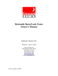
1.2.5 Diagnostic Displays
The Cycle Analyst has several displays designed to simplify setup and
problem resolution. The status screen to the right shows throttle input and
output voltages as well as an array of flags that indicate which of the
limiting parameters are presently in play and restricting controller power.
Other Setup screens display real time data values of related input
parameters. This allows the signals from throttle, 3-position switch, PAS,
and temperature devices to be inspected without external test equipment.
The display to the right shows the voltage from a custom external PAS
assist level adjustment knob.
1.2.6 Throttle Enhancements
The V3 provides three means to enhance throttle operation:
•
throttle/controller voltage matching,
•
throttle ramping, and
•
alternative feedback-based throttle modes.
1.
Throttle dead zones and motor creep occur when the throttle output voltage range is not identical to the
throttle input range of the motor controller. The Cycle Analyst provides configuration options to match the
requirements of these two devices without additional test equipment.
2.
Configurable throttle ramping provides a means to ease the application and removal of controller power. This
is of particular value to vehicles with powerful motors or with motors/drivetrains containing gears, clutches,
chains, etc. Ramping is universally applied to the generated Throttle Out signal and so affects all operation,
not just the operator throttle. This feature can make the bike more controllable and can safeguard drivetrain
components.
3.
Perhaps the most valuable throttle feature is the ability to employ one of three additional closed-loop feedback
modes: Current, Power, or Speed Throttle. In these modes the operator throttle is not used for direct control
but rather provides a 0-100% target level of the configured current, power, or speed limit for the Cycle
Analyst to achieve. The V3 runs the controller independently, monitoring speed, shunt, and/or battery voltage
and computing the necessary controller throttle voltage to achieve the operator target. This fly-by-wire
approach masks quirky controller/motor behavior by making difficult controller throttle adjustment the
responsibility of the CA, not the operator.
2013-03-14 1200 (B22)
3/39
Unofficial CA V3 User Guide
1.3
Input Summary
The V3 is housed in the same Large Screen console as the V2 but the offers expanded features with a new circuit
board, more powerful processor, and increased memory.
The V3 provides these inputs:
Communication: There is an Rx / Tx and Gnd for hooking up a TTL->USB converter. This can be used for
data logging, bootloading new firmware, or configuring setup parameters from a computer rather than by
pushing buttons through the Setup menu.
Temperature: This input can be either a 10K NTC thermistor, or a linear temperature sensing IC like the
LMx35 series.
Aux Pot Input: This is a general purpose 0-5V input that can be used to support custom user inputs such as
a PAS level knob, speed knob, 3 position switch, or 'preset switch' to externally select CA mode presets.
Ebrake Cutoff: Instead of running an ebrake brake signal wire back to the controller, it can go to the CA
which in turn inhibits the throttle signal.
RPM / Dir / Trq: The pedal assist connector is laid out primarily with the THUN torque sensing bottom
brackets in mind, but also supports regular PAS cadence sensors and other torque sensors such as those from
FAG from Germany or GreenTrans from Taiwan.
External VPack: This input can be connected to a custom resistive divider to allow monitoring voltages
different than the Cycle Analyst supply voltage. This gives the option to monitor battery packs up to 500v
while the CA itself is powered from a separate low voltage source such as a 12v DC/DC converter.
2013-03-14 1200 (B22)
4/39
Unofficial CA V3 User Guide
2.0
2.1
2.2
Display Screens and Console Operation
Basic Button Navigation
1.
Press right/left buttons to navigate Status or Setup Screens
2.
Press/hold right button to reset trip statistics
3.
Press/hold left button to enter Setup
Mode Presets
Mode and battery presets are configured in Setup and may be selected in Setup or at any time from the main status
screens using both buttons in 'hot swap' mode:
1.
Select Mode Presets by holding the left button then tapping the right to sequence though presets.
2.
Select Battery Presets by holding the right button then tapping the left to sequence though presets.
Mode presets may also be selected by means of a custom external 'preset switch' (see ' 6.3 Auxiliary Pot'). The CA
can be configured to power up with the either a fixed default or the mode preset in effect when last powered down.
Historical battery statistics (see 'Status Screens' below) are accumulated independently for each battery preset. By
assigning a separate battery preset to each battery pack, unique historical data will be available for individual packs.
2.3
Screen Summary
Although the images in this section were accurate at the time of publishing, they may become dated because of
firmware updates and are presented only to illustrate general content, style, and techniques.
2.3.1 Setup Screens
The setup screens are divided into sections, each prefaced with a section preview screen. The preview screens
typically show an abbreviated summary of important parameters within the section.
2013-03-14 1200 (B22)
5/39
Unofficial CA V3 User Guide
Some preview screens display live data which can be identified by rapid blinking or flickering of the displayed value.
These screens are generally self-explanatory, but certain display features warrant special mention.
1.
The 'SETUP THROT OUT' screen (#4 above) shows the configured min/max output voltages followed by a
small sloping line. The steepness of the slope reflects the relative rate configured for ThrO->UpRamp.
2.
The Speedometer and PAS preview screens use animated glyphs to
indicate the live hi/lo values of digital inputs. The screen to the
right shows a speedometer with 3 poles (spoke magnets). The
small arrow adjacent to the tiny raised “P” points up/down
according to the hi/lo state of the SP input (wheel pickup). Proper
pickup operation can be easily verified by observing the arrow
while rotating the wheel. The PAS Preview Screen has similar
arrows indicating the hi/lo states of the RPM and Dir inputs.
Press-hold the right button on any preview screen to enter the section and
edit individual parameters. Each parameter is configured on an individual
screen. Advance to the desired parameter screen and press-hold the right
button to edit.
Note: Certain Setup parameters have global significance and are not part of any preset (e.g. tire circumference) while
others are preset-specific (e.g. number of battery cells) and may be set differently in each preset. To determine if a
parameter is global or preset-specific, see the most recent configuration summary file listed in this post. Individual
Setup parameters are described in detail on the Grin Tech V3 web page.
2.3.2 Status Screens
There are eleven Status screens which display information grouped by function. Some information (e.g. speed, Amps)
is displayed on more than one screen to give the operator a more comprehensive view without changing screens.
Most screens are self-explanatory, but some deserve a bit of clarification
1.
In PAS screens (#3 and #5 above) 'HW' refers to generated 'Human Watts' measured by the CA.
2.
'Rbatt' on the Battery screen (#10 above) refers to the calculated battery resistance which will normally vary
with temperature.
2013-03-14 1200 (B22)
6/39
Unofficial CA V3 User Guide
3.
The Diagnostic Screen contains a character string of Limit Flags. A
capital letter indicates that the limit is asserted and may be
moderating power to some degree. More than one limit flag may be
in play at once. When the throttle is configured for one of the
closed-loop throttle modes, the associated limit flag will appear
asserted almost continuously, even at standstill, since in these
modes the throttle operates by limiting Throttle OUT to some
fraction of a particular limit parameter (e.g. MaxCurrent = 100A).
4.
The Main Status screen appears simple but displays the following
status information in addition to the numeric values:
1.
the Battery Gas Gauge indicates battery SOC from Full
to Empty,
2.
the Operator Throttle bar graph shows 0-100% of the
configured Throttle IN range (far left on 2 nd line),
3.
the Human Power bar graph shows measured torque
from the torque sensor (adjacent to throttle graph),
4.
an animated ebrake lever glyph replaces the throttle bar
graph when ebrakes are applied,
5.
the leftmost numeric value of the 2nd line may be
configured to display either Watts or Amps,
6.
the rightmost numeric value on the 2 nd line alternates display of distance, Amp hours, and if the sensor is
enabled, temperature in degrees C,
7.
exceeding a limit causes the units to flash: 'V' flashes if below LVC, 'kph/mph' flashes if over the
configured speed limit,
8.
the speed digits flash if the present speed is less than the configured Start Speed, and
9.
when auto-cruise is triggered a second blinking 'ghost' slider appears on the throttle bar graph at the
selected 'cruise throttle' position. The normal throttle slider is unchanged and moves normally.
Appearance of the blinking slider gives a visual cue that auto-cruise is engaged and it is no longer
necessary to hold the operator throttle in place.
Depending on the installed suite of accessories, certain status screens will
be of negligible or limited value. The Preferences Setup section provides
means to hide any of the eleven screens so only information of interest is
accessible. The CA utilizes two such configurations to differently customize
displayable screens when at rest and when underway. This allows use of an
abbreviated screen set for rapid display navigation while in motion.
The strings of 1's and 0's are configured to enable/disable display of status
screens in the order navigated by pressing the right button. In the sample
screens to the right, all screens are visible at rest while all but three are
hidden when underway – only screens 1, 4, and 8 are accessible.
2013-03-14 1200 (B22)
7/39
Unofficial CA V3 User Guide
3.0 Basic Installation
3.1
Install Hardware
1.
If upgrading from a CA V2, record the value of the shunt on the existing system prior to removing the old CA.
2.
Familiarize yourself with V3 components by briefly reviewing 'Appendix C. CA V3 Connector and PCB Images'.
3.
Mount the CA Console and Optional Wheel Pickup
Grin Tech CA v2.23 User Manual:
“The Cycle Analyst display box comes with a mounting bracket for installation on the handlebar of your
bicycle. This bracket can rotate in two axis to adjust the display position. Use rubber shims as required around
the tube if the clamp diameter is too large for your bar.”
In the case of the CA-SA, CA-DPS, and CA-HC models, there is also a speedometer pickup cable and spoke
magnet. The pickup attaches to the fork with two cable ties, and must be mounted to pass within 2mm of the
magnet for the speed readings to register. For systems like scooters or motorcycles that don’t have spoked
rims, a standard magnet can be attached with epoxy to a suitable location on the wheel.”
Multiple spoke magnets may be installed to improve low speed responsiveness when using closed-loop 'speed
throttle' (see ' 6.1 Closed-Loop Throttle Modes'). They need not be placed exactly evenly.
4.
Connect the CA Console to Controller, Shunt, and Power
This step will vary according to the particular model of CA, controller, and shunt.
1.
Installation with CA-DP(S) and CA-Compatible Controller
Grin Tech CA v2.23 User Manual:
“With the Direct Plug models, simply plug the 6-pin connector of the CA into the matching 6-pin
connector on the motor controller. Because there are large voltages present through this connector, it is a
good idea to protect the pins with dielectric grease, particularly if it will be exposed to wet conditions.”
2.
Installation with CA-DP(S) and SA Molded Shunt Module
Grin Tech CA V2.23 User Manual:
“With the Stand Alone version, wire the molded shunt in between your battery and the motor controller.
This is most conveniently done by attaching connectors on the shunt leads which match your battery
connectors. If you have a switch in the system, it is best to wire the shunt after the switch so that the
Cycle Analyst powers down.”
2013-03-14 1200 (B22)
8/39
Unofficial CA V3 User Guide
Connect the shunt and console CA-DP connectors as done with the controller connector in Step 1 above.
The optional Cycle Analyst external plug-in shunt comes with a short cable that breaks out the throttle,
speedometer, and ground connections from the DP connector. These breakout connections are addressed
in following steps.
3.
Installation with CA-DP(S) and High Current External Shunt
Grin Tech CA V2.23 User Manual:
The High Current model attaches to a 3rd party shunt resistor and the positive battery lead. The shunt
must be connected to the ground side of the battery; connection of the shunt to V+ can damage the
circuitry.
Wire a male JST-6 connector as shown above.
The CA Gnd (CA-DP(2)) may be attached to either +Shunt or -Shunt, but the rule is to connect it such
that CA Gnd is identical to controller Gnd to improve the quality of ground-relative signals (throttle).
For external shunts, this means CA-Gnd should be tied to +Shunt. The optional CA-SA external molded
shunt follows this same policy. Controllers with an internal shunt normally tie controller Gnd to -Shunt
and so likewise tie CA Gnd of the controller CA-DP connector to -Shunt.
Connect the shunt and console CA-DP connectors as done with the controller connector in Step 1 above.
2013-03-14 1200 (B22)
9/39
Unofficial CA V3 User Guide
4.
Installation with CA-DP(S) and RC ESC (Electronic Speed Controller)
Wire the ESC using the preceding technique for an external high current shunt. If the current is 50A or
less, the CA-SA molded shunt module may be used instead, in which case wire the ESC as in the
preceding CA-SA section.
In either case, also wire CA-DP(6) (ThrO) to the ESC Servo Pulse Input.
This connection is available on the CA-SA molded shunt breakout cable as the green wire.
If the ESC has no on-board BEC (Battery Eliminator Circuit), then the yellow CA-DP(5) connection for SP
input can be re-purposed to utilize the CA 5v supply as the BEC.
• On the controller end, tie CA-DP(5) to the ESC BEC input.
This connection is available on the CA-SA molded shunt breakout cable as the yellow wire.
• On the CA end, tie the yellow CA-DP wire to either the Throttle or AUX Pot 5v PCB pads. If working
with a CA-DP instead of CA-DPS, it will be necessary to first unsolder the yellow wire from the CA
PCB SP pad under the brown square polyfuse.
CA-DPS Wiring to Supply 5v to RC ESC without BEC
Note: The older V2 DP cable and speedometer pickup are essentially identical to those of the V3 and have the
same cable color coding. The V2 shunt is a perfectly acceptable external shunt for V3 operation and the four
wires of the V2 shunt have the same color coding as the V3 DP cable/molded shunt combination. This allows
reuse of existing V2 wiring if desired. The new V3 molded shunt module has a breakout cable to make throttle
wiring a bit easier, but this can be achieved by other means.
After this step the CA will have power and shunt connections but the throttle will require additional attention.
5. Hook up Throttle
Important: See 'Appendix D. Tips and Tricks' if using a resistive (Magura) throttle.
If using an RC ESC, the throttle was already connected in the previous section. Skip to Step 6. - 'Customize
Speedometer Installation (Optional)'.
Otherwise, there are two choices - relocate the operator throttle connections to the CA or use the legacy
'Throttle Override' mode with the throttle connected to the controller. Legacy mode is an easy 'first attempt'
just to get the CA running without wiring changes if you are replacing a V2 with a V3, but it precludes access
to new V3 throttle-related features.
2013-03-14 1200 (B22)
10/39
Unofficial CA V3 User Guide
1.
EITHER - New v3 Operation (CA Provides Throttle – Preferred)
To take advantage of the new throttle features, the throttle must be controlled by the CA.
1.
Connect the throttle to the CA using the provided connector.
2.
Hook the CA Throttle OUT connection to the controller using one of the following techniques:
1.
Use one of the approaches described in 'Appendix A. '
2.
As of Dec 2012, the optional CA-SA external plug-in shunt comes with a short cable that breaks
out the throttle, speedometer, and ground connections from the DP connector. Attach the green
throttle wire to a mating connector matching your controller throttle-in connector.
Note: If the controller does not respond even though the V3 presents a proper throttle control voltage as
measured at the controller throttle input pin, then the controller may employ a 'missing throttle' safety
circuit. Certain controllers (e.g. Yiyun YK43) block operation if the throttle is unplugged as determined by
the absence of current in the throttle connector (+/-) leads. If this symptom presents, simulate the
presence of a throttle by adding a 1K resistor across the controller throttle (+/-) leads. To preserve the
'disconnect' safety feature, this is best done across pins of the mating throttle connector carrying the
green CA ThO wire. This resistor is harmless although unnecessary for controllers lacking a safety circuit.
2.
OR - Legacy Operation (CA Limits Operator Throttle - Older v2.x style Operation)
Connect the throttle to the controller in the older V2 fashion (e.g. plug in the CA-DP cable).
6.
Customize Speedometer Installation (Optional)
The CA V3 comes in two forms: CA3-DP using speedometer signals from the controller (DD) and CA3-DPS
with wheel pickup wired into the console (DD or gear motors).
2013-03-14 1200 (B22)
11/39
Unofficial CA V3 User Guide
If you have a CA-DPS (or older beta release version) and wish to eliminate the wheel pickup for DD
installations, unsolder the pickup cable from the CA PCB and solder the loose yellow wire from pin 5 of the
controller CA-DP connector to the Sp pad of the PCB (under the square brown polyfuse). Be sure to
reconfigure the speedometer pole count appropriately in the steps below.
The optional CA-SA external molded plug-in shunt comes with a short breakout cable. This may be used in
custom installations with a wheel pickup (yellow, black wires) or to route a hall signal (yellow wire) from the
controller or controller DP connector.
3.2
Determine and Save Device-Specific Settings – Important!
1.
Enter Setup and record the value of Cal->VScale which calibrates voltage measurements.
This is specific to your CA and is set by Grin Tech during production.
2.
Determine and save the value to used for Cal->RShunt which calibrates current measurements.
This is one of:
• 1 mOhm if using a new V2 or V3 external plug-in style shunt
• the shunt value of your specific controller
• the specific shunt value of your old V2 wired-in external shunt (value was saved above)
• the value of some other custom or high power external shunt
3.3
Update CA with Most Recent Firmware
1.
Download the most recent firmware from the Grin Tech Site if the CA splash screen does not show the
most recent version.
2.
Flash the new firmware as described on the Grin Tech Site. At this early stage of product maturity, it's
best to order a programming cable (CA3-USB) with your CA. See ' 6.9 Serial Data Port' for details.
There are two ways to enter the CA bootloader mode when
using the uploader application:
• If 'Update Firmware' is pressed with the CA powered
down, the uploader will display a message:
“Please power cycle the device...”.
• If 'Update Firmware' is pressed with the CA running
normally, the CA will detect the uploader, display the
screen to the right, and enter bootloader mode without the need for a manual power cycle.
As a matter of policy, using the most recently available uploader will ensure full feature functionality and
will eliminate firmware installation difficulties.
Note: The settings in the Calibration section of Setup can be preserved during re-flash by using the 'NoCal'
firmware hex file version. However, flashing erases all 'non-Calibration' settings. When performing subsequent
firmware updates, first record all non-Calibration settings so that you may restore them when the re-flash is
complete. The configuration summaries located in this post each contain a printable form to assist you.
3.4
1.
Calibrate Current and Voltage Measurements (Make Device-Specific Settings)
Configure Current Range, Voltage Scaling, and Shunt
Important: The V3 can operate in either of two modes to support vehicles drawing a maximum of
99.9 Amps (Cal->Range=Lo) or 999 Amps (Cal->Range=Hi).
Cal->Range differs from other Setup parameters and should not to be changed once the unit is configured.
Altering Cal->Range can have unforeseen effects on previously configured settings and associated Setup
entry screens. If configuration entry difficulties arise due to such alterations, re-flashing may be necessary.
2013-03-14 1200 (B22)
12/39
Unofficial CA V3 User Guide
1.
2.
If Maximum Amps < 100A …
1.
Set Cal->Range = Lo (W)
2.
Set Cal->VScale and Cal->RShunt as determined above
3.
The flashed PLim->AGain and PLim->WGain values provide suitable defaults.
(e.g. for v3B22 (AGain,WGain) = (150, 050) )
If Maximum Amps >= 100A ...
1.
Set Cal->Range=Hi (kW)
2.
Set Cal->VScale and Cal->RShunt as determined above
3.
Scale up the default values of PLim->AGain and PLim->WGain by 10x or set to 999 if the scaled
value is 1000 or greater (e.g. for v3B22 revise (AGain,WGain) = (999, 500) )
Important: The value of Cal->Range is not preserved when flashing and is instead reset to Lo. If you
are using the Hi setting and flash, always reset Cal->Range = Hi as the first configuration item
immediately after flash. This will ensure that other preserved calibration values are properly interpreted
and that entry fields are correctly displayed.
2.
Verify Zero Current Calibration
With ZERO throttle the CA should show a current reading in the neighborhood of 0-5A due to the controller
idle current. If you have large readings, the shunt voltage offset may need correction. Enter Setup and
navigate to the Calibration section, select Cal->ZeroAmps and press-hold the right button. This will recalibrate the present current as 0.0 Amps.
If you have an external shunt or other custom wiring such that the CA obtains power independently of the
controller, then zero calibration is best done with the controller main power or 'ignition wire' disconnected.
This gives a 'true' zero current reading so that the CA will log a small battery drain due to the idle current
when the controller is ON but at zero throttle.
3.5
Set Up Baseline Configuration
Only a few parameters are required for basic operation; enter Setup and configure only the following items. Other
necessary settings are addressed below - do not enable or configure more advanced features until basic setup is
successfully completed.
(The otherwise noted, the following values are only illustrative and should be
adjusted for your bike)
[...] = numeric entry field
{ ... | ... } = menu chooser
1.SETUP SPDOMETER
1. Spd -> Units
= { mi | km }
2. Spd -> Circumf = [2150] mm
3. Spd -> #Poles = [1]
2.SETUP PRESETS
1. PrSt -> Preset Cnt = { Only1 }
- (leave at one preset for simplicity)
2. PrSt -> Batteries? = { Batt A Only } - (leave at one pack for simplicity)
3. SETUP BATTERY
1.Batt ->
2.Batt ->
3.Batt ->
4.Batt ->
5.Batt ->
A = { [A] }
Chemistry =
String#
=
Capacity
=
Vlt Cutoff =
{ LiFe | SLA | NiMH | LiMn | LiPo }
[20] Cells
[20] Ah
[50.0] Volts
4.SETUP THROT OUT
1.ThrO -> Output Mode = { Voltage | R/C Pulse }
2013-03-14 1200 (B22)
13/39
Unofficial CA V3 User Guide
5.SETUP SPEED LIMS
1.SLim -> Max Speed = [99.0] kph
6.SETUP POWER LIMS
1.PLim -> Max Current = [99.0] Amps
2.PLim -> Max Power
= [9900] Watts
7.SETUP PREFERENCES
1.Pref -> Main Disp = { Watts | Amps }
2.Pref -> Vshutdown = [10.0] Volts
To avoid unwanted interactions with other CA functionality, leave all other CA options in the default Disabled state.
1.
2.
3.
4.
3.6
PAS->PASMode
Trq->SensrType
Temp->Sensor
Aux->AuxFunct
=
=
=
=
Off
Disbld
Disabled
Off
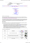
Set Throttle Input/Output Voltages
The goal of these voltage level adjustments is to match the output of the operator throttle with the controller throttle
input as illustrated below. This minimizes throttle dead zones, ensures that WOT achieves maximum controller output,
and ensures that the controller is completely shut down at zero throttle. These are one-time adjustments and once
made should never require alteration. Throttle voltage adjustments are not designed to adjust controller power,
although misadjustment can reduce power.
Voltage Range Mapping - Operator Throttle Output (ThrI) to Controller Input (ThrO)
The left figure above illustrates how the CA parameters are set near but not exactly equal to the related
throttle/controller values to ensure effectiveness in case of small mechanical and electrical variations with time and
temperature. For instance, ThrI->MaxInput and ThrO->MaxOutput are adjusted so the CA detects max operator
throttle slightly before true WOT and accordingly delivers a bit more than the maximum controller input.
The right figure above illustrates the mapping of out-of-range inputs which can be caused by broken throttle
connections.
2013-03-14 1200 (B22)
14/39
Unofficial CA V3 User Guide
•
Breaks in the throttle Sense or 5v+ connections send the Throttle IN to 0.0v which the CA maps to
ThrO->MinOutput.
•
Breaks in the throttle Gnd connection drive Throttle IN to 5v, a dangerous failure. The CA prevents WOT
runaway by mapping voltages of ThrI->FaultVolt and above to ThrO->MinOutput.
The following steps should ensure a near optimal configuration without guesswork - there are just a few steps and no
foreknowledge of the throttle or controller are required. Please postpone alterations to these recommended settings
until the entire throttle adjustment procedure is complete and fully operational.
Note: The following adjustments are best undertaken with the bike on a stand so the motor can be run to speed
safely. Use care in making these adjustments since it is possible for high motor speeds to be accidentally applied
during the adjustment process.
1.
EITHER - New v3 Operation (CA Provides Throttle)
1.
Set ThrI->CntrlMode = Pass-thru
2.
Jot down the default settings for ThrO->UpRamp, ThrO->DownRamp , and ThrO->FastRamp.
To avoid delayed response during adjustment, set these parameters to 0.00 Sec/Vlt
(the display may change after data entry to the actual allowable minimum values).
3.
4.
Tune Thrl->MinInput and Thrl->MaxInput to match the actual throttle voltage range.
1.
Use the live Throttle In voltage display on the bottom of
the Setup Throt In screen to determine the voltages at
ZERO throttle and WOT.
2.
Transfer these readings to Thrl->MinInput and
Thrl->MaxInput . Increase/decrease the Min/Max settings
respectively by 0.05-0.10V over the actual readings to
ensure full throttle range e.g. if read
(min,max) = (1.12, 3.93) then set instead to (1.17, 3.88)
Set Thrl->FaultVolt auto-shutdown feature for damaged throttle connection.
Set Thrl->FaultVolt about half way between 4.99v and the actual measured max Throttle IN
e.g. for the example above (4.99+3.93)/2 ~= 4.5v.
5.
Adjust ThrO->MinOutput and ThrO->MaxOutput to match the controller min/max throttle input voltage
range.
Note: The basic setup procedure outlined in this step is applicable to RC ESC installations although the
units are in msec instead of volts and the initial min/max range may be ESC-specific.
1.
Start by setting min/max to 0.00V and 4.99V respectively.
2.
Use the Diagnostic Screen (left button once from Main
Display) that shows Throttle OUT. While increasing the
throttle, note the OUT voltages at which the wheel begins
to turn (min) and stops turning faster (max).
3.
Verify the max setting does not cause the controller to
shutdown from an input voltage fault. Slowly ramp the
throttle up until the controller shuts down from throttle
overvoltage fault; note the OUT voltage when this occurs
and in the next steps ensure that ThrO->MaxOutput is
at least 0.25V less than this value.
Disregard this test if the controller does not shut down (it may lack this feature).
4.
Transfer these readings to ThrO->MinOutput and ThrO->MaxOutput. Decrease/increase the
Min/Max settings respectively by 0.05-0.10V over the actual readings to ensure the controller is shut
off at zero throttle and actually reaches WOT
e.g. if read (min,max) = (1.4, 3.9) then set to (1.35, 3.95) instead.
2013-03-14 1200 (B22)
15/39
Unofficial CA V3 User Guide
5.
If necessary, fine tune the ThrO settings so there is very small 'dead zone' at zero throttle and WOT.
Verify 'dead zones' by watching Watts on Main Display while moving throttle near/at zero and WOT Watts will not change in dead zones.
6.
2.
Restore ThrO->UpRamp, ThrO->DownRamp, and ThrO->FastRamp to the default settings recorded
earlier.
OR - Legacy Operation (CA Limits Operator Throttle)
1.
Set ThrI->CntrlMode=Disabled
2.
In legacy mode, ThrI->MinInput and ThrI->MaxInput have no effect; these parameters may be left at
the default settings.
3.
In legacy mode, ThrO->MinOutput and ThrO->MaxOutput are equivalent to the CA v2.x parameters
ITermMin and ITermMax respectively. To paraphrase sections 8.11 and 8.12 of the CA v2.23 Manual:
“ThrO->MaxOutput puts an upper limit on how high the throttle over-ride will drift upwards when
none of the limit values are being exceeded. Ideally this value is set to the voltage that is considered
full throttle by the controller. For hall effect throttles, full power occurs at about 4V, and limiting the
ITerm to this value will speed up the response time of the limiting features. Allowable values are from
0 to 4.99V.”
“ThrO->MinOutput imposes a lower bound on how low the throttle over-ride can drift downwards
when one of the limiting values is being exceeded. By preventing the over-ride signal from going all
the way to 0V, you can decrease the recovery time for the signal to go back upwards. Range is from 0
to 4.99V, and must be less than ThrO->MaxOutput.”
These values are ideally the controller throttle input voltages at which the motor just begins to turn
(actually a bit less), and stops turning faster at no-load (actually just a bit more). Unlike non-legacy
mode, there is no way to measure and determine these settings using the CA alone. Unless you have
specific knowledge of the controller throttle input voltage range, leave these settings at the defaults for
the first try and adjust for more optimal limiting operation later if necessary.
4.
3.7
Use the Diagnostic Screen to verify that the Throttle OUT voltage is equal to the configured
ThrO->MaxOutput. When underway, this value will fall towards ThrO->MinOutput as any limiting
parameter comes into play.
Test Throttle and Limit Settings
Your CA is now ready for a test ride where one or more of the limit parameters may affect the throttle output voltage.
1.
2.
Verify Throttle Adjustments:
•
Verify that at zero throttle there is no pronounced dead zone and no motor creep.
Otherwise, revisit the ThrI->MinInput and ThrO->MinOutput adjustments above.
•
Verify that at WOT there is no pronounced dead zone and that the bike delivers maximum power.
Otherwise, revisit the ThrI->MaxInput and ThrO->MaxOutput adjustments above.
Verify Limit Configuration
If the throttle is correctly adjusted and the bike still fails to achieve full power, then some Limiting Parameter
may be unexpectedly coming into play. Use the 'Limit Flag' display on the Diagnostic Screen to identify any
limits in effect (see table below). Upper case flag characters indicate which Limiting Parameter is presently
moderating throttle output and so may require adjustment. Gain Parameters are discussed in the next
section.
In legacy mode, limiting is in effect whenever Throttle OUT (plus a diode drop) is a lower voltage than that of
the operator throttle. If the bike does not achieve full power, the value of ThrO->MaxOutput may be set too
low causing limiting to accidentally be in effect in spite of Limit Flag indications. Temporarily adjust
ThrO->MaxOutput = 4.99. If this remedies the problem, then take throttle voltage measurements to more
2013-03-14 1200 (B22)
16/39
Unofficial CA V3 User Guide
accurately determine the minimum voltage necessary to achieve maximum unloaded motor speed at WOT.
Alternatively, reset ThrO->MaxOutput to the default then iteratively increase the value by 0.1v and test until
no further WOT speed improvement occurs.
Note that the speed limit flag is only asserted if you actually exceed the limit. There are other aspects of the
speed control logic that can lead to limiting or speed oscillations (next section) but that are difficult to
evaluate as causing a problem. As a result, there can be a speed-related issue with no 'S' Limit Flag.
At this point the throttle and basic limiting adjustments are complete. It remains only to adjust throttle ramping and,
if necessary, to adjust gains to minimize power oscillations.
4.0 Throttle Ramping Adjustments
Throttle ramping is not available in legacy mode.
Throttle ramping affects Throttle OUT universally and so plays a role in operator throttle, closed-loop throttle, PAS,
auto-cruise, etc. The ramping logic appears as a clamping mechanism to moderate the rate of throttle change. It only
participates when the the rate of Throttle OUT change exceeds configured limits – at lower rates it has no effect.
Although adjusting these settings to achieve desired behavior is a matter of personal preference, ramping can have
an effect on the stability of controller current and speed limiting logic. It is best to configure ramping as close as
possible to final desired values before gain adjustments are undertaken. This policy allows conservative ramping
adjustments to be made later with little likelihood of stability impact.
Adjust ThrO->UpRamp, ThrO->DownRamp, and ThrO->FastRamp as appropriate to achieve the desired throttle
response. All ramp settings are in sec/V (inverse rate) so larger values yield longer ramp times.
UpRamp is a limit controlling the maximum rate at which power can be applied – lower rates are unaffected.
This slows power application giving smoother getaways without harsh acceleration. Gear motors, mid-drives,
and powerful DD motors may benefit from higher values to moderate power on dead starts.
FastRamp is similar to UpRamp and is set to a faster rate. The CA uses FastRamp when current is less than
2A to allow the motor to quickly come to speed if the vehicle is already underway. The CA switches to
UpRamp when current is 2A or greater (load is detected) to apply slower ramping.
DownRamp is a limit controlling the maximum rate at which power can be reduced – lower rates are
unaffected. This generally should be set to the default or faster so closing the throttle has a fairly immediate
effect. Certain types of drive systems may benefit from slower ramp times. Ebrake application bypasses
DownRamp and always has immediate effect.
ThrO->UpRamp is the only preset-specific parameter so all other ramping adjustments will be shared across presets.
5.0 Gain Adjustments: Minimizing Surging or Speed Oscillations
Control overshoot and power oscillations may occur whenever the Cycle Analyst provides current, power, or speed
limiting. Alternate closed-loop throttle modes (e.g. Current Throttle) where the throttle sets a limit so limiting is
always in effect are just special cases of classic 'maximum value limiting' (e.g. MaxCurrent).
2013-03-14 1200 (B22)
17/39
Unofficial CA V3 User Guide
The Cycle Analyst utilizes PI (proportional-integral) and PID (proportional-integral-derivative) controllers for
current/power and speed limiting respectively. The behavior of this controller logic is determined by gain settings that
affect the degree of feedback from measurements of battery voltage, shunt current, and speed. These gain settings
allow the Cycle Analyst to be tuned for proper operation across a wide range of vehicle powers and weights. Although
the default gain settings will prove suitable for many low to moderate powered builds, some vehicles will require
additional adjustment (e.g. those with high power to weight ratios).
Throttle correction is controlled by the gain setting of whichever Limiting Parameter is in play (see table in preceding
section). For example, if PLim->MaxAmps forces limiting then PLim->AGain will control throttle correction. If power
oscillation is present, inspect the 'Limit Flag' display on the Diagnostic Screen while surging is underway. The Limit
Flag(s) changing state in synchronization with the surging will indicate the gain settings of interest.
All gain settings are global parameters and so will be shared across presets.
In legacy mode, slow limiting correction can also occur if ThrO->MinOutput or ThrO->MaxOutput are set far from
the desired values described earlier (i.e. default settings may work, but suboptimally). This can cause correction
delays as the CA limiting voltage takes time to change across the 'dead zone' between the actual and optimal
settings. This problem mode can be identified by examining the Throttle OUT voltage on the Diagnostic Screen and
watching if there is excessive change with no apparent effect on bike power - followed by the desired correction. If
necessary, adjust the ThrO parameters as described above.
5.1
Current and Power Limiting (Current and Power Throttle)
For these modes, reducing the related gain setting minimizes overshoot and dampens oscillation, while excessive
reduction leads to sluggish response. Adjustment is straightforward. Here are specific recommendations for each gain
setting:
Grin Tech V3 web page:
AGain: Feedback gain for the current control loop. Generally it should be increased until you start to feel the current
limit being rough or oscillating, and then scaled back about 30%.
WGain: Same story as A Gain above, only now applied to the power limiting feedback loop.
It may also be worth a small gain adjustment if the bike appears to ride smoothly but the Amp/Watt displays fluctuate
widely around the limit setting - over/under fluctuations should be modest and easily tracked by eye.
5.2
Speed Limiting (Speed Throttle)
Here is a summary of the three speed-related gain adjustments:
Grin Tech V3 web page:
IntSGain: Integral feedback gain for speed PID control loop. Lower values give smoother control and less likelihood of
hunting, but can increase the time it takes for the speed limit to stabilize.
PSGain: Proportional feedback term for speed control loop. Displayed in terms of Volts / (mph or kph). So if it is set
to 0.5V/kph, then for each km/hr you go above the speed limit, the throttle output will immediately drop by 0.5V.
DSGain: Differential feedback term for speed control loop. This is used to dampen oscillations from speed limiting.
Because the speed PID controller tries to anticipate limiting situations before they occur, the some vehicles may
experience cutouts during hard acceleration. The problem arises as the vehicle rapidly accelerates toward the speed
limit and the Cycle Analyst preemptively reduces the throttle to avoid overshoot – even though the limit has not yet
been reached. This cutout symptom is an indication that the DSGain setting is too high (too much 'future sense'). The
CA cannot actually discern that meaningful limiting is in effect and so the associated 'S' limit flag gives no indication.
The more complex PID controller employed for speed limiting is of a type that classically presents a greater
adjustment challenge. If speed-related surging or power cutouts occur, apply one of these two remedies:
1.
If Speed Throttle or enforcement of SLim->MaxSpeed are desired, please follow the tuning procedure for the
speed controller outlined in 'Appendix B. Tuning Speed Control Gain Parameters'.
2.
If Speed Throttle and maximum speed limit enforcement are not required, disable the speed control logic:
set SLim->MaxSpeed to the maximum value, IntSGain = 1, PSGain = 0, DSGain = 0.
2013-03-14 1200 (B22)
18/39
Unofficial CA V3 User Guide
6.0 Advanced Features
The following sections describe features that can be utilized once basic setup is complete.
6.1
1.
Closed-Loop Throttle Modes
Overview: If in non-legacy mode, the CA offers three additional
closed-loop throttle modes that can give substantially improved
throttle control:
•
Current Throttle
•
Power Throttle
•
Speed Throttle
These are 'fly by wire' modes where the operator throttle is not passed through to the controller but rather
sets 0-100% of the associated limit parameter as a target for the CA to achieve. The CA alone supplies the
controller throttle and receives feedback from the shunt or speed sensor to determine how well it has done in
achieving that target. It then adjusts the controller throttle in a closed loop to cause the output to track the
desired rider throttle input. Because the load is reflected through the motor back to the shunt, the CA will
maintain the target current regardless of changes in terrain.
In this mode any unpleasant nonlinearities in the controller-motor
curves are of little consequence as
adjustments to achieve the desired
output are exclusively the
responsibility of the CA, not the
rider.
For example, in the case
of Current Throttle, if
PLim->MaxCurrent is set to 50A
then WOT is 50A. Assuming the
rider throttle is more or less linear,
adjusting the throttle to 10%
rotation yields a predictable controller output of 10% of 50A or 5A.
The table below shows the available throttle modes - all but Pass-thru are closed loop. The columns show the
feedback source and the relevant parameters for each mode of operation. To get the smoothest and most
consistent operation it may be best to set the 'other' limits as loosely as possible (i.e. set as true max safety
limits) so only the single throttle limiting parameter is generally in play. Throttle Mode Summary
Note that the CA Speed Throttle is completely different than the Infineon controller throttle logic which is
often referred to as a 'speed throttle'. The CA Speed Throttle is a true closed loop control system that
measures the bike speed and corrects for variations. In contrast, the Infineon throttle uses open loop control
to vary phase PWM duty cycle according to the input throttle voltage without regard for directly measured
bike or motor speed; this results in varying speed with load and terrain.
Current and Power Throttle modes have a familiar feel and are the easiest to set up and control.
2013-03-14 1200 (B22)
19/39
Unofficial CA V3 User Guide
2.
Adjustment: If surging or power oscillations are present after selecting a closed-loop mode, revisit
' 5.0 Gain Adjustments: Minimizing Surging or Speed Oscillations'. Existing ramping settings are unaffected.
Note: It may be useful to use a new preset when tuning a new closed-loop throttle mode so that operation in
PassThru mode remains readily available until the new mode operates satisfactorily.
3.
Hall Throttle Linearity: The closed-loop control strategy cannot
compensate for throttle non-linearities. Many hall-effect throttles
are intrinsically non-linear and so will compromise the effectiveness
of these throttle modes. Better quality hall throttles with a long
linear magnet or resistive throttles like a Magura will yield the best
results.
4.
Limit Flag Behavior: It is normal when using any closed-loop
throttle mode for the corresponding Limit Flag on the Diagnostic
Screen to show almost continuous limiting - even at standstill.
Similarly, in the case of Speed Throttle, the main screen 'kph/mph'
units will flash almost continuously. This occurs because these modes are implemented using the normal
limiting logic except that internally the logic input is assumed to be WOT and the operator throttle instead
scales 0-100% of the Limit Parameter. As a result, the CA is always trying to go WOT but is almost always
being restrained by the adjustable throttle limiting. This asserts the Limit Flag.
5.
Spoke Magnets and Speed Throttle: Using Speed Throttle at very low speeds can be problematic if using a
wheel pickup in the standard configuration. With only a single spoke magnet, the Cycle Analyst gets a speed
update only once per revolution or about once every two meters. Off the line or at very low speeds, this is
inadequate for smooth speed control. There are two means to remedy this:
6.2
1.
Set SLim->StrtSpeed to 5 or 6mph so that the Cycle Analyst will not attempt Speed Throttle control until
the Sp pulses are arriving with adequate frequency.
2.
Add more spoke magnets. These need not be placed exactly evenly. Each magnet generates a speed
update, reducing the ground speed necessary to achieve adequate pulse frequency. As few as three or
four magnets will give good results. Additional magnets may be ordered from Grin Tech.
Auto-Cruise Control
The cruise control feature is firmware-only. The option is enabled by setting
ThrI->AutoCruis from Off to one of several preset hold times. This is a
preset-specific parameter that determines the period of time that the
operator throttle must be held stationary to engage auto-cruise.
The ThrI->CruiseHld parameter determines the allowable (+,-) voltage
variation for the operator throttle in order for it be considered
'held stationary' for the AutoCruis period.
When auto-cruise engages, a second blinking 'ghost' indicator appears on
the throttle bar graph at the 'set' cruise level. The normal solid slider
continues to move with the throttle. The appearance of the blinking slider
gives a visual indication that cruise is engaged and the throttle can be
released.
Auto-cruise disengages when ebakes are applied or when the operator throttle is moved in the direction of WOT
regardless of its present position.
Auto-cruise can be used with any throttle mode: PassThru, Current, Power, or Speed.
2013-03-14 1200 (B22)
20/39
Unofficial CA V3 User Guide
6.3
Auxiliary Pot
1.
Grin Tech:
“The purpose of this input is to allow on-the-fly adjustments of one of the CA's limit values
(i.e. the current limit, speed limit, or power limit). That can be accomplished either via a potentiometer, or for
discrete settings with a multi-position switch and resistor dividers. A 0-5V signal range is allowed, and it
defaults to 5V if left disconnected.”
2.
Modes: The AUX Pot input can operate in either of two modes determined by Aux->Function:
• Limits: The applied voltage scales a limiting parameter or
• Presets: The applied voltage selects one of the available mode presets.
1.
Limits Mode: This provides a means to apply an external control voltage (max range 0-5v) to provide a
0-100% scale of the limiting parameter specified by Aux->ScaleLim.
Aux->ScaleLim
Amps Lim
Power Lim
Speed Lim
PAS Level
POT input controls
0-100% of parameter
PLim -> Max Current
PLim -> Max Power
SLim -> Max Speed
Trq -> Asst Level
Any device with a voltage output in the range of 0-5v may be used. Examples of external controls:
Potentiometer: This is the most basic adjustment technique. R1 = 5K
linear taper pot. To prevent contaminants from entering the device
either use a 'sealed' type pot, enclose it completely, or seal it using a
product like Liquid Lectric Tape or Plasti-Dip.
Throttle: A resistive or hall effect throttle may be substituted for the
potentiometer. For instance, a thumb throttle may be located on the
left side and be modified so it stays in position when adjusted.
3-Position Switch: This is the Cycle Analyst version of the conventional controller 3-position switch.
The example implementations below provide three settings: Low, Medium, and High. The LMH version is
better suited to rocker switches while the LHM version may be better suited to toggles where the center
position is a little fussier to achieve. R1 = R2 = 5K 20 turn trimpots, R3 = 7.5K, R4 = 10K.
2013-03-14 1200 (B22)
21/39
Unofficial CA V3 User Guide
Depending on the Aux->ScaleLim setting, these sample circuits may be used as 0-100% PAS Assist
knob, a 0-100% speed limit knob, a 3-position current or power limit control, etc. These examples can
be combined. For instance, the 'Low' trimpot of the 3-position switch might be replaced with a 5K linear
pot to add an adjustable low setting or to do double duty as a PAS Assist Level in a different preset.
These particular sample circuits assume Aux->MinAuxIn = 0.0v and Aux->MaxAuxIn = 4.99v; other
circuits may have different requirements. Devices like a hall throttle are best configured based on
measurements from the AUX Pot Setup preview screen - see below.
2.
Presets Mode: This provides on-the-fly preset selection using external switch control. The mode preset
is selected by dividing the voltage range between Aux->MinAuxIn and Aux->MaxAuxIn into the same
number of equally sized voltage bands as there are presets (1,2, or 3) and determining in which band
Vpot lies. Input voltages below/above the configured min/max range are considered to fall within the
adjacent lower/upper voltage band respectively. The highest voltage band is preset #1.
When a new preset is selected, a “CHNG MODE PRESET” screen is briefly displayed.
The left and middle diagrams above will select from two presets with the middle circuit being perhaps a
bit more noise immune. The right diagram uses R1 = R2 = 4.7K resistors and will select from three
presets. These particular sample circuits assume Aux->MinAuxIn = 0.0v and Aux->MaxAuxIn = 4.99v
although other circuits might use a different range.
3.
Live Data Display: The AUX Pot Setup preview screen provides a
live data display of Vpot which can be used to dial in trimpots or
inspect voltages as controlling switches/pots are manipulated.
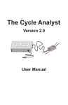
4.
Throttle Scaling: When using both closed-loop throttle and Aux
POT features it is important to configure
Aux->ScaleLim and ThrI->CntrlMode to use the same limiting
type to obtain automatic throttle scaling. Throttle scaling causes
the throttle maximum to be limited by the Vpot value instead of
the configured limiting parameter maximum. These matching
settings are shown above in the 'Throttle Mode Summary' table.
For example, if
PLim->MaxCurrent=50A,
Aux->ScaleLim=AmpsLim,
ThrI->CntrlMode=Current,
Vpot (min,max) is (0v,5v), and
Vpot = 1.0v (20% of 5v), then
the controller will be limited to
20% of 50A or 10A.
The sample plots to the left show
the controller current limit vs
0-100% throttle rotation for three
different Aux POT limit settings
(20%, 70%, and 100%). In each
case WOT is scaled to the existing
Aux POT limit and the throttle
effect is linear, ZERO to WOT.
2013-03-14 1200 (B22)
22/39
Unofficial CA V3 User Guide
In contrast, the plot to the right shows
an example where throttle and Aux POT
have differing limit parameters
(e.g. current and power). In this case
there is no throttle scaling; instead, the
separate Aux POT limit imposes a ceiling
above which further throttle rotation has
no effect. This causes an operator throttle
'dead zone' identical to that produced by
the simple limiting of legacy mode (V2)
operation.
5.
6.4
Electrical Characteristics: To avoid
affecting external resistor dividers, the
Aux POT input is the only input that does
not have a pull-up or pull-down resistor
on the PCB. The applied impedance
should be no more than 10K for the A/D
converter to achieve full 10bit accuracy.
eBrake
1.
Grin Tech:
“This input has an onboard pull-up to 5V to be used with an ebrake cutoff switch. When the signal is shorted
to ground, the CA thinks that your brake levers are depressed and forces the CA's throttle output to 0V.“
2.
Device Connection: If you have simple throttle cutout on ebrake, then you may connect your ebrake to the
Cycle Analyst using the connector illustrated above. This will work in either new or legacy modes. However, if
you are using controller regen or auto-cruise that rely on direct ebrake input, then you must run the ebrake
connection to the controller instead of the Cycle Analyst.
3.
Operation: The Cycle Analyst EBK input is asserted when low. This causes ThO to be driven to 0.0v; no other
operation reduces ThO lower than ThrO->MinOutput making it possible for an external circuit to examine the
ThO level to discriminate between throttle ZERO and ebrake application.
Ebrake application also suppresses ThrO->DownRamp, sending ThO to 0.0v immediately.
4.
When EBK is asserted, an animated eBrake graphic replaces the Throttle Gauge on the main display
(see 'Main Status screen').
5.
Electrical Characteristics: The EBK pad ties to a microprocessor port through a 1K resistor. The pull-up
current is approximately 150uA with an effective (min,typical,max) pull-up resistance of (15K,30K,200K). The
threshold voltages at the EBK pad are approximately 1.5V to activate and 2.1V to release. Either a mechanical
switch or hall effect device makes a suitable sensor.
2013-03-14 1200 (B22)
23/39
Unofficial CA V3 User Guide
6.5
1.
Pedal Assist
Grin Tech:
“10V: This is an output pad specifically for supplying power to the THUN torque sensing bottom bracket. It
can potentially be used as a low current power source by other PAS sensors too, however care must be taken
as this supply is not fused or protected, and a short to ground will damage the CA. Current draw from this
line should be limited to 15mA max and only with 48V or lower batteries.
Pedal Sensor Input (RPM): This is a digital input for a pedal cadence sensor. It has an onboard pull-up resistor,
so it can work with an active hall effect device or a simple magnet and reed switch pickup.
Pedal Direction Input (Dir): This is used to distinguish between forwards and reverse pedal rotation for PAS
sensors that provide this signal. It can support both a pure direction signal (e.g. 5V = fwd, 0V = reverse), or
a quadrature type encoder such as on the THUN sensors.
Torque Sensor (Trq): This is a 0-5V input for a torque signal. The human pedal torque can be measured either
via a torque sensing bottom bracket (THUN, FAG), or via a DIY tension meter on the bike chain itself. The
torque signal here is multiplied by the calculated pedal RPM signal to derive the human power on the CA, and
to provide proportional torque assist.”
2.
Sensors: The pedal assist connector is primarily designed for the THUN torque sensing bottom bracket but
also supports similar units from FAG from Germany and GreenTrans from Taiwan. Alternatively, it can use a
simple PAS cadence sensor providing a 0-5v pulse output. The direction input can be a Fwd/Rev level or a
pulse input providing quadrature encoding in concert with the RPM signal. PAS rings are available with varying
numbers of poles - typically less than 12. The more magnets or pulses per wheel rotation, the faster the CA
can detect and react to start of pedaling.
Note: The PAS sensor must have a pulse output. Sensors providing a throttle-compatible analog voltage
output cannot be used. PAS wheels typically do not have a direction output to detect pedaling backwards
although some may instead only send pulses pedaling forward. See 'Appendix D. Tips and Tricks' for a means
to add a second pickup to simple PAS wheels to discriminate direction.
3.
Sensor Power: Certain PAS cadence sensors utilize hall sensors instead of reed switches. These sensors
require a +5v supply which may be obtained by various means:
• A +5v tap may be added to either mating JST connector for CA throttle or Aux POT.
• The white +10v power lead of the CA-TRQ/PAS connector may be re-purposed by relocating the
connection to either of the Throttle or POT +5v pads of the CA PCB.
• A +5v tap may be added to the mating JST connector for the controller throttle.
IMPORTANT: THUN Power Requirements: Please pay particular attention to the current limit of the CA
+10v supply when powering a Thun or similar sensor. Higher battery voltages require the use of an external
DC/DC converter to power either the THUN or the Cycle Analyst.
Please inventory the total CA current requirements and choose an appropriate power strategy as described in
' 6.8 Cycle Analyst as a Power Source' when adding any sensor or accessory to the CA. This is particularly
important for torque sensors or dual hall effect PAS sensors because of the higher current requirements.
2013-03-14 1200 (B22)
24/39
Unofficial CA V3 User Guide
4.
Sensor Operational Overview: PAS cadence sensors are 'pedaling detectors' and provide a means to
activate a constant non-proportional power assist, that is, the assist is constant regardless of pedal RPM.
Torque sensors provide the same signals as PAS sensors but add a torque signal that varies linearly with
torque. This variable signal can be used to provide proportional assist according to applied rider effort. If the
Cycle Analyst is configured to ignore the torque signal, a torque sensor will operate as a simple PAS sensor.
The simple on/off nature of assist from a PAS sensor warrants no special logic beyond enabling assist only
when the optional direction signal indicates 'Fwd'. In the case of torque sensors, the Cycle Analyst logic
requires that the rider actually be pedaling to enable assist. Simply standing on the pedals to generate a large
torque signal is ineffective. Measured rider torque is averaged over each full pedal rotation rather than over a
specific time period. This eliminates undulation from aliasing of the average rate with pulsating pedal torque.
5.
PAS Configuration: Individual parameters of the Setup PAS and Trq sections are described on the Grin Tech
Site. Although configuration is generally straightforward, the following presents detailed information about
select parameters.
1.
PAS->Plrty controls Fwd/Rev direction determination for both level ( Dir) and quadrature (RPM/Dir)
2.
If there is no quadrature sensor, then PAS->Quadrtr must be disabled. If there is a quadrature sensor
then PAS->Quadrtr may be either enabled or disabled. If PAS->Quadrtr is disabled then only the falling
signal transitions are used to detect pedaling, whereas both rising and falling edges are used if it is
enabled. This improves pedaling detection responsiveness by doubling the number of indications per
revolution.
3.
signal types.
Details of PAS->PAS Mode parameter values:
In all modes, if throttle is applied even a small amount while pedaling, PAS assist is ignored and the
throttle alone determines the output.
1.
“OR” Modes – PAS and throttle are always enabled and either provide power. PAS->MxThrotSpd
has no effect in these modes.
1.
RPM | Throt
• Pedaling without throttle causes full throttle to be applied until a limiting parameter comes into
play. In this mode the standard limit parameters PLim->MaxCurrent, PLim->MaxPower, or
Slim->MaxSpeed serve as adjustments for assist level.
• If throttle is applied, it operates normally and disables PAS.
Since the same limits remain in force, WOT gives the same assist as PAS.
2.
Trq | Throt
• Pedaling without applied throttle results in proportional PAS assist power according to
Trq->AsstLevel times the detected torque.
• If throttle is applied, it operates normally and disables PAS.
2.
“AND” modes – The throttle is enabled without pedaling at speeds up to PAS->MxThrotSpd.
At higher speeds, pedaling is required to enable the throttle. These modes in conjunction with
PAS->MxThrotSpd can provide compliance with a variety of pedalec legal requirements.
1.
RPM & Thot – in this mode there is no PAS power assist
• Below PAS->MxThrotSpd, the throttle is enabled and operates normally.
• Above PAS->MxThrotSpd, if pedaling is detected, the throttle is enabled.
2.
Trq & Throt
• Pedaling without applied throttle results in proportional PAS assist power according to
Trq->AsstLevel times the detected torque.
• Below PAS->MxThrotSpd, the throttle is enabled and if applied operates normally and
disables PAS.
• Above PAS->MxThrotSpd, if pedaling is detected, the throttle is enabled and if applied
operates normally and disables PAS.
2013-03-14 1200 (B22)
25/39
Unofficial CA V3 User Guide
6.
Live Data: There are two Setup preview screens for PAS support –
the PAS Sensor screen for the RPM and Dir inputs and a second
screen for Trq, the proportional voltage torque input. Both show
live data as in the illustrations to the right. The small up/down
arrows on the PAS screen show the hi/low state of the RPM and
Dir inputs. The torque input voltage and equivalent converted
torque value are shown on the Torque Sensor screen. Pressing a
pedal with the rear wheel blocked will show a torque voltage while
turning the crank will show the small 'P' (RPM) arrow going
up/down as magnets pass the sensor head. Depending on the PAS
sensor, the small 'D' (Dir) arrow may or may not change
('yes' for Thun, 'no' for PAS wheels).
7.
Torque Offset: The nominal torque sensor offset voltage for zero
torque should be set at installation time and may need to be zeroed
again from time to time. Trq->TrqOffset operates much as does
Cal->ZeroAmps - Press-Hold to store the present torque output
voltage as the baseline for zero torque.
8.
External 'Assist Level' Control: An external Assist Level adjustment knob can be added using the AUX Pot
input – see ' 6.3 Auxiliary Pot'. This is configured differently for PAS and torque sensors.
1.
PAS cadence sensors provide on/off control of a fixed assist level that is determined by the standard
current, power, and speed limit parameters. To configure:
• Set Aux->Function = Limits
• Set Aux->ScaleLim = one of { PowerLim | AmpsLim | SpeedLim }. This will cause the control knob
to scale one of PLim->MaxPower, PLim->MaxCurrent, or SLim->MaxSpeed respectively from
0-100% of the configured value. By this means PAS assist will encounter the reduced limit and hold
assist to that level.
• Since the throttle is also affected by these limits, it may be best create a dedicated PAS preset with
a reduced limit so that less restricted throttle output is readily available in other presets.
2.
Torque sensors provide proportional assist and are specially supported by AUX Pot. To configure:
• Set Aux->Function = Limits
• Set Aux->ScaleLim = Pas Level. This will cause the control knob to scale Trq->AsstLevel
0-100% of the configured value of Watts per Newton-meter, reducing the number of assist Watts
provided for each Nm of torque.
Please see 'Appendix D. Tips and Tricks' for an alternate means to install an Assist Level control for PAS
cadence sensors.
9.
Thun Specifics: Grin Tech provides a compatible Thun X-Cell RT digital bottom bracket with the proper
connector to mate with the CA-TRQ/PAS JST-5. The connector wiring is as follows:
The Thun X-CELL RT digital generates 8 pulses per rotation and has a power requirement of 7-16v at 20ma.
The nominal zero Nm offset is 2.5v and the max (+) torque is 200Nm at 4.5v. The RPM and Dir signals are
quadrature encoded as cosine and sine waveforms respectively.
2013-03-14 1200 (B22)
26/39
Unofficial CA V3 User Guide
6.6
Temperature Sensor
1.
Grin Tech:
“This is the input for a temperature signal. The pad has a precision pull-up resistor to 5V, so it can be used
with a simple 10K NTC thermistor between the pad and ground. Alternately, an actively driven signal from 05V (such as from an LM35 type IC) can be fed to this pad and scaled linearly into a temperature reading.”
2.
Limiting Operation: The Cycle Analyst limits PLim->MaxCurrent
linearly 100-0% as the temperature rises in the configured danger
range. Maximum current begins to be limited (100%) at
Temp->ThrshTemp and is finally reduced to zero (0%) at
Temp->MaxTemp. The T Limit Flag indicates that temperature
limiting is in effect.
3.
Supported Devices: This input can be supplied by either a 10K
NTC thermistor or a linear temperature sensing IC such as an
LMx35 (datasheet) that operates like a zener diode. Note that
the LM35 (datasheet) is not part of this device family and is not
formally supported. Unfortunately, the LM35 may come preinstalled in some motors as the only option. In such cases, CA/LM35 electrical incompatibly can be remedied
by minor modification of the Cycle Analyst PCB. See 'Appendix D. Tips and Tricks'.
4.
Thermistor Selection: The present firmware has a hard coded calibration for 10K NTC thermistors with a
beta constant of 3900. This gives workable accuracy for beta values of 3800 - 4000.
5.
Electrical Characteristics: The NTC input is pulled up to 5v via a 5K resistor. This value provides forward
current for devices like the LM335 to give reliable linear response while giving good sensitivity for 10K
thermistors in the 80-100 degC temperature range.
6.
Ground Reference: It is recommended that the thermistor ground be tied to the provided CA PCB Gnd pad
and not be shared with other devices. This policy minimizes unwanted voltage offsets between the CA and
thermistor grounds which will affect the measured sensor voltage. For example, temperature errors can occur
where a motor temp sensor shares a Gnd lead with hall sensors (controller Gnd) and a high current headlight
is run from the CA external power jack causing the CA ground reference to rise slightly above that of the
controller.
7.
Jitter: Some display jitter is not unexpected but does not adversely affect measurement accuracy or limiting
functions. The jitter is due in part to the absence of display averaging in firmware through B22.
Excessive jitter may be reduced by soldering a monolithic 0.47uf capacitor across the thermistor NTC and Gnd
pads. However, firmware alterations planned for B23 should eliminate visible jitter and make the capacitor fix
unnecessary.
2013-03-14 1200 (B22)
27/39
Unofficial CA V3 User Guide
6.7
High Voltage Vehicle Support
1.
Grin Tech: “Battery Power (V+): This is the V+ supply of the battery pack, used both to power the CA and
also to sense the battery voltage. The maximum supply voltage with no accessories is 150V, but this must be
derated if there are other devices (Torque Sensor, Input Throttle etc) also drawing power from the CA.”
2.
High Voltage Operation: Voltages up to 500vdc may be monitored by redirecting the CA voltage measuring
functionality from the power supply +V PCB pad to the Vex pad. The +V pad continues to supply CA power.
Locate the three adjacent solder pads shown above and relocate the solder bridge from the
[middle + bottom] pads to the [middle + top] pads. With this modification, the +V pad only supplies power
while the voltage sense input is taken from [Vex and external divider] instead of [+V and on-board divider].
Note: Rev 2 boards may have an SMD capacitor hand-soldered from C11 to the middle/bottom 'bridge' pads.
Remove this capacitor.
An external resistor divider must be provided as shown to scale the monitored voltage to 0-5v with R1 limited
to no more than 10K. Set Cal->VScale to the voltage scaling ratio (R1 + R2)/R1.
For instance, if (R1, R2) = (4.7K, 220K) then Cal->VScale = 224.7/4.7 = 47.81v/v for a maximum monitored
voltage of 5v x 47.81v/v = 239.05v. Fine tune Cal->VScale as needed so the V3 voltage reading matches
that of an attached DMM.
3.
IMPORTANT: Non-Isolated CA Power Supply: The CA V3 design requires that the CA power and
monitored voltage share a common ground.
High voltage vehicles normally isolate the 12v accessory system as a safety precaution. Because the V3
voltage sensing circuit shares a common ground with the monitored high voltage (motor) power, it is
recommended that a separate small DC/DC converter be driven by the high voltage source and used to power
the V3. The converter must be capable of supplying 10ma plus power for accessories (THUN, etc).
When a DC/DC converter is used, the converter ground must be common with the CA ground. If the converter
is isolated, the isolation must be defeated by tying the converter negative output to Vbatt(-).
4.
IMPORTANT: Forcing a Data Save: Data is saved to EEPROM when the monitored voltage falls below
Pref->V Shutdown. Since the voltage monitor is now divorced from +V, turning off the vehicle must both
remove power from the CA as well as so reduce Vex as to trigger a data save prior to CA shutdown.
A simple approach is to tie the external divider Monitored Voltage line to the switched high voltage power
supplying the CA DC/DC converter. Opening the switch will allow R1 to pull down Vex, forcing the save.
2013-03-14 1200 (B22)
28/39
Unofficial CA V3 User Guide
Typical remote sensing configuration with alternate Cycle Analyst power
6.8
Cycle Analyst as a Power Source
The CA can provide power to other devices by three means:
1.
The +5v bus available on PCB pads is unfused and can
supply power to the throttle, custom Aux POT switches,
etc.
2.
The +10v bus available on the PCB is unfused and
primarily intended for use with PAS and torque sensors.
3.
The external DC Power Plug is attached to VF and
supplies V+ via a 1A auto-resetting polyfuse.
The CA V3 uses stacked 10v and 5v regulators so the current
limit is calculated by summing current for all 5v and 10v
accessories together instead of addressing two separate limits.
'Accessories' are any devices drawing power from the PCB
excluding the external DC Power Plug.
The CA V3 can supply current to accessory devices as shown in
the table below according to:
Max = (1500mw/(Vbatt-10v)) – 10ma.
The current limit decreases with increasing battery voltage.
Table of Maximum Total Accessory Current for CA Supply Voltage Applied to Pad V+
2013-03-14 1200 (B22)
29/39
Unofficial CA V3 User Guide
Typical accessory current requirements are shown in the table to the left.
For instance, an installation with a hall throttle, Thun BB, preset switch, and two
hall ebrakes requires:
5ma + 20ma + 0.5ma + (2 x 5ma) = 35.5 ma
The preceding 'V+ vs Imax' table shows this configuration can be supported by the
Cycle Analyst for V+ voltages up to 42v.
Either of two strategies may be applied for battery packs above this maximum voltage:
•
power one or more accessories from an alternate source, or
•
power the CA from a lower voltage source to raise the available current it can supply.
1.
In the first case, additional 5v+ power can drawn from the controller throttle connector to power hall sensors,
etc. If there is a Thun BB or similar 10v sensor and a large current shortfall, then an external DC/DC
converter can be used to power the device(s). In these cases, the accessory power (+) connection is
redirected to the alternate source but the ground and device output signal lines run to the CA connectors
normally.
2.
In the second case, Vbatt is stepped down via a DC/DC converter and used to reduce the CA power supply to
the extent that the V3 can supply the needed accessory current requirements itself. Since the CA is no longer
powered by Vbatt, it is configured as if in a high voltage environment, driving Vex from Vbatt via an external
resistor divider. For details see ' 6.7 High Voltage Vehicle Support'.
Whenever a DC/DC converter is used, the converter ground must be common with the CA ground. If the converter is
isolated then the negative converter output connection must be tied to Vbatt(-) to defeat the isolation.
See 'Appendix D. Tips and Tricks' for additional DC/DC converter information.
2013-03-14 1200 (B22)
30/39
Unofficial CA V3 User Guide
6.9
Serial Data Port
1.
Encoding/Signal Levels: The Tx/Rx serial ports operate at 9600 baud with 8 bits, 1 Stop bit, and no parity
at 0v/+5v TTL levels.
2.
Live Data Stream: In normal operating mode a serial data stream is transmitted from the serial port. This
stream may be captured by a Cycle Analogger or similar device (there is no handshake) and contains
TAB-separated data as described in the following table. The data rows are sent periodically at the rate
configured by Pref->RS232.
Col
1
2
3
4
5
6
7
8
9
10
11
12
13
Headin
g
Ah
V
A
S
D
Deg
RPM
HW
Nm
ThI
ThO
Acc
Lim
Description
Amp hour
Voltage
Amperes
Speed
Distance
Temperature degC
PAS RPM
Human Watts
Thun Newton-meters
Throttle In Voltage
Throttle Out Voltage
Acceleration
Limit Flag Characters
3.
Interface Cable: The standard Grin Tech CA V3 programming cable (pn: CA3-USB) is an FTDI
TTL-232R-5V-AJ and is best ordered with the CA V3 to facilitate firmware updates.
See the Grin Tech site for USB->TTL converter cable ordering and device driver download information.
4.
External Memory Access: Using the bootloader, all of the V3 EEPROM may be accessed externally via the
serial interface. This supports loading new firmware as well as external inspection and configuration of Setup
parameters. See these posts [1, 2] for bootloader protocol and EEPROM parameter layout. For operation of
the updater application see 'Update CA with Most Recent Firmware'.
2013-03-14 1200 (B22)
31/39
Unofficial CA V3 User Guide
Appendix A. CA V3 Throttle OUT to Controller Connection
Justin on Endless-Sphere.com: “With the V3 CA devices, the functionality of the CA now includes not just throttle
limiting, but actually driving the controller's throttle signal directly, and this is NOT possible if there is a diode inline
with the throttle signal. So, if you have a CA-DP compatible controller and want to use the CA-V3 device as your new
throttle, you will need to do a bit of modification. Here are 3 approaches:
1.
Swap pins around so that the green wire
from the CA-DP goes into the controller's
regular throttle input. You can either do this
at the CA-DP plug end as shown, or you
could do it on the controller end.
2.
Insert a short between 5V and your throttle
signal. This way the throttle signal is being
pulled high by the short circuit, and so the
CA only needs to pull the signal down from
there which it can do via the diode. This
method is easiest for sure, however, it is
crucial that you only do it if your controller
has a proper over-throttle voltage fault.
Otherwise, if you unplug the CA then the
controller will take off full tilt as the throttle
input is at 5V. You want to be sure that the
controller treats this situation as a fault and
shuts down.
3.
Open up the controller and replace the diode with a ~500-1000 ohm resistor. Depending on where your
controller is from, the diode may be a surface mount device on the PCB or a clearly obvious inline diode to the
green CA wiring.
While you could in
principle completely
short out or bypass
the diode, this isn't
recommended as then
the CA will usually be
directly connected to
the microchip which
can be an issue if your
ground connection
fails. A 500 to 1000
ohm resistor will
provide some
protection.”
2013-03-14 1200 (B22)
32/39
Unofficial CA V3 User Guide
Appendix B. Tuning Speed Control Gain Parameters
The Cycle Analyst speed limiting is implemented as a classic PID (proportional-integral-derivative) controller. There
are three interacting gain parameters that can make configuration somewhat challenging. The procedure presented
below should give a good working configuration without trial and error. Bikes with high power to weight ratios may
benefit from additional tuning using this configuration as a baseline.
The table below shows the three gain parameters and the effects of increasing each individually. 'Setpoint' refers to
desired or limiting speed.
Feedback
Error
Initial Rise
Time to
Setpoint
Setpoint
Overshoot
IntSGain
Integral
Accumulated Past
decreases
PSGain
Proportional
Present
decreases
Parameter
DSGain
Derivative
Projected Future
small change
Settling
Time
Stability
increases
increases
degrades
increases
small change
degrades
decreases
improves for
small values
then degrades
decreases
The plots below illustrate some typical behaviors on getaway with Speed Throttle. Some initial overshoot is normal
and desirable - the idea is to achieve a responsive initial rise time, minimum overshoot, reasonably rapid settling
time, and stable (non-oscillating) behavior. These are interacting features, so achieving balance is the goal.
The red plot shows an unstable underdamped oscillating response that may never converge on the setpoint. In this
case there is likely either to much PSGain and/or not enough DSGain - the controller is continually overshooting the
setpoint. The orange plot shows an overdamped case where PSGain and IntSGain are too low – the response
converges on the setpoint but only after a long delay with a very slow rise time – the controller has too little gain.
On the other hand, the green and blue plots show desirable DD and gear motor responses. In both cases there is
some initial overshoot followed by settling to the setpoint. The curves differ slightly because of the freewheel clutch in
the gear motor which gives a more pronounced asymmetrical control effect – the Cycle Analyst can speed the vehicle
up, but it rolls freely and slows down of its own accord. The same is true to a lesser extent for the DD case. Because
of this, the speed controller for the gear motor is adjusted to have a more damped response (less gain) to minimize
overshoot. This slows the initial rise time and the overall settling time is slightly longer.
As mentioned in an earlier section, ramping logic can have a destabilizing effect on the control logic, particularly if it is
suddenly engaged and introduces unexpected behavior into the feedback loop. Whenever possible, it is best to satisfy
slower UpRamp requirements with more conservative (PSGain) adjustments so the controller has a nominal
responsiveness in line with overall needs rather than imposing throttle ramping to restrain tuning with unnecessarily
rapid response. As a bonus, tuning for a more damped response is somewhat easier. Slower response can be
achieved in the following tuning procedure in step (4) by further reducing PSGain beyond the recommended factor
(2 or 4 depending on the driveline type).
2013-03-14 1200 (B22)
33/39
Unofficial CA V3 User Guide
Note: Please be certain to have proper ramping values in place before proceeding. This is of particular importance for
gear motors, mid-drives, and powerful DD motors since full throttle may be applied off the line resulting in driveline
stress and potentially dangerous riding situations.
Follow one of these two procedures depending on the type of driveline:
1.
2.
If driveline does not contain a freewheel clutch (e.g. DD):
1.
Set IntSGain to 1 and DSGain to zero
2.
Calculate initial PSGain = 6 x (ThrO->MaxOutput - ThrO->MinOutput) / ( Slim->MaxSpeed ).
3.
Increase PSGain to the point where overshoot and decaying oscillation occurs - (no more than 1 or 2
additional oscillatory upswings after initial overshoot before settling).
4.
Reduce PSGain to 1/2 of its value.
5.
Increase IntSGain until oscillations die out with no more than 1 or 2 additional upswings after the initial
overshoot.
6.
Increase DSGain until settled operation is just jittery (power feels rough or ratty), then reduce 30%.
If the driveline contains a freewheel clutch (e.g. gear motor):
1.
Set IntSGain to 1 and DSGain to zero.
2.
Calculate initial PSGain = 6 x (ThrO->MaxOutput - ThrO->MinOutput) / ( Slim->MaxSpeed ).
3.
Increase PSGain to the point where a single modest overshoot occurs before the speed settles.
4.
Reduce PSGain to 1/4 of its value.
5.
Increase IntSGain as large as possible without significant additional oscillations occurring after the initial
overshoot. Additional oscillations lead to increased settling time due to strongly asymmetrical control.
6.
Increase DSGain until settled operation is just jittery (power feels rough or ratty), then reduce 30%.
These procedures should give very workable settings. However, subsequent incremental adjustment iterations can
benefit from starting with pre-adjusted values compared to those of the initial untuned state. To iterate,
•
note the time from getaway to settled speed, then
•
increase PSGain somewhat and repeat steps 5 and 6.
•
Compare the new time to settled speed. Repeat until no time improvement occurs, then restore settings from
the previous iteration (i.e. back up a bit).
This second tuning phase should yield the fastest rise time with the the fastest overall settling time. This procedure
may improve responsiveness, but is not strictly necessary – as mentioned earlier, for many situations a slightly
damped response may be more desirable.
Here are some common symptoms and likely causes if 'wing it' adjustments are made instead of the procedures
outlined above:
1.
If there are (decaying) oscillations centered about the setpoint, IntSGain is probably okay but either PSGain
is too high or DSGain is too low. Try increasing DSGain. If this leads to jittery power or does not reduce the
oscillations, then restore DSGain and instead reduce PSGain.
2.
If the rise time is slow and the output is on the average below the setpoint until it has settled, then IntSGain
is too low.
3.
If the initial rise time is too slow or there is negligible overshoot and oscillation, PSGain and IntSGain are too
low.
4.
If there are cutouts when accelerating, DSGain is too high. Repeat the adjustment of step (6) above.
2013-03-14 1200 (B22)
34/39
Unofficial CA V3 User Guide
Appendix C. CA V3 Connector and PCB Images
This material was excerpted on 2012-12-31 from the Grin Tech Site which is the authoritative source for V3
information. Please see the site for contemporary versions of this information.
B.1 Connector Pinout
The V3 CA device has a cable bundle bringing out all the signal wires into suitably terminated JST-SM plugs. The
following shows the standard CA V3 wiring harness connector details for all cables coming out of the V3 CA:
B.2 Pad Descriptions
The following shows the solder pad locations on the circuit board for anyone who is doing their own custom wiring
harness directly into the Cycle Analyst enclosure:
2013-03-14 1200 (B22)
35/39
Unofficial CA V3 User Guide
Appendix D. Tips and Tricks
C.1 Using Resistive (Magura) Throttles
The Cycle Analyst fault voltage safety feature uses Setup parameter T hrI->FaultVolt which has an allowable range of
0.00-4.99v. This parameter is intended to be set between 5v and the maximum input voltage as determined by
ThrI->MaxInput. However, for resistive throttles such as the Magura, Throttle IN max is already at or very near
4.99v making a higher setting for ThrI->FaultVolt problematic. Also, since ThrI->FaultVolt cannot be set higher
than 4.99v, it is not possible to deactivate the auto-shutdown feature – the throttle always appears to be in fault
mode.
A simple workaround is to introduce a small resistor as shown to slightly
reduce the actual max throttle voltage. Loss of the Gnd connection will still
raise the CA-Thi input to approximately 5v. Figuring a small safety margin
of 10% (5% above and below ThI->FaultVolt) and a nominal Magura
resistance of 5K, a 470 ohm resistor is suitable. This value is arbitrary; use
any resistor 470ohm-3.3K to keep Throttle IN max > 3 volts. Since the
throttle range of motion delivers the full but slightly reduced
ThrI->MinInput to ThrI->MaxInput range, normal throttle operation is
unaffected.
The resistor can be soldered directly to the (+5v) pad adjacent to the Thi pad of the CA PCB in-line with the (+5v)
lead of the throttle cable and then entirely sleeved with heat shrink.
C.2 DC/DC Converters
Builds involving the Cycle Analyst may require a DC/DC converter to either power accessories or the CA itself. An
ordinary AC switching power supply can be viewed as a DC/DC converter with an EMI filter and full wave bridge on
the front end. These will run nicely on DC. AC supplies are typically rated 90-240vac but the voltage specification
reflects standard mains international voltages not the actual limits at which the supply will operate; reliable operation
at 50vdc and lower is not uncommon. Because of production volume, these supplies provide an economical source of
quality wide range DC/DC converters.
Automotive/motorcycle '12v' accessories actually expect 13.8v and will operate without difficulty 10v-16v. This makes
15v power supplies an ideal choice although 12v models are acceptable at the lower end. Choosing a supply to power
the Cycle Analyst or Thun that is also compatible with automotive components allows secondary use for LED lighting,
GPS, and phones. (This strategy of sharing the automotive accessory power with the Cycle Analyst is not
recommended for truly high voltage vehicles – see 'High Voltage Vehicle Support').
Common netbook and laptop supplies have waterproof packaging and cost about $10. For example, the Toshiba
ADP-60RH laptop supply provides 15v at 4A. Netbook supplies are smaller and are a good choice where only an
ampere or so is required. Conventional switching supplies such as the Mean Well APV-12-15 (15v 0.8A) are available
off the shelf from suppliers like Mouser for about the same price.
When using these isolated AC supplies it is necessary to jumper the output negative connection to Vbatt(-) to defeat
the isolation and provide the common ground required by the Cycle Analyst.
C.3 DIY PAS Sensor / Adding Direction Output to a PAS Wheel
An effective PAS cadence sensor can be fabricated by affixing magnets to
the front sprocket and placing two speedometer wheel pickups next to one
another. Wire the pickups to the Cycle Analyst RPM and Dir inputs.
Similarly, adding a second reed switch or hall pickup to a simple PAS
wheel will provide direction information.
To determine pedaling direction the two pickups must provide a
quadrature signal similar to that of the Thun BB. Arrange the pickups so
that the RPM and Dir signals have the relationship shown to the right
when the crank is turned in the forward direction.
The hi/lo signal states can be determined by using the PAS Preview screen and examining the small arrows as the
crank is rotated ( see 'Setup Screens'). Configure PAS->Quadrtr = Enabled.
2013-03-14 1200 (B22)
36/39
Unofficial CA V3 User Guide
C.4 PAS Assist Control without AUX Pot – DIY Virtual Torque Sensor
For ease of use, an AUX Pot limiting knob is almost a requirement when installing a PAS cadence sensor. This is
problematic for builds where use of AUX Pot for a preset or 3-position switch is desired. Additionally, since a PAS
sensor can only be limited by reducing normal current, power, or speed limits ( Aux->ScaleLim = PAS Level applies
only to torque sensors), the throttle is necessarily limited to the PAS level. This means the throttle cannot be used to
apply more power than is otherwise available by PAS. Ideally, the throttle would work normally and could be scaled by
a 3-position switch while the PAS assist level would be unrelated and adjustable by a second dedicated control. This
would give flexible control and would allow advancing the throttle to sprint faster than PAS assist.
The illustration above shows how this can be accomplished. A 5K linear pot is added to any PAS sensor to provide an
artificial torque signal yielding the approximate electrical equivalent of a Thun BB. The potentiometer output
substitutes for the rider torque signal and delivers an adjustable but constant torque voltage. The Cycle Analyst is
configured for a torque sensor and so converts the artificial torque voltage into a proportional assist level. The normal
CA torque sensor logic will not apply this assist until pedaling is detected. AUX Pot is not required and may be used
for another purpose. Throttle operation is unaffected since none of the current, power, or speed limits need be
reduced to limit the PAS assist.
In the illustration above, the white +10v lead is re-purposed to carry +5v by relocating it to the AUX Pot +5v PCB
pad. This voltage is required for the potentiometer and may also be used to power hall sensors in the PAS unit if
necessary. This configuration gives a 0-5v range for the Trq input.
1.
Turn the Assist Level pot to minimum and use Trq->TrqOffset to set the voltage baseline for 'zero torque'.
2.
Set Trq->SensrType = Custom.
3.
Set Trq->TrqScale = 20 Nm/V. This yields MaxAssistTorque = 5V x 20 Nm/V = 100Nm.
Trq->TrqScale is an arbitrary value for the 'virtual torque sensor' and is used only to obtain a maximum
virtual torque value that is required to compute Trq->AsstLevel. 100Nm is an easy to use divisor...
4.
Choose a maximum assist power in Watts then set Trq->AsstLevel = MaxAssistPower/MaxAssistTorque.
For instance, for MaxAssistPower = 500W, set Trq->AsstLevel = 500W/100Nm = 5W/Nm.
5.
Set Trq->AsstOffst = +0 to disable the feature since any offset setting > 0 will only serve to produce a dead
zone at the bottom of the Assist Level control.
6.
Configure all PAS parameters appropriately for the particular PAS sensor but set PAS->PASMode to either
Trq|Throt or Trq&Throt instead of an RPM option.
2013-03-14 1200 (B22)
37/39
Unofficial CA V3 User Guide
C.5 Key Switch and the Cycle Analyst Molded External Shunt
The shunt resistor of the CA molded external shunt is in the negative power path. In contrast, the heavy red positive
leads actually need not carry the primary controller power, this is merely a convenient means for the CA to pick up
Vbatt(+) for power and monitoring. If a key switch is desired, then the controller Batt(+) can bypass the shunt
module and be wired directly to the battery or breaker. A light gauge wire is then run from Batt(+) through the key
switch to both the controller 'ignition' wire and either of the the shunt module heavy red Batt or Cntlr leads; the other
heavy red module lead need not be connected or can be used as a pass-through to a DC/DC converter, etc.
C.6 Using LM-35 Temperature Sensors
Certain motor vendors utilize LM35 sensors (datasheet) because the temperature can be displayed in Celsius with a
simple DMM. The LM35 is typically powered from the hall sensor +5v and Gnd leads and the LM35 output lead is
routed out of the motor for monitoring. Although this device is incompatible with the Cycle Analyst, it can be
accommodated with a small PCB modification and external resistor.
1.
Locate 5K pull-up resistor R17 and remove it – the SMD PCB pads are identified in the illustration below.
2.
Add a 470 ohm resistor from the LM35 output lead to Gnd. This is best done as close to the LM35 as possible:
inside the motor is best but at a connector just outside the motor is suitable as a second choice.
3.
Configure Temp->Sensor = LinearType, Temp->0Deg = 0.00 Volts, and Temp->TScale = 100.0 Deg/V
2013-03-14 1200 (B22)
38/39
Unofficial CA V3 User Guide
C7. Operation in Wet or Cold Conditions
Grin Tech CA v2.23 User Manual:
The Cycle Analyst enclosure contains a clear sealed window to protect the circuit board and LCD from water exposure.
There is no problem using the meter in light rain. However, in cases of prolonged exposure to wet conditions, it is
possible for moisture to enter the box though the back cover which is not sealed. This can cause the window to fog up
in cold conditions and render the display difficult to read. Should this occur, simply remove the back cover so that the
moisture can escape and let the unit dry thoroughly indoors. When it is reassembled, you may consider using a
sealant around the lip and screw holes to render the box fully waterproof.
The LCD screen is specified to operate between -10oC to 50oC. At the colder end of the temperature range, the
response time of the LCD segments is slow, and so rapidly changing digits and screen changes will appear as a blur.
The underlying operation of the internal circuitry is unaffected.
C.8 Opening the Cycle Analyst Case
The Cycle Analyst case is held closed with four screws located in the corners of the rear case half. The PCB is
sandwiched between aligned sets of four screw bosses in the front and rear case haves with the extra small gap
between the opposing front and rear bosses taken up with four small o-rings around the four screws. Removing the
screws and opening the case halves frees the tiny o-rings to escape.
To open the case without losing the o-rings, unscrew the four screws until the threads disengage but leave them in
place in the rear case half so the screw ends are touching the threaded bosses and continue to engage the o-rings.
Separate the case halves and push the screws home into the rear case while pushing the o-rings all the way up the
screw threads. This will hold both the screws and o-rings in place in the rear case half until re-assembly which is a
matter of closing the case halves together and running down the screws.
2013-03-14 1200 (B22)
39/39