1
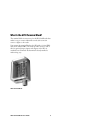
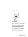
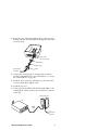
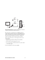
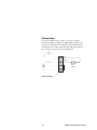
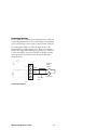
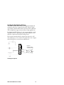
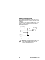
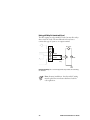
User's Guide
GPIO Terminal
Block
Intermec Technologies Corporation
Corporate Headquarters
6001 36th Ave. W.
Everett, WA 98203
U.S.A.
www.intermec.com
The information contained herein is proprietary and is provided solely
for the purpose of allowing customers to operate and service Intermecmanufactured equipment and is not to be released, reproduced, or used
for any other purpose without written permission of Intermec.
Information and specifications contained in this document are subject
to change without prior notice and do not represent a commitment on
the part of Intermec Technologies Corporation.
© 2005 Intermec Technologies Corporation. All rights reserved.
The word Intermec, the Intermec logo, Norand, ArciTech, CrossBar,
Data Collection Browser, dcBrowser, Duratherm, EasyADC,
EasyCoder, EasyLAN, Enterprise Wireless LAN, EZBuilder,
Fingerprint, i-gistics, INCA (under license), Intellitag, InterDriver,
Intermec Printer Network Manager, IRL, JANUS, LabelShop, Mobile
Framework, MobileLAN, Nor*Ware, Pen*Key, Precision Print,
PrintSet, RoutePower, SmartSystems, TE 2000, Trakker Antares, and
Virtual Wedge are either trademarks or registered trademarks of
Intermec Technologies Corporation.
Throughout this manual, trademarked names may be used. Rather
than put a trademark (™ or ®) symbol in every occurrence of a
trademarked name, we state that we are using the names only in an
editorial fashion, and to the benefit of the trademark owner, with no
intention of infringement.
There are U.S. and foreign patents pending.
ii
GPIO Terminal Block User’s Guide
Contents
What Is the GPIO Terminal Block?............................................ 5
About the Terminal Block Connections............................... 6
About the Input, Output, and Power Terminal
Connections ................................................................... 6
Installing the Terminal Block...................................................... 7
Installing the Terminal Block...................................................... 8
Using the Terminal Block ......................................................... 10
About the IF5 GPIO Interface........................................... 10
Connecting Devices to the Input Terminals....................... 10
IF5 Powered Input ..................................................... 12
Isolated Input Interface............................................... 13
Open Collector Input Interface .................................. 14
Connecting Devices to the Output Terminals.................... 15
Switching the High Side Using IF5 Power.................. 17
Switching the Low Side Using IF5 Power ................... 18
Switching the High Side Using External Power .......... 19
Driving a DC Relay To Control an AC Load ............. 20
Connecting Devices to the Power Terminal ....................... 21
Sample System Diagram ........................................................... 22
Where to Go From Here .......................................................... 23
Specifications ............................................................................ 23
Serial Port Pinouts ............................................................. 23
GPIO Terminal Block User’s Guide
iii
iv
GPIO Terminal Block User’s Guide
What Is the GPIO Terminal Block?
The terminal block is an accessory for the IF5 Fixed Reader that
makes it easy to connect industrial controls such as motion
sensors or lights to the reader.
You connect the terminal block to the IF5 with a 25-pin GPIO
cable (P/N 236-057-001). The block provides access to each of
the four general purpose inputs and outputs on the IF5 via
standard screw terminals. Each terminal is clearly marked to
make wiring easy.
GPIO Terminal Block
GPIO Terminal Block User’s Guide
5
About the Terminal Block Connections
The terminal block has a serial port and a strain relief connector
as shown in the next illustration.
Serial port
Strain relief
connector body
Bushing
Split ring
Sleeve
Terminal Block Connections
To connect the terminal block to an IF5, you need a 25-pin
GPIO cable (P/N 236-057-001). You supply your own cables or
wiring for your industrial controls.
For more information on connecting industrial controls to the
terminal block, see “Using the Terminal Block” on page 10.
About the Input, Output, and Power Terminal
Connections
The terminal block provides standard screw terminals that you
use to connect industrial control wiring to the IF5 GPIO and
power interfaces.
The screw terminals are located inside the terminal block on the
main circuit board and are arranged as shown in the next
illustration.
6
GPIO Terminal Block User’s Guide
Inputs
+12V
+
Ground
Outputs
+12V
4
Ground
+12V
+
Ground
3
2
Ground
+
-
Ground
+12V
+
-
Ground
+12V
+12V
+
-
Ground
+12V
+12V
+
-
+
-
1
+
-
Ground
+12VDC
Power
Ground
Terminal Connections: This illustration shows the input, output, and power
terminal connections on the main circuit board.
GPIO Terminal Block User’s Guide
7
Installing the Terminal Block
Note: For IP54 compatibility, mount the terminal
block with the connector side facing toward the floor.
You need these tools to install the terminal block:
• Drill and drill bits appropriate for the mounting surface
• Small straight-slot and Phillips screwdrivers
• Wire crimping and stripping tool
Note: The terminal block includes four #6 x 2 in
wood screws you can use for mounting, or you can
supply your own mounting hardware.
To install the terminal block
1 Choose a location for the terminal block.
2 Drill four mounting holes. Use the included drilling template
(P/N 931-008-001).
3 Remove the top cover from the terminal block.
4 Place the terminal block in the location and secure it to the
mounting surface with four appropriate fasteners.
Mounting
hardware
(4 places)
8
GPIO Terminal Block User’s Guide
5 Route the control wiring through the sleeve, split ring, and
bushing, and into the terminal block through the strain relief
connector body.
Strain relief
connector body
Bushing
Split ring
To industrial
controls
Sleeve
6 Connect the control wiring to the appropriate terminals
inside the terminal block. For more information, see “Using
the Terminal Block” on page 10.
7 Install the sleeve, split ring, and bushing on the strain relief
connector body (finger tighten only).
8 Install the top cover.
9 Connect the 25-pin GPIO cable (P/N 236-057-001) to the
terminal block serial port and to the Control Port connector
on the IF5.
Terminal block
IF5
GPIO
cable
To
industrial
controls
GPIO Terminal Block User’s Guide
9
Using the Terminal Block
This section explains how the terminal block connects to the IF5
GPIO interface and how you connect devices to the terminal
block input, output, and power terminals.
About the IF5 GPIO Interface
The IF5 reader has four general purpose input and output
interfaces. Each interface is electrically isolated from the IF5 and
designed for low voltage DC loads. The IF5 can also supply
12VDC at 0.5A to external devices.
The GPIO Terminal Block provides convenient access to these
interfaces through its input, output, and power terminals. You
use a standard 25-pin serial cable to connect the terminal block
to the Control Port connector on the IF5.
Connecting Devices to the Input Terminals
Each input terminal has four terminal posts:
• +12V
• +Input
• -Input
• Gnd (Ground)
The input terminals allow you to access the four general purpose
inputs on the IF5. Each of the four inputs is compatible with
input signals of 10 to 48 VDC. Each input terminal includes a
green indicator LED that lights up when the input circuit is
energized, giving visual feedback to users.
10
GPIO Terminal Block User’s Guide
12VDC
- +
Reader
Interface
Internal
1.8KΩ
+12V
+Input
-Input
Ground
Input Terminal Schematic: This illustration shows an input terminal. The
- Input post is shorted to the Ground post by a jumper.
How the inputs are used depends on the RFID application
software being used in the system. In a typical application, the
reader senses input from an external control like a switch and
then starts a tag read operation. You need to coordinate the
wiring of any input controls with the software developer.
There are three basic ways to connect input controls to the
terminal block:
• Supply the input interface with power from the IF5.
• Isolate the IF5 from the input power source.
• Use an open collector solid-state drive from a remote device
to control the inputs.
For more information, see the next examples.
GPIO Terminal Block User’s Guide
11
IF5 Powered Input
This is the simplest way to connect a control to an input
terminal. Each input terminal is supplied with a jumper wire
between the -Input and Ground posts. If the input device is a
switch closure, you can connect the other side of the switch to
the +12V post as shown in the next illustration.
+12V
+Input
External
input
switch
IF5 Powered Input
12
GPIO Terminal Block User’s Guide
Isolated Input Interface
Use this method to minimize noise induced because of distance
or grounding characteristics. The isolated input avoids induced
noise by referencing a remote input to chassis return of the IF5.
Use a twisted pair cable to connect the input device to the
terminal block to further suppress noise. Remove the jumper
between the -Input and Ground posts so there is no connection
to either the 12VDC power from the IF5 or the IF5 reference
chassis ground. The next illustration shows how this input
method is wired.
External
input
switch
+Input
-Input
- +
10-48 VDC
Twisted
pair
Isolated Input Interface
GPIO Terminal Block User’s Guide
13
Open Collector Input Interface
The input can be connected to an open collector interface of an
external device. This typically implies that the grounds are tied
together for the two systems. The common ground can be a
source of input noise, so you should follow good grounding
practices for both the IF5 and the input device.
The illustration shows the IF5 providing power to the pull up
resistor for the open collector. Remove the jumper between the
-Input and Ground posts, and use it to short out the +12V and
+Input posts.
Input
Ground
Open Collector Input Interface
14
GPIO Terminal Block User’s Guide
Connecting Devices to the Output Terminals
Each output terminal has four terminal posts:
• +12V
• +Output
• -Output
• Gnd (Ground)
The output terminals allow you to access the four general
purpose outputs on the IF5. Each IF5 output is optically
isolated from the IF5, polarized, and rated for 5 to 48 VDC at
0.25A. All IF5 outputs include internal thermal fuses that trip if
the load exceeds 0.25A, and the fuses are self-recovering once
the excessive load is removed.
12VDC
- +
Reader
Interface
+12V
+Output
-Output
Indicator
LED
Ground
Output Terminal Schematic: This illustration shows an output terminal. The
+Output and +12V posts are shorted by a jumper.
Each terminal block output terminal includes a green indicator
LED that can be enabled or disabled depending on system
requirements.
GPIO Terminal Block User’s Guide
15
How the outputs are used depends on the RFID application
software being used in the system. For example, the outputs can
control indicator lamps that indicate good reads or errors. You
need to coordinate the wiring of any output controls with the
software developer.
Because the outputs are optically isolated, each one can be
configured to switch the high side or the low side of the load.
You can power the load directly from the IF5 or from an
external power supply.
The next examples illustrate several ways to connect controls to
the output terminals:
• Switching the high side, with the load powered by the IF5
• Switching the low side, with the load powered by the IF5
• Switching the high side, with the load powered externally
• Driving a DC relay that controls an AC load
16
GPIO Terminal Block User’s Guide
Switching the High Side Using IF5 Power
The GPIO Terminal Block is factory configured for high side
switching, with power coming from the IF5. Only the single
output being switched will be affected if the interface cable fails.
This configuration supports many indicator lamp applications.
By default, the LED indicator for each output terminal is wired
in parallel with the output load, giving visual feedback to users
when the output from the IF5 has changed state.
Each output terminal includes a jumper that shorts the +12V
and +Output posts. You connect the output load to the -Output
and Ground posts as seen in the next illustration.
External
indicator lamp
0.25A maximum
Input
Ground
Switching the High Side
GPIO Terminal Block User’s Guide
17
Switching the Low Side Using IF5 Power
For low side switching applications, the lamp power is routed to
all the lamps in common and the low side of the load is routed
to the switch.
To configure an output terminal for low side switching, use the
jumper to short the -Output and Ground posts together as
shown in the next illustration.
+12V
External
indicator lamp
0.25A maximum
+Output
Switching the Low Side of the Output Load
Note: In this configuration the indicator LED for the
output terminal is disabled and may create some
confusion with maintenance activity.
18
GPIO Terminal Block User’s Guide
Switching the High Side Using External Power
To switch the high side of a load that uses external power, you
need to remove the output terminal jumper. You should also
connect the IF5 ground to the ground system of the external
power supply, which enables the output terminal LED (not
shown in the illustration). When the output is turned on, the
LED lights up.
Connect the external power source as shown in the next
illustration.
+ External
power
5-48 VDC
+Output
-Output
Ground
External
indicator
lamp
Switching the High Side With External Power
Note: If the IF5 ground is not connected to the
external power ground, the output terminal LED will
behave unpredictably, but will light up if there is a
sneak path in the chassis ground.
GPIO Terminal Block User’s Guide
19
Driving a DC Relay To Control an AC Load
The IF5 outputs can only switch DC loads, but can drive relays
that control AC loads. The next illustration shows how to
connect this type of system to an output terminal.
AC motor
-Output
120-230
VAC
Ground
External
relay
Driving a DC Relay: The external relay provides dry contacts for controlling
the AC motor.
Note: In many installations, the relay and AC wiring
must be placed in an enclosure that meets local fire
code regulations.
20
GPIO Terminal Block User’s Guide
Connecting Devices to the Power Terminal
The power terminal provides access to DC power from the IF5.
The GPIO interface provides 12VDC at 0.5A for powering
external inputs and loads, eliminating the need for an external
DC supply and simplifying the system installation.
The GPIO interface power has an internal thermal fuse that
trips if the load exceeds 0.5A, and the fuse is self-recovering once
the excessive load is removed.
The total load on the GPIO interface power must stay within
the 0.5A limit. When you design a system that uses this supply,
be sure to complete a power budget assessment to ensure that
the supply is adequate for the system.
On the power terminal, two posts are available for +12VDC and
Ground. These posts are tied to each of the +12V and Ground
posts on the input and output terminals.
If your system needs more than +12VDC at 0.5A, you can
connect an external power supply to the +12V and Ground
posts on the power terminal. The external supply will power the
external loads, and that power will be available at all +12V posts
on the input and output terminals.
GPIO Terminal Block User’s Guide
21
Sample System Diagram
This illustration shows how to connect a system that uses
position detection sensors as inputs and indicator lamps as
outputs. All are connected to the power terminal on the terminal
block and powered by the IF5.
Outputs
Inputs
Position
detection
sensor
Position
detection
sensor
Output #2
indicator
lamp
+12V
+Input
-Output
Ground
Output #1
indicator
lamp
+12V
+Input
-Output
Ground
+12VDC
Ground
22
GPIO Terminal Block User’s Guide
Where to Go From Here
For information on configuring and operating the IF5, see the
IF5 Fixed Reader User’s Manual (P/N 074747).
You may need additional information when working with the
IF5 in your data collection system. Please visit
www.intermec.com to download PDF files of our current
manuals. To order printed versions of Intermec manuals,
contact your local Intermec representative or distributor.
Specifications
Dimensions:
17.4 cm (6.88 in) x 12.4 cm (4.88 in) x
7.4 cm (2.94 in)
Weight:
510 gm (1.12 lbs)
Input terminal ratings:
10 to 48 VDC
Output terminal ratings:
5 to 48 VDC @0.25A
Power terminal ratings:
+12 VDC @0.5A
Serial interface:
DB25 (P/N 236-057-001)
Operating environment:
Temperature:
-25°C to 70°C (-13°F to 158°F)
Humidity:
10 to 90%, non-condensing
Environmental rating:
IP54. Terminal block must be mounted
with the connector side facing down.
Serial Port Pinouts
Pin 1
Pin 14
GPIO Terminal Block User’s Guide
Pin 13
Pin 25
23
6001 36th Avenue West
Everett, Washington 98203
U.S.A.
tel 425.348.2600
fax 425.355.9551
www.intermec.com
© 2005 Intermec Technologies
Corporation. All rights reserved.
GPIO Terminal Block User’s Guide
*934-001-001*
P/N 934-001-001 Rev A