1
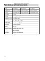
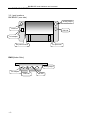
BW/BWS-E series
Indicator Scales
User’s guide
BW/BWSE v1.03
BW/BWS-E serial Indicator user’s manual
Table of Contents
SECTION 1 INTRODUCTION…………………………………………………….………1
SECTION 2 SPECIFICATIONS………………………………………………….…..……2
SECTION 3 INSTALLATION……………………………………………………………….3
3. 1 General installation…………………………………………………………….………3
3. 2 Installation of BW/BWS-E series…………………………………………….3
3. 3 Port connect……………………………………………………………….……………4
3.3.1 Port location……………………………………………………………….…………..4
3.3.2 Load cell port…………………………………………………………….….…………5
3.3.3 RS-232…………………………………………………………………………………5
3.3.4 Analog output and check weighing output………………………………………….5
3.3.5 Mercury level bubble…………………………………………………………………6
SECTION 4 KEY DESCRIPTIONS………………………………………….……………7
SECTION 5 DISPLAYS…………………………………………………………………….8
SECTION 6 OPERATION…………………….……………………………….……….…..9
6.1 Zeroing the display…………………………………………………………….……….9
6.2 Taring……………………………………………………………………………....…….9
6.3 Weighing a sample…….………………………………………………….…………….9
6.4 Check-weighing………………………………………………………………………….9
6.4.1 About check weighing……………………………………………..………………….9
6.4.2 Set limit………………………………………………………………..……………10
6.4.3 Set check weighing mode…………………………………………………………10
6.4.4 Note………………………………………………………………………….………..10
6.5 Accumulated total……………………………………………………………………10
6.5.1Note……………………………………………………………………………………10
6.5.2 Accumulate operate………………………………………………………..………10
6.5.3 Memory recall……………………………………………………………..…………11
6.5.4 Memory clear……………………………………………………………..…………11
6.5.5 Automatically accumulate…………………………………………………………..11
6.6 animal …………………………………………………………………………….11
6.7 keyboard lock…………………………………………………………………………..11
6.8 set auto power off ……………………………………………………………………..11
SECTION 7 PARAMETERS………………………………………………………………12
SECTION 8 BATTERY OPERATION…………………………………………..……..…16
SECTION 9 RS-232 OUTPUT…………………………………………………..………..17
9.1 basic information……………………………………………………………….………17
9.2 normal output……………………………………………………………………..……17
9.3 continuously output protocol…………………………………………………….……17
SECTION 10 CALIBRATION……………………………………..……………….……..18
SECTION 11 ERROR CODE…………………………………….………………………20
-I-
BW/BWS-E serial Indicator user’s manual
SECTION 1 INTRODUCTION
The BW/BWS-E series of indicator provides an accurate, fast and versatile series of
general purpose weighing scale with counting and check-weighing functions.
There are 3 series s within the range, the platform size from 350mm x 450mm to
600mm x 800mm, the capacity range from 30kg to 1000kg
All the displays are large easy to read liquid crystal type displays (LED)
All units include automatic zero tracking, audible alarm for pre-set weights, and an
accumulation facility that allows the individual weights to be stored and recalled as
an accumulated total.
-1-
BW/BWS-E serial Indicator user’s manual
SECTION 2 SPECIFICATIONS
Model
SBW/BWS-E
MBW/BWS-E
LBW/BWS-E
Platform size
350mm x 450mm
420mm x 520mm
600mm x 800mm
Capacity
30kg/60kg/150kg
60kg/150kg/300kg
300kg/600kg/1000kg
Resolution
1:15.000
Interface
RS-232 Output Optional
Analog Output Optional
Stabilisation Time
1 Seconds typical
Operating
Temperature
0°C - 40°C / 32°F - 104°F
Power supply
External AC adapter, 9V 800mA
AC powered, 115V/230V
Calibration
Automatic External
Display
1.2’’ LED
Balance Housing
Indicator ABS Plastic / SST
Load cell drive
voltage
Max 5V/150mA
Load cells
Up to four 350 ohms cells
-2-
BW/BWS-E serial Indicator user’s manual
SECTION 3 INSTALLATION
3. 1 GENERAL INSTALLATION
The s should be sited in a location that will not degrade the accuracy.
Avoid extremes of temperature. Do not place in direct sunlight or near air
conditioning vents.
Avoid unsuitable tables. The tables or floor must be rigid and not vibrate. Do not
place near vibrating machinery.
Avoid unstable power sources. Do not use near large users of electricity such as
welding equipment or large motors.
Avoid high humidity that might cause condensation. Avoid direct contact with water.
Do not spray or immerse the s in water.
Avoid air movement such as from fans or opening doors. Do not place near open
windows.
Keep the s clean.
Do not stack material on the s when they are not in use.
3. 2 INSTALLATION OF BW/BWS-E SERIES
The pillar is attached to the base using a bracket that must first be attached to the
base frame using the 4 bolts supplied. The Pillar is secured to the bracket using 2
set screws. The cable from the base to the indicator module is run through the tube,
out through the plastic support at the top. Excess cable can be stored within the
tube.
The BW/BWS-E Series comes with a stainless steel platform packed separately.
Place the platform in the base.
Level the scale by adjusting the four feet. The scale should be adjusted such that the
bubble in the spirit level is in the center of the level and the scale is supported by all
four feet. If the scale rocks read just the feet.
Attach the indicator module to the pillar by sliding it over the bracket with the flanges
engaged in the groves on the base.
Attach the cable from the base to the
connector on the rear of the indicator.
Attach the AC power adapter to the connector on the back of the indicator.
-3-
BW/BWS-E serial Indicator user’s manual
3. 3 PORT CONNECTION
3.3.1 port locations
BW/BWS-E (rear side)
Analog output
Load cell
RS-232
AC adapter
AC power socket
For pole neck
BWS (Under Side)
Analog output
AC adapter
Load cell
-4-
RS-232
BW/BWS-E serial Indicator user’s manual
3.3.2 load cell port
Load cell connect as below( 5pin air connecter)
EXC+
SEN+
SIG+
LOAD CELL
5
5
3
2
4
4
1
SIG-
SENSHIELD
EXC-
3.3.3 RS-232
RS-232 (Air connector / D type connector)
2
RXD
Input
Receiving data
3
TXD
Output
Transmission data
5
GND
―
Signal ground
3.3.4 Analog output and check weighing output
9 pin air connector
pin1~pin6: check weighing output
pin 1 hi (output)
pin 2 ok (output)
pin 3 low (output)
pin 4 beep (output)
pin 5 vcc (5V)(output)
pin 6 com (gnd)
-5-
BW/BWS-E serial Indicator user’s manual
pin6~pin9 analog output
pin 6 com (gnd)
pin 7 analog power input (10~32VDC, +) (input)
pin 8 T+ (0~10V/4~20mA) (output)
pin9 T- (0~10V/4~20mA) (output)
Check weighing output application sample (you need a additional output control
PCBA)
BW/BWS-E
indicator
Output control PCBA
J1
AC power
L
N
3.3.5 Mercury level bubble
If you want to scale can’t work when not level, you can add one mercury level bubble,
connect 2 wire to K1, when scale not level, mercury level bubble short, indicator will
show “err l”, when this message appear, please adjust scale level.
If you don’t need this function, just leave K1 unused.
-6-
BW/BWS-E serial Indicator user’s manual
SECTION 4 KEY DESCRIPTIONS
ON/ OFF or
Turn on or off the power.
Zero
Set the zero point for all subsequent weighing. The display shows zero.
A secondary function of "Enter" key when set parameters or other functions.
Tare
Stores the current weight in memory as a tare value, subtracts the tare value from
the weight and shows the results.
A secondary function incrementing the active digit when set a value for parameters
or other functions.
Press Zero and Tare key together in normal weighing mode will turn on/off animal
function. (When enter/escape animal mode, you will hear beeper on twice)
MR
Memory recall key, show total accumulate weight in memory.
In setting mode, this key used to move active digits right.
M+
Accumulate key, store current weight in memory.
In setting mode, this key used to move active digits left.
Press M+ and MR key for MC (memory clear)
Print
For print the results to a PC or printer using the optional RS-232 interface.
Press Print during self checking will enter setting mode.
G/N
Gross weight/net weight shift key, Hold this key for 3 seconds to shift the unit.
Secondary function (ESC) , is to return to normal operation when the mode is in a
parameter setting mode.
Press G/N and Print key together for setting check Weighing limit.
-7-
BW/BWS-E serial Indicator user’s manual
SECTION 5 DISPLAYS
The LED display will show a value. In addition there are LED lights for Zero, Stable,
Tare, Batt, Kg, U2.
-8-
BW/BWS-E serial Indicator user’s manual
SECTION 6 OPERATION
6.1 Zeroing The Display
You can press the ZERO key at any time to set the zero point from which all other
weighing and counting is measured, within 4% of power up zero. This will usually
only be necessary when the platform is empty. When the zero point is obtained the
display will show the indicator for zero.
The scale has an automatic rezeroing function to account for minor drifting or
accumulation of material on the platform. However you may need to press the ZERO
key to rezero the scale if small amounts of weight are shown when the platform is
empty.
6.2 Taring
Zero the scale by pressing the ZERO key if necessary. The zero indication will be on.
Place a container on the platform, a value for its weight will be displayed.
Press the TARE key to tare the scale. The weight that was displayed is stored as the
tare value and that value is subtracted from the display, leaving zero on the display.
The "NET" indicator will be on. As product is added only the weight of the product will
be shown. The scale could be tared a second time if another type of product was to
be added to the first one. Again only the weight that is added after taring will be
displayed.
When the container is removed a negative value will be shown. If the scale was tared
just before removing the container this value is the gross weight of the container plus
all product that was removed. The zero indicator will also be on because the platform
is back to the same condition it was when the ZERO key was last pressed.
6.3 Weighing a sample
To determine the weight of a sample first tare the empty container then place the
sample in the container. the display will show the weight and the units of weight
currently in use.
6.4 Check-Weighing
6.4.1 About check-weighing
Check-weighing is a procedure to cause an alarm to sound when the weight on the
meets or exceeds values stored in memory. The memory holds values for a high
limit and a low limit.
-9-
BW/BWS-E serial Indicator user’s manual
Check mode OK:
When check range, the display will show OK and the beeper will sound when the
weight is between the limits.
Check mode NG:
When check range, the display will show OK and the beeper will sound when the
weight is out of the limits.
6.4.2 Set limits
Press G/N and PRINT key together, it will display “set h”, use TARE key to select
“SET H” or “SET L”, press ZERO key to enter, use M+ and MR key to move active
digit, use TARE key to change value, use Print key to clear value. After you enter
the value, press ZERO key to sure, press G/N key to escape.
6.4.3 Set check weighing mode
Press G/N and print key together, it will display “set h”, use TARE key to select
beep, press ZERO key to enter, press TARE key to select ok(check mode OK), ng
(check mode NG), no(no beep), press ZERO key to sure, press G/N key to escape.
6.4.4 NOTE
Check weighing function only available when weight more than 20d (min).
To disable the Check-Weighing function enter zero into both limits by pressing the
PRINT key when the current limits are shown then pressing ZERO/ENTER to store
the zero values.
6.5 Accumulated Total
6.5.1 Note
The scale can be set to accumulate manually by pressing the M+ key. See the
PARAMETERS Section for details of selecting the method using function "P2 com".
Please note before every accumulate operate, scale need return to zero, and only
press M+ key when stable, when weight less than 20d, accumulate operate will be
invalid.
6.5.2 Accumulate operate
The weight displayed will be stored in memory when the M+ key is pressed and the
weight is stable.
The display will show "ACC 1" and then the total in memory for 2 seconds before
returning to normal. (after do accumulate operate, “M+” indicator will turn on) If the
optional RS-232 interface is installed the weight will be output to a printer or PC.
Remove the weight, allowing the scale to return to zero and put a second weight on.
Press the M+ key, the display will show "ACC
2" and then the new total.
- 10 -
BW/BWS-E serial Indicator user’s manual
Continue until all weights have been added.
6.5.3 memory recall
To view the totals in memory press MR key.
6.5.4 memory clear
To clear the memory, just press M+ and MR together
6.5.5 automatically accumulate
Press Print key during self checking, enter setting mode, press Tare key until display
show P32COM, press ZERO key to enter, press TARE key to select “mode”, press
ZERO key to sure, display will show current RS-232 mode, press TARE key to select
Auto. After you set, AUTO indicator on.
Press weight on platform, after stable, you will hear beep on twice, you can add or
remote weight now, scale will beep on again after stable, at last, remove all weight
on platform, the last weight value will store in memory
6.6 Animal s
Let the animal on the platform, after some second, if reading data change not a lot,
you can hear beep sound and reading data will be locked.
In reading data lock mode, if you add/remove big weight, display will still update and
lock new reading data.
You can press ZERO TARE together to enter/escape animal weighing mode.
6.7 Keyboard lock
You can use keyboard lock when this function enable (see detail setting process in
section 7), after keyboard haven’t use for 10 minutes, keyboard will be lock, after
enter lock status, if you press any key, display will show “K-LCK”.
If you want to escape lock mode and return work mode, hold PRINT , MR , ZERO
key 2 seconds, display will show “ULCK”, return normal mode.
6.8 set auto power off
Hold ZERO key 3 second, display will show ”setbl “, press ZERO key to enter.
press TARE key, display show “setoff”, press ZERO key to enter auto power off
setting, press TARE key to change auto power off time:0ff/on/3/5/15/30. (of ON:
always on, of off: always off, of xx: auto power off after standby xx minutes),
press ZERO key to sure, press G/N key to escape.
- 11 -
BW/BWS-E serial Indicator user’s manual
SECTION 7 PARAMETERS
The scale has 5 parameters that can be set by the user plus a method of entering
the calibration section.
To set parameters press the PRINT key during self checking, display will show pn
(ask password), press M+, G/N, TARE to enter.
The display will show the first function, "p0 chk".
Pressing the TARE key will cycle through the other functions.
Pressing ZERO will allow you to set the function. It may be necessary to either use
TARE or set a value using the M+ MR key to move the active digit and then using
the TARE key to increment a digit, followed by the ZERO key to enter the value. Use
the G/N key to leave a parameter unchanged.
For example when the display shows “p0 chk” press the ZERO key to begin.
The display will show “Set Lo”, press the ZERO key to set the low limit, or press the
TARE to skip to the next parameter, “Set Hi” for setting the high limit.
After pressing the ZERO key to set a limit, use the M+ MR keys to change the
flashing digit, then use the TARE key to increment the flashing digit. Continue to
the next digit and set it as needed.
When all digits have been set press the ZERO key to store the value. The display
will go back to the parameter just set, i.e. “Set Lo”. Advance to another parameter if
needed or press the G/N key to return to weighing.
Parameter setting table
functio
n
P0
CHK
Sub function
SET H
SET LO
BEEP
P1
REF
AZN 0
0AUTO
- 12 -
describe
Set high limit, press M+ MR key to move active digit, press
TARE to change value, press PRINT key to clear data,
press ZERO key to sure.
Set high limit, press M+ MR key to move active digit, press
TARE to change value, press PRINT key to clear data,
press ZERO key to sure.
Set beep mode,
no: no beep for check Weighing
OK: beep when weight between hi and low (OK)
ng: beep when weight out of hi-low range (NG)
This option is used to select the auto zero tracking range
Options : 0.5d, 1d, 2d, 4d
This option is used to select the auto zero range when turn
the indicator.
Options : 0%, 2%, 5%, 10%, 20%, 50%, 100%
BW/BWS-E serial Indicator user’s manual
0RAGE
This option is used to select the manual zero range when
press the ZERO key.
Options: 0%, 2%, 4%, 10%, 20%, 50%, 100%
This option is used to set whether Bench Scales will do
auto zero tracking in net mode (after do tare operate, net
weight is zero) Options: ON/OFF
Set the ADC speed
7.5/15/30/60 times/second
Set new zero point, after set this value, when in zero point,
the reading will be –xxx.xxx
This option is used to set RS-232 communication mode
Options:
CONT(continuously send)
ST1: send one frame data after stable
STC: send data continuously when stable
PR1: when press print key, send one frame data (printer
mode)
PR2: when press M+ key, do print data and M+ at the
same time
AUTO: auto accumulate (auto print) mode, when weight
stable and then return to zero, indicator will do accumulate
and print operate automatically
ASK: ask mode, bi-direction,
Command R: read data
Command T: tare
Command Z: zero
Wireless: wireless mode
Note: if you have selected the wireless model, the
communication mode has to be set to wireless.
This option is used to set baud rate
Options: 600/1200/2400/4800/9600
This option is used to set parity verify
Optional: 7E1/7O1/8N1
0-TARE
SPEED
ZERO
P2
COM
MODE
BAUD
pr
ptype
P3
Lin
lab
tpup: set the printer as tpup model.
lp-50: set the printer as LP-50 model.
“Lab x”, set gross/acc print format
prt
“prt, set the date/time print format
DECI
This option is used to select the decimal
Options : 0, 0.0, 0.00, 0.000
This option is used to select the division
Options : 1, 2, 5, 10, 20, 50, 100, 200
This display will show xxxxxx for setting the capacity.
Nonlin
Non- linearity Calibrate
Liner
Linearity Calibrate
This display will show xxxxxx for indicating the internal
counts.
Enable /disable key lock
Dual
ON/ OFF
INC
CAP
CAL
COUNT
P4
LOCK
- 13 -
BW/BWS-E serial Indicator user’s manual
OTH
ANM
P5
unt
Kg/ Lb/ L2/ tj/
hj
P6
Cal
ON (animal )
OFF(normal mode)
Set unit, when the unit is set for U2, then this unit could be
active to U2. Note: lb, oz, Tj and Hj could not be used at
the same time. If you select U2, then will get kg and which
you select secondary unit.
External calibration.
Form one
LAB
TYPE
1
2
3
tpup
tpup
tpup
GS: 0.888kg
NT:
0.666kg
TW: 0.222kg
GW: 0.888kg
GS:
0.222kg
TOTAL: 0.222kg
1
DATE: 04/06/06
GS:
0.888kg
DATE: 04/06/06
NT:
0.666kg
TW: 0.222Kg
GW: 0.888kg
DATE: 04/06/06
GS:
0.222kg
TOTAL: 0.444kg
2
TIME: 11/11/11
GS:
0.888kg
TIME: 11/11/11
NT:
0.666kg
TW: 0.222kg
GW: 0.888kg
TIME: 11/11/11
GS:
0.222kg
TOTAL: 0.666kg
3
DATE: 04/06/06
TIME: 11/11/11
GS:
0.888kg
DATE: 04/06/06
TIME: 11/11/11
NT:
0.666kg
TW: 0.222kg
GW: 0.888kg
DATE: 04/06/06
TIME: 11/11/11
GS:
0.222kg
TOTAL: 0.888kg
4
NO.:
GS:
NO. : 4
NT :
0.666kg
TW:
0.222kg
GW:
0.888kg
NO.:
4
GS:
0.222kg
TOTAL: 1.000kg
5
DATE: 04/06/06
NO.: 5
GS:
0.888kg
DATE: 04/06/06
NO.:
5
NT:
0.666kg
TW:
0.222kg
GW:
0.888kg
DATE: 04/06/06
NO.:
5
GS:
0.222kg
TOTAL: 1.222kg
6
TIME: 11/11/11
NO.: 6
GS:
0.888kg
TIME:
NO.:
NT:
TW:
GW:
TIME:
11/11/11
NO.:
6
GS:
0.222kg
TOTAL: 1.444kg
DATE: 04/06/06
TIME: 11/11/11
NO.: 7
GS:
0.888kg
DATE: 04/06/06
TIME: 11/11/11
NO.: 7
NT:
0.666kg
TW: 0.222kg
GW: 0.888kg
NT:
0.222kg
TW:
0.666kg
GW:
0.888kg
TOTAL: 0.222kg
DATE: 04/06/06
NT:
0.222kg
TW:
0.666kg
GW:
0.888kg
TOTAL: 0.444kg
TIME: 11/11/11
NT:
0.222kg
TW:
0.666kg
GW:
0.888kg
TOTAL: 0.666kg
DATE: 04/06/06
TIME:
11/11/11
NT:
0.222kg
TW:
0.666kg
GW:
0.888kg
TOTAL: 0.888kg
No.:
4
NT:
0.222kg
TW:
0.666kg
GW:
0.888kg
TOTAL: 1.000kg
DATE: 04/06/06
No.:
5
NT:
0.222kg
TW:
0.666kg
GW:
0.888kg
TOTAL: 1.222kg
TIME: 11/11/11
No.:
6
NT:
0.222kg
TW:
0.666kg
GW:
0.888kg
TOTAL: 1.444kg
DATE: 04/06/06
TIME: 11/11/11
No.:
7
NT:
0.222kg
TW::
0.666kg
GW:
0.888kg
TOTAL: 1.666kg
PRT
0
7
- 14 -
0
tpup
4
0.888kg
11/11/11
6
0.666kg
0.222kg
0.888kg
DATE:
TIME:
NO.:
GS:
TOTAL:
04/06/06
11/11/11
7
0.222kg
1.666kg
BW/BWS-E serial Indicator user’s manual
Form two
LAB
PRT TYPE
0
1
2
3
4
5
6
7
0
LP-50
2000/00/00 00:00
S/N
1
GW
0.888kg
DATE: 2000/00/00
TIME: 00:00
GW: 0.888kg
DATE:
TIME:
00:00
S./NO.:
2
GROSS WT: 0.888kg
2000/00/00 00:00
S/N
0003
GW
0.888kg
2000/00/00 00:00
S/N
4
GW
0.888kg
DATE: 2000/00/00
TIME:
00:00
GW:
0.888kg
DATE:
TIME:
00:00
S./NO.:
6
GROSS WT: 0.888kg
2000/00/00 00:00
S/N
7
GW
0.888kg
1
2
3
LP-50
left
As
left
As
LP-50
left
As
left
As
left
As
left
As
left
As
left
As
left
As
left
As
left
As
left
As
left
As
left
As
left
As
left
As
left
As
left
As
left
As
left
As
left
As
left
As
left
As
left
As
LP-50
- 15 -
BW/BWS-E serial Indicator user’s manual
SECTION 8 BATTERY OPERATIONS
The indicator can be operated from the battery if desired. The battery life is
approximately 70 hours.
When the battery needs charging a symbol on the weight display will turn on. The
battery should be charged when the symbol is on. The scale will still operate for
about 10 hours after which it will automatically switch off to protect the battery.
To charge the battery simply plug into the mains power. The scale does not need to
be turned on.
The battery should be charged for 12 hours for full capacity.
Just left side of the display is an LED to indicate the status of battery charging.
When the scale is plugged into the mains power the internal battery will be charged.
If the LED is green the battery has a full charge. If it is Red the battery is nearly
discharged and yellow indicates the battery is being charged.
As the battery is used it may fail to hold a full charge. If the battery life becomes
unacceptable then contact your distributor.
- 16 -
BW/BWS-E serial Indicator user’s manual
SECTION 9 RS-232 OUTPUT
The BW/BWS-E Series of s can be ordered with an optional RS-232 output.
9. 1 basic information
Specifications:
RS-232 output of weighing data
ASCII code
7/8 data bits
Parity stable
Baud rate from 600bps to 9600bps
Connector: 9 pin d-subminiature socket / 9 pin air connector
Pin 2: Input,
Pin 3: Output
Pin 5: Signal Ground
9. 2 normal print out
Data Format for normal weighing operations, parts counting or recalling of totals from
memory will all be different. Examples follow:
Normal Output
S/N
GW
The number increments every time a new value is stored in memory
GW for gross weight, NT for net weight and a unit of weight
<If>
<If>
Includes 2 line feeds
When recalling the Total weight stored in the accumulation memory the output format
is:
***************
<lf>
Total No:
3
Total wt.:
0.447KG
***************
A line of stars is shown
Includes 1 line feed
Times of the accumulation memory
Weight of the accumulation memory
9. 3 continuously output protocol
con1: weighing mode
k
-HEADER1--
- HEADER2-
--- WEIGHT DATA --
g
CR LF
-WEIGHT UNIT- TERMINATOR
HEADER1: ST=STABLE US=UNSTABLE
HEADER2: NT=NET GS=GROSS
- 17 -
BW/BWS-E serial Indicator user’s manual
SECTION 10 CALIBRATION
Turn the power off.
Turn the power back on, during the counting from 9 to 0 press the PRINT key.
The display will show "pn " (ask password), press M+, G/N, TARE to enter.
The display will show the first function, "p0chk". , press TARE until display show
P3 Lin, press zero to enter, press Tare to select CAL, press ZERO key to enter
calibrate. The display will show "Nonlin".
1. Normal calibrate
press ZERO key to enter calibrate. The display will show "unLd".
Remove any weight from the platform.
key.
After stable indicator on, press the ZERO
Then the display will show the last calibration weight used. If this is correct you can
continue by pressing the ZERO key. If it is not correct use the M+, MR, TARE
keys to change the calibration weight value. When will correct, press the ZERO
key.
Then display will show "LoAd". Place the calibration weight on the scale. After
stable, press the ZERO key.
2. Linearity Calibrate
Press ZERO key to enter calibrate. Press TARE key. Then the display will show
Liner ".
"
Press ZERO key to enter calibrate. Then the display will show ”PIN”, (ask password),
press G/N, M+ , MR to enter.
The display will show "Load0".
Remove any weight from the platform.
key.
After stable indicator on, press the ZERO
Then the display will show "Load1", apply the reference weight of the full capacity of
the scale just in the center of the platform. The span adjustment will automatically be
achieved.(Calibrate weight request: the front digits if the full capacity. For example,
the full capacity is 300kg, the 30kg/40kg/… to 290kg (integer value) ) will be
accepted. then press the ZERO key.
- 18 -
BW/BWS-E serial Indicator user’s manual
Then the display will show "Load2", apply the reference weight of the full capacity of
the scale just in the center of the platform. The rule is the same as "Load1". then
press the ZERO key.
Then the display will show "Load3", apply the weight of the full capacity, the full
capacity will automatically be achieved. then press the ZERO key.
If the calibration is acceptable the display will return to normal. If an error message
is shown try calibration again as a disturbance may have prevented a successful
calibration.
3. External Calibrate
press TARE until display show P6 Cal, then press ZERO key to enter external
calibrate. The display will show "unLd".
Remove any weight from the platform.
key.
After stable indicator on, press the ZERO
Then the display will show the last calibration weight used. If this is correct you can
continue by pressing the ZERO key. If it is not correct use the M+, MR, TARE
keys to change the calibration weight value. When will correct, press the ZERO
key.
Then display will show "LoAd". Place the calibration weight on the scale. After
stable, press the ZERO key.
Note, only after the linearity calibrate has been completed, then the external calibrate
could be set.
If the problem persists then contact your dealer.
After calibration, it should be checked to verify the calibration and linearity is correct.
If necessary repeat calibration, especially be certain the scale is stable before
accepting any weight.
- 19 -
BW/BWS-E serial Indicator user’s manual
SECTION 11 ERROR CODES
Error Message
----Err 1
Description
Maximum load exceeded
Incorrect date
Err 2
Incorrect time
Err 4
Zero setting error
Err 5
Err 6
Key board error
A/D value out of range
Err 9
Unstable Reading
Err 17
--ol--
Tare out of range
Over range
Fai l h / fai l
l
Err p
Ba lo /
lo ba
Calibration Error
Remove the load and restart scale again.
Remove the load.
Re calibrate
Re calibrate
Printer error
Battery low
Check the printer and settings
Re charge battery, check the voltages.
- 20 -
Solution
Unload or reduce weight
Enter the date by using format
“yy;mm:dd”
Enter the time by using format
“hh:mm:ss”
Zero setting range exceeded due to
switching on.(4%max)
Make sure platform empty.
Check the keys and connecter.
Make sure platform empty and check the
pan is installed proper. Check the load
cell connectors.
Check any air variation, vibration, RF
noise and touching some where.
Check the load cell and connecters.