1
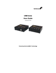
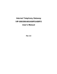
Fiber Optic Extender
for USB
EXT-USB-400FO
USER MANUAL
www.gefen.com
ASKING FOR ASSISTANCE
Technical Support:
Telephone
(818) 772-9100
(800) 545-6900
Fax
(818) 772-9120
Technical Support Hours:
8:00 AM to 5:00 PM Monday thru Friday PST.
Write To:
Gefen, LLC
c/o Customer Service
20600 Nordhoff St.
Chatsworth, CA 91311
[email protected]
www.gefen.com
Notice
Gefen, LLC reserves the right to make changes in the hardware, packaging and any
accompanying documentation without prior written notice.
The USB 400 FO is a trademark of Gefen, LLC
All trademarks are the property of their respective owners.
© 2010 Gefen, LLC, All Rights Reserved
Rev X2
TABLE OF CONTENTS
1
Introduction / Operation Notes
2
Features
3
How It Works
4
USB 400 FO Panel Layout
5
USB 400 FO Series Installation / Check list
6
Wiring Diagram
7
Troubleshooting Hints
8
Troubleshooting Hints
9
System Specifications
10
Warranty
INTRODUCTION
Thank you for purchasing the ex•tend•it USB•400 Series. Incorporating
ExtremeUSB, the new USB•400 model allows users the benefits of USB technology
beyond the desktop, extending your computer keyboard, mouse, trackball, and any USB
device up to 1650 feet away from the location of your Macintosh or PC computer.
The USB•400 system consists of two units: the USB•400S Sender resides next to
the host computer, and the USB•400R Receiver resides next to the extended USB type
device connected by conventional USB cables.
The USB•400 signal controls the keyboard, mouse, trackball and other USB devices
by buffering the keyboard/mouse signal through send and receive line drivers, and the
signal is extended by using standard fiber optic cabling.
The USB•400FO extends any USB device up to 1,650 feet from the location of your
computer, eliminating the 17.5 feet distance limitation of USB. The USB•400FO also
includes a remote 4 port USB HUB to operate up to four USB devices remotely using
“Extreme USB” technology.
OPERATION NOTES
READ THESE NOTES BEFORE INSTALLING
OR OPERATING THE DVI•3000HD SYSTEM
• The USB 400 FO units are housed in a metal box for better RF shielding.
• The USB 400 FO uses two multi-mode LC fiber optic cables fiber optics to connect the
sender and receiver.
• The USB•400 units were designed to operate on USB type computers. DO NOT
attempt to use this equipment with any other type computers.
• Use the computer's USB port when using a local keyboard that is not extended with
the USB•400 sender unit.
• In order to operate properly, the USB•400S and USB•400R units must be connected,
powered up, and the LC fiber optic cable installed between both units.
• The length of cable used to connect the USB•400S send unit to the USB•400R
receiver unit MUST NOT EXCEED 1650 feet.
1
FEATURES
Features
• Extreme USB technology extends the range of USB 2.0 devices up to 1650 meters
(500 meters) using fiber-optic cable
• Remote extender 400FOR is equipped with 4 USB ports
• Provides support for both low-speed and high-speed USB devices
• Comes with a USB cable, power adapters and user guide
• Fully compliant with USB 2.0 specification as certified by the USB Implementers
Forum
• Number of devices can be expanded using standard USB hubs
2
HOW IT WORKS
CONTENTS
The USB 400 FO system consists of:
(1) USB•400FOS Send Unit
(1) USB•400FOR Receive Unit
(1) 6ft A to B USB cable
(2) 5V Power Supply
HOW IT WORKS
The USB•400FO sender unit is connected to the computer using the supplied USB cable.
The extended peripheral(s) are connected to the receiver unit. Two multi mode LC fiber
optic cables are used to link the sender to the receiver with HUB.
3
USB 400 FO PANEL LAYOUT
5V Power
Supply
USB
Inputs for
devices
Link LED
Link LED
Host Port
(USB Type B)
USB Input
LC Input
A
5V Power
Supply
B
Link LED A
B
LC Input
4
USB 400 FO SERIES INSTALLATION
USB•400R (Receiver Unit)
1. Place the USB•400R unit close to the USB device to be served.
2. Connect the USB devices to the USB•400R unit.
3. Connect the power adapter to a suitable AC source wall outlet.
4. Connect the power adapter to the USB•400R unit using the supplied cable.
USB•400S (Sender Unit)
5. Place the USB•400S unit close to the host computer.
6. Connect the power adapter to the USB•400S unit using the supplied cable.
7. Connect the USB•400S unit to the USB•400R unit using the desired length of fiber
optic cable outfitted wit LC connectors with A, on the sender matching B on the
receiver, and B on the sender matching A on the receiver.
8.
Connect the USB•400S unit to the host computer using the 6ft. USB cable supplied
with the unit .
CHECK LIST
1. On the USB•400S send unit, check that the power indicator is GREEN.
2. On the USB•400S send unit, check that the link indicator is GREEN.
3. On the USB•400R receiver unit, check that the power indicator is GREEN.
4. Once all LEDs are illuminated as required, the USB•400 is ready to accept a
peripheral device at the USB port on the USB•400R receiver unit. Follow the
installation instructions as if one were installing the device directly into a computer's
USB port.
5. On the host computer, check that a general purpose hub is visible from the Control
Panel/System applet. Once connected, a USB peripheral device causes its host
computer to automatically enumerate it. This simply means that the computer must
identify the new device, assign it an ID, and ensure that the required software drivers
are available for loading when the device is to be used.
6. The USB•400 is not an end device. Consequently, it does not have a software
component or driver to be loaded. Some peripheral devices that are to be attached
to the USB•400 will have a USB Driver diskette or CD-ROM which will need to be
inserted after initial connection to a USB port on the USB•400 model.
5
WIRING DIAGRAM
6
TROUBLESHOOTING HINTS
Symptoms/Cause
All LEDs on Sender unit are off.
Cause:
The Sender unit is not receiving power
from the adapter
All LEDs on Receiver unit are off.
Cause:
The Receiver unit is not receiving power
from the adapter
Link LEDs on Sender unit and Receiver
unit are off.
Cause:
There is no connection between the
Sender unit and the Receiver unit.
Remedy
1. Ensure that a power adapter is
connected to the Sender unit.
2. Check that the adapter is connected to
a live source of electrical power.
1. Ensure that a power adapter is
connected to the Receiver unit.
2. Check that the adapter is connected to
a live source of electrical power.
1. Ensure that a fiber-optic cable with
crossover is connected between the
Sender unit and the Receiver unit.
2. Connect a short fiber-optic crossover
patch cord between the Sender unit and
the Receiver unit. Recheck the operation
of the system.
Link LED on Sender unit is on;Host LED 1. Disconnect all USB devices from the
Receiver unit.
on Sender unit is off.
2. Disconnect the Sender unit from the
Cause:
computer.
a) The computer is not functioning.
b) The Sender unit is not connected to the 3. Disconnect and then reconnect the
power adapter to the USB 2.0 Ranger.
computer.
4. Reconnect the Sender unit to the
c) The computer does not support USB
computer.
hubs.
d) The USB 2.0 Ranger is malfunctioning. 5. In the Universal Serial Bus controllers
section of Device Manager, check that
the USB 2.0 Ranger is recognized as a
“Generic USB Hub”.
6. If the USB 2.0 Ranger is not
recognised, contact technical support for
assistance.
7
TROUBLESHOOTING HINTS
Symptoms/Cause
A device is connected to the Receiver unit
and the corresponding Device LED is off
Cause:
a) The USB device is malfunctioning.
b) The computer does not recognise the
USB device.
c) The application software for the device
is not operating.
d) The USB 2.0 Ranger is malfunctioning.
Remedy
1. Disconnect the USB 2.0 Ranger from
the computer.
2. Connect the USB device directly to the
USB port on the computer.
3. If the device does not operate properly,
consult the user documentation for the
device.
4. If the device operates properly when
directly connected to the computer,
connect another device (of a different
type) to the USB 2.0 Ranger. Connect
USB 2.0 Ranger to the computer.
5. If the second device does not
operate, the USB 2.0 Ranger may be
malfunctioning. Contact technical support
for assistance.
6. If the second device does operate
properly, the first device may not be
compatible with the USB 2.0 Ranger.
Contact technical support for assistance.
All LEDs on both the Sender unit and
1. Disconnect the USB 2.0 Ranger from
Receiver unit are on but the device does the computer.
not operate correctly
2. Connect the USB device directly to the
Cause:
USB port on the computer.
a) The USB device is malfunctioning.
3. If the device does not operate properly,
b) The computer does not recognise the
consult the user documentation for the
USB device.
device.
c) The application software for the device 4. If the device operates properly when
is not operating.
directly connected to the computer,
d) The USB 2.0 Ranger is malfunctioning. connect another device (of a different
type) to the USB 2.0 Ranger. Connect the
USB 2.0 Ranger to the computer.
5. If the second device does not
operate, the USB 2.0 Ranger may be
malfunctioning. Contact technical support
for assistance.
6. If the second device does operate
properly, the first device may not be
compatible with the USB 2.0 Ranger.
Contact technical support for assistance.
8
SYSTEM SPECIFICATIONS
USB device support............................................................................................480Mbps
USB Input Connectors.............................................................................................type B
USB Output Connectors..........................................................................................type A
Link Connector..............................................................................................................LC
Power Supply..........................................................................................................5V DC
Dimensions (Sender): .................................................................4.3" W x 1.2" H x 3.3" D
Dimensions (Receiver): ..............................................................4.5" W x 1.5" H x 4.3" D
Shipping Weight........................................................................................................5 lbs.
9