1
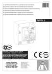
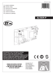
D811347 ver.03 17-07-03
I RADIOCOMANDO ROLLING-CODE PROGRAMMABILE
PROGRAMMABLE ROLLING-CODE RADIO TRANSMITTER
RADIO COMMANDE ROLLING-CODE PROGRAMMABLE
PROGRAMMIERBARE FERNSTEUERUNG MIT ROLLCODE
8 027908 196811
RADIOMANDO ROLLING-CODE PROGRAMABLE
RADIOCOMANDO ROLLING-CODE PROGRAMÁVEL
RTD
TRC 1-2-4 / MITTO 2-4 433MHz
88
88
ISTRUZIONI D'USO E DI INSTALLAZIONE
INSTALLATION AND USER'S MANUAL
INSTRUCTIONS D'UTILISATION ET D'INSTALLATION
INSTALLATIONS-UND GEBRAUCHSANLEITUNG
INSTRUCCIONES DE USO Y DE INSTALACION
INSTRUÇÕES DE USO E DE INSTALAÇÃO
Via Lago di Vico, 44
36015 Schio (VI)
Tel.naz. 0445 696511
Tel.int. +39 0445 696533
Fax 0445 696522
Internet: www.bft.it
E-mail: [email protected]
INSTALLATION MANUAL
Thank you for buying this product, our company is sure that you will be
more than satisfied with the product’s performance. The product is
supplied with a “Warnings” leaflet and an “Instruction booklet”.
These should both be read carefully as they provide important
information about safety, installation, operation and maintenance.
This product complies with the recognised technical standards and
safety regulations. We declare that this product is in conformity with
the following European Directives: 89/336/EEC and 73/23/EEC (and
subsequent amendments).
GENERAL SAFETY
WARNING! An incorrect installation or improper use of the product
can cause damage to persons, animals or things.
•
The “Warnings” leaflet and “Instruction booklet” supplied with
this product should be read carefully as they provide important
information about safety, installation, use and maintenance.
•
Scrap packing materials (plastic, cardboard, polystyrene etc)
according to the provisions set out by current standards. Keep
nylon or polystyrene bags out of children’s reach.
•
Keep the instructions together with the technical brochure for
future reference.
•
This product was exclusively designed and manufactured for the
use specified in the present documentation. Any other use not
specified in this documentation could damage the product and be
dangerous.
•
The Company declines all responsibility for any consequences
resulting from improper use of the product, or use which is
different from that expected and specified in the present
documentation.
•
Do not install the product in explosive atmosphere.
•
The construction components of this product must comply with the
following European Directives:It complies with the 89/336/EEC,
1999/5/CEE, European Directive and subsequent amendments.
As for all non-EEC countries, the above-mentioned standards as
well as the current national standards should be respected in
order to achieve a good safety level.
•
The Company declines all responsibility for any consequences
resulting from failure to observe Good Technical Practice when
constructing closing structures (door, gates etc.), as well as from
any deformation which might occur during use.
•
The installation must comply with the provisions set out by the
following European Directives:It complies with the 89/336/EEC,
1999/5/CEE, European Directive and subsequent amendments.
•
Disconnect the electrical power supply before carrying out any
work on the installation. Also disconnect any buffer batteries, if
fitted.
•
Fit an omnipolar or magnetothermal switch on the mains power
supply, having a contact opening distance equal to or greater than
3mm.
•
Check that a differential switch with a 0.03A threshold is fitted just
before the power supply mains.
•
Check that earthing is carried out correctly: connect all metal parts
for closure (doors, gates etc.) and all system components provided
with an earth terminal.
•
Fit all the safety devices (photocells, electric edges etc.) which are
needed to protect the area from any danger caused by squashing,
conveying and shearing.
•
Position at least one luminous signal indication device (blinker)
where it can be easily seen, and fix a Warning sign to the structure.
•
The Company declines all responsibility with respect to the
automation safety and correct operation when other manufacturers’
components are used.
•
Only use original parts for any maintenance or repair operation.
•
Do not modify the automation components, unless explicitly
authorised by the company.
•
Instruct the product user about the control systems provided and
the manual opening operation in case of emergency.
•
Do not allow persons or children to remain in the automation
operation area.
•
Keep radio control or other control devices out of children’s reach,
in order to avoid unintentional automation activation.
•
The user must avoid any attempt to carry out work or repair on the
automation system, and always request the assistance of qualified
12 - RTD- Ver. 03
•
personnel.
Anything which is not expressly provided for in the present
instructions, is not allowed.
1) GENERAL OUTLINE
Programmable self-learning radio receiver system, having the following
main features:
•
Receiver which can be cloned with 512 or 2048 codes
•
Up to 4 outputs (1 standard + 3 modular) with automatic recognition
of the modules entered
•
Outputs which can be configured as monostable, bistable, timed,
anti-aggression
•
Programming by means of incorporated display
•
Operation with fixed and variable codes
•
Compatible with EElink protocol for fast installation and
maintenance
•
Group function for automatic entry of groups of transmitters
•
Protection of receiver by means of password.
The RTD receiver combines the characteristics of utmost safety in
copying variable code (rolling code) coding with the convenience of
carrying out transmitter “cloning” operations thanks to an exclusive
system.
Cloning a transmitter means creating a transmitter which can be
included automatically within the list of the transmitters memorised in
the receiver, either as an addition or as a replacement of a particular
transmitter.
Therefore it will be possible to remotely program a large number of
additional transmitters, or for example, replacement transmitters for
those which have been lost, without making changes directly to the
receiver.
Replacement cloning is used to create a new transmitter which takes
the place of the one previously memorised in the receiver; in this way
the lost transmitter can be removed from the memory and no longer be
usable.
When coding safety is not a decisive factor, the RTD receiver allows
you to carry out fixed code additional cloning, which although
abandoning the variable code, provides a high number of coding
combinations, while maintaining the option of “copying” any receiver
already programmed.
Using clones when there is more than one receiver (as in the case of
communal buildings),
and especially when a distinction is to be made between clones to be
added to or replaced in individual or collective receivers, could turn out
to be rather difficult. The RTD receiver cloning system for communal
buildings makes it particularly easy to solve the problem of clone
storage for up to 250 individual receivers.
Passageway control is managed by an output with a N.O. contact;
when needed, the number of outputs can be increased by means of
appropriate MOP optional modules to obtain a maximum of 4 output
channels, which can be configured independently.
2) TECHNICAL SPECIFICATIONS
2.1) Receiver
Power supply: .................................................. 230V ±10%50Hz (*)
Frequency: ....................................................................... 433.92MHz
Working temperature: .................................................... -20 to +55°C
Coded by means of: ....................................... Rolling-code algorithm
No. combinations: ................................................................ 4 milliard
Antenna impedance: ................................................. 50 Ohm (RG58)
Dimensions: .......................................................................... see fig. 1
Relay contact: ................................................................... 0,5A, 12V=
Degree of protection: ................................................................ IP 20*
Max no. radio transmitters to be memorised:
Receiver version
No. radio transmitters
RTD 512
512
RTD 2048
2048
(*) The degree of protection of the container becomes IP55 with the
use of an accessory supplied on request. Only use fittings suitable for
the container dimensions and cable diameter.
D811347_03
ENGLISH
D811347_03
INSTALLATION MANUAL
2.2) MITTO Transmitter
Keys: .......................................................................................... yellow
Power supply: ......................... 2 3V lithium batteries (CR2016 type)
Range: ......................................................................... 50–100 metres
Transmitter versions:
MITTO2 – double-channel, MITTO4 – four-channel
2.3) TRC Transmitter
Keys: ............................................................................................... red
Power supply: ...................................................... 12V alkaline battery
Range: ......................................................................... 50–100 metres
Transmitter versions:
TRC1 – single-channel, TRC2 – double-channel, TRC4 – four-channel
Accessories (optional):
RTD-RS
Additional board for controlling the RTD receiver via modem
MOP (Fig. 2)
Plug-in module provided with an additional output with N.O. contact.
3) INSTALLATION
Having laid out the connection cable route, proceed to fixing the
support (fig. 1) after marking the two holes through the slots available
as templates on the container. Based on the material the support is
made of, directly use the screws supplied or drill the holes using a
4mm-diameter bit to insert the plugs supplied.
Fully tighten the screws, and compensate any centring errors using
the slots on the container.
4) CONNECTION DIAGRAM (Fig. 3)
Various types of installation are possible depending on the number of
outputs available.
Fig. 4 illustrates an example of an installation for an RTD receiver
provided with 4 outputs.
NOTE: For this type of installation, it is indispensable to choose the
place for the antenna with great care.
RTD
JP4
1-2
JP3
3
4
Power supply input 230 V
±10% 50/60Hz(1L-2N)
Output for COM common contact
Output for NO normally open contact. Contact for door opening
control
JP2
5-6
Input for antenna (5 signal – 6 braid)
JP7-JP8-JP9
Plug-in inputs for MOP optional modules
MOP (optional)
JP1
1-2
Output for NO normally open contact. Contact for door opening
control.
ANTENNA INSTALLATION
Use an antenna tuned to 433MHz.
For antenna to receiver connection, use RG8 coaxial cable.
The presence of metallic masses next to the antenna can interfere
with radio reception. In the case of insufficient transmitter range,
move the antenna to a more suitable position.
5) PROGRAMMING
Transmitters can be memorised by means of the incorporated display
programmer or the UNIRADIO programmer, which makes it possible
to create installations in the “collective receivers” mode, as well as
manage the complete installation database through the EEdbase
software.
In the case of standard installations where no advanced functions are
required, it is possible to proceed to manual transmitter storage,
making reference to programming tables A and B.
ENGLISH
Programming menu description
Add:
Allows you to add a transmitter to a receiver memory.
Three modes can be used:
Auto: the transmitter is entered in the first memory location
available.
Manual: the number of the memory location where to enter
the transmitter is requested. This mode turns out to be useful
in the case where you wish to assign progressive numbers to
the various transmitters, in order to simplify any subsequent
elimination from the receiver memory.
Group: menu for automatic entry of groups of transmitters.
See paragraph 5.1 “Transmitter groups”.
After selecting the automatic mode, proceed as follows:
1) Use the + and – buttons to select the output you wish to activate.
If the “all outputs” option is selected, each transmitter key is
automatically associated with its corresponding output (T1– Output
1, T2 – Output 2 etc.).
2) Press hidden key P1 on the transmitter.
3) Press the required transmitter key (T1, T2, T3 or T4) you wish to
associate with the previously selected output.
Note: Hidden key P1 has a different function depending on the
transmitter model.
For TRC 1-2 / MITTO 2-4, press hidden key P1 (fig. B1A).
For TRC 4, the key P1 function corresponds to simultaneously pressing
the 4 transmitter keys or, after opening the battery compartment,
bridging the two P1 points by means of a screwdriver (fig. B1A).
The cloned transmitters are automatically entered in the first memory
location available.
IMPORTANT NOTE: STICK THE KEY LABEL (MASTER) ON THE
FIRST MEMORISED TRANSMITTER.
In the case of manual programming, the first transmitter assigns the
key code to the receiver; this code is necessary in order to carry out
subsequent cloning of the radio transmitters.
Delete:
Allows you to delete one or all the entered transmitters from the
receiver memory.
Code: allows you to eliminate a transmitter from the receiver
memory by entering the memory position number (see Addmanual menu).
List: allows you to eliminate ALL the transmitters from the
receiver memory. You will be requested to confirm this
operation in order to avoid unwanted deletions.
Verify:
Allows you to check the presence of a transmitter in the memory, or
to display the list of all the transmitters entered.
Read code: requires you to press a key on the transmitter
and, if memorised, it displays the memory location number
and the key number.
Scroll list: press the + and - buttons to scroll the list of all the
radio transmitters memorised; keep the button pressed to
speed up list scrolling.
Output:
Allows you to configure the functions of the outputs available in the
receiver.
Configure outputs 1, 2, 3 and 4: select the output you wish
to configure using the + and – buttons.
Each output can be configured according to the following
modes:
1)
impulse (monostable). The relay of the associated output
remains picked up as long as the respective transmitter key
remains pressed.
2)
step by step (bistable). The relay of the associated output
changes status each time the transmitter key is pressed.
3)
timed. Each time the transmitter key is pressed, the output
relay stays picked up for 90 seconds. If the key is pressed
during the count cycle, the count is reset).
RTD- Ver. 03 - 13
INSTALLATION MANUAL
4)
anti-panic. The relay of the associated output changes status
if the key is kept pressed for more than 5 seconds. All the keys
of all the transmitters entered in the receiver are automatically
provided with the anti-aggression function, regardless of their
configuration, therefore no key (T1, T2, T3 or T4) needs to be
assigned to the output. Relay commutation lasts 10 sec.
Notes: The default outputs are configured as monostable.
Only one output can be configured with anti-aggression mode.
In the case where it is necessary to check the mode of an output
configuration, select the output and press the OK key. The receiver
displays the previously set function mode as the first option.
If you try to configure an output which is not provided with a MOP
option module, the “module not present” error message will be
displayed.
Configure RTD:
Allows you to set the general system functions.
Language: select one of the languages available (Italian,
French, German, English, Spanish).
Password: use the + and - buttons to enter a password
consisting of 4 digits (from 0 to 9). If a value other than the
default value (0000) is entered, the access password will be
requested for the subsequent configuration attempt. If you do
not wish to protect receiver programming by means of a
password, re-enter default value 0000.
Type of receiver: select the receiver function mode between
fixed code and variable code (rolling-code); the receiver
default configuration is set to rolling-code mode.
5.1) Transmitter groups
Use menu Add --> Group to enter a large number of transmitters
automatically (the maximum limit being the receiver memory capacity).
The company markets packs containing 100 transmitters, appropriately
programmed and numbered from 01 to 100 (transmitter 100 is identified
by figure 00), which can be entered as groups.
Entering a group simply requires the storage of the first and last
transmitters, all the group transmitters included between these will
automatically be stored in the memory.
RTD receiver memory locations
In order to maintain some kind of uniformity with the transmitter
numbering, the receiver memory locations are assigned as follows:
1) If the memory is empty, the first transmitter (ex. 01) is entered in
location 01 and the others follow, as indicated:
RTD
01 02 03 04 05 06
--
--
--
--
--
-- 100
01 02 03 04 05 06
--
--
--
--
--
--
00
2) If some of the locations are taken up by other transmitters, the first
transmitter (ex. 01) is entered in the first “N01” (101-201-301, etc.)
location available, which is followed by a sufficient number of free
entry locations:
RTD
01 02 03 04 05 --
-- 101 102 103 --
01 02 03
--
-- 200
--
00
3) If the receiver is empty and the first transmitter has a number other
than 01 (ex. 35), the first transmitter is entered in location 35, and
the others follow:
RTD
Standard transmitters cannot be entered in the group menu.
To enter transmitter groups, proceed as follows:
1) Move to menu Add --> Group and select the output to be activated.
Select option “all outputs” to have each transmitter key automatically
associated with the corresponding output (T1- Output1, T2 Output2 etc.).
2) The display shows the message “First transmitter” and then
“hidden key”, press the hidden key (P1 - Fig.5) of the first
transmitter (lowest number) you wish to enter.
3) The display shows the message “key required”: press the Tx key
you wish to associate with the output selected previously.
4) The display shows the message “Last transmitter” and then
“hidden key”, press the hidden key (P1) of the last transmitter
(highest number) you wish to enter.
5) The display shows the message “key required”, press the Tx key
of the last transmitter.
Note: the Tx key selected during this phase must be the same as
that selected in point 3.
6) The display shows the first memory location taken up, confirm by
pressing the “OK” key and the display will show the last memory
location taken up, then press the “OK” key again. In the case
where you wish to cancel a group entered, press the + and – keys
at the same time.
14 - RTD- Ver. 03
01 02 03
--
--
--
35 36 37 38 --
-- 100
35 36 37 38 --
--
00
4) If some of the locations are taken up and the first transmitter has
a number other than 01 (ex. 35), it is entered in the first “N35” (135235-335 etc.) location available, which is followed by a sufficient
number of free entry locations:
RTD
--
35 36 37 38 39
-- 135 136 137 --
-- 200
35 36 37
-- 00
--
D811347_03
ENGLISH
D811347_03
INSTALLATION MANUAL
5)
In the case where more than 100 transmitters need to be stored
in the memory, each individual sales pack has to be entered by
means of the group menu. Each pack is identified by a specific
serial number (S/N):
RTD
01 --
01 --
-- 100 101 --
--
S/N 123.4
00 01
--
-- 200 201 --
--
S/N 123.4
00 01
--
-- 300 --
--
00 --
ENGLISH
9) DISPOSAL
ATTENTION: disposal should only be carried out by qualified
personnel.
Materials must be disposed of in conformity with the current regulations.
In case of disposal, the system components do not entail any particular
risks or danger. In case of recovered materials, these should be sorted
out by type (electrical components, copper, aluminium, plastic etc.).
For battery disposal, refer to the current regulations.
The descriptions and illustrations contained in the present manual
are not binding. The Company reserves the right to make any
alterations deemed appropriate for the technical, manufacturing
and commercial improvement of the product, while leaving its
essential features unchanged, at any time and without undertaking
to update the present publication.
S/N 123.4
IMPORTANT NOTES:
•
The sales pack can be divided into several groups (for ex.
transmitters from 01 to 50 in one system, from 51 to 65 in another,
etc.) In any case, any of the remaining transmitters can be used:
- on the same RTD receiver at a later time, in other groups or with
manual/automatic mode,
- in other RTD systems, other groups or with manual/automatic
mode,
- in other transmitters with standard mode.
•
Each transmitter contained in the pack is individually labelled
according to the following sequence: 123.4.01.
The first four figures (123.4) identify the pack serial number which
is identical for all the transmitters belonging to the same pack.
The last two figures (01 - 02 --> 00) are used to number the
transmitters in the pack in progressive order.
Each pack includes a printed form where to record the destination
of each transmitter, you are recommended to fill it in to facilitate
future maintenance, updating, replacement etc.
•
In the case where no transmitters have been previously entered
in the RTD receiver, the first transmitter in the first group stored
takes on the master transmitter function. Mark it with the appropriate
adhesive “key” label.
Error messages
If any errors occur when entering groups, check that:
the transmitters belong to one group pack (ERR1);
the entry order is not reversed, the first transmitter must have an
identification number lower than that of the last one. Also check
that the first and last transmitters belong to the same group
(ERR2);
the receiver has a sufficient number of consecutive free locations
for entering the transmitter group (ERR3);
the key assigned to the channel (T1, T2, T3 or T4) is the same for
the first and the last transmitter entered.
6) RADIO-TRANSMITTER CLONING
Rolling-code cloning / Fixed-code cloning
Make reference to the UNIRADIO Instructions and the CLONIX
Programming Guide.
7) ADVANCED PROGRAMMING: COLLECTIVE RECEIVERS
Make reference to the UNIRADIO Instructions and the CLONIX
Programming Guide.
8) MAINTENANCE
The maintenance of the system should only be carried out by
qualified personnel regularly. The MITTO transmitters are supplied
by two 3V lithium battiers (type CR2016).The TRC transmitters are
powered by a 12V alkaline battery.When replacing the batteries type
CR2016 do not touch the poles with thehands.
Any reduction in the transmitter capacity may be due to the batteries
getting flat. When the led of the transmitter flashes, it means that the
batteries are
flat and must be replaced.
RTD- Ver. 03 - 15
LEGENDA
ACCESS TO MENUS
+/-
8888
Press the OK key
OK
+
OK
BFT
RTD1.0
00
[ 00 ]
Software version
- +
PRG
Preset value
Message: Programming in progress
Parameter increment/reduction
or ON/OFF commutation
Message: KO! (value or function error)
Menu scrolling
(+ = preceding - = following)
Message: “Wait” (enter value or function)
/ON
/OFF
No. radio control devices
memorised
OK
Simultaneously press the + and - keys.
Simultaneous pressure of the + and – keys
allows you to exit the active menu and return
to the preceding menu; if this takes place at
the main menu level, programming is exited
and the display switched off.
The modifications made are only confirmed if
the OK key is subsequently pressed.
+/ADD
OK
aut.
out1 . .4
- +
+/-
- +
man.
END
ALL
out1 . .4
pos.
OK
hidden button
P1
desired button
Tx
desired button
Tx
- +
ALL
Group
out1 . .4
OK
First tras.
hidden button
P1
- +
- +
ALL
0100
OK
OK
0001
Tx
desired button
+/delete
OK
code
+/-
database
End
pos.
t0001 . . .
- +
confirm
OK
- +
+/verify
OK
read code
01 t1 . . . 2048 t4
- +
+/-
scroll archive
End
- +
FOLLOWING
MENUS FIG. B
16 - RTD- Ver. 03
01 t1 . . . 2048 t4
OK
P1
hidden button Last tras.
D811347_03
Fig. A
D811347_03
Fig. B
FIG. B2A
FIG. B1A
P1
PRECEDING
MENUS FIG. A
T1
T2 T1
T2
P1
T1
TRC 1-2
T3
T4
MITTO 2-4
TRC 4
T1
T2
T3
T4
T2
TRC 1-2
TRC 4
+/output
OK
+/END
- +
out1
monos
OK
- +
- +
out 2
bist
- +
- +
out 3
timed
- +
- +
out 4
OK
antipanic
+/configure RTD
language
ita
OK
- +
+/-
fra
- +
END
deu
- +
- +
ENG
- +
ESP
password
0---
-0--
--0-
---0
OK
- +
rec. type
codice fisso
OK
- +
rolling code
RTD- Ver. 03 - 17
44
35
T2
T1
75
75
T1
12.5
T1
T2
T1
T4
T2
T2
82
65
T3
T3
16
16
T4
45
16
45
MITTO 2
TRC 1-2
MITTO 4
34
0
11
7
14
42 - RTD- Ver. 03
TRC4
18.5
D811347_03
Fig. 1
D811347_03
Fig. 2
8
88
8
RTD- Ver. 03 - 43
D811347_03
Fig. 3
100 mA T
1 2
JP5
RTD
+
OK
5 6
3 4
RTD
44 - RTD- Ver. 03
4
DOOR
JP2 5
6
ANT.
JP1
MOP
1
2
NO
N
3
SHIELD
L
JP3
ANT
2
NO
1
COM
JP4
NO
COM
NO
DOOR
D811347_03
Fig. 4
m
2x1,5m
RG58
T1- OUT1
2x1mm
2
RTD
2x1m
m2
T3
A
2
OU
OU
T1
T2- OUT2
2x
1m
m2
2x
1m
m2
T3- OUT3
T4
OUT2
OU
T4- OUT4
RTD- Ver. 03 - 45
D811347_03
Fig. 5
C4
TR
P1
T1
T1 2
T 3
T 4
T
TRC 1-2
T2
Led
MITTO 2-4
P1
P1
P1
Fig. 6
RTD
UNIRADIO
UNIFLAT
88
88
Contatti
Contacts
Contacts
Kontakte
Contactos
Contatos
UNIFLAT
UNIFLAT
Contatti
Contacts
Contacts
Kontakte
Contactos
Contatos
UNITRC
UNIFLAT
TRC4
UNITRC
UNIMITTO
TRC1-2
Contatti
Contacts
Contacts
Kontakte
Contactos
Contatos
UNITRC
MITTO 2-4
TRC1-2
TRC4
2
UNIMITTO
1
3
46 - RTD- Ver. 03
1
4
2
3
4