1
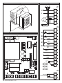
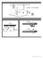
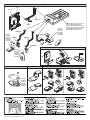
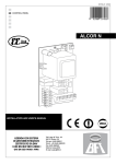
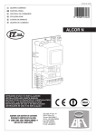
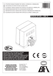
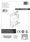
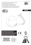
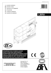
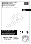
D811430 ver. 06 11/04/07
GB CONTROL PANEL
8
027908
240637
ALPHA - ALPHA BOM
INSTALLATION AND USER'S MANUAL
Via Lago di Vico, 44
36015 Schio (VI)
Tel.naz. 0445 696511
Tel.int. +39 0445 696533
Fax 0445 696522
Internet: www.bft.it
E-mail: [email protected]
D811430_06
- ALPHA-ALPHA BOM - Ver. 06
D811430_06
ENGLISH
USER’S MANUAL
Thank you for buying this product, our company is sure that you will
be more than satisfied with the product’s performance. The product
is supplied with a “ Warnings ” leaflet and an “ Instruction booklet ”.
These should both be read carefully as they provide important
information about safety, installation, operation and maintenance.
This product complies with the recognised technical standards and
safety regulations. We declare that it is in conformity with the follow ing European Directives: 89/336/EEC, 73/23/EEC and subsequent
amendments.
1) GENERAL OUTLINE
The ALPHA-ALPHA BOM mod. control units have been designed
to control one single operator.
2) SCRAPPING
Warning: This operation should only be carried out by quali
fied personnel. Materials must be disposed of in conformity with
the current regulations. In case of scrapping, the automation devices
do not entail any particular risks or danger. In case of materials to be
recycled, these should be sorted out by type (electrical components,
copper, aluminium, plastic etc.).
3) DISMANTLING
Warning:This operation should only be carried out by qualified
personnel. When the control unit is disassembled to be reassembled
on another site , proceed as follows:
• Disconnect the power supply and the entire electrical installa
tion.
• In the case where some of the components cannot be removed
or are damaged, they must be replaced.
-
4) WARNING
• Make sure that an omnipolar or magnetothermal switch, having
a contact opening distance equal to or greater than 3,5 mm, is
fitted to the automation power supply mains.
• Make sure that a differential switch with a 0.03A threshold is fitted
before the power supply mains.
• Make sure that all safety devices installed on the gate are always
in working order; otherwise, disconnect the power supply, release
the motors and immediately request assistance from qualified
personnel.
• Do not allow persons or children to remain within the automation
operation area.
• Keep radio control or other control devices out of children’s reach,
in order to avoid unintentional automation activation.
• The user must avoid any attempt to carry out work or repair on
the automation system, and always request the assistance of
qualified personnel.
Correct controller operation is only ensured when the data
contained in the present manual are observed. The company
is not to be held responsible for any damage resulting
from failure to observe the installation standards
and the
instructions contained in the present manual.
The descriptions and illustrations contained in the present
manual are not binding.The Company reserves the right to make
any alterations deemed appropriate for the technical, manu
facturing and commercial improvement of the product, while
leaving the essential product features unchanged, at any time
and without undertaking to update the present publication.
-
ALPHA-ALPHA BOM - Ver. 06 - 3
D811430_06
ENGLISH
INSTALLATION MANUAL
Thank you for buying this product, our company is sure that you will
be more than satisfied with its performance.
This product is supplied with an “Instruction Manual” which should
be read carefully as it provides important information about safety,
installation, operation and maintenance.
This product complies with recognised technical standards and safety
regulations. We declare that it is in conformity with the following European
Directives: 89/336/EEC, 73/23/EEC and subsequent amendments.
1) GENERAL SAFETY
WARNING! An incorrect installation or improper use of the
product can cause damage to persons, animals or things.
• The “Warnings” leaflet and “Instruction booklet” supplied with
this product should be read carefully as they provide important
information about safety, installation, use and maintenance.
• Scrap packing materials (plastic, cardboard, polystyrene etc)
according to the provisions set out by current standards. Keep
nylon or polystyrene bags out of children’s reach.
• Keep the instructions together with the technical brochure for
future reference.
• This product was exclusively designed and manufactured for the
use specified in the present documentation. Any other use not
specified in this documentation could damage the product and
be dangerous.
• The Company declines all responsibility for any consequences
resulting from improper use of the product, or use which is different
from that expected and specified in the present documentation.
• Do not install the product in explosive atmosphere.
• The construction components of this product must comply with
the following European Directives: 89/336/CEE, 73/23/EEC,
98/37/EEC and subsequent amendments. As for all non-EEC
countries, the above-mentioned standards as well as the current
national standards should be respected in order to achieve a good
safety level.
• The Company declines all responsibility for any consequences
resulting from failure to observe Good Technical Practice when
constructing closing structures (door, gates etc.), as well as from
any deformation which might occur during use.
• The installation must comply with the provisions set out by the
following European Directives: 89/336/CEE, 73/23/EEC, 98/37/
EEC and subsequent amendments.
• Disconnect the electrical power supply before carrying out any
work on the installation. Also disconnect any buffer batteries, if
fitted.
• Fit an omnipolar or magnetothermal switch on the mains power
supply, having a contact opening distance equal to or greater
than 3,5 mm.
• Check that a differential switch with a 0.03A threshold is fitted
just before the power supply mains.
• Check that earthing is carried out correctly: connect all metal
parts for closure (doors, gates etc.) and all system components
provided with an earth terminal.
• Fit all the safety devices (photocells, electric edges etc.) which are
needed to protect the area from any danger caused by squashing,
conveying and shearing.
• Position at least one luminous signal indication device (blinker) where
it can be easily seen, and fix a Warning sign to the structure.
• The Company declines all responsibility with respect to the automation
safety and correct operation when other manufacturers’ components
are used.
• Only use original parts for any maintenance or repair operation.
• Do not modify the automation components, unless explicitly
authorised by the company.
• Instruct the product user about the control systems provided and
the manual opening operation in case of emergency.
• Do not allow persons or children to remain in the automation operation
area.
• Keep radio control or other control devices out of children’s reach,
in order to avoid unintentional automation activation.
• The user must avoid any attempt to carry out work or repair on
the automation system, and always request the assistance of
qualified personnel.
• Anything which is not expressly provided for in the present instructions, is not allowed.
• Installation must be carried out using the safety devices and
controls prescribed by the EN 12978 Standard.
2) GENERAL OUTLINE
The ALPHA-ALPHA BOM mod. control units have been designed
to control one single operator.
3) TECHNICAL DATA
Power supply: ................................................. 230V±10%, 50Hz(*)
Mains insulation/very low voltage: ........................> 4MΩ, 500V
Working temperature:................................................... -10 / +55°C
Max. motor power absorbed: ................................................. 500W
Dielectric strength:…. .........mains/low voltage 3750V~for 1 minute
Gate-open warning light:..........................................24V~, 3W max
Supply to accessories:....................... 24V~, (0.2A max absorption)
Incorporated Rolling-Code radio receiver:... Frequency 433.92MHz
Coding:...................................Rolling-Code Algorithm to be cloned
No. combinations:............................................................ 4 milliard
Antenna impedance:............................................... 50Ohm (RG58)
Max no. radio transmitters to be memorised:.............................. 63
Dimensions:...................................................................see figure 1
(* other voltages available on request)
4) TERMINAL BOARD CONNECTIONS (Fig.2)
For the electric diagram and the cross section of the cables refer to
the manual of the actuator.
WARNING – During the wiring and installation operations, refer to the
current standards as well as principles of good technical practice.
Wires powered at different voltages must be physically separated,
or suitably insulated with at least 1 mm extra insulation. The wires
must be clamped by an extra fastener near the terminals, for example by bands.
All the connection cables must be kept at an adequate distance
from the dissipator.
Connect the yellow/green conductor of the power supply cable to
the earth terminal.
230V cables must be physically separate from the safety very low
voltage circuits.
Keep the mains voltage connections definitely separate from the
(24V) very low voltage connections.
The capacitors inside the control unit must be positioned in such a
way as not to decrease the surface and air distances with respect
to the safety very low voltage.
WARNING! For connection to the mains, use a multipolar cable
with a minimum of 3x1.5mm2 cross section and complying with
the previously mentioned regulations. For example, if the cable is
out side (in the open), it has to be at least equal to H07RN-F, but if
it is on the inside (or outside but placed in a plastic cable cannel)
it has to be or at least egual to H05VV-F with section 3x1.5mm2.
JP1
1-2 Power supply 230V +/- 10% 50/60 Hz (Neutral to terminal 1).
3-4-5 Connection to motor M (terminal 4 common, terminals 3-5
motor and capacitor drive).
1-4 Connection to blinker and electric lock 230V mod. EBP.
JP2
7-8 Alpha: START or key selector input (N.O.)
Alpha BOM:
START or key selector input (N.O.) with trimmer TW=max.
OPEN input (N.O.) with trimmer TW=min.
7-9 STOP pushbutton (N.C.). If not used, leave the bridge connected.
7-10 Photocell input or pneumatic edge (N.C.). If not used, leave
the bridge connected.
7-11 Opening limit switch (N.C.). If not used, leave the bridge connected.
ALPHA-ALPHA BOM - Ver. 06 - INSTALLATION MANUAL
7-12 Closing limit switch (N.C.). If not used, leave the bridge connected.
13-14Output 24V~supply to photocells or other devices.
15-16Output for gate-open warning light outputor alternatively 2nd
radio channel.
17-18Antenna input for radio-receiver plug-in board (17 signal-18
braid).
JP3
19-20Alpha: PEDESTRIAN input (N.O.)
Alpha BOM: PEDESTRIAN input (N.O.) with trimmer
TW=max.
CLOSE input (N.O.) with trimmer TW=min.
WARNING: the pedestrian function can be used provided that
limit switches are fitted.
JP4 Radio-receiver board connector, 1-2 channels.
Fig.7 shows a general wiring diagram.
5) LED (Fig.3)
The ALPHA-ALPHA BOM control units are provided with a series
of self-diagnosis LEDs which control all the functions.
DL1:Incorporated radio receiver LED
DL2:Alpha: comes on with the START command
Alpha BOM:
START (trimmer TW=max)-comes on with the START command
OPEN (trimmer TW=min)-comes on with the OPEN command
DL3:STOP - goes off when a STOP command is given.
DL4:PHOT - Photocell - goes off when the photocells are not aligned
or in the presence of obstacles.
DL5:SWO - Goes off when the opening limit switch is operated.
DL6:SWC - Goes off when the closing limit switch is operated.
6) DIP-SWITCH SELECTION (Fig.3)
DIP1)
TCA [ON] - Automatic closing time TCA.
ON: Activates automatic closing
OFF:Excludes automatic closing
DIP2)
FCH [ON] - Photocells.
ON: Photocells are only active in the closing phase.
OFF:Photocells are active both in the closing and opening phase.
DIP3)
BLI - Blocks impulses.
ON: START commands are not accepted during the opening phase.
OFF:START commands are accepted during the opening phase.
DIP4)
3P/4P - 3 Steps/4 Steps
ON: Enables 3-step logic.
OFF:Enables 4-step logic.
DIP5)
CODE FIX – Fixed code.
ON: Activates incorporated receiver in fixed code mode.
OFF:Activates incorporated receiver in rolling-code mode.
DIP6)
RADIO LEARN - Radio transmitter programming
ON: This enables transmitter storage via radio:
1 – First press the hidden key (P1) and then the normal key (T1,
T2, T3 or T4) of a transmitter already memorised in standard
mode by means of the radio menu.
2 – Within 10s press the hidden key (P1) and the normal key
(T1, T2, T3 or T4) of a transmitter to be memorised.
The receiver exits the programming mode after 10s, other new
transmitters can be entered before the end of this time.
This mode does not require access to the control panel.
OFF:This disables transmitter storage via radio. The transmitters
are only memorised by means of manual programming.
DIP7)
SCA – Gate-open warning light or 2nd radio channel.
OFF:Activates relay output in Gate-open warning light mode.
ON: Activates relay output as 2nd radio channel.
DIP8)
10 - ALPHA-ALPHA BOM - Ver. 06
FAST CLOSE
ON: Closes the gate after photocell disengagement, before waiting
for the end of the TCA set.
OFF:Command not entered.
7) TRIMMER ADJUSTMENT (Fig.3)
TCA (Dip1 ON).
It is used to set the automatic closing time, after which the gate
closes automatically (adjustable from 0 to 90 s.).
TW
Alpha: Sets the motor working time (from 0 to 90s), after
which the motors stop.
In the case where electrical limit switches are used,
add a few extra seconds after the gate leaf stopping
time.
Alpha BOM: Working time is fixed to 10s.
trimmer TW = min: inputs 7-8 and 19-20 are considered as OPEN and
CLOSE inputs respectively.
trimmer TW = max: inputs 7-8 and 19-20 are considered as START
and PEDESTRIAN inputs respectively.
8) INTEGRATED RECEIVER TECHNICAL SPECIFICATION
Receiver output channels:
-output channel 1, if activated, controls a START command
-output channel 2, if activated, controls the excitation of the 2nd
radio channel relay for 1s.
Transmitter versions which can be used:
all Rolling Code transmitters compatible with
.
ANTENNA INSTALLATION
Use an antenna tuned to 433MHz.
For Antenna-Receiver connection, use RG8 coaxial cable.
The presence of metallic masses next to the antenna can interfere
with radio reception. In case of insufficient transmitter range, move
the antenna to a more suitable position.
9) PROGRAMMING
Transmitter storage can be carried out in manual mode, or by means
of the Universal palmtop programmer which allows you to create
installations in the “collective receivers” mode, as well as manage
the complete installation database using the EEdbase software.
10) MANUAL PROGRAMMING
In the case of standard installations where no advanced functions
are required, it is possible to proceed to manual storage of the
transmitters
1)If you wish the transmitter T key to be memorised as Start, press
thSW1 button on the control unit, otherwise if you wish the transmitter
key to be memorise as second radio channel, press the SW2 button
on the control unit.
2)When the DL1 LED blinks, press the transmitter P1 hidden key,
and the DL1 LED will stay on permanently.
3)Press the key to be memorised on the transmitter, LED DL1 will
start blinking again.
4)To memorise another transmitter, repeat steps 2) and 3).
5)To exit the storage mode, wait until the LED is switched off completely.
IMPORTANT NOTE: ATTACH THE ADHESIVE KEY LABEL TO
THE FIRST MEMORISED TRANSMITTER (MASTER).
In the case of manual programming, the first transmitter assigns the
key code to the receiver; this code is necessary in order to carry out
subsequent cloning of the radio transmitters.
10.1) CONTROL UNIT MEMORY CANCELLATION
In order to cancel the control unit memory completely, simultaneously
press for 10 seconds the SW1 and SW2 buttons on the control unit
(DL1 LED blinking). Correct memory cancellation will be indicated
by the DL1 LED staying on permanently. To exit the storage mode,
wait until the LED is switched off completely.
D811430_06
ENGLISH
D811430_06
INSTALLATION MANUAL
ENGLISH
11) RECEIVER CONFIGURATION
The on-board receiver combines characteristics of utmost safety in
copying variable code (rolling code) coding with the convenience of
carrying out transmitter “cloning” operations thanks to an exclusive
system.
Cloning a transmitter means creating a transmitter which can be
automatically included within the list of the transmitters memorised
in the receiver, either as an addition or as a replacement of a particular transmitter.
Cloning by replacement is used to create a new transmitter which
takes the place of the one previously memorised in the receiver; in
this way a specific transmitter can be removed from the memory and
will no longer be usable.
Therefore it will be possible to remotely program a large number
of additional transmitters or, for example, replacement transmitters
for those which have been lost, without making changes directly to
the receiver.
When coding safety is not a decisive factor, the on-board receiver
allows you to carry out fixed-code additional cloning which, although
abandoning the variable code, provides a high number of coding
combinations, therefore keeping it possible to “copy” any transmitter
which has already been programmed .
12) RADIO-TRANSMITTER CLONING (Fig.7)
Rolling-code cloning / Fixed-code cloning
Make reference to the universal palmtop programmer instructions
and the CLONIX Programming Guide.
12.1) ADVANCED PROGRAMMING: COLLECTIVE RECEIVERS
Make reference to the universal palmtop programmer Instructions
and the CLONIX Programming Guide.
13) ACCESSORIES
SPL (fig.4).
Pre-heating optional board. Recommended for temperatures below
-10°C. (In the case of hydraulic motors).
ME (fig.5).
Optional board used to connect a 12V~ electric lock.
Note: the ME optional board is not operated by the START control
of the integrated radio board. For the correct functioning of the ME
optional board use one of the following configurations:
1.use the second radio channel as START control and perform the
necessary connections to the terminal board.
2.use the plug-in radio receiver.
EBP (fig.2).
The EBP electric lock with continuous service can be connected
directly to terminals 1 and 4.
14) SCRAPPING
Warning: This operation should only be carried out by qualified
personnel. Materials must be disposed of in conformity with the
current regulations. In case of scrapping, the automation devices do
not entail any particular risks or danger. In case of materials to be
recycled, these should be sorted out by type (electrical components,
copper, aluminium, plastic etc.).
15) DISMANTLING
Warning: This operation should only be carried out by qualified
personnel. When the control unit is disassembled to be reassembled
on another site, proceed as follows:
• Disconnect the power supply and the entire electrical installation.
• In the case where some of the components cannot be removed
or are damaged, they must be replaced.
The descriptions and illustrations contained in the present
manual are not binding.The Company reserves the right to make
any alterations deemed appropriate for the technical, manufacturing and commercial improvement of the product, while
leaving the essential product features unchanged, at any time
and without undertaking to update the present publication.
ALPHA-ALPHA BOM - Ver. 06 - 11
Fig. 2
D811430_06
Fig. 1
JP1
120
N
1
L
2
207
3
M
4
5
236
EBP
100
JP2
194
7
Fig. 3
NA
START (ALPHA)
START/OPEN (ALPHA BOM)
8
NC
STOP
9
NC
PHOT
10
NC
SW.O
11
NC
SW.C
12
0V
24V~
2CH
SCA
13
14
15
16
17
ANTENNA
ANTENNE
ANTENNA
ANTENA
ANTENNE
ANTENNE
PED(ALPHA)
PED/CLOSE(ALPHA BOM)
24 - ALPHA-ALPHA BOM - Ver. 06
18
JP3
19
20
2
3
4
5
7
8
9
10 11 12 13 14 15 16 17 18
M1
1
24V ~
D811430_06
Fig. 4
ALPHA - ALPHA BOM
1 2 3 4 5 6
SPL
-8
+8
0
Fig. 5
Fig. 6
ALPHA
ALPHA BOM
ALPHA
ALPHA BOM
2
3
4
5
7
8
9
230V
ME
8
9
10 11 12 13 14 15 16 17 18
10 11 12 13
1 2 3 4
1
7
SCA
ALPHA
ALPHA BOM
12V
7
8
9
10 11 12 13 14 15 16 17 18
ALPHA-ALPHA BOM - Ver. 06 - 25
D811430_06
Fig. 7
4
JP6
ALPHA
UNIFLAT
Programmatore palmare universale
Universal palmtop programmer
Programmateur de poche universel
Universellen Palmtop-Programmierer
Programador de bolsillo universal
Programador palmar universal
UNIDA
Contatti
Contacts
Contacts
Kontakte
Contactos
Contatos
UNIFLAT
Contatti
Contacts
Contacts UNITRC
Kontakte
Contactos
Contatos
UNIFLAT
UNIFLAT
UNITRC
UNIMITTO
P1
Contatti
Contacts
Contacts
Kontakte
Contactos
Contatos
T1
T1 2
T 3
T 4
T
T2
Led
P1
P1
P1
P1
UNIMITTO
P1
UNITRC
1
Contatti
Contacts
Contacts
Kontakte
Contactos
Contatos
3
26 - ALPHA-ALPHA BOM - Ver. 06
2
1
4
3
2
4