1
Introduction
This manual is referred to when using the C70.
This manual explains how to operate the screens of the C70. Read this manual thoroughly before using the CNC unit. To
safely use this CNC unit, thoroughly study the "Precautions for Safety" on the next page before use.
Details described in this manual
CAUTION
For items described in "Restrictions" or "Usable State", the instruction manual issued by the machine
manufacturer takes precedence over this manual.
An effort has been made to note as many special handling methods in this user's manual. Items not
described in this manual must be interpreted as "Not Possible".
This manual has been written on the assumption that all option functions are added.
Refer to the specifications issued by the machine manufacturer before starting use.
Refer to the manuals issued by the machine manufacturer for each machine tool explanation.
Some screens and functions may differ or may not be usable depending on the NC version.
[Important Usage Notes]
In this NC unit, the machining programs, parameters and tool compensation data are saved in the memory
(memory elements). This NC unit's memory is backed up by lithium batteries, and under normal conditions will last
6 years from the date of manufacture. However, data contents could be lost under the conditions described below.
To prevent data loss, output important programs, parameters, etc., to the external memory devices and save them.
Data in the memory can be lost under these kinds of conditions.
(1)
Incorrect operation
Data can be lost if the operator inadvertently changes data while editing a program or setting parameters.
(This is not really a data loss, but it is a loss from the standpoint that the original data is gone.)
Data can be lost if the operator inadvertently deletes data or initializes NC unit.
(2) Battery life expires
When the battery life expires and there is not enough voltage to store the data in the memory, data can be lost
by turning the power OFF.
(3) Faults
Data can be lost when faults occur and the control unit must be replaced.
Precautions for Safety
Always read the specifications issued by the machine manufacturer, this manual, related manuals and attached
documents before installation, operation, programming, maintenance or inspection to ensure correct use.
Understand this numerical controller, safety items and cautions before using the unit.
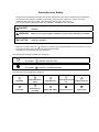
This manual ranks the safety precautions into "DANGER", "WARNING" and "CAUTION".
DANGER
WARNING
CAUTION
When the user may be subject to imminent fatalities or major injuries if handling is
mistaken.
When the user may be subject to fatalities or major injuries if handling is mistaken.
When the user may be subject to injuries or when physical damage may occur if
handling is mistaken.
Note that even items ranked as "
CAUTION", may lead to major results depending on the situation. In any case,
important information that must always be observed is described.
The meanings of the pictorial signs are given below.
The following signs indicate prohibition and compulsory.
This sign indicates prohibited behavior (must not do).
For example,
indicates "Keep fire away".
This sign indicated a thing that is pompously (must do).
For example,
indicates "it must be grounded".
The meaning of each pictorial sign is as follows.
CAUTION
CAUTION rotated
object
CAUTION HOT
Danger Electric shock
risk
Danger explosive
Prohibited
Disassembly is
prohibited
KEEP FIRE AWAY
General instruction
Earth ground
For Safe Use
Mitsubishi CNC is designed and manufactured solely for applications to machine tools to be used for industrial
purposes.
Do not use this product in any applications other than those specified above, especially those which are
substantially influential on the public interest or which are expected to have significant influence on human lives or
properties.
DANGER
1. Items related to maintenance
Do not touch the terminals while power is on. Doing so could cause electric shock.
Correctly connect the battery. Also, do not charge, disassemble, heat, place in fire, short circuit, or solder
the battery.
Mishandling of a battery may cause overheating, cracks or ignition which could result in injury and fire.
Switch off all phases of the externally supplied power used in the system when cleaning the module or
retightening the terminal or module mounting screws.
Not doing so could result in electric shock. Loose tightening of terminal screws can cause a short circuit or
malfunction. Over tightening of screws can cause damages to the screws and/or the module, resulting in
fallout, short circuits, or malfunction.
The capacitor is mounted to the modules. Do not incinerate the modules so that the incineration of
capacitor may cause burst. For disposal of the modules, request for specialized industrial waste disposal
services who has incineration facility.
2.Items related to inspection
Never open the front case or terminal covers while the power is ON or the unit is running, as this may lead
to electric shocks.
Never run the unit with the front case or terminal cover removed. The high voltage terminal and charged
sections will be exposed and may lead to electric shocks.
Never remove the front case or terminal cover at times other than wiring work or periodic inspections even
if the power is OFF. The insides of the controller and servo drive unit are charged and may lead to electric
shocks.
When performing wiring work or inspections, turn the power OFF, wait at least ten minutes, and then check
the voltage with a tester, etc. Failing to do so may lead to electric shocks.
Never operate the switches with wet hands, as this may lead to electric shocks.
Do not damage, apply excessive stress, place heavy things on or sandwich the cables, as this may lead to
electric shocks or fire.
Do not touch the controller, servo drive unit or servomotor terminal blocks while the power is ON, as this
may lead to electric shocks or fire.
Do not touch the built-in power supply, built-in grounding or signal wires of the controller and servo drive
unit, as this may lead to electric shocks.
WARNING
1. Items related to program development
Do not put any startup switch for C70 on GOT's touch key. If a communication fault (including cable
disconnection) occurs between GOT and CNC C70, the communication will be suspended and the GOT will
become inoperative. In this case, even when you release your hands from the startup switch, CNC will fail
to recognize the cutoff of startup signal, which may cause serious accidents.
2. Items related to operation
If the operation start position is set in a block which is in the middle of the program and the program is
started, the program before the set block is not executed. Please confirm that G and F modal and
coordinate values are appropriate. If there are coordinate system shift commands or M, S, T and B
commands before the block set as the start position, carry out the required commands using the MDI, etc.
If the program is run from the set block without carrying out these operations, there is a danger of
interference with the machine or of machine operation at an unexpected speed, which may result in
breakage of tools or machine tool or may cause damage to the operators.
Under the constant surface speed control (during G96 modal), if the axis targeted for the constant surface
speed control moves toward the spindle center, the spindle rotation speed will increase and may exceed
the allowable speed of the workpiece or chuck, etc. In this case, the workpiece, etc. may jump out during
machining, which may result in breakage of tools or machine tool or may cause damage to the operators.
CAUTION
1. Items related to product and manual
For items described as "Restrictions" or "Usable State" in this manual, the instruction manual issued by
the machine manufacturer takes precedence over this manual.
An effort has been made to describe special handling of this machine, but items that are not described
must be interpreted as "Not Possible".
This manual is written on the assumption that all option functions are added. Refer to the specifications
issued by the machine manufacturer before starting use.
Refer to the manuals issued by the machine manufacturer for each machine tool explanation.
Some screens and functions may differ or may not be usable depending on the NC version.
2. Items related to installation and assembly
Always ground the signal cable to ensure stable operation of the system. Ground the NC unit, power
distribution panel and machine to a one-point ground to establish the same potential.
3. Items related to preparations before use.
Always set the stored stroke limit. Setting no limits could result in collision with the machine end.
Always turn the power OFF before connecting/disconnecting the input/output device cables. The NC and
input/output device could be damaged if the cable is connected in the power ON state.
4. Items related to screen operation
If the tool compensation amount is changed during automatic operation (including single block stop), the
amount will be validated from the next block or several blocks following.
If the workpiece coordinate offset amount is changed during single block stop, the changes will be valid
from the next block.
Pay close attention to the sequence operation when carrying out forced data setting (forced output) in the
PLC I/F (diagnosis) screen.
If the operation start position is set from a block in the program and the program is started, the program
before the set block is not executed. If there are coordinate system shift commands or M, S, T, and B
commands before the block set as the starting position, carry out the required commands using the MDI,
etc. There is a danger of interference with the machine if the operation is started from the set starting
position block without carrying out these operations.
To prevent the influence of data loss and data transformation over the line, always carry out data
comparison after transferring a machining program.
Do not change the setup parameters without prior consent from the machine manufacturer.
[Continued on next page]
CAUTION
[Continued]
5. Items related to programming
If there is no value after the G command, the operation will be the "G00" operation when the program is run
due to key chattering, etc., during editing.
" ; " "EOB" and " % " "EOR" are symbols used for explanation.
The actual codes are: For ISO: "CR, LF", or "LF" and "%".
Programs created on the Edit screen are stored in the NC memory in a "CR, LF" format, but programs
created with external devices such as the FLD or RS-232C may be stored in an "LF" format.
The actual codes for EIA are: "EOB (End of Block)" and "EOR (End of Record)".
When creating the machining program, select the appropriate machining conditions so as not to exceed
the machine and NC performance, capacity and limits. The examples do not consider the machining
conditions.
Do not change the fixed cycle program without prior consent from the machine manufacturer.
6. Items related to operation
Do not enter the movable range of the machine during automatic operation. Make sure not to place hands,
legs or face near the spindle during rotation.
Always carry out dry run operation before actual machining, and confirm the machining program, tool
offset amount and workpiece coordinate system offset amount.
7. Items related to faults and errors
If the BATTERY LOW warning is output, save the machining programs, tool data and parameters to an
input/output device, and then replace the battery. If the BATTERY alarm occurs, the machining programs,
tool data and parameters may be damaged. After replacing the battery, reload each data item.
If the axis overruns or makes an abnormal noise, press the EMERGENCY STOP button immediately, and
stop the axis.
When setting the parameter not to check the overheat, the control unit and the communication terminal
may not be controlled because of overheat.
In such case, axis runaway may cause a machine breakage, an accident resulting in injury or death, or
device breakage.
To prevent the serious results, ordinarily set the parameters so that the overheat check is valid.
[Continued on next page]
CAUTION
[Continued]
8. Items related to maintenance
Do not apply voltages on the connector other than those indicated in Connection and Maintenance manual.
Doing so may lead to destruction or damage.
Incorrect connections may damage the devices, so connect the cables to the specified connectors.
Do not connect or disconnect the connection cables between each unit while the power is ON.
Do not connect or disconnect any PCB while the power is ON.
Do not replace the battery while the power is ON.
Do not short-circuit, charge, overheat, incinerate or disassemble the battery.
Dispose of the spent battery according to local laws.
Read the manual carefully and pay careful attention to safety for the on-line operation (especially program
change, forced stop or operation change) performed by connecting peripheral devices to the controller
during operation. Erroneous operation may cause machine breakage or accident.
Never try to disassemble or modify module. It may cause product failure, operation failure, injury or fire.
Use any radio communication device such as a cellular phone or a PHS phone more than 25cm (9.84 inch)
away in all directions of C70. Failure to do so may cause a malfunction.
Completely turn off the externally supplied power used in the system before installation or removing the
module. Not doing so could result in electric shock, damage to the module or operation failure.
Do not install/remove the module on to/from base unit or terminal block more than 50 times, after the first
use of the product. Failure to do so may cause the module to malfunction due to poor contact of connector.
Do not drop or impact the battery installed to the module. Doing so may damage the battery, causing
battery liquid to leak in the battery. Do not use the dropped or impacted battery, but dispose of it.
Before touching the module, always touch grounded metal, etc. to discharge static electricity from human
body. Failure to do so may cause the module to fail or malfunction.
Do not directly touch the module's conductive parts and electronic components. Touching them could
cause an operation failure or give damage to the module.
[Continued on next page]
CAUTION
[Continued]
9. Items related to inspection
Be sure to ground the controller, servo amplifier and servomotor. Do not ground commonly with other
devices. (Ground resistance: 100Ω or less)
The wiring work and inspections must be done by a qualified technician.
Wire the units after mounting the controller, servo amplifier and servomotor. Failing to do so may lead to
electric shocks or damage.
Perform the daily and periodic inspections according to the instruction manual.
Perform maintenance and inspection after backing up the program and parameters for the controller and
servo amplifier.
Do not place fingers or hands in the clearance when opening or closing any opening.
Periodically replace consumable parts such as batteries according to the instruction manual.
Do not touch the lead sections such as ICs or the connector contacts.
Do not place the controller or servo amplifier on metal that may cause a power leakage or wood, plastic or
vinyl that may cause static electricity buildup.
Do not perform a megger test (insulation resistance measurement) during inspection.
When replacing the Motion controller or servo amplifier, always set the new unit settings correctly.
After maintenance and inspections are completed, confirm that the position detection of the absolute
position detector function is correct.
Do not short circuit, charge, overheat, incinerate or disassemble the batteries.
The electrolytic capacitor will generate gas during a fault, so do not place your face near the controller or
servo amplifier.
The electrolytic capacitor and fan will deteriorate. Periodically change these to prevent secondary damage
from faults. Replacements can be made by our sales representative, or at the nearest service center.
If an error occurs in the self diagnosis of the controller or servo amplifier, confirm the check details
according to the instruction manual, and restore the operation.
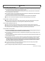
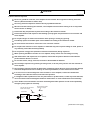
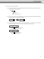
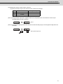
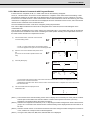
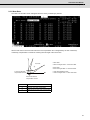
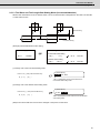
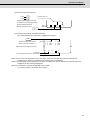
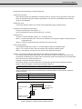
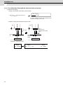
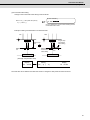
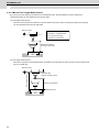
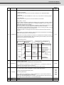
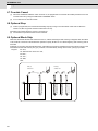
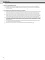
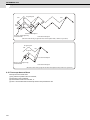
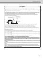
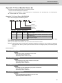
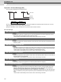
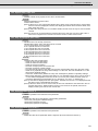
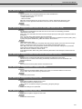
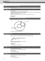
If a dangerous state is predicted in case of a power failure or product failure, in order to prevent that state,
use a servomotor with electromagnetic brakes for maintenance or mount a brake mechanism externally.
Use a double circuit construction so that the electromagnetic brake operation circuit can be operated by
emergency stop signals set externally.
Shut off with the servomotor
brake control output.
Shut off with NC brake
control PLC output.
EMG
Servomotor
MBR
Magnetic
brake
24VDC
[Continued on next page]
CAUTION
[Continued]
If an error occurs, remove the cause, secure the safety and then resume operation after alarm release.
The unit may suddenly restart after a power failure is restored, so do not go near the machine.
(Design the machine so that personal safety can be ensured even if the machine restarts suddenly.)
Confirm and adjust the program and each parameter before operation. Unpredictable movements may
occur depending on the machine.
Extreme adjustments and changes may lead to unstable operation, so never make them.
Do not apply a voltage other than that specified in the instruction manual on any terminal. Doing so may
lead to destruction or damage.
Do not mistake the terminal connections, as this may lead to destruction or damage.
Do not mistake the polarity (+ / -), as this may lead to destruction or damage.
10. Items related to servo/spindle parameters
Do not make remarkable adjustments or changes of the parameters as the operation may became unstable
Treatment of waste
The following two laws will apply when disposing of this product. Considerations must be made to each law.
The following laws are in effect in Japan. Thus, when using this product overseas, the local laws will have a
priority. If necessary, indicate or notify these laws to the final user of the product.
(1) Requirements for "Law for Promotion of Effective Utilization of Resources"
(a) Recycle as much of this product as possible when finished with use.
(b) When recycling, often parts are sorted into steel scraps and electric parts, etc., and sold to scrap
contractors. Mitsubishi recommends sorting the product and selling the members to appropriate
contractors.
(2) Requirements for "Law for Treatment of Waste and Cleaning"
(a) Mitsubishi recommends recycling and selling the product when no longer needed according to item
(1) above. The user should make an effort to reduce waste in this manner.
(b) When disposing a product that cannot be resold, it shall be treated as a waste product.
(c) The treatment of industrial waste must be commissioned to a licensed industrial waste treatment
contractor, and appropriate measures, including a manifest control, must be taken.
(d) Batteries correspond to "primary batteries", and must be disposed of according to local disposal
laws.
Disposal
(Note)
This symbol mark is for EU countries only.
This symbol mark is according to the directive 2006/66/EC Article 20 Information for endusers and Annex II.
Your MITSUBISHI ELECTRIC product is designed and manufactured with high quality materials and
components which can be recycled and/or reused.
This symbol means that batteries and accumulators, at their end-of-life, should be disposed of
separately from your household waste.
If a chemical symbol is printed beneath the symbol shown above, this chemical symbol means that the
battery or accumulator contains a heavy metal at a certain concentration. This will be indicated as
follows:
Hg: mercury (0,0005%), Cd: cadmium (0,002%), Pb: lead (0,004%)
In the European Union there are separate collection systems for used batteries and accumulators.
Please, dispose of batteries and accumulators correctly at your local community waste collection/
recycling centre.
Please, help us to conserve the environment we live in!
Trademarks
MELDAS, MELSEC, EZSocket, EZMotion, iQ Platform, MELSOFT, GOT, CC-Link, CC-Link/LT and CC-Link
IE are either trademarks or registered trademarks of Mitsubishi Electric Corporation in Japan and/or other
countries.
Ethernet is a registered trademark of Xerox Corporation in the United States and/or other countries.
Microsoft® and Windows® are either trademarks or registered trademarks of Microsoft Corporation in the
United States and/or other countries.
CompactFlash and CF are either trademarks or registered trademarks of SanDisk Corporation in the United
States and/or other countries.
Other company and product names that appear in this manual are trademarks or registered trademarks of the
respective companies.
本製品の取扱いについて
( 日本語 /Japanese)
本製品は工業用 ( クラス A) 電磁環境適合機器です。販売者あるいは使用者はこの点に注意し、住商業環境以外で
の使用をお願いいたします。
Handling of our product
(English)
This is a class A product. In a domestic environment this product may cause radio interference in which case the
user may be required to take adequate measures.
본 제품의 취급에 대해서
( 한국어 /Korean)
이 기기는 업무용 (A 급 ) 전자파적합기기로서 판매자 또는 사용자는 이 점을 주의하시기 바라며 가정외의 지역에
서 사용하는 것을 목적으로 합니다 .
CONTENTS
I SCREEN OPERATIONS................................................................................................... 1
1 Setting and Display Unit.............................................................................................................................. 3
1.1 Graphic Operation Terminal (GOT) ....................................................................................................................... 4
1.2 Screen Operation of GOT ....................................................................................................................................... 5
2 CNC Monitor Screen .................................................................................................................................... 7
2.1 Setting and Display Unit Operation..................................................................................................................... 10
2.1.1 Display Area of NC Screens ........................................................................................................................ 10
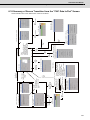
2.1.2 Screen Transition Diagram (L system)....................................................................................................... 12
2.1.3 Screen Transition Diagram (M system) ...................................................................................................... 13
2.1.4 Screen Selection Procedure........................................................................................................................ 14
2.1.5 Data Setting Method..................................................................................................................................... 18
2.2 Monitor ................................................................................................................................................................... 22
2.2.1 Position ......................................................................................................................................................... 23
2.2.1.1 Position Display Counter Zero and Origin Zero ............................................................................... 24
2.2.1.2 Manual Numerical Value Command (S, T, M).................................................................................... 25
2.2.1.3 Displaying Automatic Operation Program ........................................................................................ 29
2.2.2 Coordinate .................................................................................................................................................... 30
2.2.3 Command ...................................................................................................................................................... 31
2.2.3.1 Execution Program Monitor................................................................................................................ 31
2.2.3.2 Execution Modal Monitor .................................................................................................................... 32
2.2.3.3 Total Integrating Time Display ........................................................................................................... 33
2.2.4 Program Search............................................................................................................................................ 35
2.2.4.1 Memory Search .................................................................................................................................... 36
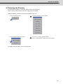
2.2.5 Program Restart ........................................................................................................................................... 37
2.2.5.1 Operation Sequences for Program Restart....................................................................................... 38
2.2.5.2 Restart Search Operations ................................................................................................................. 41
2.2.5.3 Restart Position Return System......................................................................................................... 43
2.2.5.4 Manual Numeric Commands with Program Restart ......................................................................... 45
2.2.5.5 Precautions .......................................................................................................................................... 46
2.2.6 Common Variables ....................................................................................................................................... 47
2.2.6.1 Common Variable Display .................................................................................................................. 48
2.2.6.2 Common Variable Setting ................................................................................................................... 49
2.2.6.3 Common Variable Data Deleting ........................................................................................................ 49
2.2.7 Local Variable ............................................................................................................................................... 50
2.2.7.1 Local Variable Data Display................................................................................................................ 51
2.3 Tool Offset (L system) .......................................................................................................................................... 52
2.3.1 Wear Data ...................................................................................................................................................... 53
2.3.1.1 Setting Tool Offset Data...................................................................................................................... 54
2.3.1.2 Erasing the Tool Offset Data .............................................................................................................. 54
2.3.1.3 Tool Wear and Tool Length Data Setting Mode (incremental/absolute)......................................... 55
2.3.2 Tool Length Data .......................................................................................................................................... 56
2.3.2.1 Manual Tool Length Measurement I................................................................................................... 57
2.3.2.2 Manual Numerical Command Operation on the TOOL DATA Screen (M, T) .................................. 63
2.3.2.3 Tool Presetter....................................................................................................................................... 64
2.3.3 Tool Nose Data ............................................................................................................................................. 69
2.3.4 Tool Life Management I ("#1096 T_L type" is 1) ........................................................................................ 70
2.3.4.1 Tool Life Management Method ........................................................................................................... 71
2.3.4.2 Conditions for Counting (incrementing) ........................................................................................... 72
2.3.4.3 Setting Tool Life Management Data................................................................................................... 72
2.3.4.4 Erasing Tool Life Management Data in Display Screen Units......................................................... 72
2.3.4.5 Cautions ............................................................................................................................................... 72
2.3.5 Tool Life Management II ("#1096 T_Ltype" is 2) ........................................................................................ 73
2.3.5.1 Group Registration .............................................................................................................................. 74
2.3.5.2 Tool Life Incrementation Methods ..................................................................................................... 77
2.3.5.3 Parameters ........................................................................................................................................... 78
2.3.6 Tool Registration .......................................................................................................................................... 79
2.3.6.1 Function Outline .................................................................................................................................. 79
2.3.6.2 Tool Registration in the Magazine Pot............................................................................................... 80
2.3.6.3 Tool Registration in the Spindle, Standby and Indexing Areas ...................................................... 81
2.3.6.4 Deleting Tool Registration Data ......................................................................................................... 81
2.3.6.5 Manual Numerical Command Operation on the TOOL REGISTRATION Screen (M, T) ................. 82
2.3.7 Workpiece Coordinate ................................................................................................................................. 82
2.4 Tool Offset (M system) ......................................................................................................................................... 83
2.4.1 Tool Offset .................................................................................................................................................... 84
2.4.1.1 Tool Offset Data Setting ..................................................................................................................... 85
2.4.1.2 Tool Offset Data Clear......................................................................................................................... 85
2.4.1.3 Tool Offset Data Setting Modes (Absolute and Incremental).......................................................... 86
2.4.1.4 Manual Tool Length Measurement .................................................................................................... 88
2.4.1.5 Manual Numerical Command Operation on the TOOL OFFSET Screen (M, T).............................. 91
2.4.2 Tool Registration.......................................................................................................................................... 92
2.4.2.1 Function outline .................................................................................................................................. 92
2.4.2.2 Tool Registration in the Magazine Pot .............................................................................................. 93
2.4.2.3 Tool Registration in HEAD, NEXT, and INDEX.................................................................................. 94
2.4.2.4 Deleting Tool Registration Data ......................................................................................................... 94
2.4.2.5 Manual Numerical Command Operation on the TOOL REGISTRATION Screen (M, T)................. 95
2.4.3 Tool Life ........................................................................................................................................................ 96
2.4.3.1 Function Outline .................................................................................................................................. 96
2.4.3.2 TOOL LIFE Screen Data Display ........................................................................................................ 97
2.4.3.3 TOOL LIFE Data Display and Setting (TOOL LIFE Data Screen Page 2) ...................................... 100
2.4.3.4 Clear of All TOOL LIFE Data (HEAD, NEXT, GROUP LIST Screen Page 1) .................................. 101
2.4.4 Workpiece Coordinate ............................................................................................................................... 102
2.4.4.1 Setting Workpiece Coordinate System Offset Data ....................................................................... 103
2.4.4.2 Setting External Workpiece Coordinate System Offset Data ........................................................ 103
2.4.4.3 Displaying Machine Position Data ................................................................................................... 103
2.5 Parameters .......................................................................................................................................................... 104
2.5.1 Machining Parameters............................................................................................................................... 106
2.5.1.1 Process Parameters .......................................................................................................................... 106
2.5.1.2 Control Parameters ........................................................................................................................... 106
2.5.1.3 Axis Parameters ................................................................................................................................ 107
2.5.1.4 Barrier Data ........................................................................................................................................ 107
2.5.2 Setup Parameters....................................................................................................................................... 108
2.6 Program ............................................................................................................................................................... 109
2.6.1 Function Outline......................................................................................................................................... 110
2.6.2 Edit Type ..................................................................................................................................................... 110
2.6.3 Menu Function............................................................................................................................................ 111
2.6.3.1 MDI Screen Menu Function .............................................................................................................. 112
2.6.3.2 EDIT Screen Menu Function............................................................................................................. 115
2.6.4 Program Edit Operation............................................................................................................................. 119
2.6.4.1 Common Operation Between Screen Editing and Word Editing .................................................. 120
2.6.4.2 Screen Editing ................................................................................................................................... 123
2.6.4.3 Word Editing ...................................................................................................................................... 128
2.6.5 MDI Screen Extension Operation ............................................................................................................. 149
2.6.5.1 MDI Data Registration in Memory .................................................................................................... 149
2.6.6 Edit Screen Extension Operation ............................................................................................................. 150
2.6.6.1 Edit Data Call ..................................................................................................................................... 150
2.6.6.2 New Program Registration and Preparation ................................................................................... 154
2.7 Data In/Out........................................................................................................................................................... 155
2.7.1 Program Erase............................................................................................................................................ 156
2.7.2 Program File ............................................................................................................................................... 160
2.7.3 Program Copy ............................................................................................................................................ 161
2.7.3.1 Machining Program Copy ................................................................................................................. 162
2.7.3.2 Machining Program Condense ........................................................................................................ 162
2.7.3.3 Machining Program Merge ............................................................................................................... 163
2.7.3.4 Changing the Machining Program Number .................................................................................... 164
2.8 Diagnosis............................................................................................................................................................. 165
2.8.1 Alarm Message........................................................................................................................................... 166
2.8.1.1 Tracing of Alarm and Stop Codes ................................................................................................... 167
2.8.2 Servo Monitor ............................................................................................................................................. 168
2.8.2.1 Servo Monitor .................................................................................................................................... 168
2.8.2.2 Servo Diagnosis ................................................................................................................................ 170
2.8.2.3 Power Supply Diagnosis .................................................................................................................. 171
2.8.2.4 Synchronous Error............................................................................................................................ 172
2.8.3 Spindle Monitor .......................................................................................................................................... 173
2.8.3.1 Spindle Monitor ................................................................................................................................. 173
2.8.3.2 Spindle Diagnosis ............................................................................................................................. 176
2.8.4 PLC Interface Diagnosis of CNC CPU ...................................................................................................... 177
2.8.4.1 PLC-I/F Setting and Display ............................................................................................................. 178
2.8.4.2 PLC Device Data Display .................................................................................................................. 181
2.8.4.3 PLC Interface Signal Forcible Definition (Single-shot Type) ......................................................... 182
2.8.4.4 PLC Interface Signal Forcible Definition (Modal Type) .................................................................. 183
2.8.4.5 Diagnosis Executed When an Emergency Stop Status Occurs.................................................... 184
2.8.5 Absolute Position Monitor......................................................................................................................... 185
2.8.5.1 ABS Servo Monitor ............................................................................................................................ 185
2.8.5.2 Absolute Position Initialization ........................................................................................................ 186
2.8.6 PLC Axis Monitor ....................................................................................................................................... 188
2.8.7 Operation History ....................................................................................................................................... 189
2.8.7.1 Diagnosis of Operation History and the Occurrence Time of History (History Data) ................. 190
2.8.7.2 Correspondence of Operation Keys and Key History.................................................................... 191
2.8.7.3 Input/Output Signal History Covering Range ................................................................................. 192
2.8.7.4 Suspending the Operation History Function .................................................................................. 193
2.8.7.5 Saving the Operation History Data .................................................................................................. 193
2.8.7.6 Switching the History Display .......................................................................................................... 194
2.8.7.7 Clearing the Operation History and the Occurrence Time of History (History Data) .................. 194
2.8.7.8 Setting and Displaying the Time and Date of Occurrence of Operation History Data ................ 194
2.8.7.9 Outputting the Storage Data for Operation History........................................................................ 195
2.8.7.10 Precautions ...................................................................................................................................... 196
2.8.8 System Configuration ................................................................................................................................ 197
2.8.8.1 S/W Module Tree (NC System) ......................................................................................................... 197
2.8.8.2 S/W Module Tree(2) (Drive Unit) ....................................................................................................... 197
2.8.8.3 H/W Monitor........................................................................................................................................ 198
2.8.8.4 Option ................................................................................................................................................. 198
2.8.9 NC Data Sampling ...................................................................................................................................... 199
2.8.9.1 Display Items...................................................................................................................................... 200
2.8.9.2 Parameters ......................................................................................................................................... 201
2.8.9.3 Address Designation......................................................................................................................... 205
2.8.9.4 Data Output Format ........................................................................................................................... 211
2.8.9.5 How to Use the Data Sampling before a Trigger ............................................................................ 213
2.8.9.6 Outputting the Data ........................................................................................................................... 214
2.8.9.7 Flow of the Operation........................................................................................................................ 215
II MACHINE OPERATIONS ............................................................................................ 217
1 Operation State ........................................................................................................................................ 221
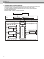
1.1 Operation State Transition Diagram.................................................................................................................. 222
1.2 Power OFF ........................................................................................................................................................... 223
1.3 Not Ready ............................................................................................................................................................ 223
1.4 Ready ................................................................................................................................................................... 224
1.4.1 Reset............................................................................................................................................................ 224
1.4.2 Automatic Operation Start......................................................................................................................... 224
1.4.3 Automatic Operation Pause ...................................................................................................................... 224
1.4.4 Automatic Operation Stop ......................................................................................................................... 224
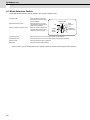
2 Indicator Lamps ....................................................................................................................................... 225
2.1 NC Unit Ready ..................................................................................................................................................... 226
2.2 Automatic Operation Busy................................................................................................................................. 226
2.3 Automatic Operation Start Busy........................................................................................................................ 226
2.4 Automatic Operation Pause Busy ..................................................................................................................... 226
2.5 Return to Reference Point.................................................................................................................................. 226
2.6 NC Alarm.............................................................................................................................................................. 226
2.7 M00 ....................................................................................................................................................................... 226
2.8 M02/M30 ............................................................................................................................................................... 226
3 Reset Switch and Emergency Stop Button ........................................................................................... 227
3.1 Reset Switch........................................................................................................................................................ 228
3.2 Emergency Stop Button ..................................................................................................................................... 228
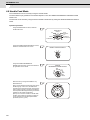
4 Operation Mode........................................................................................................................................ 229
4.1 Mode Selection Switch ....................................................................................................................................... 230
4.2 Jog Feed Mode .................................................................................................................................................... 231
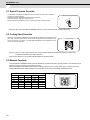
4.3 Rapid Traverse Feed Mode ................................................................................................................................ 232
4.4 Return to Reference Position Mode .................................................................................................................. 233
4.5 Incremental Feed Mode ...................................................................................................................................... 235
4.6 Handle Feed Mode .............................................................................................................................................. 236
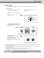
4.7 Memory Mode...................................................................................................................................................... 237
4.8 MDI Operation Mode........................................................................................................................................... 238
5 Operation Panel Switches in Operation Mode ...................................................................................... 239
5.1 Rapid Traverse Override .................................................................................................................................... 240
5.2 Cutting Feed Override ........................................................................................................................................ 240
5.3 Manual Feedrate ................................................................................................................................................. 240
5.4 Handle/Incremental Feed Magnification Factor ............................................................................................... 241
5.5 Handle Feed Axis Selection............................................................................................................................... 241
5.6 Manual Pulse Generator..................................................................................................................................... 241
5.7 Cycle Start and Feed Hold ................................................................................................................................. 242
5.8 Feed Axis Selection............................................................................................................................................ 242
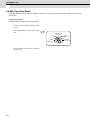
6 Operation Panel Switch Functions......................................................................................................... 243
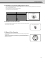
6.1 All Axes Machine Lock....................................................................................................................................... 244
6.2 Chamfering (L system)....................................................................................................................................... 244
6.3 Miscellaneous Function Lock............................................................................................................................ 245
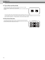
6.4 Single Block ........................................................................................................................................................ 245
6.5 Dry Run................................................................................................................................................................ 245
6.6 Manual Override.................................................................................................................................................. 245
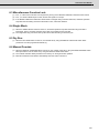
6.7 Override Cancel .................................................................................................................................................. 246
6.8 Optional Stop ...................................................................................................................................................... 246
6.9 Optional Block Skip............................................................................................................................................ 246
6.10 Manual Absolute ............................................................................................................................................... 247
6.11 Error Detect ....................................................................................................................................................... 248
6.12 Follow-up Function........................................................................................................................................... 248
6.13 Axis Removal .................................................................................................................................................... 248
6.14 Manual/Automatic Synchronous Feed ........................................................................................................... 248
6.15 Handle Interruption........................................................................................................................................... 249
6.15.1 Outline....................................................................................................................................................... 249
6.15.2 Interruptible Conditions .......................................................................................................................... 249
6.15.3 Interruption Effective Axis ...................................................................................................................... 250
6.15.4 Axis Movement Speed Resulting from Interruption ............................................................................. 250
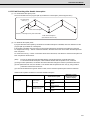
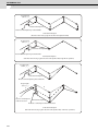
6.15.5 Path Resulting After Handle Interruption .............................................................................................. 251
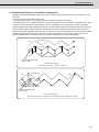
6.15.6 Handle Interruption in Tool Radius Compensation .............................................................................. 253
6.15.7 Interrupt Amount Reset ........................................................................................................................... 254
6.15.8 Operation Sequence ................................................................................................................................ 255
III MAINTENANCE ........................................................................................................... 257
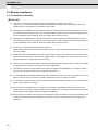
1 Maintenance Works ................................................................................................................................. 261
1.1 Instruction of Inspection Works ........................................................................................................................ 262
2 Daily Inspection........................................................................................................................................ 265
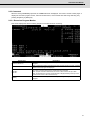
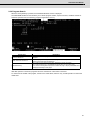
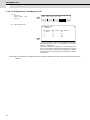
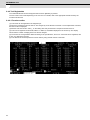
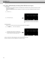
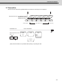
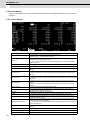
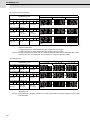
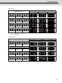
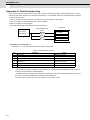
3 Display on 7-segment LED...................................................................................................................... 267
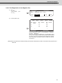
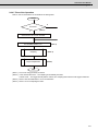
3.1 Initial Settings ..................................................................................................................................................... 269
3.1.1 Flow of Initializing CNC CPU Unit............................................................................................................. 269
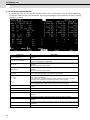
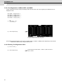
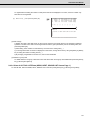
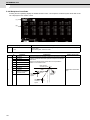
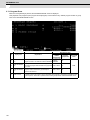
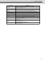
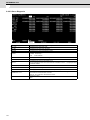
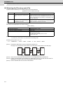
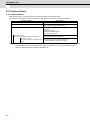
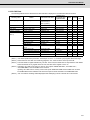
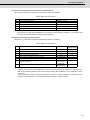
3.2 Alarm/Stop codes ............................................................................................................................................... 270
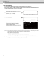
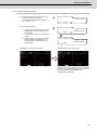
3.2.1 Detailed Display of Alarm/Stop Codes..................................................................................................... 270
3.2.2 Notes ........................................................................................................................................................... 271
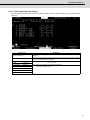
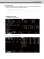
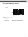
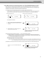
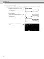
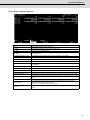
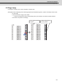
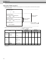
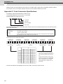
3.2.3 Examples of LED Display .......................................................................................................................... 274
4 Periodic Inspection .................................................................................................................................. 281
5 Hardware Replacement Methods............................................................................................................ 283
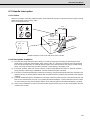
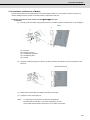
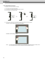
5.1 Module Installation ............................................................................................................................................. 284
5.1.1 Instructions for Handling .......................................................................................................................... 284
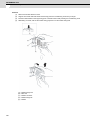
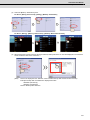
5.1.2 Installation and Removal of Module......................................................................................................... 285
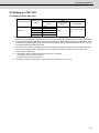
5.2 Battery for CNC CPU .......................................................................................................................................... 287
5.2.1 Battery Life for CNC CPU .......................................................................................................................... 287
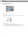
5.2.2 CNC CPU Battery Replacement Procedure ............................................................................................. 288
5.3 Battery inside PLC CPU ..................................................................................................................................... 289
5.3.1 Battery Life ................................................................................................................................................. 289
5.3.2 Replacement Procedure for Battery inside PLC CPU ............................................................................. 295
6 CNC Data Input/Output ............................................................................................................................ 297
6.1 Screen Transition to the "CNC Data In/Out" Screen........................................................................................ 298
6.2 Setting Communication...................................................................................................................................... 299
6.3 "CNC Data In/Out" Screen Display .................................................................................................................... 302
6.4 Operation Windows ............................................................................................................................................ 305
6.4.1 Function Selection Window ...................................................................................................................... 305
6.4.2 Device Selection Window .......................................................................................................................... 305
6.4.3 CNC Data Selection Window ..................................................................................................................... 306
6.4.4 Copy Confirmation Window ...................................................................................................................... 306
6.4.5 Overwrite Confirmation Window............................................................................................................... 307
6.4.6 Comparison Error Detail Window ............................................................................................................. 308
6.4.7 Delete Confirmation Window .................................................................................................................... 309
6.4.8 Key Window ................................................................................................................................................ 310
6.5 Selecting the Function........................................................................................................................................ 311
6.6 Selecting the Device ........................................................................................................................................... 312
6.7 Selecting the Directory ....................................................................................................................................... 313
6.8 Selecting the Directory and a File ..................................................................................................................... 314
6.9 Page Jump ........................................................................................................................................................... 315
6.10 Switch between File Information Items to Display......................................................................................... 316
6.11 Copying a File.................................................................................................................................................... 317
6.11.1 Copying Any File Other than the SRAM.BIN File................................................................................... 317
6.12 Comparing Files ................................................................................................................................................ 319
6.13 Deleting Files..................................................................................................................................................... 321
6.14 Refreshing the List............................................................................................................................................ 324
6.15 Stop the USB Drive (For GT16 Only) ............................................................................................................... 325
6.16 Creating a Directory.......................................................................................................................................... 326
6.17 Changing a File Name when Outputting the File ........................................................................................... 327
6.18 Summary of Screen Transition from the "CNC Data In/Out" Screen ........................................................... 329
6.19 Various Status ................................................................................................................................................... 330
6.19.1 Data Protection......................................................................................................................................... 330
6.19.2 CNC Data................................................................................................................................................... 331
6.19.3 Messages .................................................................................................................................................. 333
6.19.4 Parameters................................................................................................................................................ 337
6.19.5 Signals....................................................................................................................................................... 337
6.20 Restrictions ....................................................................................................................................................... 338
7 Data Backup and Restoration ................................................................................................................. 339
7.1 GOT Data Backup and Reinstallation................................................................................................................ 340
7.1.1 Backup Procedures.................................................................................................................................... 340
7.1.2 Reinstallation Procedures ......................................................................................................................... 342
7.2 PLC/CNC CPU Data Backup and Restoration .................................................................................................. 344
7.2.1 Data Backup................................................................................................................................................ 345
7.2.1.1 Backup Procedures ........................................................................................................................... 345
7.2.1.2 Backup Files Structure...................................................................................................................... 348
7.2.2 Data Restoration......................................................................................................................................... 349
7.2.2.1 Restoration Procedures .................................................................................................................... 350
IV APPENDIXES .............................................................................................................. 355
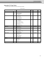
Appendix 1 Registering and Editing Fixed Cycle Programs................................................................... 357
Appendix 1.1 Parameter for Fixed Cycle Operation .............................................................................................. 358
Appendix 1.2 Inputting a Fixed Cycle Program...................................................................................................... 358
Appendix 1.3 Outputting a Fixed Cycle Program................................................................................................... 358
Appendix 1.4 Deleting a Fixed Cycle Program....................................................................................................... 358
Appendix 1.5 Standard Fixed Cycle Subprogram.................................................................................................. 359
Appendix 2 List of Function Codes........................................................................................................... 371
Appendix 3 List of Command Value Ranges............................................................................................ 373
Appendix 4 Data Protection ....................................................................................................................... 375
Appendix 4.1 Data Protection Key........................................................................................................................... 376
Appendix 4.2 Edit Lock B, C .................................................................................................................................... 378
Appendix 5 Table of Conversion Codes for Error Code Output ............................................................. 379
Appendix 5.1 Code Conversion Specifications ..................................................................................................... 380
Appendix 5.2 Code Table ......................................................................................................................................... 381
Appendix 5.3 Restrictions........................................................................................................................................ 382
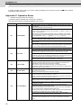
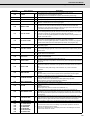
Appendix 6 Operation Messages on Setting Display Unit ...................................................................... 383
Appendix 6.1 Operation Errors................................................................................................................................ 384
Appendix 6.2 Operator Messages ........................................................................................................................... 388
Appendix 7 Explanation of Alarms............................................................................................................ 391
Appendix 7.1 Operation Errors (M) ......................................................................................................................... 392
Appendix 7.2 Stop Codes (T)................................................................................................................................... 400
Appendix 7.3 Servo/Spindle Alarms (S) ................................................................................................................. 405
Appendix 7.3.1 Servo Errors (S01/S03/S04) ..................................................................................................... 405
Appendix 7.3.2 Initial Parameter Errors (S02) .................................................................................................. 420
Appendix 7.3.3 Safety Function Errors (S05) ................................................................................................... 420
Appendix 7.3.4 Parameter Errors (S51)............................................................................................................. 421
Appendix 7.3.5 Servo Warnings (S52)............................................................................................................... 422
Appendix 7.3.6 Safety Function Warnings (S53).............................................................................................. 424
Appendix 7.4 MCP Alarms (Y) ................................................................................................................................. 425
Appendix 7.5 Safety Observation Alarms (Y)......................................................................................................... 434
Appendix 7.5.1 Safety Observation Alarms...................................................................................................... 434
Appendix 7.5.2 Safety Observation Warnings.................................................................................................. 443
Appendix 7.6 System Alarms (Z)............................................................................................................................. 445
Appendix 7.7 Absolute Position Detection System Alarms (Z7*) ........................................................................ 450
Appendix 7.8 Emergency Stop Alarms (EMG) ....................................................................................................... 454
Appendix 7.9 Auxiliary Axis Operation Errors (M) ................................................................................................ 457
Appendix 7.10 CNCCPU-side Safety Sequence Alarm(U)..................................................................................... 459
Appendix 7.11 Multi CPU Errors (A)........................................................................................................................ 460
Appendix 7.12 Network Errors (L) ........................................................................................................................... 486
Appendix 7.13 Program Errors (P) .......................................................................................................................... 494
Appendix 7.14 CNC CPU Module System Alarms ................................................................................................. 514
Appendix 8 User Parameters ..................................................................................................................... 515
I SCREEN OPERATIONS
1
MITSUBISHI CNC
2
1
Setting and Display Unit
3
MITSUBISHI CNC
1 Setting and Display Unit
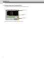
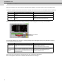
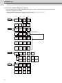
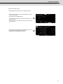
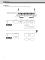
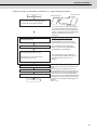
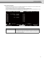
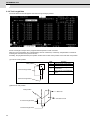
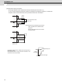
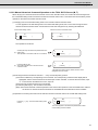
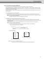
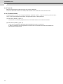
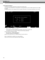
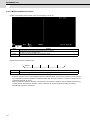
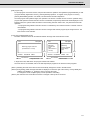
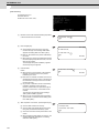
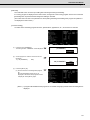
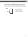
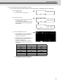
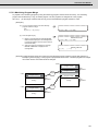
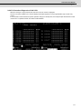
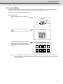
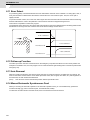
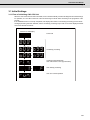
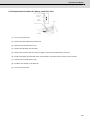
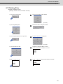
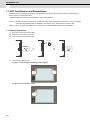
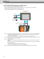
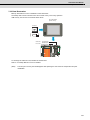
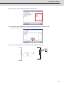
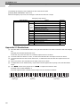
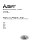
1.1 Graphic Operation Terminal (GOT)
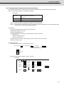
An NC operation screen and an NC keyboard shown below are displayed on GOT.
Function switch
keys
NC operation
screen
NC keyboard
This screen is dedicated for NC operation and its size is fixed.
4
C70 Instruction Manual
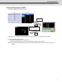
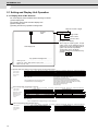
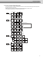
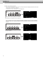
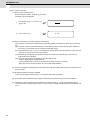
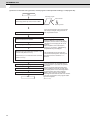
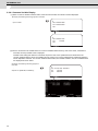
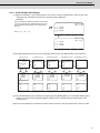
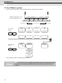
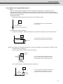
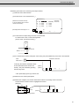
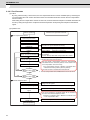
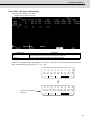
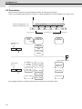
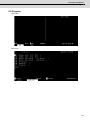
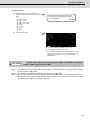
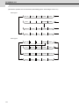
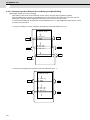
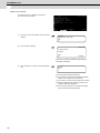
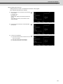
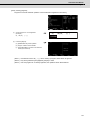
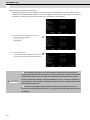
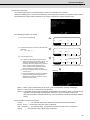
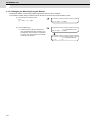
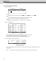
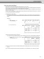
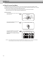
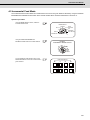
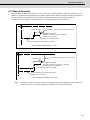
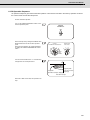
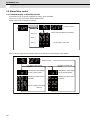
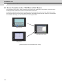
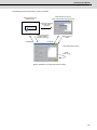
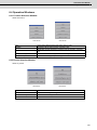
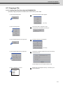
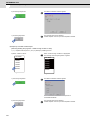
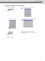
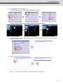
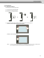
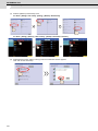
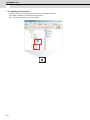
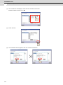
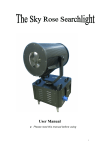
1.2 Screen Operation of GOT
1.2 Screen Operation of GOT
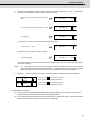
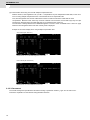
Using GOT enables the NC screen as follows.
<GT15>
<GT16>
"CNC Monitor"
icon
(a)
Exit
Monitor screen
Extended function switch
(to CNC monitor)
(Note 1)
Extended function switch
(to CNC monitor)
(b)
Exit
(Note) Refer to "2.1.2 Screen Transition Diagram (L system)" (Refer to 2.1.3 for M system.) for details.
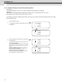
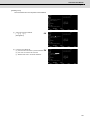
NC screen appears by either method.
(a) Select "CNC monitor" key on Utility screen.
(b) Select the extended function switch (to CNC Monitor) on Monitor screen. (Note 1)
(Note 1) This switch differs depending on the machine. Refer to the instruction manual issued by the machine tool
builder.
5
MITSUBISHI CNC
1 Setting and Display Unit
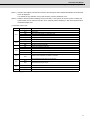
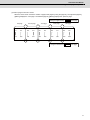
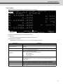
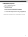
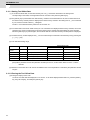
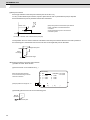
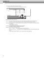
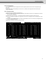
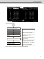
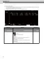
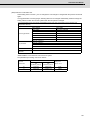
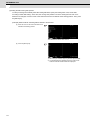
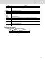
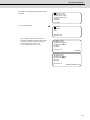
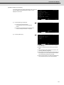
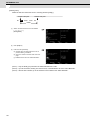
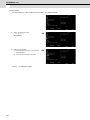
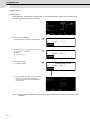
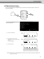
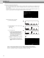
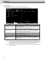
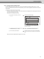
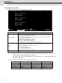
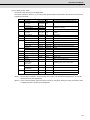
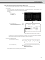
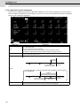
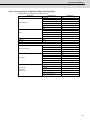
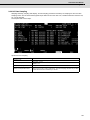
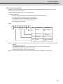
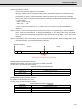
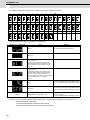
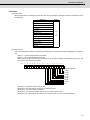
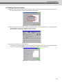
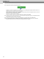
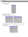
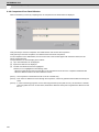
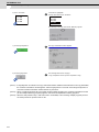
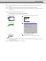
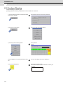
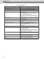
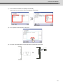
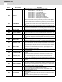
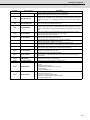
When NC monitor function cannot work, NC data will not be displayed. Touch the screen to return to the Utility screen.
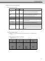
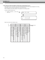
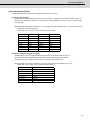
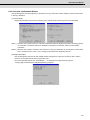
List of error messages (If more than one error are occurring at the same time, the error with higher priority is displayed.)
Priority
High
Middle
Low
Error message
Remedy
E71 communication driver is not installed. (NC
monitor)
Install E71 communication driver.
Monitor data not found. (NC monitor)
Download the NC screen data (special module
screen).
The IP address of NC to monitor is not set up. (NC Set the IP address by the drawing S/W (Ethernet
monitor)
setting), and download the monitor data.
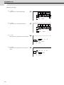
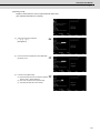
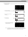
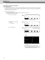
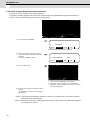
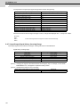
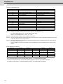
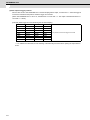
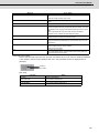
When a communication error occurs during monitoring, the error disappears at recovery of communication.
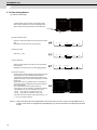
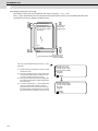
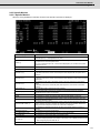
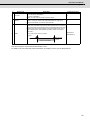
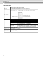
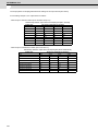
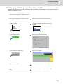
Communication
error
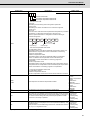
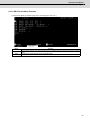
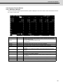
In the message display area, the alarm or warning message that has the highest priority among the alarms currently
occurs under the current part system.
Message
Communication
error
Details of message
An error has occurred in the communication with
the NC.
Remedy
- Check the connection between the NC and GOT.
(Cable connection, noise, etc.)
- Check the NC and GOT network settings.
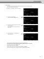
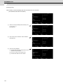
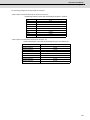
The NC-dedicated display unit or display unit other
than touch panel is connected, and key inputs from The key inputs become valid by following operations.
KEY OPERATION
the menu section or keyboard section are invalid. - Disconnect the NC-dedicated display unit.
INVALID
Inputs from the display unit other than touch panel - Press the OPERATE menu.
are valid in this case.
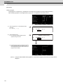
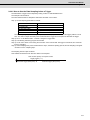
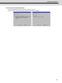
When some error occurs with the communication with NC, a dialogue box will appear.
Refer to the appendix written later for details of the other alarms or messages.
6
2
CNC Monitor Screen
7
MITSUBISHI CNC
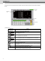
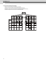
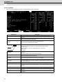
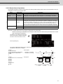
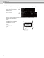
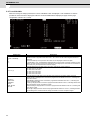
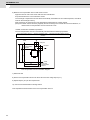
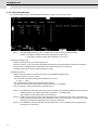
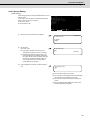
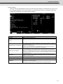
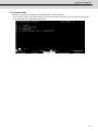
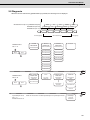
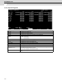
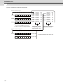
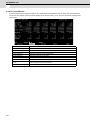
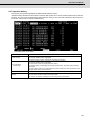
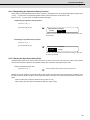
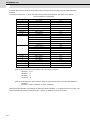
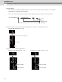
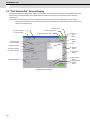
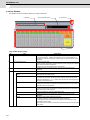
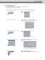
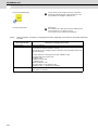
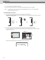
2 CNC Monitor Screen
In this screen, the various information which is needed to setup and maintain the machine and NC system is displayed
and set.
2. Function
switch
1. NC screen
area
3. Menu
4. Key board
(1) Display Items
Display item
Details
1. NC screen area
The functions such as position monitoring, alarm diagnosis, tool offset/parameters, and program
edit.
2. Function switch
The following keys used to select the display function.
MONITOR
Selects position monitoring function.
Refer to "2.2 Monitor".
DIAGN
IN/OUT
Selects alarm diagnosis function or data input/output function.
Refer to "2.8 Diagnosis" and "2.7 Data In/Out.
TOOL
PARAM
Selects tool offset function and parameter setting.
Refer to "2.3 Tool Offset (L system)", "2.4 Tool Offset (M system)" and "2.5 Parameters".
EDIT
MDI
Selects program edit function.
Refer to "2.6 Program".
3. Menu
MENU 1 to 5
Changes a screen according to menu.
If the NC-dedicated display is valid, the "KEY OPERATION INVALID" message and [OPERATE]
menu will appear.
Select this menu when operating the keys on the GOT.
BACK
Displays the previous page if there are multiple pages in a screen.
NEXT
Displays the next page if there are multiple pages in a screen.
Keyboard
8
This is used to set a data in NC screens.
Refer to "(2) Composition of displayed keyboard" for details.
C70 Instruction Manual
(2) Composition of displayed keyboard
Composition of the displayed keyboard is shown below.
Data setting keys
Special keys
Key type
Keys
...
A
Z
!
#
1
Function
2
$
3
4
5
9
0
6
Data setting keys
(
7
)
8
=
[
-
+
]
*
SP
These keys are used to set alphabetic characters (only capital
letters), numbers, space, and symbols, etc.
The characters in gray can be set after touching [SHIFT] key.
,
/
.
Moves a cursor up/down/left/right. (Repeat function is
available)
Moves a cursor one block forward/backward. (Repeat function
is available)
DEL
Deletes a character at the cursor.
INS
Switches between insertion/overwrite modes.
CAN
C.B
Deletes one block at the cursor while a machining program is
edited.
Touching [C.B CAN] key after [SHIFT] key deletes all blocks
displayed in the screen.
EOB
Adds EOB (;) code in the editing machining program.
Special keys
INPUT
SHIFT
Fixes the setting.
Changes the key function.
9
MITSUBISHI CNC
2 CNC Monitor Screen
2.1 Setting and Display Unit Operation
2.1.1 Display Area of NC Screens
NC screen display area is divided into the following four areas:
(1) Data display area
(2) Operation status mode and alarm display area
(3) Menu display area
(4) Setting area and key operation message area
Maximum number of pages
…… Function
name
1
……
MONITOR
3. 1/4
Page number
Menu number
Function name
Part system name display
When using the 2-part sysytem, the part
system name will be displayed here for
screens that can be set and displayed per
system. The name set in parameter
“#1169 system name” will display.
The part systems can be switched over by
pressing SHIFT $
.
Data display area
4
Key operation message area…………
……6HWWLQJDUHD……………………………………………………
……2SHUDWLRQVWDWXVPRGHDODUPGLVSOD\DUHD…………………
……0HQXGLVSOD\DUHD………………………………………………
Operation status mode display and menu display (during normal operation) (Note 1)
1
2 3 4
ST1
㻞㻙㼜㼍㼞㼠㻌㼟㼥㼟㼠㼑㼙
ST1
㻟㻙㼜㼍㼞㼠㻌㼟㼥㼟㼠㼑㼙
㼛㼞㻌㼙㼛㼞㼑
3
↑
ST1
㻝㻙㼜㼍㼞㼠㻌㼟㼥㼟㼠㼑㼙㻌
5
6 7 8
ST2
9
10 11 12
ST3
㻔㼎㼘㼍㼚㼗㻕
ST2
13 14 15 16 17 18 19 20
ST4
ST5
$1 operation mode
ST3
ST4
21 22 23 24 25 26 27 28 29 30 31 32 33 34 35 36 37 38 39 40
ST6
ST7
ST8
$1 operation mode
2
ST5
㻼㼍㼞㼠㻌㼟㼥㼟㼠㼑㼙㻌㻺㼛㻚
ST1
ST6
$2 operation mode
㻔㼎㼘㼍㼚㼗㻕
ST7
ST8
Ope mode (arbitrary)
ST1: Operation status (EMG, RST, LSK, etc.)
ST2: Metric/Inch command (mm/in.)
ST3: Absolute/Incremental command mode (ABS/INC)
ST4: During tool radius compensation/Cancel (G40 to G42)
ST5: Workpiece coordinate system (G54 to G59, P01 to P48)
ST6: Executing subprogram. (SB1 to SB8)
ST7: Executing fixed cycle. (fix)
ST8: (Not used.)
This is displayed when 6 or more menus exist.
The selected menu is reverse-displayed.
Alarm message display (during alarm occurrence)
㻝㻙㼜㼍㼞㼠㻌㼟㼥㼟㼠㼑㼙㻌
㻞㻙㼜㼍㼞㼠㻌㼟㼥㼟㼠㼑㼙
1
2
3 4
5
6 7 8 9 10 11 12
First alarm of $1
13 14 15 16
17 18 19 20
21 22 23 24 25 26 27 28 29 30 31 32 33 34 35 36 37 38 39 40
Second alarm of $2
•㻭㼘㼍㼞㼙㻌㼍㼠㻌㻐㻝㻌㼍㼚㼐㻌㻐㻞
1
First alarm of $1
2
•㻭㼘㼍㼞㼙㻌㼍㼠㻌㼛㼚㼘㼥㻌㻐㻝
1
2
•㻭㼘㼍㼞㼙㻌㼍㼠㻌㼛㼚㼘㼥㻌㻐㻞
㻟㻙㼜㼍㼞㼠㻌㼟㼥㼟㼠㼑㼙
㼛㼞㻌㼙㼛㼞㼑
1
First alarm of $1
(blank)
ST1
$1 operation mode
First alarm of $2
ST1
2
First alarm of arbitrary part system
3
䊺
(blank)
$2 operation mode
First alarm of $2
Second alarm of arbitrary part system
㻼㼍㼞㼠㻌㼟㼥㼟㼠㼑㼙㻌㻺㼛㻚
Alarm is highlighted and message (warning) is normally displayed.
Alarm during absolute position initializing (Note 2)
1
㻝㻙㼜㼍㼞㼠㻌㼟㼥㼟㼠㼑㼙㻌
㻞㻙㼜㼍㼞㼠㻌㼟㼥㼟㼠㼑㼙
㻟㻙㼜㼍㼞㼠㻌㼟㼥㼟㼠㼑㼙
㼛㼞㻌㼙㼛㼞㼑
2
3 4
5 6 7 8 9 10 11 12 13 14 15 16
Alarm of “ absolute position initializing“
Alarm of “ absolute position initializing“
Alarm of “ absolute position initializing“
17 18 19 20
21 22 23 24 25 26 27 28 29 30 31 32 33 34 35 36 37 38 39 40
First alarm of $1
䊺
㻼㼍㼞㼠㻌㼟㼥㼟㼠㼑㼙㻌㻺㼛㻚
10
First alarm of $2
First alarm of arbitrary part system
C70 Instruction Manual
2.1 Setting and Display Unit Operation
(Note 1) When the other display units are also connected, the message as "KEY OPERATION INVAID" and OPERATE
menu are displayed.
To invalidate the key operation on the panel computer, press the OPERATE menu.
(Note 2) While the absolute position initializing is being executed in a part system, all the part systems, including the
systems which are not under the execution, show "absolute position initializing" in their each operation status
mode/alarm display area.
(1) Operation status mode
Position
ST1
ST2
ST3
ST4
ST5
ST6
ST7
Display symbol
Explanation
EMG
During emergency stop
RST
During reset
LSK
When paper tape reader is in label skip state
HLD
During feed hold stop
STP
During single block stop
___
Normal operation state other than the above
mm
Metric command
in.
ABS
Inch command
Absolute command mode G90
INC
Incremental command mode G91
G40
Tool radius compensation cancel state
G41
During tool radius compensation (left)
G42
During tool radius compensation (right)
G54
:
G59
Selection of the workpiece coordinate is indicated.
___
This indicates that subprogram is not executed.
SB1
SB2
:
Machining program execution is controlled according to subprogram data. Each value
indicates the subprogram depth.
fix
___
Fixed cycle is being executed.
Fixed cycle is not executed.
ST8
(Note 1) "_ _ _" denotes blank display.
11
MITSUBISHI CNC
2 CNC Monitor Screen
2.1.2 Screen Transition Diagram (L system)
If the multi-part system is provided, the displayed part system for screens indicated with the [$] mark will change when
the [SHIFT] and [4] keys are pressed.
All data may not fit on one page according to the number of part systems or number of axes.
Use the [BACK] and [NEXT] keys to change the page in this case.
[MENU 1]
[MENU2]
[MENU 3]
MON ITOR
C OMMAND
MODAL
INF OR M.
TIME
$
POSITION
COORDINATE
$
$
PROGRAM
SEARCH
$
COMMON
VARIABLE
RESERCH
$
$
TOOL
PARAM
[MEN U4]
$
$
T OOL T IP
OF FSET
LOCAL
VAR IABLE
$
TOOL
LIFE
DATA
N OSE-R
TOOL
DAT A
The setting can be displaye d
$
WORK
$
PROCESS
CONT ROL
AXIS
BAR RIER
when [OPEN SETU P PARAM] is selected.
OPEN
SET UP
PARAM
BASE
SPEC
PARAM
AXIS
SPEC
PARAM
SER VO
PARAM
MULTI
CPU
PAR AM
#1000
#2000
#2200
#2670 0
SPINDLE
BASE
SPEC .
PARAM
SPINDLE
SPEC.
INDEX
PAR AM
Net
PARAM
#3000
# 13000
#1280 0
#29000
MC-ER R.
C MP.
PLC
T IMER
MAC RO
F ILE
POSIT ION
SWITCH
#4000,#5000
#6000
MDI
EDIT
$
#7000, #27000
$
#7000
EDIT MD I
EDI T
MDI-ENT
MD I
EDIT
SEARC H
EDI T
PROGRAM
SMALL
LARGE
$
DIAGN
IN/OUT
ALARM
MESSAGE
SERVO MONITOR
SPIN DLE
SERVODIAGNOSIS
PS DIAGNOSIS
MONITOR
SPIN DLE
SYNCHRONOUS
DIAGN OSIS
PLC AXIS
MONIT OR
OPER ATION
S/W MODU LE
ABS SERVO
MONITOR
ABS POSITION
SET
PROGRAM
ERASE
12
PLC-I/F
HISTORY
TR EE
H/W MONITOR
OPTION
PROGRAM
FILE
PROGRAM
C OPY
N C-DAT A
SAMPLIN G
FIL E
C70 Instruction Manual
2.1 Setting and Display Unit Operation
2.1.3 Screen Transition Diagram (M system)
If the multi-part system is provided, the displayed part system for screens indicated with the [$] mark will change when
the [SHIFT] and [4] keys are pressed.
All data may not fit on one page according to the number of part systems or number of axes.
Use the [BACK] and [NEXT] keys to change the page in this case.
[MENU 1]
[MENU2]
[MENU 3]
[MEN U4]
$
$
/10+614
C OMMAND
MODAL
INF OR M.
TIME
$
POSITION
COORDINATE
$
$
PROGRAM
SEARCH
$
COMMON
VARIABLE
RESERCH
$
LOCAL
VAR IABLE
$
TOOL
PARAM
TOOL
OF FSET
TREGISTRATION
TOOL
LIFE
PROCESS
CONTR OL
AXIS
BARR IER
OPEN
SETUP
PARAM
The setting can be displaye d
$
WORK
OF FSET
$
when [OPEN SETU P PAR AM] is selected.
#8000
BASE
SPEC
PARAM
AXIS
SPEC
PAR AM
SER VO
PARAM
MULTI
CPU
PAR AM
#1000
# 2000
#2200
#26700
SPIN DLE
BASE
SPEC.
PARAM
SPIND LE
SPEC.
IND EX
PARAM
Net
PARAM
#3000
#13000
#1 2800
#29000
MC-ERR .
CMP.
PLC
TIMER
MACR O
FI LE
# 4000,#5000
#6000
$ #7 00 0,
#27000
POSITION
SWIT CH
$
#7000
EDIT MD I
MDI
EDIT
MDI-ENT
MD I
EDIT
SEARCH
EDIT
PROGRAM
SMALL
LARGE
FIL E
$
DIAGN
IN/OUT
ALARM
MESSAGE
SERVO MONITOR
SPIN DLE
SERVODIAGNOSIS
MONITOR
PS DIAGNOSIS
SPIN DLE
DIAGN OSIS
SYNCHRONOUS
S/W MOD ULE
ABS SER VO
MON ITOR
ABS POSITION
SET
PROGRAM
ERASE
PLC-I /F
PLC AXIS
MON ITOR
OPERATION
HISTORY
TREE
H/W MON ITOR
OPTION
PROGRAM
F ILE
PROGR AM
COPY
NC-D AT A
SAMPLING
13
MITSUBISHI CNC
2 CNC Monitor Screen
2.1.4 Screen Selection Procedure
Select a screen according to the following procedure:
(a) Select a function screen by using the appropriate function key.
(b) Select a menu screen in the function by using the appropriate menu key.
(c) Select a page in the menu screen by using the page key.
Function
Menu 1
Menu 2
Menu 3
Menu 4
1.1
screen
2.1
screen
3.1
screen
4.1
screen
1.2
screen
2.2
screen
MENU
Menu 1
Menu 2
Menu 3
Menu 4
5.1
screen
6.1
screen
7.1
screen
8.1
screen
5.2
screen
6.2
screen
Page
First
Page
Page
Second
Page
Third
Page
Fouth
Page
14
1.3
screen
4.2
screen
Page
6.3
screen
6.4
screen
8.2
screen
C70 Instruction Manual
2.1 Setting and Display Unit Operation
(1) Select a function screen
[MONITOR] [DIAGN IN/OUT] [TOOL PARAM] [EDIT MDI]
Press the function selection key corresponding to the function
screen to be displayed.
(Example) Press the [MONITOR] key.
1) The previously displayed menu screen is displayed in the
data display area.
2) The first display screen after power is turned on is the screen
on the first menu.
If the same function selection key is pressed again, a return is
made to the first page screen of the first menu.
(Example) Press the [MONITOR] key again.
15
MITSUBISHI CNC
2 CNC Monitor Screen
(2) Select a menu screen in the function
Up to five menus are displayed at a time. When a menu key below the menu display is pressed, the menu screen
corresponding to the menu key is displayed.
The selected menu screen is displayed in the data display area.
Press the menu key corresponding to the menu
display.
Menu
display
POST
COORDI
COMMAND
SEARCH
MENU
Menu key
1) The selected menu screen is displayed in the data display
area.
2) The selected menu is highlighted in the menu display area.
When the rightmost menu in the menu display area is MENU, it indicates that other menus than the displayed
menus exist. Make menu change by pressing the menu key below MENU, then select the menu screen to be
displayed.
Press the menu key.
POST
COORDI
COMMAND
SEARCH
MENU
1) Only the menu display area is changed and the remaining
menu group is displayed.
Press the menu key corresponding to the menu
display.
COM-VAR
16
LOC-VAR
MENU
C70 Instruction Manual
2.1 Setting and Display Unit Operation
(3) Select a page in the menu screen
When the menu screen contains a number of pages, feed pages by using the page key. The rightmost page key
([NEXT]) displays the "next page". The leftmost page key ([BACK]) displays the "previous page".
Using the rightmost key
First page
Second page
Third page
Fouth page
NEXT
, feed page.
Fifth page
#1
#11
#21
#31
#41
#51
#61
#71
#81
#91
#10
#20
#30
#40
#50
#60
#70
#80
#90
#100
Using the leftmost key
BACK
, feed page.
17
MITSUBISHI CNC
2 CNC Monitor Screen
2.1.5 Data Setting Method
(1) Outline of data setting
The data setting method consists of the following steps.
When a screen is selected, the cursor is displayed in the
right end within the first parentheses in the setting area.
Data setting
area
Cursor
(a) Enter the data number.
Enter the number of the data to be set by using the numeric
keys.
(Example) To set data in #104, press [1] [0] [4].
#(
104
) DAT (
) NAME (
COM-VAR
)
LOC-VAR
MENU
(b) Move the cursor.
Press the [ → ] key.
#(
104
) DATA (
) NAME (
COM-VAR
)
LOC-VAR
MENU
(c) Press data keys.
Seeing the data display area contents, enter new data by
using the keys.
(Example) To set data in #12.345, press [1][2][.][3][4][5].
#(
104
) DATA (
12.345 ) NAME (
COM-VAR
)
LOC-VAR
MENU
(d) Press the input key.
Check the setup contents displayed in the setting area and
set the data in memory by pressing the [INPUT] key.
1) Data setting processing is performed according to the
setting area contents, and the result is displayed in the data
display area.
2) The data number in the setting area is incremented by
one, and the cursor is displayed in the right end within the
second parentheses.
3) To consecutively set data, repeat (3) and (4).
4) The data No. can be changed by the following methods:
- Press [INPUT] key. (the No. increases one by one)
- Press [ ↓ ] key. (the No. increases one by one)
- Press [ ↑ ] key. (the No. decreases one by one)
- Move the cursor to the data No. setting area using [| ← ] or
[ → |] key, and change it directly.
(Note 1) Data in the setting area is only displayed on the screen and is not set in memory until the [INPUT] key is
pressed. If the screen is changed before the [INPUT] key is pressed, the data in the setting area becomes
invalid.
18
C70 Instruction Manual
2.1 Setting and Display Unit Operation
(2) Cursor control and operation examples
(a) Data write into the display screen (by keying) is made at the position indicated by the cursor. When the cursor
is not displayed, keying is not effective.
Data (
)
Cursor
This position enables keying.
(b) When any key is pressed, already displayed data is moved one column to the left and the data corresponding
to the key pressed at the cursor position is displayed.
DATA (
12)
When
#
3
is
DATA (
123)
pressed,
(c)
If a number of parentheses exist in the data setting area, pressing the [ → ] key when the cursor is in the right
end within parentheses causes the cursor to move to the right end within the next pair.
#(
)غDATA (
غ㧕
When the
key is pressed, the cursor is moved
to the right end within the next parentheses.
#(
)غDATA (
)غ
When the
keys are pressed, the cursor
is moved to the preceding parentheses.
19
MITSUBISHI CNC
2 CNC Monitor Screen
(d) When the [DEL] key is pressed, the data at the cursor position is deleted. To cancel one character entered by
using any data key, etc., use the [DEL] key.
If you press [3] [3] by mistake,
#(
12) DATA (
1233)
If you once press the [DEL] key,
#(
12) DATA (
123)
If you again press the [DEL] key,
#(
12) DATA (
12)
Each time the [DEL] key is pressed, one character of data at the cursor position is deleted and the data to the
left of the deleted character is moved one column to the right.
(f)
Data in parentheses where the cursor exists is erased by pressing the [C.B CAN] key.
Display is made in the setting area as shown in the
right.
#(
10) DATA (
12.345)
If you press the [C.B CAN] key,
#(
10) DATA (
)
(g) Data in all parentheses in the setting area is erased by pressing [SHIFT] [C.B CAN] .
20
Display is made in the setting area as shown in the
right.
#(
10) DATA (
12.345)
If you press [SHIFT][C.B CAN] ,
#(
) DATA (
)
C70 Instruction Manual
2.1 Setting and Display Unit Operation
(h) The cursor in parentheses is moved one column to the left or right by pressing the [ ← ] or [ → ] key. Desired
character of data entered by using the data keys can be corrected.
Display is made in the setting area as shown in the
right.
#(
10) DATA (
12.345)
If you make successive four strokes of the [ ← ] key,
#(
10) DATA (
12.345)
If you press [3] ,
#(
10) DATA (
13.345)
#(
10) DATA (
13.345)
#(
10) DATA (
13.000)
2 is corrected to 3 and the cursor is moved one column to the right.
If you press the [ → ] key,
The cursor is only moved one column to the right.
If you press [0] [0] [0] ,
The character at the cursor position is rewritten and the cursor is also moved one column to the right. Data is
corrected in sequence.
(Note)
If [ → ] is pressed when the cursor exists in the right end within one parentheses, the cursor is moved to
the right end within the following parenthesis part; if [ ← ] is pressed when the cursor exists in the left end
within one parentheses, the cursor is moved to the right end within the preceding parentheses.
i)
When the [ → |] keys are pressed, the cursor is moved to the right end within the following parentheses.
#(
123)
DATA (
234)
If you press the
key, the cursor is moved to
the right end within the following parentheses.
#(
123)
DATA (
234)
If you press the
key, the cursor is moved to
the right end within the preceding parentheses.
(3) Miscellaneous information
(a) Data can also be set by other special methods. See the appropriate items. (For example, manual numeric
command setting is performed by the reverse display setting method.)
(b) If an invalid key is pressed when data is set within parentheses, a "setting error" will occur at input time and the
data will not be accepted. Again set correct data from the beginning.
21
MITSUBISHI CNC
2 CNC Monitor Screen
2.2 Monitor
When the function selection key [MONITOR] is pressed, the following menu appears:
MONITOR menu display (No.5 to 8)
MONITOR menu display (No.1 to 4)
RICERCA
POSI
COM-VAR
COORDI
BACK
POSITION
X
M
Y
S
Z
T
LOC-VAR
SEARCH
MENU
MENU
Menu selection keys
Previous page key
MONITOR menu display
No.1~4
COMMAND
Next page key
COORDI
COMMAND
SEARCH
POSITION,
WORK(G54),
MACHINE,
PROGRAM
DISPLAY
PROGRAM FILE
SEARCH
NEXT
MODAL
INFORM.
TIME
PROGRAM FILE
SEARCH
MENU
RESERCH
COM-VAR
LOC-VAR
COM-VAR
LOC-VAR
MONITOR menu display
No.5~8
BACK
22
NEXT
PROGRAM
RESTART
C70 Instruction Manual
2.2 Monitor
2.2.1 Position
When the menu [POSI] is pressed, the POSITION screen is displayed.
The following can be performed on the POSITION screen:
(1) Origin set
The current value (POSITION) data of each axis can be set to 0.
(2) Manual numeric command
Miscellaneous function output of M, S, T, etc., can be set through the screen.
Display item
Explanation
MM/DD HH:MM
The date and the time are displayed.
Oxxxxxxxx Nxxxxx-xx
The currently executed program number, sequence number, and block number are
displayed.
<SUB> Oxxxxxxxx Nxxxxx-xx
When a subprogram is being executed, the program number, sequence number, and block
number of the subprogram are displayed.
[POSITION]
The current position during execution and its abbreviation (if the position is specific or is
placed in specific state) are displayed.
#1 - #4 (first to fourth reference point positions)
][
(servo off state)
><
(axis removed state)
MR
(mirror image)
S1
(
S2
(
The spindle rotation command value is displayed. The actual spindle speed is shown in ( ).
When multiple spindles are used, the 3rd and following spindles are displayed on the
following pages.
)
)
T
The tool command value is displayed.
M
The last four digits of the miscellaneous function command value are displayed.
Fc
During interpolation feed, the speed in the current vector direction in moving is displayed.
During independent axis feed, the speed of the axis with the highest speed is displayed.
23
MITSUBISHI CNC
2 CNC Monitor Screen
2.2.1.1 Position Display Counter Zero and Origin Zero
Counter Zero
The POSITION display only is set to zero and the absolute value data remains unchanged.
Origin Zero
This sets both POSITION display and absolute value data to zero. It is equivalent to G92 X0 Y0 Z0 ;.
(Note) Origin zero is valid only when "#1123 origin" is set to 0.
In the following operations, the [INPUT] key leads to the counter zero function and the [C.B CAN] key leads to the origin
zero (set zero) function.
Press the address key [X] .
(1)
1) The address indication corresponding to the key
is highlighted.
X -12345.678
Y
1.234
Z
12.345
C
123.456
X -12345.678
Y
1.234
Z
12.345
C
123.456
(2)
Press the [INPUT] key (counter zero) or [C.B CAN]
key (origin zero).
1) The axis position data is set to zero and the next
axis name is highlighted.
2) By repeatedly pressing the [INPUT] or [C.B CAN]
key, the position data of other axes can be cleared
to zero.
3) Upon completion of zero clear of final axis, the
display is no longer reversed.
4) If you press an axis address key midway, the
address of specified axis is highlighted.
5) When you press a key other than axis address
key, the display is no longer reversed.
24
X
Y
Z
C
0.000
1.234
12.345
123.456
X
Y
Z
C
0.000
0.000
12.345
123.456
C70 Instruction Manual
2.2 Monitor
2.2.1.2 Manual Numerical Value Command (S, T, M)
You can easily execute spindle function S, tool function T and miscellaneous function M by operation on the screen.
Namely, you can key in S, T and M commands as if they were commanded by a program.
(1) Conditions that allow manual numerical value command
M, S or T command sequence is not under way.
Even during automatic start or pause, for example, the manual numerical value command is available if above
conditions are met.
(2) Operating procedures of manual numerical value commands
1) Select the position display [POSI] menu screen.
2) Press the address key corresponding to the command. This causes the corresponding commanded value display
section to be highlighted and makes the system ready for input of manual numerical value command. The
spindle function key is [S], tool function key is [T] and miscellaneous function key is [M]. (Note)
3) Input the specified numerics from keys.
4) Press the [INPUT] key.
(Note) [S] is displayed when there is only one spindle, and [S1], [S2] etc are displayed when there are more than
one spindle.
Manual numerical value command cannot be performed for the 2nd miscellaneous functions.
(Example) The procedures to execute S1200 by manual numerical value command are given below. First select
POSITION display on MONITOR screen.
(a)
On screen, last executed command value is
displayed.
(b)
Press the address key [S] .
1) The address corresponding to the pressed key
and numerical value setting range are highlighted.
(c)
S00500
S
Set the numerical value by number keys.
[1][2][0][0]
S01200
1) The set numbers are displayed successively as
highlighted.
(d)
Press the [INPUT] key.
1) The S command is executed.
2) The reversed display on screen returns to normal.
S 1200
25
MITSUBISHI CNC
2 CNC Monitor Screen
(3) Action to be taken when an erroneous numeric is set and the correct one is desired to be set
There are two methods:
Method (1): While pressing the [DEL] key, delete the set digits one by one. Then, retry to enter the correct digits.
Method (2): Retry the entry, beginning with pressing the address key corresponding to the command.
(Example) In this condition, the numeric is desired to be
replaced by S1500.
S01200
Method (1)
1)
Press [DEL] [DEL] [DEL] to delete the erroneously
set numeric.
S 0001
2)
Enter [5] [0] [0] .
S 1500
Method (2)
26
1)
Press address key [S] to return to the initial status.
S
2)
Enter [1] [5] [0] [0] .
S 1500
C70 Instruction Manual
2.2 Monitor
(4) Setting/output range of manual numeric command
The setting and output range for the manual numeric command are indicated.
BCD
M
Signed binary
0 to 9999
S
-99999 to 99999
T
0 to 9999
(Note 1) If the type is BCD output and a negative number is set, the positive value converted from it will be output.
(Example) Manual numeric command
M -100
M 100
Output
(Note 2) If the number of digits specified in the command exceeds the setting range, the most significant digit will be lost.
(Example)
M 1234
M 2345
5
1
Most significant digit is lost.
27
MITSUBISHI CNC
2 CNC Monitor Screen
(5) Other notes on operation
(1) When a minus command is set:
Before setting the numeric, press the [-] (minus) key.
(Example) If S-150 is specified:
1)
Press address key [S]. Then, press key [-] [1]
[5] [0] in order.
S -150
2)
Press the [INPUT] key.
S -150
(b) When manual numeric command operation stops halfway:
If the operation is desired to be stopped before input after pressing the address key, press any non-numeric
key.
(a) If a manual numeric command address-key such as MST is pressed, the previous operation will stop. In
this case, the next manual numeric command sequentially begins.
(b) If an axis address key (X, Y, or Z, etc.) is pressed, the manual numeric command will stop. In this case, the
origin zero or counter zero mode is then entered.
(c) If the [SHIFT] [C.B CAN] keys are pressed, the manual numeric command will stop. In this case, the
POSITION screen is blanked.
(d) If one of the following keys is pressed, the operation will not stop:
- Position display function key [MONITOR]
- [-] key pressed before a numeric is set (will be processed as a minus command.)
- [DEL] key when a numeric has been set (The set data will be deleted.)
(3) The macro interruption codes (M96, M97) and subprogram call codes (M98, M99) will not be processed even if
they are issued.
(4) No peripheral-speed command is available.
In the constant peripheral speed mode, no command is processed, if specified.
(5) The set data will be canceled if screen change is executed during manual numeric command operation.
(6) If operations in which manual numerical commands are carried out (M, S, T keys) are attempted when the
manual numerical command protect function is valid, the error message "E05 SETTING NOT POSSIBLE" will
occur.
28
C70 Instruction Manual
2.2 Monitor
2.2.1.3 Displaying Automatic Operation Program
(1) Displaying the operation program during automatic operation
During memory or MDI operation, up to four blocks of the specified program are displayed. The block being
executed or the completed block will display at the top line.
(2) Displaying the operation program after SEARCH
In operation program display immediately after SEARCH, the block for which the search command is issued is the
command program to be executed next.
(3) Displaying the operation program at branch to or at return from subprogram
When a branch command (M98) block is executed, the subprogram is immediately displayed.
When a return command (M99) block is executed, the main program is immediately displayed.
(4) Difference between one block of machining program and one execution block
1) A command block containing an EOB only or a command program consisting of only a comment statement is not
regarded as an execution block but is processed together with the following command program.
2) A command block such as a variable command that contains neither move nor MSTB command is not regarded
as an execution block but is processed together with the next block that contains a move or MSTB command.
(Note) When a parameter "MACRO SINGLE" is ON, a variable command block is regarded as an execution block.
29
MITSUBISHI CNC
2 CNC Monitor Screen
2.2.2 Coordinate
When the menu [COORDI] is pressed, the COORDINATE screen is displayed.
Display item
Oxxxxxxxx Nxxxxx-xx
The currently executed program number, sequence number, and block number are
displayed.
<SUB> Oxxxxxxxx Nxxxxx-xx
When a subprogram is being executed, the program number, sequence number, and block
number of the subprogram are displayed.
G28 XYZ ;
G28 ABC ;
G28 UW ;
:
The current machining program being executed is displayed.
This is the same as POSITION screen display.
WORK COUNT:
Work count
Max. work count
30
Explanation
/
Work count:
Indicates count data of the number of workpieces that has been machined.
Max. work count:
The max. workpiece value set in "#8003 WRK LIMIT" is displayed.
Display range:
0 to 999999
[POSITION]
The current position of the axis being executed and the abbreviation of the axis' status are
displayed.
The display is as same as the POSITION screen display.
[WORK (G54)]
G54 to G59 workpiece coordinate system modal numbers and the coordinates in the
workpiece coordinate system are displayed.
[MACHINE]
The coordinates of each axis in the basic machine coordinate system, in which the zero
point is determined depending on the machine, are displayed.
[DIS TO GO]
The remaining distance of the move command being executed (incremental distance from
the current position to the end point of the block) is displayed during automatic operation
start busy or pause busy.
[NEXT]
The coordinates of the end point in the block executed next are displayed.
S1:
S2:
:
The program command S modal value (maximum 7 sets) currently being executed are
displayed.
T
The program command T modal value currently being executed is displayed.
M
The program command M modal values (maximum 4 sets) currently being executed are
displayed.
B
The program command 2nd miscellaneous function modal value currently being executed
is displayed.
C70 Instruction Manual
2.2 Monitor
2.2.3 Command
When the menu [COMMAND] is pressed, the COMMAND screen is displayed. This screen consists of three pages. It
displays the execution program monitor, execution modal monitor, and cumulative time data. Page switching is by
pressing the [NEXT] or [BACK] key.
2.2.3.1 Execution Program Monitor
This screen displays the active machining program's execution blocks for monitoring.
Display item
Explanation
Oxxxxxxxx Nxxxxx-xx
The currently executed program number, sequence number, and block number are
displayed.
<SUB> Oxxxxxxxx Nxxxxx-xx
When a subprogram is being executed, the program number, sequence number, and block
number of the subprogram are displayed.
G28 XYZ ;
G28 ABC ;
G28 UW ;
:
The current program being executed is displayed.
The cursor is moved to the top of the current block being executed.
When program execution reaches N90, the cursor is also moved to the top of N90.
When the N100 block is executed, the N100 block is displayed starting at the top of the
screen and the cursor is also moved to the top.
[WORK]
The coordinates in the workpiece coordinate system being currently executed are
displayed.
31
MITSUBISHI CNC
2 CNC Monitor Screen
2.2.3.2 Execution Modal Monitor
By switching the screen from the execution program's monitor screen (in the previous section) by using the [NEXT] key,
the execution modal's monitor screen is displayed. This screen mainly displays the modal values of the active machining
program for monitoring.
Display item
Oxxxxxxxx Nxxxxx-xx
<SUB> Oxxxxxxxx Nxxxxx-xx
When a subprogram is being executed, the program number, sequence number, and block
number of the subprogram are displayed.
[POSITION]
The current position of the axis being executed and the abbreviation of the axis' status are
displayed.
(Same as POSITION screen display.)
[WORK (G54)]
The coordinates in the workpiece coordinate system being currently executed are
displayed.
(Same as POSITION screen display.)
[MACHINE]
The coordinates of each axis in the basic machine coordinate system, in which the zero
point is determined depending on the machine, are displayed.
[MODAL INFORM.]
Gxx ... Gxx
Gxx ... Gxx
:
Gxx: H =
:H=
32
Explanation
The currently executed program number, sequence number, and block number are
displayed.
The modal state of the current G command being executed is displayed.
(Note) Fixed cycle operation:
When a fixed cycle command is executed, the G command in the fixed cycle control
subprogram does not reflect the G modal of the calling source program.
The tool radius compensation modal and offset number and wear amount are displayed.
The tool length offset and offset number and wear amount are displayed.
FA
The modal value of the current program command F being executed is displayed. (Unit:
mm/min)
FM
The manual feed rate is displayed. (Unit: mm/min)
FS
The manual feed rate is displayed. (Unit: mm/rev)
S1:
S2:
:
The program command S modal value (maximum 2 spindles) currently being executed is
displayed.
T
The program command T modal value currently being executed is displayed.
M
The program command M modal values (maximum 4 sets) currently being executed are
displayed.
B
The program command 2nd miscellaneous function modal value currently being executed
is displayed.
G28 X0. Y0. Z0. ...
The current program block being executed is displayed.
C70 Instruction Manual
2.2 Monitor
2.2.3.3 Total Integrating Time Display
By switching the screen from the execution program's monitor screen by using the [NEXT] key, the TIME screen is
displayed.
Display item
Explanation
Oxxxxxxxx Nxxxxx-xx
The currently executed program number, sequence number, and block number are
displayed.
<SUB> Oxxxxxxxx Nxxxxx-xx
When a subprogram is being executed, the program number, sequence number, and block
number of the subprogram are displayed.
#1 DATE
YY/MM/DD
2 TIME
HH:MM:SS
3 POWER ON
HH:MM:SS
4 AUTO OP
HH:MM:SS
5 AUTO STL
HH:MM:SS
6 EXT TIME 1
HH:MM:SS
7 EXT TIME 2
HH:MM:SS
The date and time are set. year/month/day
hour : min : sec
The durations of operation in each state are displayed in
hour:minute:second format.
33
MITSUBISHI CNC
2 CNC Monitor Screen
(1) TIME setting
Set the number, hour, minute, and second corresponding to the TIME to be set.
(a)
Set 3 in # ( ).
Set 0 in DATA (
#(3)
)(
)(
POSI
(b)
Press the [INPUT] key.
DATE:
0
)( 0 )( 0 )
COORDI
3 POWER ON
COMMAND
0:
0:
SEARCH
MENU
0
Set date (set "YEAR" in the Christian Era).
TIME:
Set time in 24-hour mode.
POWER ON:
Total integrating time of the time from control unit power ON to OFF.
AUTO OP:
Total integrating time of the machining time from AUTO STL button pressed in the memory mode to M02/
M30 or reset button pressed.
AUTO STL:
Total integrating time during automatic starting from AUTO STL button pressed in the memory mode or MDI
to feed hold stop, block stop, or reset button pressed.
EXT TIME 1:
Dependent on PLC sequence.
EXT TIME 2:
Dependent on PLC sequence.
(Note)
34
DATA (
)
Integration time (#3 POWER ON to #7 EXT TIME 2): When display reaches the maximum value (9999:59:59),
integration is stopped and the maximum value remains displayed.
C70 Instruction Manual
2.2 Monitor
2.2.4 Program Search
When the menu [SERCH] is pressed, the PROGRAM SEARCH screen is displayed.
The PROGRAM SEARCH screen enables you to call the program number, sequence number, and block number for
automatic operation from the machining programs registered in memory.
Display item
Explanation
Oxxxxxxxx Nxxxxx-xx
The currently executied program number, sequence number, and block number are
displayed.
<SUB> Oxxxxxxxx Nxxxxx-xx
When a subprogram is being executed, the program number, sequence number, and block
number of the subprogram are displayed.
[PROGRAM FILE]
The numbers of the machining programs registered in memory are listed.
The numbers ranging from 1 to 99999999 are displayed in the ascending order.
If the number of the registered programs exceeds one page of display, PROGRAM FILE
is displayed extending across pages.
After MDI operation is executed, programs cannot be searched for unless reset is executed.
To restart from the middle of the program, search for the restart block, and then carry out MDI operation to restore the
modal state.
35
MITSUBISHI CNC
2 CNC Monitor Screen
2.2.4.1 Memory Search
Any work program is called from the machining programs registered in memory before work.
Set the program number to be called, the sequence number, and block number. Set the tape search setting area to 0.
The initial state when power is turned on is memory search.
Set the program number to be called. Set the sequence
number and block number as required.
(1)
(Example) To call O111 N10 block
O ( 111) N ( 10) - ( ) TAPE (0)
(2)
O(
111 ) N (
10 ) - (
)
TAPE ( 0 )
Press the [INPUT] key.
SEARCH EXCUTION
O(
111 ) N (
10 ) - (
)
TAPE ( 0 )
1) A search is started.
2) When the specified program number, sequence
number, and block number are found, SEARCH
COMPLETE message is displayed.
The found numbers are displayed in O and N. Data in the
found block is displayed in the work program display area.
(Note 1) If one of the following operations is executed in the EDIT screen after memory search, the system enters a
status in which nothing is being searched. Operation is disabled at this time.
In this case, execute the search again.
- Deleting the program being searched.
- Deleting the sequence number for which the search was being executed.
- Deleting the block corresponding to the block number for which the search was being executed.
(Note 2) One block which the control unit executes in one automatic start cycle can be searched in this case. The block
with ; (EOB) or sequence number only is not regarded as a one cycle execution block. Axis movement
command or control command such as M, S, or T is contained in it.
36
C70 Instruction Manual
2.2 Monitor
2.2.5 Program Restart
If machining is temporarily stopped due to tool breakage, etc., the program restart function searches for the block of the
machining program to be restarted, and restarts machining from that block.
(1)
(2)
During the restart search, the machine will not move.
The program is searched while updating the coordinate location and modal information as same as in the actual
program operation.
(3) After the restart search, the axes are positioned to the restart location by the automatic restart or manual operation
to start automatic operation from the searched block.
(4) After the restart search, arbitrary M, S, T, B commands can be executed using manual numerical commands before
the automatic start.
[Restart position settings screen]
Set the position to restart the program.
[Manual numerical commands settings screen]
Execute a manual numerical value command.
37
MITSUBISHI CNC
2 CNC Monitor Screen
Display item
Explanation
P.OFF
The block of the program that was being executed when the power was turned OFF.
LAST
The program that was being executed immediately before. (Note)
After the program restart, the current block in execution is displayed.
(Note) The contents remain displayed even if NC is reset (Reset1/Reset2/Reset & Rewind).
[RESTART-P]
The start point coordinate of the block that is restart-searched.
[RESTART-R]
The distance between the machine current position (workpiece coordinate) and the restart
position.
2.2.5.1 Operation Sequences for Program Restart
To restart a machining program whose machining has been interrupted by being reset or a power failure, the machining
program before the interruption can be proceeded with executing the restart search by setting the program Nos., block
Nos., etc. The program Nos., sequence Nos., and block Nos. which were in use before the interruption has occurred are
displayed on the program restart screen. (It is also possible to search arbitrary blocks.)
When the coordinate system of the automatic operation last time and the coordinate system of the machining restart are
changed, it is possible to restart.
(Note)
The necessary matters for starting the machining program, such as setting the coordinate system, must be
completed before starting restart search.
38
C70 Instruction Manual
2.2 Monitor
(1) When the program is interrupted by power failure, etc., during a subprogram operation:
Start
Running of other
program
Machining program
Machining stop
Move the tool to the tool exchange position
in the manual mode or MDI if required.
Machining
restart
If the command at the head of the program is
an incremental command or G92 command,
and none of the axes are at the program start
position, the program does not restart properly.
Execute the reference point return for
positioning.
Set the program top and the block to be
restarted for searching.
Operation
on program restart screen
Enter the ONBP No. of the point of the
interruption, which is shown on the display.
Turn the program restart signal ON.
Upon completion of the restart search,
the M, S, T or B function, [RESTART-R]
and [RESTART-P] are displayed.
Move the axis to the restart return position in
the manual mode (Refer to 2.2.5.3).
Issue the M, S, T or B manual numeric
command (Refer to 2.2.5.4).
Turn the program restart signal OFF.
Return to the automatic operation mode.
Press the cycle start button.
End
"RP" is displayed for the axes that have
moved to the restart position. After this, the
axis does not move in either the + or direction.
If even one axis has not completed return to the
restart position in cycle start, an operation error
occurs.
Note that if program restart automatic return
(#1302 AutoRp) is turned ON, the axes return to
the restart position in the order designated in the
restart position return order parameter (#2082
a_rstax) when the cycle is started. Machining will
restart after the axes have returned. In this case,
the operation of the program restart signal is not
required.
(Refer to "2.2.5.3")
39
MITSUBISHI CNC
2 CNC Monitor Screen
(2) When a tool is broken during operation, and the program is interrupted with resetting (no subprogram call):
Start
Machining program
Feed hold reset
Press the feed hold button and retreat to the
tool change position by manual means or MDI.
Machining restart
Replace with a new tool.
If the tool compensation amount (tool length,
tool radius) is changed, change the tool on
tool compensation screen.
Operation on program restart screen
Search the block to be restarted.
Turn the program restart signal ON.
Move the axis to the restart return position in the
manual mode (Refer to 2.2.5.3).
Issue the M, S, T or B manual numeric command
(Refer to 2.2.5.4).
Turn the program restart signal OFF.
Return to the automatic operation mode.
Press the cycle start button.
End
Enter the ONBP No. of the point of the
interruption, which is shown on the display.
The setting for the subprogram No. is not
required.
Upon completion of the restart search,
the M, S, T or B function, [RESTART-R]
and [RESTART-P] are displayed.
"RP" is displayed for the axes that have
moved to the restart position. After this, the
axis does not move in either the + or direction.
If even one axis has not completed return to
the restart position in cycle start, an operation
error occurs.
Note that if program restart automatic return
(#1302 AutoRp) is turned ON, the axes return
to the restart position in the order designated in
the restart position return order parameter
(#2082 a_rstax) when the cycle is started.
Machining will restart after the axes have returned.
In this case, the operation of the program restart
signal is not required.
(Refer to "2.2.5.3 )
40
C70 Instruction Manual
2.2 Monitor
2.2.5.2 Restart Search Operations
The program and block to restart are searched on the restart position setting screen. Refer to the chart below for how to
designate the values into the setting fields.
Items
Setting data
<MAIN> O(
<SUB> O(
N(
)
-( )
P(
)
FTP( )
)
)
Explanation
1 to 99999999
Set the program No. of the main program to be searched.
1 to 99999999
Set the program No. of the sub program to be searched. When the block to be searched is in
a subprogram, set the program No. of the subprogram. If not, this setting is unnecessary.
0 to 99999
Set the sequence No. to be searched.
0 to 99
Set the block No. to be searched.
0 to 9999
This sets the number of times the target search block appears. When, for instance, a block in
a subprogram is to be searched, as that subprogram is called for multiple times, the target
block will be executed for multiple times, too. In such a case it can be specified, with an ordinal
number, which of the block's multiple appearances the actual desired block to search is.
There is no need to set this when the block's first execution is to be searched or when the
search block is to be executed only once. If 0 is set, the block's first appearance is searched.
0
Designate memory search mode.
1
Designate FTP search mode.
(Example 1) Restart search when the program is stopped due to power failure
When the machining is restarted from the workpiece 2 after the power ON because power failure has occurred
after machining the workpierce 1:
The ONB No. which had been executed right
before power failure is displayed. Designate
the block to restart from based on the No.
Press the [INPUT] key.
The message "RESEARCH EXECUTION" appears during the search, and upon its completion the message
"RESEARCH COMPLETE" is displayed.
O2000().....................................................Main program
N1 G91 G28 X0 Y0;
N2 G90 G54 G00 X0 Y0 M98 P3000; ..........Workpiece 1 machining
N3 G55 G00 X0 Y0 M98 P3000; .................Workpiece 2 machining
N4 M02
%
O3000().....................................................Subprogram
N1 G42 G01 X-10. Y-10. D05 F1000;
N2 X-40.;
N3 Y-40.;
N4 X-10.;
N5 Y-10.;
N6 G40 X0 Y0;
N7 M99;
%
X
-100.
M
-50.
G55
G54
W2
W1
-50.
Workpiece
2
Workpiece
1
Y
G55 X -80.000 G54 X -20.000 G58 X 0.000
Y -40.000
Y -40.000
Y 0.000
41
MITSUBISHI CNC
2 CNC Monitor Screen
(Example 2) Restart search when a tool is broken
When the program is restarted from the O31000N6 block because a tool broke during executing O31000N7
and the program has been interrupted by reset:
The ONB No. of the part of the program that
was being executed right before reset is
displayed. Designate the block to restart
from based on the No.
Press the [INPUT]f key.
The message "RESEARCH EXECUTION" appears during the search and upon its completion the message
"RESEARCH COMPLETE" is displayed.
O31001()
N1 G28 X0 Y0 Z0;
N2 G92 X0 Y0 Z0;
N3 G43 G00 G90 Z-100. H10 M03 S750;
N4 G42 G01 X-10. Y-20. D01 F100;
N5 X-120.:
N6 Y-70.;
N7 X-20.;
N8 Y-20.;
N9 G40 G49 X0 Y0 Z0;
N10 M02
%
X
-50
-100
R
M
Machining restart position
N6
Workpiece
N7
Tool breakage
Feed hold
-50
-100
Y
Tool change position
Search start point
42
C70 Instruction Manual
2.2 Monitor
2.2.5.3 Restart Position Return System
Restart position return after the restart search can be performed either manually or automatically.
(1) Manual restart position return
Turn the program restart switch ON and move the axes manually to the restart position.
(a)
(i) Turn the restart switch ON.
(ii) Set the operation to the manual (JOG / rapid
traverse) mode.
(iii) Move the axes in the restart return direction.
After the axes have finished returning to the restart position, the [RESTART-R] values on the program restart screen
are set to zero and "RP" appears by the side of the [RESTART-P] values.
Turn the restart switch OFF.
(Note 1) When the restart switch is ON, move the axis in the same direction as the restart direction. If moved in the
reverse direction, the operation error "M01 R-pnt direction illegal" occurs. If the tool needs to be retracted
once, such as if the tool is interfering with the workpiece, turn the restart switch OFF and retract the axis
manually.
(Note 2) After restart position return is completed, the axis cannot be moved if the restart switch is ON. If the axis
is moved, "M01 Operation Error 0111" (restart switch ON) occurs.
(Note 3) If even one axis has not completed return to the restart position at cycle start, the error "T01 Restart pos.
return incomplete" occurs and it is impossible to start the program.
(Note 4) After restart search had been completed, if the movement command is issued by MDI before automatic
restart position return has been started, the program error (P48) occurs. Perform the operation again
after reset.
(Note 5) After restart search had been completed, if the T command different from the program is issued by MDI
before the searched program has been started, the program error (P48) may occur. Perform the
operation again after reset.
T commands which result in errors are shown below.
- When "#1100 Tmove" = "0"
T command that selects a tool with different tool length/wear amount than the tool selected by the
program
- When "#1100 Tmove" = "1"
A program error will not occur by T command.
- When "#1100 Tmove" = "2"
T command that selects a tool with different wear amount than the tool selected by the program
(Note 6) After restart search had been completed, if the handle interruption is performed before the searched
program has been started, always the same operation as manual absolute ON is executed regardless of
the "Manual absolute" signal (Y728).
(Note 7) Even if the axis is return to the restart position, PR may not be displayed when the axis which "1064 svof"
is set to "1" (error correction is valid) due to the door interlock or servo OFF. Execute the restart position
return again.
43
MITSUBISHI CNC
2 CNC Monitor Screen
(2) Automatic restart position return
If the parameter "#1302 AutoRP" is set to "1", each axis returns to the restart position with dry run at cycle start.
Machining restarts after returning. The order that the axes return follows parameter "#2082 a_rstax".
(Note 1) Manually move the axis to a position where the tool does not interfere with the workpiece before starting
the cycle.
(Note 2) Even if the parameter "#1302 AutoRP" is set to 1, the axes can be returned manually to the restart
position by turning the restart switch ON. In this case, move the axes in the order of manual restart
(Note 3)
(Note 4)
(Note 5)
(Note 6)
(Note 7)
(Note 8)
(Note 9)
44
position return → automatic restart position return. After completing automatic restart position return, if
the operation is stopped temporarily and the restart switch is turned ON, the operation error "M01
Operation Error 0111" (restart switch ON) occurs.
The axis for which parameter "#2082 a_rstax" is set to 0 does not return to the restart position. Note that
if 0 is set for all axes, all axes simultaneously return to the restart position. Designate the axes in part
system units. If the axis for which parameter "#2082 a_rstax" is set to 0 has not completed manual restart
position return when automatic restart position return is started, the error "T01 Restart pos. return
incomplete 0112" occurs.
After automatic restart position return had been started, if the automatic start is executed during MDI
mode before not all axes have yet to complete automatic restart position return, the error "T01 Restart
pos. return incomplete 0112" occurs.
After restart search had been completed, if the movement command is issued by MDI before automatic
restart position return has been started, the program error (P48) occurs. Perform the operation again
after reset.
After restart search had been completed, if the T command different from the program is issued by MDI
before the searched program has been started, the program error (P48) may occur. Perform the
operation again after reset.
T commands which result in errors are shown below.
- When "#1100 Tmove" = "0"
T command that selects a tool with different tool length/wear amount than the tool selected by the
program
- When "#1100 Tmove" = "1"
A program error will not occur by T command.
- When "#1100 Tmove" = "2"
T command that selects a tool with different wear amount than the tool selected by the program
After restart search had been completed, if the handle interruption is performed before the searched
program has been started, always the same operation as manual absolute ON is executed regardless of
the "Manual absolute" signal (Y728). When manual interruption is executed to the automatic restart
position return completed axis, the axis never returns the automatic restart position again.
When an axis moved to return is operated manually, the axis cannot return to correct position.
At the time of automatic restart position return, the axis does not rotate in the shortcut direction even if the
parameter "#8213 Rotation axis type" is set to "1" (shortcut is enabled).
C70 Instruction Manual
2.2 Monitor
2.2.5.4 Manual Numeric Commands with Program Restart
If restart search is completed, the M, S, T and B codes used for the machining will appear.
The M, S, T and B functions can be set in the time between the completion of the restart search and resetting or start.
The maximum numbers of the codes that can be displayed are 35 for the M functions, 3 for the S functions, 3 for the T
functions and 3 for the B functions. If more codes than the above-mentioned limit are used for the machining, the codes
used first are not displayed. The codes that are not displayed cannot be commanded on this screen, and so execute the
manual numeric commands on the POSITION screen.
The 2nd miscellaneous function code can be changed by setting the parameters.
Even if the multiple miscellaneous function Ms are designated in the same block, these codes will appear in the
commanded order.
Only the tool No. is displayed in the T codes, and the tool compensation No. is not included. Only tools can be selected
by manual numeric commands on the screen. Calculating the restart position including each compensation amount on
the restart search activates tool compensation function.
(1)
After the restart search, select the manual numeric
command setting screen.
T-SELECT T
2nd AUX B
AUX
M
9
10
20
6
6
9
10 ↓
20 ↓
6
6 →
3
8
3
8
3
8
3
8
- The M, S, T and B codes used for the machining appear.
- The cursor appears at the right end of the most left upper data.
(2)
(3)
Move the cursor to the desirable data position to be
set.
(The cursor can be moved to spindle function S as
well.)
Press the [INPUT] key.
T-SELECT T
2nd AUX B
AUX
M
T-SELECT T
2nd AUX B
M
AUX
10
9
6
6
9
10
20
6
6
T-SELECT T
2nd AUX B
AUX
M
- The command value and the function name which have been selected with the cursor turn highlighted. Then, the
manual numeric command is executed.
- Highlighting is resolved as soon as the manual numeric command execution is completed. The cursor moves to the
next command value.
(4)
The commanded codes are displayed on the
POSITION screen.
MONITOR 1.
X
Y
Z
C
S
T
M
3
(Note 1) The manual numeric command setting screen does not display the S command (unit m/min) with the constant
surface speed control ON and S command with the constant surface speed control OFF (unit r/min)
separately. The operation follows the modal of the timing.
(Note 2) When the tool usage/cancel commands (T**99, T**88) using the tool life management II function are issued for
groups, the T command on the manual numeric command setting screen displayed with the actual tool No. to
be used.
(Note 3) When the manual numeric T command is issued from this screen during the tool life management II function is
in use, it will be out of subject to the tool life management.
(Note 4) Among M codes, M02, M30, M96, M97, M98 and M99 are not displayed.
45
MITSUBISHI CNC
2 CNC Monitor Screen
2.2.5.5 Precautions
(1) Set the tool offset amounts and parameters before proceeding the program restart search. If they are not set
beforehand, the axes will not return to the proper machining start position.
(2) Do not execute the automatic operation until starting the searched program after completion of the restart search.
Attempting the automatic operation during the program restart restrains from recovering to the restart position.
(3) The axes will not return to the proper machining start position if a program using the user macro external signal
input, machine coordinate readout or external mirror image command executes the restart search.
(4) If an attempt was made to shift the coordinate systems by manual or MDI interrupt the last time the machining
program was being executed, the axes will not return to the correct restart position.
(5) The macro statement blocks cannot be searched (it causes the no applicable NB error). Restart search for macro
statement blocks can be enabled if the control parameter "MACRO SINGLE" is set to ON, but the tool path may
change because of the radius compensation, the corner R/C, and geometric read ahead blocks.
(6) When executing the program restart on the FTP mode, index the program before the restart search because the
axes will not return to the proper machining start position if the operation starts from a point in the middle of the
FTP.
(7) WHILE/GOTO statements cannot be used for the FTP operation. Thus, if a restart search is executed on the FTP
mode which includes a WHILE/GOTO statement, a program error (P295 WHILE/GOTO TPE) will occur.
(8) The program No. cannot be omitted on the program restart. If the program No. is omitted, "E01 SETTING ERROR"
occurs and the restart search is not executed. Set the program No. and perform the search again.
(9) Even if the NC is reset after the search, the calculation result of the variable does not return to the state before the
search.
(10) The restart search and ONB displaying of the program called with macro interrupt cannot be performed.
(11) Attempting the automatic start up with the MDI mode during the automatic restart position return causes "T01 Cycle
start prohibit 0112" and the operation will not start up automatically.
(12) Right after the restart search had been completed, if the movement command is issued by MDI before the
automatic restart position return starts, the program error "P48 Restart pos return incomplete" occurs.
(13) Right after the restart search had been completed, if a T command that involves axis movements is issued by MDI
before the manual restart position return starts, the program error "P48 Restart pos return incomplete" occurs.
(14) After restart search had been completed, always the manual interruption state as manual absolute ON is executed
regardless of the manual absolute signal until the searched blocks are automatically started.
(15) If the search target block cannot be reached for some reasons, the status will not change from "RESEARCH
EXECUTION". In this case, search for the correct block again after resetting NC.
(16) This function cannot be used for a spindle C axis. Searching for a spindle C axis command block or the subsequent
blocks causes "P32 Illegal address".
46
C70 Instruction Manual
2.2 Monitor
2.2.6 Common Variables
When the menu [COM-VAR] is pressed, the COMMON VARIABLE screen is displayed. The common variable contents
are displayed for the variable command in a machining program.
Common variable data can also be set or changed on the COMMON VARIABLE screen.
The common variable configuration varies depending on the number of variables defined in the specifications. For 100
variables, #100~#149 and #500~#549 are assigned (7-page configuration).
Display item
[COMMON VARIABLE]
#
100
101
:
Explanation
The variable numbers and contents are displayed. If variable data is "null", the data display
field will be blank. If the number of columns of data is too large (that is, the data contains more
than six characters in the integer part or more than four characters in the fraction part), the
exponent will be used for display.
47
MITSUBISHI CNC
2 CNC Monitor Screen
2.2.6.1 Common Variable Display
(1) When a common variable command exists, if the block is executed, the execution result is displayed.
(Example) The following machining program is executed.
:
#101=12.3456
:
#
100 -123456.7890
101 -123450.0000
102
#
100 -123456.1234
101
12.3456
102
(2) When a command to set variable names for common variables #500 to #519 by user macro exists, if the block is
executed, the setup variable name is displayed.
Variable name setting and reference commands require the user macro specifications and are limited to 20
common variables #500 to #519. The variable name is a string of up to seven alphanumeric characters beginning
with an alphabetic character. For common variables #500 to #519, the variable numbers, data, and variable names
are displayed as shown below:
(Example) The following machining program is
executed.
:
SETVN 501 [POINTER, COUNTER] ;
:
48
#
500 -123456.7890 ABCDEFG
501
100.0000
502
999.9000
C70 Instruction Manual
2.2 Monitor
2.2.6.2 Common Variable Setting
(1) Common variable data setting
To set common variable data, set the variable number in # ( ) and common variable data in DATA ( ), then press
the [INPUT] key.
(2) Setting variable names of common variables #500 to #519
To set a variable name, set the variable number in # ( ) and the variable name in NAME ( ), then press the
[INPUT] key. Only 20 common variables #500 to #519 allow variable name setting. The variable name is a string of
up to seven alphanumeric characters beginning with an alphabetic character.
If both data and variable names are set for variable numbers (#500 to #519), the data and variable name can be set
at a time.
(3) If the [INPUT] pressed after the variable number and data (or variable name) are set, the setup data (or variable
name) is displayed at the variable number position. The variable number in the setting area # ( ) is automatically
incremented (to the next number) and the contents of DATA ( ) and NAME ( ) disappear.
(4) If a variable number and data (or variable name) not listed on the selected page are set, when the [INPUT] first
pressed, the screen is changed to the page corresponding to the setup variable number. If again the [INPUT]
pressed, the data (or variable name) is set and displayed at the position of the corresponding variable number.
(5) Whenever the [ ↓ ] or [ ↑ ] key is pressed for the variable number displayed in # ( ), the variable number can be
incremented or decremented by one.
2.2.6.3 Common Variable Data Deleting
To delete all data set as common variables at a time, press the [SHIFT] [C.B CAN] keys, then press the [INPUT] key.
This deletes the data displayed one screen.
In this case, data on the other screens are not deleted. If all data on all screens are desired to be deleted, repeat the
above operation for all screens.
When [SHIFT] [C.B CAN] keys are pressed, only the display is deleted. When the [INPUT] key is then pressed, the
variable data is deleted.
This delete operation causes the common variable data to be "null".
(Note) If parameter "#1128 RstVC1" is ON, the common variable data will be cleared to "null" when the system is reset.
If parameter "#1129 PwrVC1" is ON, the common variable data will be cleared to "null" when the power is
turned ON.
49
MITSUBISHI CNC
2 CNC Monitor Screen
2.2.7 Local Variable
When the menu [LOC-VAR] is pressed, the LOCAL VARIABLE screen is displayed. Local variables #1 to #33 are
provided for each user macro subprogram call level. 33-local variable data is displayed per page and five-page
configuration of levels 0 to 4 is used.
Display item
Explanation
[LOCAL VARIABLE]
A1
B2
C3
The local variable numbers and contents are displayed. The alphabetic character preceding each local
variable number is argument code. None of G, L, N, O, and P can be used as arguments and are
displayed.
33 local variables (#1 to #33) exist for each user macro subprogram call level of depth.
If variable data is "null", the data display field will be blank. If the number of columns of data is too large
(that is, the data contains more than six characters in the integer part or more than four characters in
the fraction part), the exponent will be used for display.
ACT. LV. (1)
This indicates the level of depth during user macro subprogram control execution.
(0): User macro is not called.
(1): User macro call level 1
(2): User macro call level 2
(3): User macro call level 3
(4): User macro call level 4
<INVALID>
FEED-HOLD
OVERRIDE
EXACT
SNGL-BLOCK
MST-FIN
This indicates the modal state of the operation control status by the #3003, #3004 command.
[FEED-HOLD] is displayed when command is programmed with #3004 bit 0 set to 1, indicating that
feed hold is invalid.
[OVERRIDE] is displayed when command is programmed with #3004 bit 1 set to 1, indicating that
cutting override is invalid.
[EXACT] is displayed when command is programmed with #3004 bit 2 set to 1, indicating that the G09
(block deceleration check) command is invalid.
[SNGL-BLOCK] is displayed when command is programmed with #3003 bit 0 set to 1, indicating that
block stop is invalid.
[MST-FIN] is displayed when command is programmed with #3003 bit 1 set to 1, indicating the state
of proceeding to the next block without waiting for the MST command completion signal.
50
C70 Instruction Manual
2.2 Monitor
2.2.7.1 Local Variable Data Display
(1) When local variable #1 - #32 command exists in user macro or argument specification is made in user macro
subprogram call, if the block is executed, the execution result is displayed.
(Example)
When the following machining program is executed and
user macro subprogram is called, data as shown in the
right is displayed on the page of local variable display
level (1):
:
G65 P1 A1.
:
B2.
C3.
DISP. LV.(1)
ACT. LV.(0)
A
B
C
I
;
1
2
3
4
0.0000
0.0000
0.0000
DISP. LV.(1)
ACT. LV.(1)
A
B
C
I
1
2
3
4
1.0000
2.0000
3.0000
(2) The relationship between the user macro subprogram call execution and display levels is as shown below:
Main (Level 0)
#1=0.1 #2=0.2
#3=0.3
G65 P1A1. B2.
C3. ;
M02;
O1 (Macro level 1)
O10 (Macro level 2)
O100 (Macro level 3)
G65 P10A10. B20.
C30.;
G65 P100A100.
B200. ;
G65 P1000A1000.
B2000.;
M99;
M99;
M99;
O1000 (Macro level 4)
M99;
Display of
level 0
Display of
level 1
Display of
level 2
Display of
level 3
Display of
level 4
Display level (0)
1 0.1000
2 0.2000
3 0.3000
Display level (1)
1 1.0000
2 2.0000
3 3.0000
Display level (2)
1 10.0000
2 20.0000
3 30.0000
Display level (3)
1 100.0000
2 200.0000
3
Display level (4)
1 1000.0000
2 2000.0000
3
16
Display level (0)
17
33
16
Display level (1)
17
33
16
Display level (2)
17
33
16
Display level (3)
17
33
16
Display level (4)
17
33
(3) A local variable display page is selected by using the page keys [BACK],[NEXT]. A local variable display page is
selected by using the page keys [BACK],[NEXT]. Display can be changed as desired independently of the
executing level.
(Note) The local variables are not cleared even when power is turned off. They are cleared when a macro is called.
51
MITSUBISHI CNC
2 CNC Monitor Screen
2.3 Tool Offset (L system)
When the function selection key [TOOL PARAM] is pressed, the following menu appears:
PARAM menu display (No.1 to 4)
TOOL menu display (No.1 to 4)
WORK
T-OFSET
PROCESS
T-DATA
Previous page key
TOOL menu
No.1~4
BACK
NEXT
SETUP
NOSE-R
LIFE
MENU
MENU
Menu selection keys
Next page key
TOOL TIP
OFFSET
TOOL
DATA
NOSE-R
TOOL
LIFE
#1㹼#10
#1㹼#10
#1㹼#10
#1㹼#10
#ۑۑ㹼#ۑۑ
#ۑۑ㹼#ۑۑ
#ۑۑ㹼#ۑۑ
#ۑۑ㹼#ۑۑ
MENU
Refer to-PARAMETERS.
WORK
OFFSET
PARAM menu
No.1~4
BACK
PROCESS
PARAMETER
SETUP
PARAMETER
(Note)
CONTROL
PARAMETER
NEXT
AXIS
PARAMETER
BARRIER
(Note) "WORK OFFSET" is included in the TOOL menu.
If a tool offset amount is changed during automatic operation (including during single
CAUTION
block stop), the new offset is validated from the command of the next block or blocks
onwards.
52
C70 Instruction Manual
2.3 Tool Offset (L system)
2.3.1 Wear Data
The TOOL TIP OFFSET screen will appear when the menu [T-OFFSET] is pressed.
Set the nose wear for each tool used. When the tool compensation No. is designated by the tool command (T
command), compensation is carried out matching the tool length of the next screen.
X
X axis offset
X axis tool length offset + X axis wear offset
Tool nose
Z axis offset
Z axis tool length offset + Z axis wear offset
X axis nose abrasion
compensation amount
Z
C axis offset (additional axis)
C axis tool length offset + C axis wear offset
Z axis nose abrasion
compensation amount
Data
X
Function
X axis tool nose wear compensation
Z
Z axis tool nose wear compensation
C
Additional axis tool nose wear compensation
53
MITSUBISHI CNC
2 CNC Monitor Screen
2.3.1.1 Setting Tool Offset Data
(1) To set the tool offset data, set the offset memory No. in # ( ), and set the offset data in the setting areas
corresponding to wear data, tool length data and tool nose data. Then press the [INPUT] key.
(2) If the [INPUT] key is pressed after the offset memory number and tool offset data are set, the tool offset data set in
the offset memory number position is displayed, the offset memory number in the setting area # ( ) is incremented
by one, and the contents of DATA ( ) disappear.
The No. is not incremented when parameter "#1124 ofsfix" is 1.
(3) If tool offset data is set with an offset memory No. not contained in the displayed offset memory numbers, the screen
changes to the screen corresponding to the setup offset memory number when the [INPUT] key is first pressed.
When the [INPUT] key is pressed again, the tool offset data set in the offset memory number position is displayed.
(4) The offset memory number displayed in # ( ) can be consecutively incremented or decreased by one by pressing the
[ ↑ ] or [ ↓ ] key.
(5) Tool offset data setting range
Screen
Item
Setting range (unit)
Function
"#1003 iunit" = B
"#1003 iunit" = C
TOOL TIP
OFFSET
X, Z, C
Tool wear
-99.999 to 99.999 (mm)
-9.9999 to 9.9999 (mm)
TOOL DATA
X, Z, C
Tool length offset
-999.999 to 999.999 (mm)
-999.9999 to 999.9999 (mm)
NOSE-R
R
Tool radius (nose R)
-999.999 to 999.999 (mm)
-99.9999 to 99.9999 (mm)
r
Tool radius (nose R) wear
-99.999 to 99.999 (mm)
-99.9999 to 99.9999 (mm)
P
Tool nose point
0 to 9
0 to 9
(Note) When parameter "#1019 dia" (diameter command) is set to 0, set the radius. When it is set to 1, set the
diameter.
(6) Whether to use the 3rd axis or 4th axis for the additional axis' tool compensation is selected by the parameter "#1520
Tchg34".
2.3.1.2 Erasing the Tool Offset Data
(1) Erasing the display screen units
10 sets of tool offset data are displayed on one screen. To set all the displayed offset data to 0, press the [SHIFT]
key, the [C.B CAN] key, and finally the [INPUT] key.
54
C70 Instruction Manual
2.3 Tool Offset (L system)
2.3.1.3 Tool Wear and Tool Length Data Setting Mode (incremental/absolute)
Whether tool offset data is set as an absolute value or as an incremental value is designated on the TOOL TIP OFFSET
or TOOL DATA screen.
Absolute setting
(Old)
(New)
Incremental setting
(Example) Incremental/absolute value setting
Setting
Display
#2 X
- 100.000
Display
• Incremental value setting
# (2) ( 0.1 )
#2 X
- 100.100
• Absolute value setting
# (2) ( - 100.1 )
#2 X
- 100.100
(1) Change over to the incremental setting mode:
[ TOOL DATA ]
Enter I in # ( ), then press the INPUT key.
#( I) X (
) Z(
#I : INC.
#A : ABS.
)
"INC." is highlighted, and the mode becomes the
incremental value setting mode.
(2) Change over to the absolute value setting mode:
[ TOOL DATA ]
Enter A in # ( ), then press the INPUT key.
#( A) X (
) Z(
#I : INC.
#A : ABS.
)
"ABS." is highlighted, and the mode becomes the absolute
value setting mode.
(Note) The mode is held even if the screen is changed or the power is turned OFF.
55
MITSUBISHI CNC
2 CNC Monitor Screen
2.3.2 Tool Length Data
The TOOL DATA screen will appear when the menu [T-DATA] is pressed.
Set the tool length in respect to the programmed base position of each tool used.
When the tool compensation No. is designated by the tool command (T command), compensation is carried out
matching the wear data of the previous screen.
Generally, the programmed base point position is either the tool rest center position or the base tool nose position.
(1) Tool rest center position
Data
Base position
Function
X
X axis tool length compensation
Z
X axis tool length compensation
C
Additional axis tool length
compensation
X axis tool length offset
MACHINE
Same value as on the MONITOR
screen.
Z axis tool length offset
(2) Base tool nose position
Base position
Base tool
Toll used for work
X axis tool length offset
Z axis tool length offset
56
C70 Instruction Manual
2.3 Tool Offset (L system)
2.3.2.1 Manual Tool Length Measurement I
(1) Outline
This function automatically calculates the amount of tool length compensation, by moving the tool to the
measurement point with the manual feed. There are two types of measurement methods in manual tool length
measurement I: the base point method and the measurement value input method. The required method is selected
by setting parameter "#1102 tlm".
(a) Base point method
Obtain the tool length with the tool nose placed on the measurement point.
Set the measurement point in parameter "#2015
tlml" beforehand.
Measurement point
(b) Measurement value input method
Actually cut the workpiece. Measure its dimensions, and obtain the tool length from the measured values.
Workpiece
Measurement
value
The measurement base point is characteristic for
each machine (the center of the chuck face, etc.).
Measurement base point
(Note) The tool length from tool length measurement I is as follows, depending on the whether the 1st reference point
coordinate values have been set.
If the 1st reference point coordinate values have been set:
Tool base
position
If the 1st reference point coordinate values have
been set, the tool length is the distance from the
tool's hypothetical nose to the tool base position.
X-axis tool
length
Z-axis tool length
If the 1st reference point coordinate values have not been set:
Z-axis
tool length
If the 1st reference point coordinate values are set to
0, the tool length is the distance from the tool's
hypothetical nose to the machine base position.
X-axis
tool length
57
MITSUBISHI CNC
2 CNC Monitor Screen
(2) Base point method
Set the type selection to the base point method. (Set "#1102 tlm" to 0.)
To carry out the reference point method, a point to place the tool nose on (measurement point) is required.
Set the measurement point in parameter "#2015 tlml" beforehand.
Z-axis + tlml
(Note) Always set the measurement point with the
radius, regardless of the diameter/radius
command.
Set the measurement point in the machine
coordinate system.
Measurement
point
Tool length = Machine value - Measurement point (tlml)
The expression above is used for automatic calculation in the base point method. When the tool nose is placed on
the measuring point, the distance from the tool nose to the tool length base point is calculated.
Tool length base point
X-axis
tool length
Tip point
Z-axis tool length
<Measuring procedure for the base point method>
(1) Select the TOOL DATA Screen.
(2) Set the tool No. to be measured in # ( ).
[ TOOL DATA ]
Select the tool before this step.
It can be selected using a manual
numerical command.
(Example) Select tool length No. "1".
#1 : INC. #A : ABS.
#1
2
3
:
:
X
X
X
:
:
0.000
0.000
0.000
!
1
T
#(
1 )
(3) Manually place the tool nose on the measuring point.
Manual
operation
Measurement point
58
X 212.350
[ MACHIN ] Z 210.100
Z 0.000
Z 0.000
Z 0.000
:
:
M
X(
) Z(
)
C70 Instruction Manual
2.3 Tool Offset (L system)
(4) Select the axis to be measured.
X axis
X
Z axis
Z
No data must be set.
Press the address key of each axis.
The selection is canceled by pressing
the same address key twice.
(Note 1)
(Note 2)
Measure the X and Z axes.
X
#(
1 )
X (
)
Z (
)
Z
Characters are reversed.
(5) The data is automatically calculated and written.
(The data is written for the axis shown in highlighted characters.)
INPUT
Confirm that the d ata has been
written to X and Z of tool No. "1".
(Note 3)
#1
2
3
X 12.350
X 0.000
X 0.000
Z 10.100
Z
0.000
Z
0.000
Repeat the above steps for each tool.
#(
2)
X(
)
Z(
)
Incremented
The reversed character returns to usual display.
(Note 1) If the screen is changed back to the TOOL DATA screen after axis selection (after the characters are
highlighted), the selection is invalidated (the characters are not highlighted).
(Note 2) If an axis having an error (reference point return incomplete axis, etc.) is selected, the characters will not be
highlighted. An error message will appear.
(Note 3) For a diameter command, the diameter value is written.
For a radius command, the radius value is written.
59
MITSUBISHI CNC
2 CNC Monitor Screen
(3) Measurement value input method
Set the type selection to the measurement value input method. (Set "#1102 tlm" to 1.)
To carry out the measurement value input method, a workpiece for measuring is required. To measure the
workpiece, set the measurement base point in parameter "#2015 tlml–" beforehand.
Measurement
base point
X-axis measurement value
X-axis + tlml
(Note) Always set the measurement point with the
radius, regardless of the diameter/radius
command.
Set the measurement point in the machine
coordinate system.
Measurement
base point
Z-axis measurement
Z-axis + tlml
Tool length base point
Tool length = Machine value - Measurement base point (tlml) Measurement value
The expression above is used for automatic calculation in the
measurement value input method.
X-axis
tool length
Tip point
60
Z-axis tool length
C70 Instruction Manual
2.3 Tool Offset (L system)
<Measuring procedure for the measuring value input method>
(1) Select the TOOL DATA Screen.
(2) Set the tool No. to be measured in # ( ).
[ TOOL DATA ]
(Select the tool before this step.
It can be selected using a manual
numerical command.)
#1 : INC. #A : ABS.
#1
2
3
:
:
(Example) Select tool length No. "1".
X
X
X
:
:
0.000
0.000
0.000
X 212.350
[ MACHIN ] Z 210.100
Z 0.000
Z 0.000
Z 0.000
:
:
!
T
#(
1
M
X(
1 )
) Z(
)
(3) Cut the surface corresponding to the axis to be measured.
To measure the X axis, cut the work lengthwise.
(For the Z axis, execute face turning.)
X-axis
measurement
(4) Do not retract the tool at the finish point of the cutting, but press address key of the axis to be measured.
X axis
measurement ...
Character is reversed.
X
In this way the machine coordinate values
of the measured axis are stored in the
memory. They are canceled by pressing
(Note 1)
(Note 2)
#(
the same key twice.
1 )
X(
) Z(
)
* Also repeat steps (3) and (4) for the Z axis.
(5) Retract the tool, and stop the spindle.
(6) Measure the workpiece, and set the measurement values in the setting areas of each axis.
Set the values for all axes shown in highlighted characters.
(Example)
35.0
Base point
10.0φ
Cutting surface
(Note 3) #㸦
1 㸧
X㸦 10.0㸧 Z㸦 35. 0 㸧
X-axis diameter command example
61
MITSUBISHI CNC
2 CNC Monitor Screen
(7) The data is automatically calculated and written.
(The data is written for the axis shown in highlighted characters.)
INPUT
(Note 4)
#
1
2
3
Incremented
#(
X
X
X
12.350
0.000
0.000
2 )
X(
Z
Z
Z
10.000
0.000
0.000
)
Z(
)
The reversed character returns to usual display.
Blanked
Repeat the above steps for each tool.
(Note 1) If the screen is changed back to the TOOL DATA screen after the characters are highlighted, the
characters will return to the usual display. Retry processing, beginning with step (3) or (4).
(Note 2) If an axis having an error (reference point return incomplete axis, etc.) is selected, the characters will not
be highlighted.
An error message will appear.
(Note 3) For a diameter command, the diameter value is written.
For a radius command, the radius value is written.
(Note 4) An error occurs in the following cases:
- #( 1) ( ) ( 35.0) … The X axis measurement value was not set.
- #( 1) X ( 10.0) ( 35.0) … The character was not highlighted although the X axis measurement value
was set.
In these cases the status is held, so reset correctly and then repress [INPUT] .
62
C70 Instruction Manual
2.3 Tool Offset (L system)
2.3.2.2 Manual Numerical Command Operation on the TOOL DATA Screen (M, T)
When carrying out a manual numerical command on the TOOL OFFSET screen, the mode must first be changed from
the normal data setting mode to the manual numerical command mode. M and T commands can be executed by screen
operation in the manual numerical command mode.
(1) Changing from the normal data setting mode to the manual numerical command mode
A cursor appears in the data setting area in the normal data setting mode, but a cursor does not appear in the
manual numerical command mode. Confirm that the mode has changed over by checking this difference.
<Normal data setting mode>
T
<Manual numerical command mode>
M
#(
) DATA (
T
)
M
#(
) DATA (
)
The operation is as follows:
(a)
(b)
Set "M"(manual) in the first set of parentheses in the
setting area.
This operation is the same for M and T commands.
Press the [INPUT] key.
The mode changes to the manual numerical
command mode.
T
#(
T
#(
M
M ) DATA (
)
M
) DATA (
)
The data in the setting area is cleared, and the cursor
disappears from the screen.
(2) Executing the manual numerical command ..... Carry out this step after (1) above.
(a) Press the address key corresponding to the command. The corresponding command value display field is
highlighted, and the manual numerical command input mode is activated. To execute the tool function, input
"T". To execute the miscellaneous function, input "M".
(b) Key-input the numerical value to be commanded.
(c) Press the [INPUT] key. The command is executed.
(Note) The manual numerical command operation is the same as the operation on the POSITION screen. Refer to
the section on manual numerical commands for the MONITOR and POSITION screens for details.
(3) Operation for returning the mode from the manual numerical command mode to the normal data setting mode
T20
Press the [ ↓ ] key. The normal data setting mode
returns.
#(
M6
) DATA (
)
The cursor appears in the first set of parentheses, and the
normal setting mode is enabled.
63
MITSUBISHI CNC
2 CNC Monitor Screen
2.3.2.3 Tool Presetter
(1) Outline
By using a device having a touch sensor, the tool compensation amount can be calculated just by contacting the
tool nose against the touch sensor with manual feed. The calculated results are stored in the tool compensation
amount memory.
After setting the tool compensation amount for each tool, the Z axis external workpiece coordinate offset data can
be set by cutting the edges of the workpiece with manual operation and inputting the workpiece measurement
signal.
(2) Operation flow
Start of operation
Interface and operation with NC
Tool compensation amount
Reference point return
Select manual mode
Turn tool measurement mode
[TLMS] ON
Set measurement base
position
Preset the following axis specification parameter as the
sensor position.
#2015 tlml–, #2016 tlml+
Set No. of tool to be measured
Set the compensation No. of the tool to be measured in
the R register.
Tool No.: R4720, Wear data compensation No.: R2431
Contact tool against sensor
Retract tool
Yes
Turn ON Y721 (tool measurement mode).
Measure other axes?
♦ The axis movement will stop, and can be moved only
in the direction away from the sensor.
The tool length compensation amount is automatically
calculated from the contacted position, and is stored in the
tool compensation amount memory.
Tool compensation amount = Machine coordinate value
– Measurement base position (Sensor position)
The wear amount is cleared after measurement.
♦ The tool compensation amount is
measured one axis at a time.
No
Yes
Measure other tools?
No
External workpiece offset
Select tool
Cut workpiece edges
Input workpiece measurement
signal
Set the compensation No. of the tool to be used for
cutting in the R register.
♦ Do not move the tool in the Z axis direction after cutting.
Turn ON Y7B1 (workpiece measurement No.)
The Z axis workpiece coordinate offset will be measured
and set in the external workpiece offset.
Workpiece coordinate offset = Machine coordinate value
– Tool compensation data
Turn tool measurement mode
[TLMS] OFF
End of operation
64
Turn OFF Y721 (tool measurement No.)
C70 Instruction Manual
2.3 Tool Offset (L system)
(3) Explanation of operations
(a) Setting the tool compensation amount
1) Zero point return
After turning the power ON, establish the coordinate system by carrying out dog-type zero point return.
When using the absolute position detection specifications, carry out initialization if the absolute position is not
established.
2) Select the mode
Set the mode selection switch to the manual mode (either [handle], [jog] or [rapid traverse]).
3) Input the tool measurement mode signal
Set the tool measurement mode signal to "1".
The tool measurement mode is entered with steps 1), 2) and 3).
4) Confirm measurement base position (sensor position)
The following parameter must be set before carrying out tool setter operations.
#2015 tlml–, #2016 tlml+ (sensor position) Axis specification parameter p. 2
X axis
Xm
Zp
Xp
Zm
Z axis
Xm: X axis – sensor machine coordinate value (position measured by moving in – direction)
→ #2015 tlml– X axis
Zm: Z axis – sensor machine coordinate value (position measured by moving in – direction)
→ #2015 tlml– Z axis
Xp: X axis + sensor machine coordinate value (position measured by moving in + direction)
→ #2016 tlml+ X axis
Zp: Z axis + sensor machine coordinate value (position measured by moving in + direction)
→ #2016 tlml+ Z axis
5) Select the tool
Select the tool to be measured.
Set the compensation No. of the tool to be selected as a BCD code in R4720.
Set the compensation No. of the wear data to be cleared after measurement as a BCD code in R2431.
(The tool No. data is input from the PLC to the NC.)
65
MITSUBISHI CNC
2 CNC Monitor Screen
6) Measure tool compensation amount with sensor contact
Approach the tool nose to the sensor with manual or handle feed.
Stop the feed when the nose contacts the sensor.
The tool length compensation amount will be automatically calculated from the contacted position, and will be
stored in the tool length memory.
After measuring, the wear amount of the designated compensation No. will be cleared.
(Note) The sensor contact surface is judged by the NC according to the manual axis movement direction, so
measure the tool compensation amount one axis at a time.
<Details of automatic calculation expression>
The tool compensation amount is automatically calculated with the following expression.
Tool compensation amount = Machine coordinate value – Measurement base position (sensor
position)
X axis
Tool post
Machine value
X axis tool
compensation
amount
Tool post
Xm
Zm
Machine value
Z axis
Z axis tool
compensation
amount
Tool compensation amount calculation diagram
7) Retract the tool
8) Set the tool compensation amount for the X axis and Z axis using steps 5) to 7).
9) Repeat steps 5) to 8) for the required tools.
10) Turn the tool measurement mode signal OFF.
This completes the measurement of the tool compensation amount.
66
C70 Instruction Manual
2.3 Tool Offset (L system)
(b) Setting the external workpiece coordinate offset data
1) Reference point return
After turning the power ON, establish the coordinate system by carrying out dog-type reference point return.
When using the absolute position detection specifications, carry out zero point initialization if the absolute
position is not established.
2) Select the mode
Set the mode selection switch to the manual mode (either [handle], [jog] or [rapid traverse]).
3) Input the tool measurement mode signal
Set the tool measurement mode signal to "1".
The tool measurement mode is entered with steps 1), 2) and 3).
4) Select the tool
Issue the T command with MDI operation, etc., and select the tool.
(Note 1) Set the compensation No. of the tool to be selected in the R register (R register corresponding to the
compensation No.).
(Note 2) Preset the tool length data and wear data for the tool to be used.
5) Cut workpiece edges
If the workpiece edges have not been cut, cut them slightly to flatten the workpiece edges.
(Note 1) Do not move the tool in the Z axis direction after cutting the workpiece edges.
(Note 2) If the edges do not need to be cut, position to the measurement position.
6) Set the Z axis external workpiece offset data with the workpiece measurement signal input
Turn ON the workpiece measurement signal. The Z axis external workpiece coordinate offset data will be
automatically calculated from the machine value at the time the signal is turned ON and the tool compensation
data of the tool used. The data will then be set.
(i) Details of automatic calculation expression
The external workpiece coordinate offset data is automatically calculated with the following expression.
(Refer to "External workpiece coordinate offset calculation diagram")
External workpiece coordinate offset = Machine coordinate value – Tool compensation data
The tool compensation data used for the measurement is selected with the base specification parameter
"#1226 aux10 bit0".
aux10 bit0
Tool compensation data
0
Tool length data + nose wear data
1
Tool length data
External workpiece coordinate offset
Machine value
Tool compensation
amount
Tool post
Basic machine
coordinate system
zero point
Workpiece coordinate
system zero point
External workpiece coordinate offset calculation diagram
67
MITSUBISHI CNC
2 CNC Monitor Screen
(ii) Selected tool's compensation No.
The number set in the R registers, shown in the table below, are used as the tool length and nose wear data
compensation numbers for automatic calculation.
Compensation No. R registers
#1098 Tlno.
0
#1130 set_t
#1218 aux02
bit4
0
0/1
1
0/1
0
1
1
Tool length
compensation No.
Nose wear
compensation No.
R2446, R2447
R2446, R2447
0
R120, R121
R2446, R2447
1
R2448, R2449
R2446, R2447
0/1
R2448, R2449
R2446, R2447
(Note 1) If the compensation No. is 0, the compensation amount will be calculated as "0".
(Note 2) If the compensation No. exceeds the number of offset sets in the specifications, the "E76 TOOL No.
ERROR" error will occur.
(Note 3) The details of the parameters are shown below.
#
Items
Details
1098
Tlno.
Tool length offset number
0: Tool length offset No. = Nose wear compensation
No.
1: Tool length offset No. = Tool No.
1130
set_t
Display selected tool number
0: NC command
1: Command by user PLC
1218
aux02
bit4
Tool number selection
0: Conforms to "#1130 set_t".
1: Uses the tool number commanded by user PLC
7) Turn the tool measurement mode signal OFF.
This completes the measurement of the external workpiece coordinate offset.
When carrying out this operation independently, follow steps 1) to 7), and when carrying out after measuring the
tool compensation amount, carry out steps 4) to 6) between 9) and 10) of "(a) Setting the tool compensation
amount".
(4) Precautions
1) When entering the sensor area, the axis can move only in one direction selected from +X, –X, +Z, –Z, (+Y, –Y).
If two axes (ex. +X, –Z) are moved simultaneously, it will not be clear which contact surface was contacted, so
the measurement will not be made. Note that the error "E78 AX UNMATCH (TLM )" will occur and the
movement will stop for safety purposes.
2) After entering the sensor area, if the nose is contacting the sensor, the axis can be moved only in the direction
away from the sensor.
(An interlock is applied on the entry direction by the NC.)
The axis can move in both directions when the nose is separated from the sensor.
68
C70 Instruction Manual
2.3 Tool Offset (L system)
2.3.3 Tool Nose Data
The NOSE-R screen will appear when the menu [NOSE-R] is pressed.
Set the tool nose radius R (nose R), wear r, and tool nose point for each tool used. When the tool nose R compensation
(G41, G42, G46) command is given, the tool nose is assumed to be a half-circular arc with radius R (R + r)
corresponding to the tool No. Compensation is then carried out so that the half-circular arc contacts the designated
machining program path.
X
2
6
1
7
0
5
R
Z
r
3
8
4
Data
P0 to P8
Nose point
Function
Tool nose point
R
Tool radius (nose R) (no sign)
r
Wear (no sign)
3
(Note) The incremental value/absolute value setting mode changeover follows the tool length data setting mode for R,
and the tool wear data setting mode for r.
69
MITSUBISHI CNC
2 CNC Monitor Screen
2.3.4 Tool Life Management I ("#1096 T_L type" is 1)
The TOOL LIFE DATA screen will appear when the menu [LIFE] is pressed.
Tool life management is valid when parameter "#1103 T_Life" is set to 1. Tool life management is then carried out
according to the tool usage time or the No. of times the tool is used (also called count). When the tool usage time
reaches the service life time, or when the tool count exceeds the service life count, a tool life expiration signal (X62E) is
output to the user PLC and the tool No. (#) is highlighted on the TOOL LIFE DATA screen.
Tool life management is possible for up to 80 tools (tool Nos. 1 to 80).
This function is useful for setting tool abrasion and wear data, and for knowing when to replace tools with new ones, etc.
Item
TIME
Details
The cumulative time the tool is used.
USED
This timer value is incremented during cutting.
70
0:0 to 99:59 (h:min)
MAX
The tool service lifetime setting.
Set the max. time the tool can be used. Seconds are discarded.
0:0 to 99:59 (h:min)
(0:0 = no warning given)
USED
The cumulative count the tool is used.
This counter value is incremented each time the tool is used.
0 to 9999 (times)
MAX
The tool service lifetime count.
Set the max. count the tool can be used.
0 to 9999 (times)
(0 = no warning given)
Left
side
The tool life management status is indicated.
0: Not used
1: Current tool (tool being used)
2: Service lifetime (service life count) is exceeded.
0 to 2
Right
side
(Machine maker free area)
0 to 99
COUNT
STATUS
Setting range
C70 Instruction Manual
2.3 Tool Offset (L system)
2.3.4.1 Tool Life Management Method
By setting the service lifetime (or service life count) to "0" for each tool, the following four tool life management methods
can be selected.
Life management method
Service lifetime setting
1. Time only
2. Count only
Service life count setting
Set to 0.
Set to 0.
3. Time and count
4. No management
Set to 0.
Set to 0.
(1) Tool life management by time
The cutting time (G01, G02, G33, etc.) after a tool selection (T) command is carried out is incremented to the usage
time corresponding to the commanded tool.
If the usage time reaches the service lifetime when a tool selection command is executed, a warning is output to the
user PLC.
When the usage time reaches the service lifetime, the corresponding tool No. (#) on the TOOL LIFE DATA screen
is highlighted.
(2) Tool life management by count
The count for the commanded tool is incremented when the first cutting feed starts after a tool selection (T)
command is carried out. If no cutting feed is executed after the selection of a tool, the count is not incremented.
If the count equals the service life count for the commanded tool when a tool selection command is executed, a
warning is output to the user PLC.
When the count exceeds the service life count (when the cutting feed starts after a tool selection command), the
corresponding tool No. (#) on the TOOL LIFE DATA screen is highlighted.
(3) Tool life management by time and count
The tool life is managed simultaneously by time and count.
If the usage time reaches the service lifetime, or the count equals the service life count for the commanded tool
when a tool selection command is executed, a warning is output to the user PLC.
When the usage time display reaches the service lifetime display, or when the count display exceeds the service life
count display, the corresponding tool No. (#) on the TOOL LIFE DATA screen is highlighted.
(4) No management
The usage time and count are incremented, but no alarm is output to the user PLC, and the tool No. (#) on the
TOOL LIFE DATA screen is not highlighted.
71
MITSUBISHI CNC
2 CNC Monitor Screen
2.3.4.2 Conditions for Counting (incrementing)
The usage time (or count) is incremented when a cutting feed (G01, G02, G03, G33) is executed. Note that they are not
incremented in the following conditions:
- When the base specifications parameter "#1103 T_Life" is OFF.
- During machine lock
- During miscellaneous function lock (input signal from the PLC)
- During dry run
- During single block operation
- When the count ON signal of the data used is OFF. (Input signal from the PLC)
2.3.4.3 Setting Tool Life Management Data
(1) To set tool life management data, set the tool No. in # ( ). Then set the tool service lifetime and service life count
data in the corresponding setting areas, and press the [INPUT] key.
(2) The operations in (1) update the tool life management data display, increment the tool No. in # ( ) by 1, and deletes
the service lifetime (life count) data in ( ).
(3) If a tool No. and tool life management data is set for a tool No. other than the ones displayed, the screen will change
to one corresponding to the set tool No. when the [INPUT] key is pressed once. The tool life management data can
be set by pressing the [INPUT] twice.
(4) The tool No. that appears in # ( ) can be continually incremented or decremented by pressing the [ ↑ ] and [ ↓ ] keys.
2.3.4.4 Erasing Tool Life Management Data in Display Screen Units
10 sets of tool life management data appear in one screen. All the displayed tool life management data (time-used, timemax, count-used, count-max) can be set to 0 by pressing the [INPUT] key, and then pressing the [SHIFT] [C.B CAN] key
and [INPUT] key.
2.3.4.5 Cautions
(1) The cumulative time (count) is incremented, even if the service lifetime (service count) is set to "0". Note that a
warning (tool life expiration signal: X62E) is not output.
(2) For tool life management by time, a warning will not be output to the PLC if the usage time reaches the service
lifetime during cutting. Instead, the warning will be output when the next tool selection command is issued. During
that interval, the usage time will continue to increment.
(3) When there are 20 offset pairs, the No. of tools whose lifetime can be managed is 20.
(4) The TOOL LIFE screen cannot be selected in systems without the tool life management function. If the tool life
management menu key is pressed, alarm "E06 NO SPEC" will occur and the screen will not change.
(5) If a tool selection (T) command is carried out during cutting feed modal, the count will be incremented at that time.
72
C70 Instruction Manual
2.3 Tool Offset (L system)
2.3.5 Tool Life Management II ("#1096 T_Ltype" is 2)
The tools used are classified into several groups. With this tool life management with spare tool function, tool life (usage
time, count) is managed for each group. When a tool's life is reached, an equivalent spare tool is selected in order from
the group to which that tool belongs.
(1)
Number of tool life
management tools
1-part system: max. 80 tools, 2-part system: max. 40 tools per part system
(2)
Number of groups
1-part system: max. 80 groups, 2-part system: max. 40 groups per part
system
(3)
Group No.
1 to 9999
(4)
Number of tools per group
Max. 16 tools
(5)
Service lifetime
0 to 999999 min. (approx. 1667 hours)
(6)
Service life count
0 to 999999 times
73
MITSUBISHI CNC
2 CNC Monitor Screen
2.3.5.1 Group Registration
(1) Set and display a group's life management information on page 1 of TOOL LIFE screen.
(Note)
The (MIN) display following "LIFE" or "USED" will change according the method setting.
FORM 0: Time (MIN): Indicates that the data is displayed in minute units.
1: Count (SET): Indicates that the data is displayed in count units.
1) Selecting a display group
Select the group by setting # ( G) DATA (group No.).
When the group No. is set, the tool life management information of the tools registered in that group will appear
from #1 to #16. A highlighted # No. indicates that tool is a life-reached tool (or a skip tool).
To display another group, set # ( G) DATA (group No.) again.
2) Registering a group
Register a group by setting # ( G) DATA (group No. to be registered) (FORM) (LIFE).
- Designate a group No. from 1 to 9999.
- Set FORM with for group life management by either time or count.
0: Time, 1: Count
If the FORM setting is omitted, the method becomes "0" (time).
- Set LIFE with the service life setting value for that group's tools. (0 to 999999)
If the LIFE setting is omitted, the life setting value becomes "0".
(Note 1) The FORM and LIFE setting values can only be changed for a group being displayed. This is to prevent
mistaken settings. The setting is made with # ( G) DATA ( ) (FORM) (LIFE).
(Only FORM and LIFE setting values can be changed.)
(Note 2) FORM and LIFE data is common data within that group. To suppress the LIFE value of a specific tool,
adjust by setting the offset value for the USED data. In this case, ST will be set to 1 (current tool), and the
following new tool selection signal will not be output at tool selection.
(Note 3) The USED data will be incremented when the LIFE data is 0, but no judgment will be made when the
service life count is reached.
74
C70 Instruction Manual
2.3 Tool Offset (L system)
3) The group being displayed and its data can be deleted by pressing [SHIFT] + [C.B CAN] + [INPUT].
4) Registering tools
Set the tools in order from the first tool to be used. If multiple compensation Nos. are used with one tool, set the tool
No. and respective compensation Nos. for each compensation No.
- Tool No.: Set the tool No. (1 to 999999: differs according to the specifications)
- Compensation No.: Set the compensation No. (1 to 80: differs according to the specifications)
- USED: When the designated tool is other than a not-used tool, the initial incrementation value can be adjusted by
setting the USED data.
If no data is set, this value becomes 0. (Can be omitted.)
- ST: Designate whether the tool is a tool skip tool or not. (Can be omitted.)
If the data is not set, or if 0 to 2 is set, the data will be automatically set according to the relation with the USED data
and LIFE data.
0: Not used tool, 1: Current tool (tool being used),
2: Normal life-reached tool, 3: Tool skip tool
(Example) Setting to use multiple compensation Nos. with one tool.
#
Tool No.
Compensation No.
1
520000
11
.....
Equivalent to a T52000011 command.
2
520000
12
.....
Equivalent to a T52000012 command.
3
520000
13
.....
Equivalent to a T52000013 command.
(Note) Tool life management is carried out in group units with this function. Thus, if a tool is set in a different group,
the life will be managed according to the respective group, and that tool cannot be managed correctly.
5) Deleting a tool registration
Set 0 in the tool No. of the # No. to be deleted. All data of that # No. will be deleted, and the subsequent # Nos. and
data will all move up a line.
75
MITSUBISHI CNC
2 CNC Monitor Screen
(2) After the group's life management information is displayed, the life management data of the tool currently being
used and the list of registered groups of tools are displayed. This page is mainly used for monitoring tool life data in
group units.
1) Display details
< CHOSEN TOOL >
:
The life management information of the tool currently being used appears here.
FORM
:
The incrementation unit of the life data appears here.
0: Time, 1: Count
ST
:
The tool status appears here.
0: Not used tool, 1: Current tool (tool being used),
2: Normal life-reached tool, 3: Tool skip tool
TOTAL
:
For tools using multiple compensation Nos., the total of the usage data for each compensation
appears here.
If there is only one compensation No., the data will be the same as "USED".
< GROUP LIST >
:
All registered group Nos. appear here.
A highlighted group No. indicates that the lives of all tools registered in that group have been
reached.
2) Erasing all registered data of a group
All registered data (including the group No.) of a group can be erased by pressing [SHIFT] + [C.B CAN] + [INPUT].
76
C70 Instruction Manual
2.3 Tool Offset (L system)
2.3.5.2 Tool Life Incrementation Methods
The tool life can be incremented either by time method or by the No. of uses (count) method.
If the USED data equals or exceeds the LIFE data as a result of incrementation, a spare tool will be selected from that
tool's group by the next relevant group selection command (T****99). After that, the incrementation will be for the newly
selected tool (the spare tool selected).
If the life of all tools in a group is reached, and a spare tool cannot be selected, the incrementation will continue for the
last tool selected.
(1) Time incrementation with the time method
The time the tool is used in the cutting mode (G01, G02, G03, G31, G33, etc.) is incremented in 100ms units.
The time is not incremented during dwell, machine lock, miscellaneous function lock, dry run or single block status.
(Note) - The max. life value is 999999 min.
- The data on the TOOL LIFE screen is displayed in minute units.
(2) Number of uses (count) incrementation with the count method
Incrementation is carried out when the No. of the tool being used changes by the execution of a tool selection
command (T****99) during the cutting mode (except during machine lock, miscellaneous function lock, dry run, and
single block states).
(If the mode never changes to the cutting mode after the tool No. changes, the count is not incremented.)
(Note) - The max. life value is 999999 times.
- If only the compensation No. for the current tool changes, the count is not incremented.
If the T code of the current tool is 12345678:
T1 2 3 4 5 6 7 8
Compensation No.: The count is not incremented,
even if this changes.
Tool No.: The count is incremented when this changes.
<< Operation example >>
Program
T0199
:
T0299
:
T0199
:
T0299
:
T0199
(1)
(2)
(3)
Program
T0199
:
T0199
:
T0199
(1)
The count for group 01 is 1 time.
The count for group 01 is 3 times.
(Note) The count is for one program execution.
If the program is executed again after resetting the count will be incremented.
77
MITSUBISHI CNC
2 CNC Monitor Screen
(3) Incrementation when using one tool with multiple compensation Nos.
With this function, each registered T No. (tool No. + compensation No.) has independent USED data, so the count
for a tool using multiple compensation Nos. is incremented for each compensation No.
Thus, life management for that tool's USED data is carried out with the total of the USED data for each
compensation. Because of this, when only one # No. is looked at on the screen, the tool status (ST) may be 2 (lifereached tool), although that tool's USED data has not yet reached the life of the tool.
The total of the currently selected tool's USED data appears in "TOTAL" of the <CHOSEN TOOL> column on page
where the life management data of the tool currently used is displayed.
Example of the screen display when using multiple compensation Nos.
- Time method (life: 2000 min.)
* The life of tool 1111 is the total usage time of #1 to #2.
- Count method (life: 2000 times)
* The life of tool 1111 is the total count of #1 to #2.
2.3.5.3 Parameters
The tool life management specifications will differ according to parameter "#1096 T_Ltype" and "#1106 Tcount".
Confirm the explanation for the relevant setup parameter data item.
78
C70 Instruction Manual
2.3 Tool Offset (L system)
2.3.6 Tool Registration
The T-REGISTRATION screen will appear when the menu [LIFE] is pressed, and the screen is changed using the
[NEXT] key.
The use of this screen varies depebding on the user PLC. For details, refer to appropreate manual issued by the
machine manufacturer.
2.3.6.1 Function Outline
(1) Tools used can be registered in the magazine pot.
(2) When the magazine pot and the tool No. are changed by a tool selection command or a tool replacement command,
the new tool No. is displayed.
(3) Random data can be set in AUX ( ) in the setting area and processed as a sequence with the user PLC.
(4) Tools can be registered in USAGE on the upper portion of the screen. The displayed name and displayed No. can be
changed.
(5) The number of tool registrations differs according to the specifications, but a max. of 80 tools can be registered, with
a max. of 4 digits in the tool Nos.
(6) Tools can be selected by a manual numerical command.
79
MITSUBISHI CNC
2 CNC Monitor Screen
2.3.6.2 Tool Registration in the Magazine Pot
(1)
Set
"1" in MG ( ),
"1234" in TOOL ( ), and
"2" in D ( ).
T
MG(1)
M
TOOL ( 1234 )
T-OFSET
(2)
T-DATA
D (2)
AUX ( )
NOSE-R
LIFE
MENU
Press the [INPUT] key.
[T-REGISTRATION]
USAGE
MG TOOL-D
1 1234-2
2
3
4
:
MG TOOL-D
11
12
13
14
MG TOOL-D
21
22
23
24
:
The tool No. and data in D appear in the designated magazine pot,
and the magazine No. in MG ( ) is incremented by 1. The data in
the other ( ) disappears.
When a No. other than the magazine No. in the data display area is
set, the screen changes as follows: When the [INPUT] key is pressed
the 1st time, the screen corresponding to the magazine No. appears.
When the [INPUT] is pressed the 2nd time, the data set in the data
area appears.
(Note) Refer to the instruction manual issued by the machine manufacturer for data on the function and purpose of the
data in D.
80
C70 Instruction Manual
2.3 Tool Offset (L system)
2.3.6.3 Tool Registration in the Spindle, Standby and Indexing Areas
These commands are used to change the display data when the tool No. set in the magazine pot is different from the
displayed tool No.
Set to USAGE
MG (N0) TOOL (
(1)
Set
"N0" in MG ( ), and
"8" in TOOL ( ).
(2)
Press the [INPUT] key.
)
"8" appears under USAGE in the data display area, and the display in the
data setting area changes to MG (N1).
(Note)
Although the title display on the screen top ("USAGE") varies depending on machine manufacturers, the data
is always set by an input of N0.
2.3.6.4 Deleting Tool Registration Data
(1)
Set "CL" in MG ( ).
(2)
Press the [INPUT] key.
All data displayed in USAGE and MG1 to MGn is cleared to 0.
81
MITSUBISHI CNC
2 CNC Monitor Screen
2.3.6.5 Manual Numerical Command Operation on the TOOL REGISTRATION Screen (M, T)
When carrying out a manual numerical command on the TOOL REGISTRATION screen, the mode must first be
changed from the normal data setting mode to the manual numerical command mode. M and T commands can be
executed by screen operation in the manual numerical command mode.
(1) Changing from the normal data setting mode to the manual numerical command mode
A cursor appears in the data setting area in the normal data setting mode, but a cursor does not appear in the
manual numerical command mode. Confirm that the mode has changed over by checking this difference.
<Normal data setting mode>
T
MG(
<Manual numerical command mode>
M
) TOOL(
T
) D( ) AUX( )
M
MG(
) TOOL(
) D( ) AUX( )
The operation is as follows:
(a)
Set "M" (manual) in the first set of parentheses in the
setting area. This operation is the same for M and T
commands.
T
MG( M ) TOOL(
T
(b)
Press the [INPUT] key. The mode changes to the
manual numerical command mode.
M
MG(
) D( ) AUX( )
M
) TOOL(
) D( ) AUX( )
The data in the setting area is cleared, and the cursor
disappears from the screen.
(2) Executing the manual numerical command ..... Carry out this step after (1) above.
(a) Press the address key corresponding to the command. The corresponding command value display field is
highlighted, and the manual numerical command input mode is activated. To execute the tool function, input
"T". To execute the miscellaneous function, input "M".
(b) Key-input the numerical value to be commanded.
(c) Press the [INPUT] key. The command is executed.
(Note) The manual numerical command operation is the same as the operation on the POSITION screen. Refer to
the section on manual numerical commands for the MONITOR and POSITION screens for details.
(3) Operation for returning the mode from the manual numerical command mode to the normal data setting mode
T20
Press the [ ↓ ] key. The normal data setting mode
returns.
MG(
M6
) TOOL(
) D( ) AUX( )
The cursor appears in the first set of parentheses, and
the normal setting mode is enabled.
2.3.7 Workpiece Coordinate
Refer to "2.4.4 Workpiece Coordinate".
82
C70 Instruction Manual
2.4 Tool Offset (M system)
2.4 Tool Offset (M system)
When the function selection key [TOOL PARAM] is pressed, the following menu appears:
PARAM menu display (No.1 to 4)
TOOL menu display (No.1 to 4)
WORK
OFFSET
PROCESS
REGIST
Previous page key
TOOL
OFFSET
#1∼#20
or #1∼#10
TOOL menu
No.1~4
BACK
NEXT
SETUP
LIFE
MENU
MENU
Menu selection keys
TREGISTRATION
Next page key
TOOL LIFE
MG1∼MG20
#21∼#40
or #11∼#20
MG21∼MG40
TOOL DATA
:
:
MG41∼MG60
:
:
#∼ۑۑ#ۑۑ
MG61∼MG80
TOOL DATA
MENU
Refer to-PARAMETERS.
WORK
OFFSET
PARAM menu
No.1~4
BACK
PROCESS
PARAMETER
SETUP
PARAMETER
(Note)
CONTROL
PARAMETER
NEXT
AXIS
PARAMETER
BARRIER
(Note) "WORK OFFSET" is included in the TOOL menu.
If a tool offset amount is changed during automatic operation (including during single
CAUTION
block stop), the new offset is validated from the command of the next block or blocks
onwards.
83
MITSUBISHI CNC
2 CNC Monitor Screen
2.4.1 Tool Offset
When the menu [OFFSET] is pressed, the TOOL OFFSET screen is displayed.
(1) Tool offset memory (type I: parameter "#1037 cmdtyp" = 1)
Form compensation memory is not distinct from abrasion compensation memory. Set the sum amount of form
compensation and abrasion compensation.
Offset data is common to the tool length, tool offset, tool diameter, and cutter compensation.
(2) Tool offset memory (type II: parameter "#1037 cmdtyp" = 2)
Set the shape compensation amount and wear compensation amount separately. The form compensation amount
is separated into the length dimensions and diameter dimension.
Of offset data, the length dimension data is used for tool length and the diameter dimension data is used for tool
diameter cutter compensation.
Tool offset memory type I
Tool offset memory type II
Tool offset data can be set in either absolute or incremental value.
Display item
#A: ABS #I: INC
84
Description
The valid setting mode, either absolute or incremental mode, is displayed in reverse video.
Before setting data, check that the setting mode is proper.
C70 Instruction Manual
2.4 Tool Offset (M system)
2.4.1.1 Tool Offset Data Setting
(1) For type I
To set tool offset data, set the offset memory number in # ( ) and offset data in DATA ( ), then press the [INPUT]
input key.
(2) For type II
To set tool offset data, set the offset memory number in # ( ) and offset data in the setting area corresponding to
LENG, WEAR, RADIUS and WEAR, then press the [INPUT] key.
(3) If the [INPUT] key is pressed after the offset memory number and tool offset data are set, the tool offset data set in
the offset memory number position is displayed, the offset memory number in the setting area # ( ) is incremented
by one, and the contents of DATA ( ) disappear. At the time, the cursor moves to the right end of the same setting
field as the input time.
(4) If tool offset data is set with an offset memory number not contained in the displayed offset memory numbers, the
screen changes to the screen corresponding to the setup offset memory number when the [INPUT] key is first
pressed. When the [INPUT] key is pressed again, the tool offset data set in the offset memory number position is
displayed.
(5) The offset memory number displayed in # ( ) can be consecutively incremented or decreased by one by pressing the
[ ↑ ] or [ ↓ ] key.
(6) To set to the incremental mode, enter "I" in # ( ), then press the [INPUT] key. In incremental mode, the set data is
added to the data indicated in the display area. To cancel the incremental mode, enter "A" in # ( ), then press the
[INPUT] key; the absolute mode is set.
(Refer to "2.4.1.3 Tool Offset Data Setting Modes (Absolute and Incremental)".)
2.4.1.2 Tool Offset Data Clear
(1) Clear in display screen units
20 sets of tool offset data (10 sets for type II) are displayed on one screen. To clear all displayed offset data, press
the [SHIFT] key, then press the [C.B CAN] and [INPUT] keys.
85
MITSUBISHI CNC
2 CNC Monitor Screen
2.4.1.3 Tool Offset Data Setting Modes (Absolute and Incremental)
(1) Absolute value setting
Change to the absolute value setting mode as follows:
[ TOOL OFFSET ]
Enter A in # ( ), then press the input key.
# ( A) DATA ( )
#A : ABS. #I : INC.
#A: ABS is displayed in reverse video indicating that the
absolute value setting mode is valid.
Example of setting tool offset data in absolute mode
Old
New
Length comp.
Absolute value setting
37.0
Length comp.
40.0
Radius comp.
5.0
Radius comp.
Absolute value
setting
3.0
(#3 length compensation data)
Display
#3
86
40.000
Setting
#3 (
3)
(
Display
37)
#3
37.000
C70 Instruction Manual
2.4 Tool Offset (M system)
(2) Incremental value setting
Change to the incremental value setting mode as follows:
[ TOOL OFFSET ]
Enter I in # ( ), then press the input key.
# ( I) DATA ( )
#A : ABS. #I : INC.
#I: INC is displayed in reverse video indicating that the
incremental mode is valid
Example of setting tool offset data in incremental mode
Old
New
Length comp.
Incremental
value setting
-3.0
Length comp.
40.0
Radius comp.
5.0
Radius comp.
incremental
value setting
-2.0
(#3 length compensation data)
Display
#3
40.000
Setting
#3 (
3)
(
Display
-3)
#3
37.000
The mode thus set is retained even after the screen is changed or after power has been turned off.
87
MITSUBISHI CNC
2 CNC Monitor Screen
2.4.1.4 Manual Tool Length Measurement
By moving a tool manually from the reference to measurement point, the travel distance from the reference to
measurement point can be measured and set as tool offset.
(1) Tool length measurement I
When the tool is placed in the reference point, the distance from the tool tip to measurement point (work top end)
can be measured and set as tool offset data.
Reference point
When TLM reference length
(#1102 tlm) = 0 and SURFACE
#0 = 0 are set, tool length
measurement I mode is set.
Manual travel distance
(tool length offset data)
Workplece
Table
(2) Tool length measurement II
When the tool is placed in the reference point, the distance from the reference point to tool tip can be measured and
set as tool offset data.
Reference point
TLM reference length
Tool offset data
(Internal calculation value)
Manual travel distance
Gauge block
Table
88
SURFACE #0=ۑۑ
C70 Instruction Manual
2.4 Tool Offset (M system)
(3) Tool offset data setting by tool length measurement
(a) Tool length measurement I
START
Position the tool to the reference point by
Setting and display on the TOOL OFFSET screen
making return to reference point, etc.
Select the TOOL OFFSET screen.
Select a measurement tool.
Set the absolute value setting mode.
Turn on the machine operation board
TLM switch
Move the tool to the measurement point by
making jog feed or manual handle feed.
Upon completion of measurement,
specify the tool offset number.
Enter "A" in # ( ), then press the [INPUT] key.
͐͐ "#A: ABS" is displayed in reverse video.
To message "TLM" is displayed on the TOOL
͐͐ OFFSET screen.
0 is displayed in DATA ( ) field.
The measurement value is displayed in DATA
͐͐ ( ) field in sequence.
The measurement value is also displayed at
[TLM].
The current value of the measurement axis is
displayed at [MACHINE].
͐͐
Set the offset number in # ( ) and press the
[INPUT] key.
The measurement data is displayed at the
position of the specified offset number.
(Note) For operation procedure, also refer to "Chapter III Machine Operation".
89
MITSUBISHI CNC
2 CNC Monitor Screen
(b) Tool length measurement II
START
Setting and display on the TOOL OFFSET screen
Check the TLM reference length.
͐͐ Check axis specification parameter "#2015
tlml-" data of machine parameter.
(Set the value of the distance from the
reference point to table surface.)
To use gage block, etc., set the value of the
͐͐
reference height.
ۑۑ. ) and press the
Set # ( 0 ) DATA (
[INPUT] key.
The data is displayed in SURFACE
#0=
.
Position the tool to the reference point by
making return to reference point, etc.
Select measurement tool.
Turn on the machine operation board TLM
The message TLM is displayed on the TOOL
͐͐ OFFSET screen.
switch.
Dummy tool length data "parameter tlml" - "#0"
is displayed in the DATA (
Move the tool to the measurement point by
) field.
The measurement value is displayed in the
͐͐ DATA ( ) field in sequence.
making jog feed or manual handle feed.
The current value of the measurement axis is
displayed under [MACHINE] Z.
Upon completion of measurement, specify
the tool offset number.
͐͐
Set the offset number in # (
) and press the
[INPUT] key.
The measurement data is displayed at the
position of the specified offset number.
90
C70 Instruction Manual
2.4 Tool Offset (M system)
2.4.1.5 Manual Numerical Command Operation on the TOOL OFFSET Screen (M, T)
When carrying out a manual numerical command on the TOOL OFFSET screen, the mode must first be changed from
the normal data setting mode to the manual numerical command mode. M and T commands can be executed by screen
operation in the manual numerical command mode.
(1) Changing from the normal data setting mode to the manual numerical command mode
A cursor appears in the data setting area in the normal data setting mode, but a cursor does not appear in the
manual numerical command mode. Confirm that the mode has changed over by checking this difference.
<Normal data setting mode>
T
#(
<Manual numerical command mode>
M
) DATA (
T
)
M
#(
) DATA (
)
The operation is as follows:
(a)
(b)
Set "M" (manual) in the first set of parentheses in the
setting area.
This operation is the same for M and T commands.
Press the [INPUT] key.
The mode changes to the manual numerical command
mode.
T
#(
T
#(
M
M ) DATA (
)
M
) DATA (
)
Data is cleared from the setting field. The cursor is also
cleared from the screen.
(2) Executing the manual numerical command ..... Carry out this step after (1) above.
(a) Press the address key corresponding to the command. The corresponding command value display field is
highlighted, and the manual numerical command input mode is activated. To execute the tool function, input
"T". To execute the miscellaneous function, input "M".
(b) Key-input the numerical value to be commanded.
(c) Press the [INPUT] key. The command is executed.
(Note) The manual numeric command operation is the same as the operation for the POSITION screen. See
"2.2.1.2 Manual Numerical Value Command (S, T, M)" in POSITION of MONITOR screen for details.
(3) Operation for returning the mode from the manual numerical command mode to the normal data setting mode
T20
Press the [ ↓ ] key.
The normal data setting mode returns.
#(
M6
) DATA (
)
The cursor appears in the first set of parentheses, and
the normal setting mode is enabled.
91
MITSUBISHI CNC
2 CNC Monitor Screen
2.4.2 Tool Registration
The T-REGISTRATION screen will appear when the menu [REGIST] is pressed.
The use of this screen varies depending on the user PLC. For details, refer to the appropriate manual issued by the
machine manufacturer.
2.4.2.1 Function outline
(1) Tools used can be registered in the magazine pot.
(2) When the magazine pot and the tool No. are changed by a tool selection command or a tool replacement command,
the new tool No. is displayed.
(3) Random data can be set in AUX ( ) in the setting area and processed as a sequence with the user PLC.
(4) Tools can be registered under HEAD, NEXT 1 to NEXT 3, and INDEX displayed on the screen top. The display
names and the number of display pieces can also be changed.
(5) The number of tool registrations differs according to the specifications, but a max. of 80 tools can be registered, with
a max. of 4 digits in the tool Nos.
(6) Tool selection and head replacement can be made by using manual numeric commands.
92
C70 Instruction Manual
2.4 Tool Offset (M system)
2.4.2.2 Tool Registration in the Magazine Pot
(1)
(2)
Set
"1" in MG ( ),
"1234" in TOOL ( ), and
"2" in D ( ).
T
MG( 1 )
M
TOOL(1234)
OFFSET
REGIST
D( 2 )
AUX( )
LIFE
MENU
NEXT 3
SEARCH
Press the [INPUT] key.
[T-REGISTRATION]
HEAD
NEXT 1
MG TOOL-D
1
1234-2
2
3
4
MG
11
12
13
14
NEXT 2
TOOL-D
MG
21
22
23
24
TOOL-D
卛
卛
The tool No. and data in D appear in the designated magazine pot,
and the magazine No. in MG ( ) is incremented by 1. The data in
the other ( ) disappears.
When a No. other than the magazine No. in the data display area is
set, the screen changes as follows: When the [INPUT] key is pressed
the 1st time, the screen corresponding to the magazine No. appears.
When the [INPUT] is pressed the 2nd time, the data set in the data
area appears.
(Note) Refer to the instruction manual issued by the machine manufacturer for data on the function and purpose of the
data in D.
93
MITSUBISHI CNC
2 CNC Monitor Screen
2.4.2.3 Tool Registration in HEAD, NEXT, and INDEX
These commands are used to change the display data when the tool No. set in the magazine pot is different from the
displayed tool No.
Set in HEAD:
Set in NEXT 1:
Set in NEXT 2:
Set in NEXT 3:
Set in INDEX:
MG (SP) TOOL (
MG (N1) TOOL (
MG (N2) TOOL (
MG (N3) TOOL (
MG (N4) TOOL (
(1)
Set
"SP" in MG ( ) and
"10" in TOOL ( ).
(2)
Press the [INPUT] key.
)
)
)
)
)
"10" is displayed below HEAD in the data display area and a change
is made to MG (N1) in the data setting area.
(Note) Although the title display on the screen top (HEAD, NEXT 1 to NEXT 3, INDEX) varies depending on the machine
manufacturer, data is set by using SP And N1 to N4.
2.4.2.4 Deleting Tool Registration Data
94
(1)
Set "CL" in MG ( ).
(2)
Press the [INPUT] key.
All data displayed in HEAD, NEXT 1 to NEXT 3, INDEX, and MG1 to
MGn is cleared.
C70 Instruction Manual
2.4 Tool Offset (M system)
2.4.2.5 Manual Numerical Command Operation on the TOOL REGISTRATION Screen (M, T)
When carrying out a manual numerical command on the TOOL REGISTRATION screen, the mode must first be
changed from the normal data setting mode to the manual numerical command mode. M and T commands can be
executed by screen operation in the manual numerical command mode.
(1) Changing from the normal data setting mode to the manual numerical command mode
A cursor appears in the data setting area in the normal data setting mode, but a cursor does not appear in the
manual numerical command mode. Confirm that the mode has changed over by checking this difference.
<Normal data setting mode>
T
MG(
<Manual numerical command mode>
M
) TOOL(
T
) D( ) AUX( )
M
MG(
) TOOL(
) D( ) AUX( )
The operation is as follows:
(a)
Set "M" (manual) in the first set of parentheses in the
setting area. This operation is the same for M and T
commands.
T
MG( M ) TOOL(
T
(b)
Press the [INPUT] key. The mode changes to the
manual numerical command mode.
M
MG(
) D( ) AUX( )
M
) TOOL(
) D( ) AUX( )
The data in the setting area is cleared, and the cursor
disappears from the screen.
(2) Executing the manual numerical command ..... Carry out this step after (1) above.
(a) Press the address key corresponding to the command. The corresponding command value display field is
highlighted, and the manual numerical command input mode is activated. To execute the tool function, input
"T". To execute the miscellaneous function, input "M".
(b) Key-input the numerical value to be commanded.
(c) Press the [INPUT] key. The command is executed.
(Note) The manual numerical command operation is the same as the operation for the POSITION screen. See
"2.2.1.2 Manual Numerical Value Command (S, T, M)" in POSITION of MONITOR screen for details.
(3) Operation for returning the mode from the manual numerical command mode to the normal data setting mode
T20
Press the [ ↓ ] key. The normal data setting mode
returns.
MG(
M6
) TOOL(
) D( ) AUX( )
The cursor appears in the first set of parentheses,
and the normal setting mode is enabled.
95
MITSUBISHI CNC
2 CNC Monitor Screen
2.4.3 Tool Life
When the menu [LIFE] is pressed, the TOOL LIFE screen is displayed.
The TOOL LIFE screen consists of the HEAD, NEXT, GROUP LIST screen and TOOL LIFE data screen.
2.4.3.1 Function Outline
The specifications for TOOL LIFE changes depending on parameter "#1096 T_ Ltype" and "#1103 T_Life" to "#1106 T
count". Confirm the explanations described in the appropriate section in setup parameter.
(1) TOOL LIFE I ("#1096 T_Ltype" = 1)
The use time or count of the programmed tool is accumulated and the tool use state is monitored.
(2) TOOL LIFE II ("#1096 T_Ltype" = 2)
TOOL LIFE II is provided by adding the spare tool selection function to TOOL LIFE I.
A spare tool is selected among programmed tool commands. Tool offset and tool radius compensation are
performed for the selected tool.
96
C70 Instruction Manual
2.4 Tool Offset (M system)
2.4.3.2 TOOL LIFE Screen Data Display
(1) HEAD, NEXT, GROUP LIST screen
(Display only. No data can be set.)
Display item
Explanation
HEAD
NEXT
The tool numbers and TOOL LIFE data of the tools in HEAD and NEXT are displayed.
When TOOL LIFE is ineffective, only the tool numbers are displayed.
GROUP LIST
The group numbers registered as TOOL LIFE data are displayed.
A maximum of 90 group numbers are displayed on one screen. If the number of the group numbers exceeds 90, the
screen is scrolled every line by using the [ ↑ ] or [ ↓ ] key.
10
20
30
40
50
60
70
80
90
100
200
300
400
500
600
700
800
900
1000
2000
3000
4000
5000
6000
7000
8000
9000
10000
20000
30000
40000
50000
60000
70000
80000
90000
OFFSET
One-line scroll by pressing
the [↓] key.
REGIST
LIFE
MENU
100
200
300
400
500
600
700
800
900
1000
2000
3000
4000
5000
6000
7000
8000
9000
10000
20000
30000
40000
50000
60000
70000
80000
90000
100000 200000 300000 400000 500000 600000 700000 800000 900000
OFFSET
REGIST
LIFE
MENU
97
MITSUBISHI CNC
2 CNC Monitor Screen
(2) TOOL LIFE data screen
The TOOL LIFE data displays tool data in group units. If the number of lines displayed exceeds one screen area,
press the [NEXT] or [BACK] key to scroll the screen.
The data to control the life of a group of tools can be displayed and set.
Display item
Explanation
GROUP
Group number of the tools which carry out tool life control.
#1 to #10
These are data setting numbers, not magazine pot numbers.
TOOL NO.
Number given to each tool. A maximum of 400 tool numbers can be
registered depending on the specifications.
Tool status
Open to machine manufacturer
ST
98
Tool Status
0: Unused tool
Normally, it is set to 0 when the tool is replaced with a new tool.
1: Used tool
It is set to 1 when actual cutting is begun.
2: Normal life tool
It is set to 2 when the use data (time, count) exceeds the life data.
3: Tool error 1 tool
4: Tool error 2 tool
(Note) 3 and 4 depend on the machine manufacturer specifications.
Setting range
1 to 99999999
1 to 99999999
C70 Instruction Manual
2.4 Tool Offset (M system)
Display item
Explanation
Setting range
Tool life control mode
Tool radius compensation data format
Tool length compensation data format
a. Tool life control mode
0: Use time
Controlled by the time during which cutting feed is performed.
1: Mount count
Controlled by the number of times the tool is used as a single tool.
2: Work count
Work count
The work count is made whenever a rapid traverse feed (G00 etc.) command
is replaced by a cutting feed command (G01, G02, G03, etc.).
However, rapid traverse feed or cutting feed commands inducing no
movement are ignored.
G00
G01
G00
G04
Cutting feed
FORM
▲
Increment by 1
G01
G04
G01
G00
Cutting feed
▲
Increment by 1
b. Tool radius compensation data format
0: Compensation number
Compensation data in tool data is handled as compensation number. It is
replaced with the compensation number commanded in a machining
program for compensation.
1: Addition compensation mode
Compensation data in tool data is handled as addition compensation
amount. It is added to the compensation amount indicated by the
compensation number commanded in a machining program for
compensation.
2: Direct compensation mode
Compensation data in tool data is handled as direct compensation amount.
It is replaced with the compensation amount indicated by the compensation
number commanded in a machining program for compensation.
c. Tool length compensation data format
0: Compensation number
1: Addition compensation amount
2: Direct compensation amount The functions are the same as in b. above.
L-CMP
R-CMP
These depend on the data format specified in FORM.
Compensation number:
1 to 400
Addition compensation
amount:
-99999.999 to
99999.999
Direct compensation
amount:
-99999.999 to
99999.999
AUX
This depends on the machine manufacturer specifications.
0 to 65535
LIFE
Life of each tool. It is displayed in the use time (minutes), mount count (the
number of times the tool has been mounted on the spindle), or work count
(the number of times drilling has been performed) as specified in FORM.
If it is set to 0, life infinity is specified.
Use time:
0 to 4000 (min)
Mount count:
0 to 9999 (times)
Work count:
0 to 9999 (times)
USE
Use data of each tool is displayed in the form as specified in FORM (a. Tool
life control mode).
(Note) Use data is not counted during machine lock, miscellaneous function
lock, dry run, or single block mode.
Use time:
0 to 4000 (min)
Mount count:
0 to 9999 (times)
Work count:
0 to 9999 (times)
(Note) The No. of uses/No. of mounts depends on the model.
99
MITSUBISHI CNC
2 CNC Monitor Screen
2.4.3.3 TOOL LIFE Data Display and Setting (TOOL LIFE Data Screen Page 2)
(1) Data display
When the menu key [NEXT] is pressed on the HEAD, NEXT, GROUP list screen (previously described), the TOOL
LIFE screen is displayed.
The data in the group previously set is displayed. If no data is set, the screen is displayed with blank in the data
area.
(a)
Set G123 in # ( ).
(b)
Press the [INPUT] key.
The tool data registered in group 123 is displayed in
the registration order. If the data exceeds one screen,
the remaining data can be seen by using the [NEXT]
key.
(2) Data registration
Select TOOL LIFE data screen for the group in which data is to be registered.
(a)
Set G ●●● in # ( ), then press the [INPUT] key.
(b)
Set necessary data of TOOL NO. to USED in the
corresponding parenthesis pairs in the ascending order
of the (#) numbers, then press the [INPUT] key.
The data setting number incremented by one is set in
# ( ).
(Note 1) If TOOL NO. and ST (status) are not set, setup data becomes invalid.
(Note 2) A single tool cannot be registered in more than one group.
100
C70 Instruction Manual
2.4 Tool Offset (M system)
To register data exceeding the number of data pieces that can be displayed on a screen, set the # number only.
New data can be registered.
(a)
Set "11" in # ( ), then press the [INPUT] key.
7 12345678 4 220 500.000
49.999 12345
400 1234(min)
12.340 100.000 11111
400 2345(min)
8
1234567 3 120
9
123456 2 111
22.220
10.000 44444 1000
10
12345 1 002
12.340
20.000
#(
11) (
)(
)(
)(
)(
100(set)
100 9999 1500(cyc)
)(
)(
)(
)
[TOOL LIFE]
GROUP 123
# TOOL NO. ST FORM L-CMP R-CMP AUX LIFE USED
11
12
13
14
(3) Data change
1) Display the TOOL LIFE data screen for the group in which the tool whose data is to be changed is registered.
2) Set the # number of the data to be changed and new data in given parenthesis pairs of the setting area, then
press the [INPUT] key.
3) After setting, the # number is incremented by one and is set in setting area ( ).
4) To change data under # number not displayed on the screen, change the screen by using the [NEXT] or [BACK]
key or setting the number in setting area # ( ).
5) By changing a registered tool number to 0, the tool can be deleted.
(4) Deletion in group units
To delete all data in one group, select the TOOL LIFE data screen for the group to be deleted and press the [SHIFT]
key, [C.B CAN] then [INPUT].
2.4.3.4 Clear of All TOOL LIFE Data (HEAD, NEXT, GROUP LIST Screen Page 1)
To clear all data, select the HEAD, NEXT, GROUP LIST screen and press [SHIFT] key, [C.B CAN], then [INPUT].
101
MITSUBISHI CNC
2 CNC Monitor Screen
2.4.4 Workpiece Coordinate
Pressing the menu [WORK] displays the WORK OFFSET screen. The workpiece coordinate system offset data can be
set or displayed for the number of axes.
(1)
(2)
Display item
(1)
#A: ABS.
#I : INC.
#
(2)
Explanation
The currently effective one of the setting modes (absolute and incremental) is displayed in
reverse video.
Before setting data, check the mode.
Parameter
54
G54 offset
55
G55 offset
56
G56 offset
57
G57 offset
58
G58 offset
59
G59 offset
60
EXT offset
101
to
148
P1 to P48
Expansion workpiece
coordinate offset
Explanation
Basic machine
coordinate system
M
External (EXT)
offset
G55 work
coordinate
system
-99999.999 to 99999.999
(mm)
R
Reference
position
W2
G54 work
coordinate
system
102
Setting range (unit)
Specify the workpiece coordinate system from G54 to G59 , external
workpiece coordinate offset and expansion workpiece coordinate
offset values.
Workpiece coordinate system offset data can be specified in
absolute or incremental values.
W1
C70 Instruction Manual
2.4 Tool Offset (M system)
2.4.4.1 Setting Workpiece Coordinate System Offset Data
(1) Enter the number corresponding to the workpiece coordinate system in # ( ), put offset data in DATA ( ), then press
the [INPUT] key. This defines workpiece coordinate system offset data.
(2) The workpiece coordinate system offset data thus defined is then displayed at the position of the workpiece
coordinate system and the number in # ( ) changes to the next setting number and the data in DATA ( )
disappears.
(3) The number displayed in # ( ) is incremented and decremented by one by pressing the [ ↑ ] or [ ↓ ] key.
(4) To set to the incremental mode, enter "I" in # ( ), then press the [INPUT] key. In incremental mode, the set data is
added to the data indicated in the display area. To cancel the incremental mode, enter "A" in # ( ), then press the
[INPUT] key; the absolute mode is set.
2.4.4.2 Setting External Workpiece Coordinate System Offset Data
By measuring the coordinate system deviation with an external touch sensor, etc., all workpiece coordinate systems G54
to G59 can be offset.
External workpiece coordinate system data can be defined in one of two ways: inputting external data directly to the
external offset (EXT) or entering it into the setting field on the screen (EXT).
The setting method is the same as for workpiece coordinate system offset data.
2.4.4.3 Displaying Machine Position Data
As with the POSITION screen, data of each axis displayed at the [MACHINE] on the WORK OFFSET screen indicates
the current machine position in reference to the zero point on the basic machine coordinate system; it cannot be
changed on this screen.
103
MITSUBISHI CNC
2 CNC Monitor Screen
2.5 Parameters
When the function selection key [TOOL PARAM] is pressed, the following menu appears:
TOOL menu is displayed after the power is turned on. To display PARAM menu, use menu [MENU] on the TOOL screen.
TOOL menu display (No.1 to 4)
OFFSET
PARAM menu display (No.1 to 4)
WORK
REGIST
PROCESS
Previous page key
WORK
OFFSET
LIFE
MENU
SETUP
MENU
Menu selection keys
PROCESS
PARAMETER
Next page key
SETUP
PARAMETER
(Note)
PARAM menu
No.1~4
BACK
CONTROL
PARAMETER
NEXT
AXIS
PARAMETER
BARRIER
MENU
Refer to TOOL OFFSET
TOOL menu
No.1~4
BACK
NEXT
TOOL
OFFSET
#1∼#20
or #1∼#10
TREGISTRATION
TOOL LIFE
MG1∼MG20
CHOSEN TOOL
GROUP LIST
#21∼#40
or #11∼#20
MG21∼MG40
TOOL DATA
:
:
MG41∼MG60
:
:
#∼ۑۑ#ۑۑ
MG61∼MG80
TOOL DATA
(Note) "WORK OFFSET" is included in the TOOL menu. Refer to the "Tool Offset" section.
104
C70 Instruction Manual
2.5 Parameters
(Note) Selection of inch/metric unit
When setting value of "#1041 I_inch" is changed‚ the unit of length is changed after the power is turned ON
again.
Among parameters concerning length‚ following items are not changed automatically‚ therefore change the
setting values to match the new unit system when the unit system is changed.
Tool compensation amount (Tool length compensation amount‚ tool wear compensation amount and tool nose
compensation amount)
Workpiece coordinate offset
Machining parameter
#8004 SPEED
#8013 G83n
#8005 ZONE r
#8016 G71 MINIMUM
#8006 ZONE d
#8017 G71 DELTA-D
#8009 DSC. ZONE
#8018 G84/G74n
#8010 ABS. MAX.
#8011 INC. MAX.
#8012 G73n
#8204 OT-CHECK-N
Axis parameter
#8205 OT-CHECK-P
#8206 TOOL CHG.P
#8209 G60 SHIFT
Barrier data
#8300 to #8306
Basic specification
parameter
#1084 RadErr
"#8004 SPEED" is 10 inches/min unit for the inch system.
The parameter input setting units are as follows.
Linear axis "#1017 rot"=0
Input unit
"#1003 iunit"
Machine constant:
mm
"#1040 M_inch"=0
Machine constant:
inch
"#1040 M_inch"=1
Rotary axis
"#1017 rot"=1
B
0.001 mm
0.0001 inch
0.001°
C
0.0001 mm
0.00001 inch
0.0001°
105
MITSUBISHI CNC
2 CNC Monitor Screen
2.5.1 Machining Parameters
Pressing the menu [PROCESS] displays the PROCESS PARAMER screen.
Refer to "Appendix 8. User Parameters" for details of each parameter.
2.5.1.1 Process Parameters
2.5.1.2 Control Parameters
106
C70 Instruction Manual
2.5 Parameters
2.5.1.3 Axis Parameters
2.5.1.4 Barrier Data
107
MITSUBISHI CNC
2 CNC Monitor Screen
2.5.2 Setup Parameters
Pressing the menu [SET UP] displays the OPEN SETUP PARAM screen.
The system's basic parameters are normally hidden as setup parameters to prevent mistaken operations and to simplify
the display.
The setup parameters can be displayed and set by making a declaration to open the setup parameters on this screen.
(1) Select the setup parameter.
Key-in "Y" in # ( ), and then press [INPUT].
The normally hidden setup parameter menu will display when the menu changes over.
The required menu can be selected to display and set the setup parameters.
(2) Cancel the setup parameter selection.
Key-in "N" in # ( ), and then press [INPUT].
The setup parameter menu will disappear.
(Note) The setup parameters are not displayed when the power is turned on.
Refer to "Setup Manual" for details on the setup parameters.
Always turn the power OFF after selecting the setup parameters.
108
C70 Instruction Manual
2.6 Program
2.6 Program
MDI Screen
Edit Screen
109
MITSUBISHI CNC
2 CNC Monitor Screen
2.6.1 Function Outline
(1) Function outline
When the function selection key [EDIT MDI] is pressed, the EDIT or MDI screen appears.
The EDIT screen enables you to add, delete, or change the machining program contents stored in memory. It also
enables you to register a new program number in memory and prepare a new program on the screen.
The MDI screen enables you to set, correct, or erase MDI data. It also enables you to register a program prepared
as MDI data in memory as a machining program.
(2) Display when the screen is selected
After the power is turned ON, the first screen when selecting [EDIT MDI] depends on the value set in the parameter
"#1139 edtype".
"0": MDI screen
"1" or "2": Edit or MDI screen is switched automatically by the selected operation mode
To edit a machining program on the EDIT screen, use the menu key to change the screen. No programs to be
edited are called on the initial edit screen. Perform [SERCH] or [PROGRAM] operation. To edit a program already
registered in memory, perform [SERCH] operation. To register a new program in memory, perform [PROGRAM]
operation.
If the MDI screen is selected, MDI data can be entered as it is without operation such as a search.
If [EDIT MDI] screen operation is interrupted and any other function is executed, the previous screen selected (MDI
or EDIT) will appear and the previous data will be displayed by again selecting the [EDIT MDI] screen. Then, the
data input or edit operation can be continued.
(3) Fixed cycle program edit
To edit a fixed cycle program, set a given parameter.
The EDIT screen can be used to edit a fixed cycle program by setting 1 in parameter #1166 "fixpro".
(4) Editing macro operators
If a character string that matches a macro operator exists in the machining program (including a comment
statement), it is automatically converted into the corresponding intermediate code during editing. This may cause a
string different from that entered to be displayed during editing.
(Example)ATN → ATAN
SQR → SQRT
RND → ROUND
2.6.2 Edit Type
There are two edit types for the edit screen: "Screen edit" and "Word edit". Select the type with parameter "#1139
edtype".
The menu type for the word edit can be selected by the parameter "#1227 aux11/bit6".
Only "Screen edit" is available for MDI screen's edit type.
110
#1139
#1227/bit6
0
-
Screen edit
MDI Screen
Screen edit
Edit Screen
Edit/MDI screen automatic switch
1
-
Screen edit
Screen edit
Yes
2
0
Screen edit
Word edit, Menu type 1
Yes
2
1
Screen edit
Word edit, Menu type 2
Yes
No
C70 Instruction Manual
2.6 Program
2.6.3 Menu Function
Pressing the function selection key [EDIT MDI] displays the following menu.
Edit menu
MDI menu
Edit master menu
SEARCH
PROGRAM
LARGE
FILE
INS.REP.
MDI-ENT
MDI
Previous page key
EDIT
Menu selection keys
Next page key
Selecting [MDI] or [EDIT] displays the following menu:
MDI menu
MDI-ENT
BACK
NEXT
Edit menu (Screen editing)
SEARCH
BACK
PROGRAM
SMALL
LARGE
FILE
INS.REP.
REPLACE
INSERT
MENU
PROGRAM
MENU
NEXT
Edit menu (Word editing, menu type 1)
LOOK UP
BACK
DELETE
NEXT
Edit menu (Word editing, menu type 2)
LOOK UP
BACK
NEXT
111
MITSUBISHI CNC
2 CNC Monitor Screen
2.6.3.1 MDI Screen Menu Function
(1) Menu when [MDI] is selected (Only when "#1139 edtype" is set to "0".)
Menu
Function
[MDI]
Reverse display of MDI menu means that MDI screen is selected.
MDI data can be set on the MDI screen.
[EDIT]
Use this key to change the MDI screen to the EDIT screen.
(2) MDI screen extension operation menu
MDI-ENT
Menu
MDI-ENT
Function
MDI data can be registered in memory as a machining program.
Extension operation menu is also highlighted when it is selected. When one extension operation menu is selected,
its corresponding extension operation is enabled and MDI data cannot be set. When no extension operation menu
is selected, MDI data can be set.
When an extension operation menu key is once pressed, the extension operation menu is selected. When the key
is again pressed, the extension operation menu is unselected. At normal completion of setting processing,
automatically it becomes unselected.
112
C70 Instruction Manual
2.6 Program
(3) MDI data setting
(a)
Enter MDI data by pressing the data keys in
sequence according to the machining program
listing.
N1
N2
N3
N4
N5
N6
N7
N8
(b)
N1G28X0Y0Z0;N2G92X0Y0Z0;N3G00X-100.Y100.;N4G01X-300.F2000;N5Y-300.;N6X-100
.;N7Y-100.;N8M02;ڧ
G28 X0 Y0 Z0 ;
G92 X Y0 Z0 ;
G00 X-100. Y-100.;
G01 X-300. F2000;
Y-300.;
X-100.;
Y-100.;
M02;
EDITING
Press the [INPUT] key.
1) The data is written into the MDI memory area.
2) It is displayed on every line per block.
3) The message MDI SETTING COMPLET is displayed and
MDI operation is enabled. The running start position is the
starting block of data. The cursor is displayed in the
starting block.
CAUTION
Because of key chattering, etc., during editing, "NO NOS. FOLLOWING G" commands
become a "G00" operation during running.
(Note 1) If the [INPUT] key is not pressed, data is simply displayed on the screen and is not actually stored in memory.
Be sure to press the [INPUT] key.
(Note 2) See "Program Edit Operation" for details of key operation to set MDI data.
(Note 3) Check the MDI SETTING COMPLET message before starting MDI operation. If themessage "EDITING" or
"MDI NO SETTING" is displayed, MDI operation cannot be started. If the [INPUT] key is pressed at the time,
the MDI SETTING COMPLET message is displayed.
113
MITSUBISHI CNC
2 CNC Monitor Screen
(4) Setting the MDI running start position
To start processing with a halfway block after setting MDI data, specify the starting block. First, set the data
according to "MDI data setting". At this time, the running start position is set in the starting block of data. If it is
desired to be changed, move the cursor to the head of the block to be defined as the starting position. Then, press
the [INPUT] key.
(Example) When the block containing M02 is desired to be executed.
(a) Move the cursor to the head of the block to be
defined as the starting position.
The "MDI NO SETTING" status returns.
(b) Press the [INPUT] key.
1) MDI running is enabled, beginning with the specified block.
2) The specified block is displayed at the top of the screen
head with "MDI SETTING COMPLET" displayed.
114
C70 Instruction Manual
2.6 Program
2.6.3.2 EDIT Screen Menu Function
(1) Menu when [EDIT] is selected (Only when "#1139 edtype" is set to "0".)
Menu
Function
[EDIT]
Reverse display of EDIT menu means that EDIT screen is selected. Machining program can be set on the EDIT
screen.
[MDI]
Use this key to change the EDIT screen to the MDI screen.
115
MITSUBISHI CNC
2 CNC Monitor Screen
(2) EDIT screen extension (Screen edit) operation menu (When "#1139 edtype" is set to "0" or "1".)
When the parameter "#21104 add04/bit2" is set to "0":
SEARCH
PROGRAM
LARGE
FILE
INS.REP
or
SEARCH
PROGRAM
SMALL
FILE
INS.REP
When the parameter "#21104 add04/bit2" is set to "1":
SEARCH
PROGRAM
LARGE
FILE
INS.REP
WORD ↓
WORD ↑
STR. ↓
STR. ↑
RETURN
Menu
or
SEARCH
PROGRAM
SMALL
FILE
INS.REP
WORD ↓
WORD ↑
STR. ↓
STR. ↑
RETURN
Function
1. Any desired character string can be searched.
2. Program number and sequence number for edit can be searched.
SEARCH
PROGRAM
New machining programs can be prepared and stored on the screen.
LARGE
40 characters are displayed in one line on the screen.
SMALL
80 characters are displayed in one line on the screen.
FILE
1. A list of the machining programs registered in memory can be checked.
2. Comments can be set.
INS.REP.
It is displayed when the parameter "#21104 add04/bit3" is set to "1".
It switches between Insert and Replace modes.
When entering to the EDIT screen it goes Insert mode, and remains in the same mode till it quits the screen.
WORD ↓
Search downward from a word next to where the cursor resides. The same word as the search data is
searched for and the cursor is moved to the head of the word.
WORD ↑
Search upward from a word previous to where the cursor resides. The same word as the search data is
searched for and the cursor is moved to the head of the word.
STR. ↓
Search downward from the next character where the cursor resides. The same string as the search data is
searched for and the cursor is moved to the head of the string.
STR. ↑
Search upward from the previous character where the cursor resides. The same string as the search data
is searched for and the cursor is moved to the head of the string.
Extension operation menu is also highlighted when it is selected. When one extension operation menu is
selected, its corresponding extension operation is enabled and programs cannot be edited. When no
extension operation is selected, program can be edited.
When an extension operation menu key is once pressed, the extension operation menu is selected. When the
key is again pressed, the extension operation menu is unselected. At normal completion of setting processing,
automatically it becomes unselected.
116
C70 Instruction Manual
2.6 Program
[Edit program call]
To edit a program on the EDIT screen, first press the extension operation menu [SEARCH] or [PROGRAM]. To edit
a program already registered in memory, perform [SERCH] operation. To register a new program in memory,
perform [PROGRAM] operation. For details, see "Edit Screen Extension Operation".
Once the program edit operation begins, the operation is as follows: If another function screen is operated during
program edit operation and then the EDIT screen is reselected, the previously edited data will be displayed. In the
following cases, the system enters the status in which nothing has been called. Thus, retry data search bee edit
operation.
- The program being edited on the EDIT screen is condensed by the condense function. The EDIT screen is
then selected.
- The program being edited on the EDIT screen is merged with another program by the merge function. The
EDIT screen is then selected.
[Large-size mode/small-size mode]
The EDIT and MDI screens can be switched between the large-size and small-size modes.
O123
EDIT(REP.)
O123
Machining program edit area
(39 characters × 12 lines)
18
lines
SEARCH
PROGRAM
SMALL
EDIT(REP.)
Machining
program edit
area
(39 characters ×
12 lines)
SEARCH
Machining
program address
menu display
area
PROGRAM
LARGE
18
lines
FILE
80 characters
40 characters
Large size mode
Small size mode
In large-size mode, data search and program creation are enabled.
The FILE menu is not available; refer to the data input/output program list to check the stored programs.
(Note 1) Switching the mode in the EDIT screen automatically changes the mode in the MDI screen.
(Note 2) During editing (while message "EDITING" is displayed on the lower right of the screen), menu [LARGE] and
[SMALL] are disabled, i.e., pressing it does not change the mode.
To change the mode, the [INPUT] key must be pressed to end editing.
(Note 3) The mode thus set is held after the screen is changed or after power is turned off.
117
MITSUBISHI CNC
2 CNC Monitor Screen
(3) Extension operation menu for edit screen (Word editing) (when "#1139 edtype" is set to "2")
Menu type 1
LOOK UP
DELETE
REPLACE
COPY
COM.SRH
B.G SRH
WORD↓
WORD↑
INSERT
MENU
PROGRAM
MENU
B.G END COMMENT
STR.↓
RETURN
STR.↑
RETURN
PROGRAM
MENU
INSERT
MENU
Menu type 2
LOOK UP
118
COPY
DELETE
REPLACE
COM.SRH
B.G SRH
B.G END COMMENT
WORD↓
WORD↑
STR.↓
STR.↑
RETURN
RETURN
C70 Instruction Manual
2.6 Program
Menu
Function
LOOK UP
Switch the menu to select the direction of search.
DELETE
Delete a word where the cursor is placed.
(Deleted word will appear for edit buffer area.)
REPLACE
Replace a word where the cursor is placed with edit buffer data. (Edit buffer data will not be cleared.)
INSERT
Insert edit buffer data after a word where the cursor is placed.
(Edit buffer data will not be cleared.)
COPY
Copy a word where the cursor is placed to edit buffer.
PROGRAM
Switch the menu to search for a program. The searched program and a list of programs are displayed.
COM.SRH
Search the program No., sequence No. or block No. in the machining programs registered in the memory
to operate automatically.
B.G SRH
Search the program No., sequence No. or block No. for the background edit.
New machining program can be registered if a program No. set is not registered in the memory.
B.G END
Finish the background edit.
COMMENT
Set an outline for the machining program's functions, specifications and usages as a comment.
RETURN
Return to the top menu.
WORD ↓
Search for downward. The same word as the search data is searched and the cursor is moved to that word.
(The search data will not be cleared.)
WORD ↑
Search for upward. The same word as the search data is searched and the cursor is moved to that word.
(The search data will not be cleared.)
STR. ↓
Search for downward. The same string as the search data is searched and the cursor is moved to that word.
(The search data will not be cleared.)
STR. ↑
Search for upward. The same string as the search data is searched and the cursor is moved to that word.
(The search data will not be cleared.)
2.6.4 Program Edit Operation
Edit operation differs between screen editing and word editing.
#1139
MDI Screen
Edit Screen
0, 1
Screen editing
Screen editing
2
Screen editing
Word editing
119
MITSUBISHI CNC
2 CNC Monitor Screen
2.6.4.1 Common Operation Between Screen Editing and Word Editing
[Data display update (one screen scrolling)]
Data display on the screen can be updated in screen units by using the page key [BACK] or [NEXT].
When the [NEXT] key is pressed, the data displayed at the screen bottom is moved to the screen top; when the
[BACK] key is pressed, the data displayed at the screen top is moved to the screen bottom.
In case of screen editing with the parameter "#21104 add04/bit4" set to "1", [NEXT]/[BACK] scrolls up/down 12 lines
(a whole screen) each time.
In case of word editing, or screen editing with the parameter "#21104 add04/bit4" set to "0":
N1 G28 X0 Y0 Z0 ;
N2 G92 X0 Y0 Z0 ;
BACK
BACK
N11 X100. Y10. ;
N12 Z300. ;
N13 Y200. ;
NEXT
N22 X30. Y20. ;
N23 X12. Y25. ;
N24 G00 X10. ;
%
NEXT
NEXT
BACK
In case of screen editing with the parameter "#21104 add04/bit4" set to "1":
N1 G28 X0 Y0 Z0 ;
N2 G92 X0 Y0 Z0 ;
BACK
N11 X100. Y10. ;
N12 Z300. ;
N13 Y200. ;
NEXT
N22 X30. Y20. ;
N23 X12. Y25. ;
N24 G00 X10. ;
BACK
NEXT
%
120
C70 Instruction Manual
2.6 Program
For example, assume that data is displayed as shown
in the right
N1 G28 X0 Y0 Z0 ;
N2 G92 X0 Y0 Z0 ;
N3 G00 X-300. Y-300.;
N4 G01 X-200. F2000 ;
N5 Y-200.;
N6 X200.;
N12 Z300.;
(1) Press the [NEXT] key.
N12 Z300.;
N13 Y200.;
N14
N15
N22 X30. Y20.;
N23 X12. Y25.;
(a) If a program is edited on the screen, the
message as "IGNORE CHANGE? (Y/N)" appears.
To ignore the changed contents to scroll by a
whole of editing area, select "Y" key.
To cancel the change, select "N" key.
N1 G28 X0 Y0 Z0;
N2 G92 X0 Y0 Z0;
N3 G00 X-300. Y -400.;
N4 G01 X-200. F2000;
N5 Y- 200.;
N6 X200.;
:
N11 X100. Y10.;
EDITING
N1 G28 X0 Y0 Z0;
N2 G92 X0 Y0 Z0;
N3 G00 X-300. Y -400.;
N4 G01 X-200. F2000;
N5 Y- 200.;
N6 X200.;
:
N11 X100. Y10.;
IGNORE CHANGE? (Y/N)
121
MITSUBISHI CNC
2 CNC Monitor Screen
[Data Display Update (One Line Scroll)]
Data display on the screen can be updated in line units by using the [ ↑ ] or [ ↓ ] key.
If the [↓] key is pressed when the cursor is placed at the screen bottom or if the [↑] key is pressed when the cursor
is placed at the screen top, display is scrolled one line.
N1 G28 X0 Y0 Z0;
N2 G92 X0 Y0 Z0;
N3 G00 X-300. Y-300.;
N4 G01 X-200. F2000;
N5 Y-200.;
The cursor is
moved on a
single screen.
N11
N12 Z300.;
N13 Y200.;
N14
N15
The cursor is not
moved and the
screen is scrolled.
The cursor is moved downward each time the [ ↓ ] key
is pressed.
(1) Whenever the key is pressed, the cursor is moved
downward one line.
(3) If the key is furthermore pressed, the display data
is scrolled up one line and new data is displayed at
the screen bottom.
122
N12 Z300.;
N2 G92 X0 Y0 Z0 ;
N3 G00 X-300. Y-300.;
N4 G01 X-200. F2000 ;
N5 Y-200.;
N6 X200.;
卛卛
(4) In contrast, whenever the [ ↑ ] key is pressed, the
cursor is moved upward one line. If the key is
pressed when the cursor reaches the screen top,
the display data is scrolled down one line and the
previous block data is displayed at the screen top.
卛
(2) If the key is pressed when the cursor reaches the
screen bottom, display data is scrolled up one line.
The cursor remains at the screen bottom.
N1 G28 X0 Y0 Z0 ;
N2 G92 X0 Y0 Z0 ;
N3 G00 X-300. Y-300.;
N4 G01 X-200. F2000 ;
N5 Y-200.;
N6 X200.;
N12 Z300.;
N13 Y200.;
C70 Instruction Manual
2.6 Program
2.6.4.2 Screen Editing
[Data Change]
A machining program can always be edited unless it is run in
memory mode.
For example, when the data to be edited is displayed as
shown in the right, let's try to change
the N7 X123.; block
to N7 G03 Y200. J100.;
(1)
Move the cursor to the data to be replaced.
EDIT (REP.)
N1 G28 X0 Y0 Z0;
:
N7 X 123.;
M02;
%
(2)
Set new data
G03 Y200. J100.;
(a) Each time a character is set the cursor is
automatically moved one column to the right.
N7 G03Y200.J100.;
M02;
%
EDITING
(b) When data is entered by using the keys, the
message "EDITING" is displayed. Note that if
the cursor reaches the end of editing area (left
side area for the small-character mode), the
keys are ignored and the message "EDIT
(CAN'T REPLACE)" appears.
(3)
After completion of correction, press the [INPUT]
key.
N7 G03 Y200. J100.;
M02;
%
(a) The new data is written into memory.
(b) The new data is also displayed with each work being
both preceded and followed by space code.
(c) The cursor is moved to the top of the block on the
screen.
(d) When the data has been written into memory, the
message "EDITING" disappears.
123
MITSUBISHI CNC
2 CNC Monitor Screen
[Data Insertion]
For example, let's try to
insert data F500 in
the block N7 G03 Y200. J100.;.
(1)
(2)
Move the cursor to the character following the position
in which the data is to be inserted.
N7 G03 Y200. J100.
M02;
%
;
Press the [INS] key.
EDIT (INS.)
(a) The characters to the right of the cursor are
moved to the right. The message "EDITTING"
appears and editing state turns "EDIT (INS.)".
(b) Data can be inserted in the position indicated by
the cursor.
N1 G28 X0 Y0 Z0;
N7 G03 Y200. J100.
M02;
%
;
EDITING
(c) When there is no space in the editing area (the left
half of the display area) after the cursor, no more
data can be inserted.
The message "EDIT(CAN'T INSERT)" appears
and the input keys are ignored.
(3)
Insert the data.
F5000
(a) When the key for the character to be inserted is
pressed, the character is set in the position
indicated by the cursor.
N7 G03 Y200. J100. F5000
M02;
%
;
EDITING
(b) Each time one character is inserted, the cursor is
automatically moved one column to the right and
the characters to the right of the cursor are also
moved to the right.
(c) Any number of characters can be consecutively
inserted by repeating (a) and (b) above.
However, when there is no space to the right of
the cursor on the screen, no more data can be
inserted.
The input keys are ignored and the message
"EDIT (CAN'T INSERT)" appears.
(d) When a cursor is used while inserting operation,
replace mode is re-entered and the editing state
turns "EDIT (REP.)".
(4)
After completion of correction, press the [INPUT] key.
EDIT (REP.)
(a) The new data is written into memory.
(b) The new data is also displayed with each word
being both preceded and followed by space.
(c) The cursor is moved to the top of the block on the
screen.
(d) When the data has been written into memory, the
message "EDITING" disappears. The editing
state turns "EDIT (REP.)"
124
N1 G28 X0 Y0 Z0;
:
N7 G03 Y200. J100. F5000 ;
M02;
%
C70 Instruction Manual
2.6 Program
[Deletion of One Character]
For example, let's try
to delete the character "0"
to change F5000 in the block N7 G03 Y200. J100. F5000;
to F500.
(1)
(2)
Move the cursor to the position of the character to
be deleted.
N7 G03 Y200. J100. F5000 ;
M02;
%
Press the [DEL] key.
EDIT (REP.)
(a) The character 0 is deleted.
(b) The cursor is automatically moved one column
to the right and the message "EDITING" is
displayed.
(3)
After completion of correction, press the [INPUT]
key.
N1 G28 X0 Y0 Z0;
㹼
N7 G03 Y200. J100. F500
M02;
%
;
EDITING
N7 G03 Y200. J100. F500;
M02;
%
(a) The new data is written into memory.
(b) The characters to the right of the deleted character, (;
in this case) are moved to the left.
(c) The cursor is moved to the top of the block on the
screen.
(d) When the data has been written into memory, the
message "EDITING" disappears.
125
MITSUBISHI CNC
2 CNC Monitor Screen
[Deletion of One Block]
For example, let's try to delete the entire block
"N7 G03 Y200. J100. F500 ;".
(1)
Move the cursor to the position of the block to be
deleted.
(2)
Press the [C.B CAN] key.
N6 X200.;
N7 G03 Y200. J100. F500;
M2;
%
EDIT (REP.)
N1 G28 X0 Y0 Z0;
:
N6 X200.;
M02;
%
EDITING
Data in the entire block is deleted and the message
"EDITING" is displayed.
(3)
After completion of correction, press the [INPUT]
key.
N6 X200.;
M02;
%
(a) The new data is written into memory.
(b) The characters to the right of the deleted character
("M02;" in this case) are moved to the left.
(c) The cursor is moved to the top of block on the screen.
(d) When the data has been written into memory, the
message "EDITING" disappears.
(e) Even if a part of a block is not visible in the editing
area, the entire block will be deleted.
126
C70 Instruction Manual
2.6 Program
[Deletion of Data on One Screen]
For example, assume the data is displayed as shown in the right.
Let's try to delete all blocks (sequence numbers 1 to 12)
displayed on the screen.
(1)
Press the [SHIFT][C.B CAN] key.
(a) The full screen becomes blank.
(The left side area for the small-character
mode)
(b) The cursor to the upper left corner of the screen
and the message "EDITING" is displayed.
(2)
Press the [INPUT] key.
(a) The data displayed on the entire screen is deleted
from memory.
(b) Display is started at the data following the deleted
data.
(c) When the data has been deleted from memory, the
message "EDITING" disappears.
(d) When a block is visible from halfway at the top line of
the editing area, only the visible part will be deleted
and automatically replaced with an EOB.
(e) When a part of a block is not visible in the editing area,
only the visible part of the block will be deleted.
127
MITSUBISHI CNC
2 CNC Monitor Screen
2.6.4.3 Word Editing
[Foreground/background Edit]
"Background edit mode" and "Foreground edit mode" are available for the edit mode.
In the background edit mode
(1) The background edit mode is valid from after BG SRH is pressed to the BG END is pressed.
(2) "BACK GROUND EDITING" is displayed on the screen.
(3) Program indexing is carried out if INPUT key is pressed during the background editing.
(4) Program edit is valid while a program is executed if the program to edit is not running.
(5) Background edit mode will terminate if "COM.SRH" is operated from the edit screen during the
background edit.
(6) Background edit mode will not terminate if a program, which is not for the background edit, is externally
searched, search&start, or operation searched from other than edit screen during the background edit.
However, the background edit mode will terminate if it is the program for the background edit.
(Note)
BG SRH cannot be operated for the program if it is the target for COM. SRH or in operation. (The
error message "E190 FORE EDITING" will be displayed.)
In the foreground edit mode
(1) The foreground editing mode is a status where the program display during operation signal (Y72C) is
turned OFF, and the background editing mode is invalid.
(2) When the system is not running (operation stopped), the edit cursor successively moves to the various
steps being executed in automatic operation.
(3) Cursor movement is possible in the foreground editing mode, even in a write-protected status.
(4) Machining programs in an operation stop status can be edited in single block mode.
(5) The foreground editing mode is entered when the power is turned ON. If there is a program that is
already being operation searched, that program will become the foreground editing program.
(6) Program indexing is carried out with a reset when not in operation.
(Note)
"EDIT POSSIBLE" is displayed on the screen when editing is possible. "EDIT IMPOSSIBLE" is
displayed when editing is not possible. "EDIT IMPOSSIBLE" is displayed in the fixed cycle mode
during feed hold or single block stop.
Other than edit mode in the foreground
(1) When the program display during operation signal (Y72C) is turned ON, the program in operation is
displayed on the left side of the screen.
Resetting (search) the operation start position is operated when operation signal
(Y72C) is turned ON (terminate the foreground edit mode).
CAUTION
If the cursor for edit is placed at the head of the block, that block is the operation start
position. If it is placed at other than the head of the block, the head of the machining
program is the operation start position.
Always make sure the operation start position before starting up automatically.
128
C70 Instruction Manual
2.6 Program
[Handling of various keys during word editing]
Various keys during word editing
Key data
Cursor key
(↑,↓,←,→)
Edit area
(Left side)
Edit buffer
(Right side)
○
Explanation
×
→ : Move the cursor to the next word in the forward direction.
← : Move the cursor to the next word in the backward direction.
↓ : Move the cursor to the first word of the next block.
↑ : Move the cursor to the first word of the previous block.
BACK
NEXT
○
×
BACK : This key changes the screen to the previous page in one
screen units, and moves the cursor to the first word.
NEXT : This key changes the screen to the next page in one screen
units, and moves the cursor to the first word.
C.B
○
×
The same as the menu key [DELETE].
INS
○
×
The same as the menu key [INSERT].
Alphabetical character,
numeric, and symbol
keys
(0 to 9, A to Z etc.)
×
○
Enter characters in the edit buffer/search data.
The edit buffer/search data is cleared as the alphabetic, numeric, or
symbol key are entered.
DEL
×
○
Delete the last character entered in the edit buffer and search data.
(This key functions the same as the Back Space key.)
CAN
×
×
Invalid
×
When the cursor is at the head of the block:
That block is searched. The operation starts from the designated
block.
When the cursor is at a position besides the head of the program block:
The top of the program is searched. Operation starts from the head of
the program.
○
INPUT
(Note)
Since there is no key equivalent of [REPLACE], use the menu key for replace operation.
Word character judgment method
(1) When one of the following character is used for the first character, it is handled as a word.
A to Z
(),#/!%; []
(2) Macro statement is handled as word characters.
Macro statement
ABS
DPRINT
IOF
RND
ACOS
ELSE
ION
ROUND
AND
END
LE
SETVN
ASIN
EQ
LN
SIN
ATAN
EXP
LT
SQR
ATN
FIX
MOD
SQRT
BCD
FUP
NE
TAN
BIN
GE
OR
THEN
BPRINT
GOTO
PCLOS
WHILE
COS
GT
POPEN
XOR
DO
IF
READB
129
MITSUBISHI CNC
2 CNC Monitor Screen
[Search by word unit]
(1)
[ → ] key :
Move the cursor in the forward direction.
N1
G28
X0
Y0
Z0
;
N2
(2)
G00
X100.0
;
[ ← ] key:
Move the cursor in the backward direction.
N1
G28
X0
Y0
Z0
;
N2
(3)
G28
N2
G00
N3
Z100.0
;
X0
Y0
X100.0
Z0
;
;
;
[ ↑ ] key:
Move the cursor to the first word of the previous
block.
N1
130
X100.0
[ ↓ ] key:
Move the cursor to the first word of the next block.
N1
(4)
G00
G28
N2
G00
N3
Z100.0
X0
Y0
X100.0
Z0
;
;
C70 Instruction Manual
2.6 Program
[Word search]
The same word as the search data is searched and the cursor is moved to that word.
(The search data will not be cleared.)
Use [WORD ↑ ] and [WORD ↓ ] keys for word search.
(1)
Press the menu [LOOK UP]
The cursor moves to <SEARCH DATA>.
(2)
Enter the keys for the word data to be searched.
(Example) B359.99
Up to 11 characters can be designated for the
search data.
(3)
Select upward search or downward search.
(Example) [WORD ↓ ]
(a) The message "SEARCH EXECUTION" appears during the search.
(b) A search for a word that matches the search word starts from the word highlighted.
(c) The cursor moves to the searched word.
(d) The search data is not be cleared.
(e) The screen returns to the 1st menu after the search is completed.
(f) The screen returns to the 1st menu if the menu key [RETURN] is pressed.
131
MITSUBISHI CNC
2 CNC Monitor Screen
(Note 1) The message "NO CHARACTERS" appears on the screen if the word cannot be found in the designated
direction. If the same menu key is pressed, the search starts again from the top for the downward search
and from the end of the program for the upward search.
(Note 2) If a word character is entered for the search data after the menu key is pressed, the search buffer is
cleared and then the character is entered.
(Note 3) The search data is valid until ";" (EOB). Only one block can be searched at a time.
(Note 4) The [C.B] and [INS] keys are invalid for the search menu.
132
C70 Instruction Manual
2.6 Program
[Character string search]
The same character string as the search data is searched and the cursor is moved to that word.
(The search data will not be cleared.)
Use [STR. ↑ ] and [STR. ↓ ] keys for character string
search.
(1)
Press the menu [LOOK UP].
The cursor moves to <SEARCH DATA>.
(2)
Enter the keys for the word data to be searched.
(Example) B35
Up to 11 characters can be designated for the
search data.
(3)
Select upward search or downward search.
(Example) [STR. ↓ ]
(a) The message "SEARCH EXECUTION" appears during the search.
(b) A search session for character strings that match the search data starts from the word highlighted.
(c) The cursor moves to the searched word.
(d) The search data is not be cleared.
(e) The screen returns to the 1st menu after the search is completed.
(f) The screen returns to the 1st menu if the menu key [RETURN] is pressed.
133
MITSUBISHI CNC
2 CNC Monitor Screen
(Note 1) The message "NO CHARACTERS" appears on the screen if the word cannot be found in the designated
direction. If the same menu key is pressed, the search starts again from the top for the downward search
and from the end of the program for the upward search.
(Note 2) Matching is checked within the number of designated character strings, regardless of the character
strings before and after the ones designated. For example, even if G2 is designated, the character strings
such as G20 to G29, G200 onward, etc., become search targets.
(Note 3) During the character string search, macro statements are not handled as one word data, so the operation
differs from the usual character string search. For example, if "GO" is designated for "GOTO" and a
character string search is executed, the cursor is placed at [GOTO].
(Note 4) If a word character is entered for the search data after the menu key is pressed, the search buffer is
cleared and then the character is entered.
(Note 5) The search data is valid until ";" (EOB). Only one block can be searched at a time.
(Note 6) The [C.B] and [INS] keys are invalid for the search menu.
[Switching search mode options]
The value set in parameter "21104 add04/bit0" determines whether to hold Search mode.
When "0" is set:
Every time a word search or character string search process is executed, it returns to the first menu. For
another search, start over by pressing [LOOK UP]. (search data is saved.)
When "1" is set:
Remains in Search mode until [RETURN] is pressed.
134
C70 Instruction Manual
2.6 Program
[Deleting word]
The word where the cursor is placed can be deleted.
(1)
Search the word to be deleted.
[ → ][ ← ][ ↑ ][ ↓ ]
[BACK][NEXT]
(2)
Press the menu [DELETE].
(a) The word where the cursor is placed is deleted.
(b) The cursor is moved to the next word.
(c) Deleted word is set to the <EDIT BUFFER>.
135
MITSUBISHI CNC
2 CNC Monitor Screen
[Deleting a line]
Delete the data from where the cursor is currently placed to [EOB] (;).
Deletion start point
N1
G01
X100.
Y150.
Deletion end point
Z0
;
Delete
(1)
Search the first word of the line to be deleted.
[ → ][ ← ][ ↑ ][ ↓ ]
[BACK][NEXT]
(2)
Enter [EOB] key.
(3)
Press the menu [DELETE].
(a) The data from the word where the cursor is
placed to EOB (;) is deleted.
(b) The cursor moves to the first word of the next
page.
(c) Deleted word is set to the <EDIT BUFFER>.
(Note 1) Only the EOB (;) key entered in the EDIT BUFFER area is valid.
(Note 2) Up to 96 characters, starting from the first word, of the deleted line are set in <EDIT BUFFER>.
(Note 3) After the line is deleted, up to 96 characters can be added in the <EDIT BUFFER>.
136
C70 Instruction Manual
2.6 Program
[Replacing words]
Replace a word where the cursor is placed with edit buffer data.
(The edit buffer data will not be cleared.)
(1)
Search the word to be replaced.
[ → ][ ← ][ ↑ ][ ↓ ]
[BACK][NEXT]
(2)
Enter the word to be replaced to <EDIT BUFFER>.
(Example) Y12.3
(3)
Press the menu [REPLACE].
(a) The word where the cursor is placed is replaced
with the word in <EDIT BUFFER>.
(b) The cursor is placed in the replaced word.
(c) The edit buffer data will not be cleared.
137
MITSUBISHI CNC
2 CNC Monitor Screen
[Inserting words]
When inserting a word immediately after the word where the cursor is placed.
(The edit buffer data will not be cleared.)
(1)
Search the word immediately before insertion point.
[ → ][ ← ][ ↑ ][ ↓ ]
[BACK][NEXT]
(2)
Enter the word to be inserted in <EDIT BUFFER>.
(Example) M12
(3)
Press the menu [INSERT].
(a) The edit buffer data will be inserted after a word
where the cursor is placed.
(b) The cursor moves to the inserted word.
(c) The edit buffer data will not be cleared.
138
C70 Instruction Manual
2.6 Program
When inserting to the first word
Adding a function to insert a word before the first word of the program.
(The edit buffer data will not be cleared.)
(1)
Move the block cursor to the empty line of the head
of the program.
[ → ][ ← ][ ↑ ][ ↓ ]
[BACK][NEXT]
With this state, deleting and replacing operation are
ignored.
When [NEXT] is pressed, word insertion function
will be cancelled.
(2)
(3)
Enter the word to be inserted in <EDIT BUFFER>.
(Example) N1
Press the menu [INSERT].
(a) The edit buffer data will be inserted as the first
word of the program.
(b) The cursor moves to the inserted word.
(c) The edit buffer data will not be cleared.
139
MITSUBISHI CNC
2 CNC Monitor Screen
[Copying words]
The word where the cursor is placed can be copied to the <EDIT BUFFER>.
(1)
Search the word to be copid.
[ → ][ ← ][ ↑ ][ ↓ ]
[BACK][NEXT]
(2)
Press the menu [COPY].
(a) The word where the cursor is place is set to
<EDIT BUFFER>.
(b) The cursor is moved to the next word.
(Note 1) "%" will not be copied.
140
C70 Instruction Manual
2.6 Program
[Program display]
When the menu key [PROGRAM] is pressed, the searched program appears on the left side of the screen, and a
list of programs registered in the memory appears on the right side of the screen. The operation search menu
(COM.SRH) is highlighted, and the setting area is displayed.
Display item
Explanation
O12345678
Display the searched program No.
G28 XYZ;
G28 ABC;
:
:
Display the searched program.
PROGRAM ENTRY and REMAIN
The number of programs already registered as user machining programs is displayed in
the PROGRAM ENTRY field. The remaining number of programs that can be registered is
displayed in the REMAIN field.
The total of the PROGRAM ENTRY and REMAIN values is the maximum number of
registered programs. This value is defined in the specifications.
CHARACTER and REMAIN
The number of characters already registered as user machining programs is displayed in
the CHARACTER field. The remaining number of characters that can be registered is
displayed in the REMAIN field. The sum total of the CHARACTER and REMAIN values is
the maximum number of stored characters. The value in the REMAIN column is displayed
in 250-character units.
<PROGRAM>
This item shows the Nos. of the machining programs already registered. The Nos. are
displayed in order from the smallest No. The display range is from 1 to 99999999 and
displayed in ascending order.
<CHR>
The number of stored characters is indicated for each machining program number.
<ST>
Not used.
<COMMENT>
An outline of the machining program functions, specifications, applications, etc., can be
displayed as a comment in this item.
The comment can be set with up to 18 alphanumeric or symbol characters.
141
MITSUBISHI CNC
2 CNC Monitor Screen
[Deleting a program]
A program to execute automatic operation can be deleted from the machining programs registered in the memory.
(1)
(2)
Set the program No. to be deleted.
(Example)
O( 1111) N( ) - ( )
Press [C.B].
(a) [PROGRAM FILE] will be updated.
O(
O
1111) N(
3
)-(
)
[PROGRAM FILE]
N45 G00 X0 Z0 ;
N50 G00 X100.0 ;
N55 Z100.0 ;
1
2
3
4
5
25
19
TESTCUT
(b) "DELETE? (Y/N)" is displayed.
O(
1111) N(
)-(
)
DELETE?(Y/N)
(3)
(4)
Press [Y].
Press [INPUT] to delete.
(a) Start deleting.
(b) When the designated program No. is found, that
program will be deleted.
(c) Press [RETURN] to go back to the word edit
screen (the first menu).
(Note 1) If the data is found in "N ( ) - ( )" when deleting the program, these values are ignored.
(Note 2) When the sub-program which is called from the main program currently being executed is designated, it
can be deleted as long as it is not running. However the executing program's operation is not guaranteed.
An error will occur if a running sub-program is designated to delete.
(Note 3) Batch deletion for the setting area is not possible.
(Note 4) When a program is deleted, [PROGRAM FILE] will be updated. But the program display column will not
be update.
142
C70 Instruction Manual
2.6 Program
[Newly creating programs]
Programs to execute automatic operation can be created and registered in the memory.
(1)
(2)
Set the program No. to be registered.
(Example)
O( 100) N( ) - ( )
O(
100) N(
)-(
)
COM.SRH
Press the [INS] key.
(a) [PROGRAM FILE] will be updated.
(b) Program creation will be enabled.
(c) Press [RETURN] to go back to the word edit
screen (the first menu).
(Note 1) If the data is found in "N ( ) - ( )" when creating a program, these values are ignored.
(Note 2) Only when [COM.SRH] is highlighted, [INS] key is valid.
(Note 3) If the set program No. is already registered, the operation search will be started.
143
MITSUBISHI CNC
2 CNC Monitor Screen
[Operation search]
Calling a program
The program Nos., sequence Nos., and block Nos. for executing automatic operation can be called from the
machining programs registered in the memory.
(1)
Press the menu [COM.SRH].
The setting area for "COM.SRH" will be displayed.
O(
) N(
)-(
)
1112) N(
15)-(
)
COM.SRH
(2)
Set the program No. to be called. Set the sequence
No. and block No., if necessary.
(Example)
O( 1112) N( 15) - ( )
O(
COM.SRH
(3)
Press the [INPUT] key.
SEARCH EXECUTION
(a) A search is started.
O(
1112) N(
15)-(
)
COM.SRH
(b) The program No. is displayed if the designated
program No., sequence No. or block No. is
found, and goes back to the word edit screen
(the first menu).
(Note 1) A program will be deleted if the program No. is entered and [C.B] is pressed when the setting area is
displayed.
144
C70 Instruction Manual
2.6 Program
Sequence No./block No. search
Sequence No. or block No. can be searched when only sequence No. or sequence No. and block No. is entered
without entering O No.
(1)
Press the menu [COM.SRH].
The setting area for "COM.SRH" will be displayed.
O(
) N(
)-(
)
) N(
15)-(
)
COM.SRH
(2)
Enter the sequence No. to be searched.
(Example)
O(
) N( 15) - ( )
O(
COM.SRH
(3)
Press the [INPUT] key.
SEARCH EXECUTION
(a) A search is started.
O(
) N(
15)-(
)
COM.SRH
(b) The program is displayed if the sequence No. or
block No. is found, and goes back to the word
edit screen (the first menu).
(Note 1) If the designated sequence No. is not found at the editing cursor position or below the executed
block, the message "E13 NB NOT FOUND" will be displayed. When [INPUT] is pressed again, the
designated sequence No. or block No. will be searched from the head of the program.
145
MITSUBISHI CNC
2 CNC Monitor Screen
[B.G search]
Calling a program
The program No., sequence No., and block No. to be edited can be called to execute background editing.
New machining program can be registered if a program No. not registered in the memory is set.
(1)
Set the program No. for. the background edit.
(Example)
O( 1111) N( ) - ( )
O(
1111) N(
)-(
)
B.G SRH
(2)
Press the [INPUT] key.
(a) The message "SEARCH EXECUTION"
appears during the search.
SEARCH EXECUTION
O(
1111) N(
)-(
)
B.G SRH
(b) The designated program is displayed and goes
back to the word edit screen (the first menu). If
the designated program No. does not exist, new
program will be created.
(Note 1) A program will be deleted if the program No. is entered and [C.B] is pressed when the setting area is
displayed.
146
C70 Instruction Manual
2.6 Program
[B.G END]
The "B.G END" menu is used to quit editing after executing the background editing.
If a running program is displayed on the EDIT screen, changeover to the running program will not occur unless the
[B.G END] menu is pressed and the background editing is canceled.
(The button does not have to be pressed even when quitting the background editing if the program in operation is
not displayed on EDIT screen.)
[Comment setting]
An outline of the machining program functions, specifications, applications, etc., can be set as a comment.
(1)
Press the menu [COMMENT].
The setting area for "COMMENT" will be displayed.
O(
) COMMENT(
)
COMMENT
(2)
Set the program No. that the comment to be set.
(Example)
O( 100) COMMENT(
ABC)
O(
100) COMMENT(
ABC
)
COMMENT
(3)
Press the [INPUT] key.
(a) Set the comment for the designated program
No.
But if the designated program No. is not
displayed on the screen, that program's screen
is displayed. Press [INPUT] again.
(Note 1) A program will be deleted if the program No. is entered and [C.B] is pressed when the setting area is
displayed.
147
MITSUBISHI CNC
2 CNC Monitor Screen
[Setting the program operation start position]
After setting a program for memory operation, the start block can be designated if you want to execute from the
midway block. The operation start position in normal word editing is set at the head of the program. To change the
start position, move the cursor to the head of the block to be started and press [INPUT].
(1)
(2)
Move the cursor to the head of the block to be
defined as the starting position.
[ → ][ ← ][ ↑ ][ ↓ ]
[BACK][NEXT]
Press the [INPUT] key.
The message "SEARCH COMPLETE" appears and
the operation is enabled from the designated block.
If an operation start position is set in the halfway of the blocks and the program is
started, the program before the start position is set is not executed. If there is a coordinate
system shift command, or M, S, T and B commands before the block set as the starting
position, execute the necessary command with MDI etc. There is a danger of interference
CAUTION
with the machine if the operation is started from the block set as a starting position without
executing these operations.
The head of the program will be searched if [INPUT] is pressed when the cursor is
placed at other than the head of the block. The program will be displayed from the head of
the program.
148
C70 Instruction Manual
2.6 Program
2.6.5 MDI Screen Extension Operation
2.6.5.1 MDI Data Registration in Memory
Data set on the MDI screen can be registered in memory. Comments can be added to indicate the contents of the
program to be registered.
Memory
O1
MDI data
O 100
registration
Memory
operation
O 1000
Machine
control
O 1234
For example, assume that MDI data is set as shown
in the right. The MDI data registration procedure in
memory is described below:
(1)
Press the menu [MDI-ENT].
O(
) COMMENT(
)
MDI-ENT
The setting area for MDI-ENT is displayed.
(2)
Set the registered program number.
A comment can also be set at the same time.
(Example)
O( 1234) COMMENT(
)
O( 1234) COMMENT(
)
MDI-ENT
(3)
Press the [INPUT] key.
MDI ENTRY COMPLETE
MDI-ENT
If the program has been registered normally into memory,
the message "MDI ENTRY COMPLETE" is displayed. The
display is cleared from the setting area; the MDI-ENT menu
display returns to normal display from the reverse display.
(Note) If preparing comment, space ([SPACE]) can be written in it. But, the space is ignored after registration for
efficient use of memory.
149
MITSUBISHI CNC
2 CNC Monitor Screen
2.6.6 Edit Screen Extension Operation
2.6.6.1 Edit Data Call
The calling method of the program or block to be edited is explained. The search function is also used to call a separate
machining program from the currently running one for background edit. A search can be executed for the program head,
character string, and sequence number.
(1) Search for the program head
In the setting field, specify the program number of the program to be called.
The operating procedure is as follows:
(1) Press the menu [SEARCH].
O(
SEARCH
)N(
PROGRAM
)-(
LARGE
)
FILE
The setting area for SEARCH is displayed.
(2) Set the program No. to be called.
(Example)
O ( 12345678) N ( ) - ( )
O(12345678) N (
SEARCH
PROGRAM
)-(
LARGE
)
FILE
(3) Press the [INPUT] key.
O(12345678) N (
SEARCH
PROGRAM
SEARCH EXECUTION
)-(
)
LARGE
FILE
The message SEARCH EXECUTION is displayed during
searching.
(a) The specified program is displayed, beginning with top of
the program.
(b) The cursor is displayed at the top of the screen.
(c) At normal completion of program head search, display of
the setting area disappears and SEARCH menu display is
restored to normal mode from reverse mode.
150
C70 Instruction Manual
2.6 Program
(2) Character string search
The character string search is useful particularly to search the word data to be corrected.
Specify the called program number and character string in the setting area. However, the program number need not
be specified if the program already displayed on the screen is searched for a given character string.
The operating procedure is as follows:
(1) Press the menu [SEARCH].
O(
SEARCH
)N(
)-(
PROGRAM
SMALL
)
FILE
The setting area for SEARCH is displayed.
(2) Set the called program number and character string.
(Example)
O(
) N ( G01) - ( )
O(
SEARCH
)N(
G01 ) - (
PROGRAM
SMALL
)
FILE
(3) Press the [INPUT] key.
(a) A search for the specified character string is
started at the top of the specified program. The
program is displayed starting at the block
containing the found character string. However,
for the program already displayed on the
screen, a search for the specified character
string is started at the displayed portion.
(b) The cursor is displayed at the top of the found
character string.
O(
SEARCH
)N(
SEARCH EXECUTION
G01 ) - (
)
PROGRAM
SMALL
FILE
The message SEARCH EXECUTION is displayed during
searching.
(c) At normal completion of character string search,
display of the setting area disappears and
SEARCH menu display is restored to normal
mode from reverse mode.
(Note 1) When a given character string is not found, a "NO CHARACTERS" message is displayed.
(Note 2) A string of up to 11 characters may be specified.
(Note 3) The specified character string is searched and identified in the specified number of character strings
regardless of the preceding and subsequent characters. That is, for example, if G2 is to be
searched, G2 of G20 to G29 and G200 and up cannot be classified and will become target character
strings.
[Setup example of character string data]
N (N10
N (N10
) → The character string N10 is searched. (N10 and N100 are also searched.)
X100.) → The character string N10 X100. is searched.
N (X - 01234.567 ) → The character string X-01234.567 is searched. (X-1234.567 is not searched.)
N (EOR
) → The character string % (EOR code) is searched.
151
MITSUBISHI CNC
2 CNC Monitor Screen
(3) Sequence number, block number search
Specify the called program number, sequence number, and block number in the setting area. If only digits are set in
N ( ), a sequence number search is made. (If an alphabetic character or symbol is contained, a character string
search is made.)
To search the top of a program, specify only the program number.To search an already displayed program on the
screen for a given sequence number, program number specification may be omitted.
The operating procedure is as follows:
(1) Press the menu [SEARCH].
O(
SEARCH
)N(
PROGRAM
)-(
SMALL
)
FILE
The setting area for SEARCH is displayed.
(2) Set the called program number, sequence number,
and block number.
(Example)
O(
) N( 6) - ( )
O(
SEARCH
)N(
PROGRAM
6)-(
SMALL
)
FILE
(3) Press the [INPUT] key.
(a) A search for the specified character string is
started at the top of the specified program. The
program is displayed starting at the block
containing the found character string. However,
for the program already displayed on the
screen, a search for the specified N number is
started at the displayed portion.
O(
SEARCH
)N(
PROGRAM
SEARCH EXECUTION
6)-(
)
SMALL
FILE
The message SEARCH EXECUTION is displayed during
searching.
(b) The cursor is displayed at the top of the found
block.
(c) At normal completion of search, display of the
setting area disappears and SEARCH menu
display is restored to normal mode from reverse
mode.
(Note 1) When a given N number is not found, an "NB NOT FOUND" message is displayed.
(Note 2) If a given program number is not found, a "PROG NOT FOUND" message is displayed.
(Note 3) The sequence number can be specified in a maximum of five digits.
152
C70 Instruction Manual
2.6 Program
(4) Action to be taken when the "NO CHARACTERS" or "NB NOT FOUND" error occurs
If a search can be executed for the currently displayed screen, the search starts with the starting block being
displayed. If the specified data is not found before the program end (%), the "NO CHARACTERS" or "NB NOT
FOUND" occurs. By pressing the [INPUT] key at this time, the search is retried beginning with the program head. If
a search is executed for data in a block that is before the currently displayed data, the search will be accomplished
by the second search.
(Example)
Program head
(2)
(a) First search ... Error "NB NOT FOUND"
N1……;
N2…;
(b) Second search ... N4 can be found.
(Example 2) For search for N7:
N3……;
N4…;
Data being
displayed on
screen
N5……;
N6……;
N7…;
%
(Example 1) For search for N4:
(a) First search ... N7 can be found.
(1)
(Example 3) For search for N8:
(a) First search ... Error "NB NOT FOUND"
(b) Second search ... Error "NB NOT FOUND"
153
MITSUBISHI CNC
2 CNC Monitor Screen
2.6.6.2 New Program Registration and Preparation
This function is used to prepare a new machining program.
To prepare a machining program on the EDIT screen, first press the menu [PROGRAM] and register the machining
program number, then enter the program directly by using the keys.
(1) Press the menu [PROGRAM].
O(
SEARCH
) COMMENT(
PROGRAM
)
LARGE
FILE
The setting area for PROGRAM is displayed.
(2) Set the new registered program number. A
comment can also be set at the same time if
necessary.
O ( 1000) COMMENT ( TEST)
O( 1000) COMMENT(
SEARCH
PROGRAM
TEST)
SMALL
FILE
(3) Press the [INPUT] key.
(a) When the program number and comment are registered in
memory, they are displayed at the screen top.
(b) At the time, only one character of % is automatically
registered in memory as data. Thus, the screen as shown
in the right is displayed.
(4) Enter the work program in sequence by using
the keys.
Key operation is the same as normal program
edit operation.
(Note 1) To later edit the work program registered in memory by using this function, also call it by pressing
[SEARCH] as with other programs.
(Note 2) If preparing comment, space ([SPACE]) can be written in it. But, the space is ignored after registration
for efficient use of memory.
154
C70 Instruction Manual
2.7 Data In/Out
2.7 Data In/Out
When the function selection key [DIAGN IN/OUT] is pressed, the following menu is displayed:
INPUT/OUTPUT menu (No.1 to 3), DIAGNOSIS menu(No.9)
DIAGNOSIS menu (No.5 to 8)
DIAGNOSIS menu (No.1 to 4)
ERASE
MDI-ENT
ALARM
Previous page key
DIAGNOSIS menu
FILE
PLC
SERVO
COPY
HISTORY
SPINDLE
Menu selection keys
DataSmp
CONFIG
PLC-I/F
MENU
MENU
MENU
Next page key
Refer to DIAGNOSIS
MENU
INPUT/OUTPUT menu
No.1 ∼ 3
PROGRAM
ERASE
PROGRAM
FILE
COPY
CONDENSE
ERASE
BACK
NEXT
PROGRAM
COPY
:
:
MERGE
PROGRAM NO. CHANGE
PROGRAM
FILE
(Note) Screen transition is not possible while inputting or outputting the data.
155
MITSUBISHI CNC
2 CNC Monitor Screen
2.7.1 Program Erase
When the menu [ERASE] is pressed, the PROGRAM ERASE screen is displayed.
User-prepared work programs (main program and subprogram) can be erased in any desired program number or group
units on the PROGRAM ERASE screen.
Data setting range
#
156
Diplay item
Explanation
Program
number
specification
Program
group erase
All program
erase
1
MAIN PROGRAM
<A>
1 to 7999, and
This is specified to erase data in the range of work
10000 to
ALL
program numbers 1 to 7999 and 10000 to 99999999.
99999999
2
MAIN PROGRAM
<B>
This is specified to erase data in the range of
standard subprogram 8000 to 8999 mainly prepared 8000 to 8999
by the user.
ALL
3
MAIN PROGRAM
<C>
This is specified to erase data in the range of custom
programs 9000 to 9999 mainly provided by the
9000 to 9999
machine manufacturer.
ALL
4
FIXED CYCLE
Although this is specified to erase a fixed cycle program, normally it cannot be operated.
To erase a fixed cycle program, set the parameter. See "Appendix 1. Registering and Editing Fixed
Cycle Programs". When NC is operated without setting the parameter, SETTING ERROR occurs.
CLR
C70 Instruction Manual
2.7 Data In/Out
(1) To erase one machining program
To erase a specified machining program from the machining programs registered in memory, perform the following:
(a) Set the data type and program number of the
machining program to be erased.
(Example) To erase machining program O111:
# ( 1) DATA ( 1 1 1)
# ( 1 ) DATA (
111 )
# ( 1 ) DATA (
111 )
(b) Press the [INPUT] key.
1) Program erase is started and the message
ERASE EXECUTION is displayed in the
message field.
Usually program erasure is terminated in a
moment.
ERASE EXECUTION
2) When the erase is complete, the message
ERASE COMPLETE is displayed in the
message field and the data setting area
becomes blank.
ERASE COMPLETE
# (
PROGRAM FILE before erase execution
) DATA (
)
PROGRAM FILE after erase execution
Erase
execution
Program O111 for which the erase function is executed
disappears from the PROGRAM FILE screen. The new
values are displayed in PROGRAM ENTRY,
CHARACTER, and REMAIN.
157
MITSUBISHI CNC
2 CNC Monitor Screen
(2) To erase machining program group
To erase any of <1> 1 to 7999 and 10000 to 99999999, <2> 8000 to 8999, and <3> 9000 to 9999 of the data types
of machining programs registered in memory, perform the following:
(a) Set the data type to be erased and "ALL" in DATA (
).
To erase the entire machining program A group:
# ( 1) DATA ( A L L)
(b) Press the [INPUT] key.
Program erase is executed and terminated in a
moment. The message ERASE COMPLETE is
displayed in the message field and the data setting
area becomes blank.
# ( 1 ) DATA (
ALL)
# ( 1 ) DATA (
ALL)
ERASE EXECUTION
ERASE COMPLETE
# (
(c) Check REMAIN, etc., on the PROGRAM FILE
screen
158
) DATA (
)
C70 Instruction Manual
2.7 Data In/Out
(3) To erase all machining programs registered in memory
To erase all the machining programs registered in memory (programs 1 to 99999999), perform the following:
(a) Set "CLR" in DATA ( ).
# ( ) DATA ( C L R)
1) No value needs to be entered in # ( ).
# (
) DATA (
CLR)
# (
) DATA (
CLR)
# (
) DATA (
)
(b) Press the [INPUT] key.
1) All machining program erase is executed and
terminated almost in a moment.
The message ERASE COMPLETE is displayed
in the message field and the data setting area
becomes blank.
ERASE EXECUTION
ERASE COMPLETE
(c) Check the PROGRAM FILE screen.
1) PROGRAM ENTRY is set to 0 and REMAIN is
set to the maximum number of programs
defined in the specifications.
2) CHARACTER is set to 0 and REMAIN is set to
the maximum number of stored characters
defined in the specifications.
The number of programs and the number of
characters are as listed below according to the
specifications:
Tape storage length
Number of programs
40 m
64
Number of characters
17500
80 m
128
32000
160 m
200
64000
320 m
200
128000
600 m
400
236250
1280 m
1000
512000
2560 m
1000
1024000
5120 m
1000
2048000
3) The PROGRAM FILE screen becomes blank,
indicating that no programs are registered.
159
MITSUBISHI CNC
2 CNC Monitor Screen
2.7.2 Program File
When the menu [FILE] is pressed, the PROGRAM FILE screen is displayed.
The PROGRAM FILE screen lists the user-prepared machining programs stored in memory.
Display item
Explanation
PROGRAM ENTRY and REMAIN
The number of programs already registered as user machining programs is displayed in
the PROGRAM ENTRY field. The remaining number of programs that can be registered is
displayed in the REMAIN field.
The sum total of the PROGRAM ENTRY and REMAIN values is the maximum number of
registered programs. This value is defined in the specifications.
CHARACTER and REMAIN
The number of characters already registered as user machining programs is displayed in
the CHARACTER field. The remaining number of characters that can be registered is
displayed in the REMAIN field. The sum total of the CHARACTER and REMAIN values is
the maximum number of stored characters. This value is defined in the specifications. A
value in 250-character units is displayed in REMAIN.
<PROGRAM>
The numbers of the already registered machining program are indicated in the ascending
order in the range of 1 to 99999999.
<CHR>
The number of stored characters is indicated for each machining program number.
<ST>
The machining program status is indicated. (Not used)
<COMMENT>
A summary of the machining program functions, specifications, and applications can be
displayed as a comment of up to 18 alphanumeric and symbol characters. It can be
specified by data input.
It can also be set on the screen.
(Note 1) If a large number of short programs are registered or edit operation is performed frequently, the memory
use efficiency lowers because of the memory configuration and (CHARACTER + REMAIN) becomes less
than the maximum number of available characters that are stored. If the difference between them is
extremely large, the condense function can be used to improve the memory use efficiency.
(Note 2) If preparing comment, space ([SPACE]) can be written in it. But, the space is ignored after registration for
efficient use of memory.
160
C70 Instruction Manual
2.7 Data In/Out
2.7.3 Program Copy
When the menu [COPY] is pressed, the PROGRAM COPY screen is displayed.
Copy, condense, merge, and number change of user-prepared machining programs (main program and subprogram)
can be performed on the PROGRAM COPY screen.
161
MITSUBISHI CNC
2 CNC Monitor Screen
2.7.3.1 Machining Program Copy
A machining program selected among work programs registered in memory can be copied as another program having a
different program number. The source program remains intact.
Set 1 in # ( ) for the copy command. Set the program number of the copy source program and the program number of
new program.
(1) (Example) To copy program O1000 into O2000:
# (1 )
O (1 0 0 0 ) → O (2 0 0 0 )
(2) Press the [INPUT] key.
1) A copy is started and the message COPY
EXECUTION is displayed in the message field.
It may be terminated in a moment (when there is
less copy data).
COPY EXECUTION
# (
1 ) O( 1000)→O( 2000)
2) When the copy is complete, the message COPY
COMPLETE is displayed in the message field.
COPY COMPLETE
# (
) O(
)→O(
)
2.7.3.2 Machining Program Condense
The storage efficiency of the machining programs registered in memory may be lowered when correction such as data
deletion or addition is made. When memory is used wastefully, the condense function can be used to move the
intermediate blank portions forward and increase the remaining number of characters that can be registered.
Set 2 in # ( ) for the condense command. To execute the condense function for all machining programs registered in
memory, set ALL in first 0 ( ).
(1) To condense all work programs registered in
memory:
# (2) O (ALL) → O ( )
# (2) O ( ALL) → O (
)
(2) Press the [INPUT] key.
1)
Condense is started and the message
CONDENSE EXECUTION is displayed in the
message field.
2) The time required for condense varies
depending on the total number of the registered
machining programs. Do not turn off the NC
power during condense execution.
162
CONDENSE EXECUTION
# (2) O ( ALL) → O (
)
# ( ) O(
CONDENSE COMPLETE
)
)→O(
C70 Instruction Manual
2.7 Data In/Out
2.7.3.3 Machining Program Merge
To prepare a new machining program by using the machining program contents stored in memory, one machining
program can be followed by a copy of another program. The two programs are merged into a new program.
Set 3 in # ( ) for the merge command. Set the copy source and destination program numbers in order.
(Example 1)
(a) To move program O1001 to the area following
program O1000 for merge:
# (3 )
O (1 0 0 1 ) → O (1 0 0 0 )
# (3) O ( 1001) → O ( 1000)
(b) Press the [INPUT] key.
1) Merge is executed and the message MERGE
EXECUTION is displayed in the message field.
It may be terminated in a moment (when there is
less transfer data).
2) When the merge is completed, the message
MERGE COMPLETE is displayed in the
message field.
MERGE EXECUTION
# (3) O ( 1001) → O ( 1000)
MERGE COMPLETE
# ( ) O(
)→O(
)
(Example 2) When program O1002 is moved to the area following program O1000 for merge after operation in
Example 1 (previous page), a new program is prepared as shown below. The three programs are merged
into O1000. O1001 and O1002 remain unchanged.
O1000
(Program O1000)
250
characters
(Program O1001)
Merge
O1001
(Program O1001)
(Program O1002)
250
characters
(Empty)
(Empty)
250
characters
Merge
O1002
(Program O1002)
250
characters
(Empty)
163
MITSUBISHI CNC
2 CNC Monitor Screen
2.7.3.4 Changing the Machining Program Number
The program number of a machining program registered in memory can be changed.
To execute the number change command, set #4. Set the current and new program numbers in order.
(a) When O1000 is changed to O3000:
# (4 )
O ( 1000) → O ( 3000)
# (4) O ( 1000) → O ( 3000)
(b) Press the [INPUT] key.
1) Number change processing is initiated with
"NO. CHANGE EXECUTION" displayed in the
message field. This processing is completed in
a moment. Then, the message "NO. CHANGE
COMPLETE" is displayed.
NO. CHANGE EXECUTION
# (4) O ( 1000) → O ( 3000)
NO. CHANGE COMPLETE
# ( ) O(
164
)→O(
)
C70 Instruction Manual
2.8 Diagnosis
2.8 Diagnosis
When the function selection key [DIAGN IN/OUT] is pressed, the following menu is displayed.
INPUT/OUTPUT menu (No.1 to 3), DIAGNOSIS menu(No.9)
DIAGNOSIS menu (No.5 to 8)
DIAGNOSIS menu (No.1 to 4)
ERASE
MDI-ENT
ALARM
SERVO
Previous page key
DIAGN menu
No.1∼4
BACK
FILE
PLC
COPY
HISTORY
SPINDLE
PLC-I/F
Menu selection keys
ALARM
MESSAGE
SERVO
MONITOR
SPINDLE
MONITOR
ALARM MESSAGE
SERVO MONITOR
SPINDLE MONITOR
SERVO MONITOR(2)
SPINDLE MONITOR(2)
SERVO MONITOR(3)
SPINDLE MONITOR(3)
SERVO MONITOR(4)
SPINDLE MONITOR(4)
SERVO DIAGNOSIS
SPINDLE DIAGNOSIS
SERVO DIAGNOSIS(2)
SPINDLE DIAGNOSIS(2)
NEXT
DataSmp
CONFIG
MENU
MENU
MENU
Next page key
PLC-I/F
PS DIAGNOSIS
PS DIAGNOSIS(2)
PS DIAGNOSIS(3)
SYNCHRONOUS
MENU
DIAGN menu
No.5∼8
ABS. SERVO
MONITOR
PLC
OPERATION
HISTORY
CONFIG
ABS. SERVO
MONITOR
PLC AXIS
MONITOR
OPERATION
HISTORY
S/W MODULE
TREE
S/W MODULE
TREE(2)
ABS. POSITION SET
BACK
NEXT
OPERATION
HISTORY
H/W MONITOR
OPTION
MENU
Input/Output menu
No.1∼3
DIAGN menu No.9
Refer to the section on data input/output for input/output menu.
DataSmp
NC-DATA
SAMPLING
165
MITSUBISHI CNC
2 CNC Monitor Screen
2.8.1 Alarm Message
When the menu [ALARM] is pressed, the ALARM/DIAGN screen is displayed.
(1) Alarm
The code and number or message relating to an operation alarm, program error, MCP alarm, servo alarm, or
system error are displayed.
(2) Stop code
The automatic operation disable state or stop state in automatic operation mode is displayed in code and error
number.
(3) Operator message
A macro alarm message is displayed.
Refer to "Explanation of Alarms" in the Appendix for details on the alarms.
When an alarm occurs, the class code will display on all screens.
166
C70 Instruction Manual
2.8 Diagnosis
2.8.1.1 Tracing of Alarm and Stop Codes
The alarm data will be stored if an alarm occurs. The stop code displayed at automatic operation stop, etc., is also
stored. The alarm data and stop codes are stored separately. Up to 24 of each is registered, and the last 24 occurrences
can be traced.
(1) Diagnosis of stored alarm and stop code data
The data in which the latest 24 alarms or stop codes are stored can be displayed on the alarm diagnosis screen and
traced. The procedure is shown below.
Press either of the following cursor keys.
(a) Press either of the following cursor keys.
[↑][↓]
The stored alarm data will display.
1
<Alarm>
Third to previous
Second to previous
Previous
Latest alarm
<Stop code>
Latest stop code
The digit to the right of the <Alarm> display shows the
occurrence of the data.
(b) The display can be changed to the previous and
next alarms with the [ ↑ ] [ ↓ ] keys.
The [ ↑ ] key will show the previous data occurrence.
The [ ↓ ] key will show the next data occurrence.
(c) Press the [SHIFT] [C.B CAN] keys.
The display will return to the normal current alarm display
screen. This is the same for changing over to other screens
once.
(Note) The number of registered items depends on the model.
167
MITSUBISHI CNC
2 CNC Monitor Screen
2.8.2 Servo Monitor
When the menu [SERVO] is pressed, the SERVO MONITOR screen is displayed indicating servo status during
operation.
2.8.2.1 Servo Monitor
Display item
168
Explanation
GAIN (1/s)
This displays the position loop gain. The position loop gain is:
Feedrate (mm/s) / Tracking delay error (mm)
DROOP (i)
The error of the actual machine position to the command position is called droop. This error
is proportional to command speed value.
The unit "i" means the input unit. A value will be displayed in µm unit when the system
applies the µm unit.
SPEED (r/min)
This displays the actual rotation speed of motor.
FEEDRATE (mm/s)
This displays the feedrate detected by the detector mounted on the machine end.
CURRENT (%)
This displays the FB value of the motor current in terms of continuous current during
stalling.
MAX CUR 1 (%)
This displays the motor current command in terms of continuous current during stalling.
An absolute value of the current command peak value sampled after the power ON is
displayed.
MAX CUR 2 (%)
This displays the motor current command in terms of continuous current during stalling.
An absolute value of the current command peak value sampled in most recent 2 seconds
is displayed.
MAX CUR 3 (%)
This displays the FB value of the motor current in terms of continuous current during
stalling.
An absolute value of the current FB peak value sampled in most recent 2 seconds is
displayed.
OVER LOAD (%)
This is the data used to monitor the motor overload.
OVER REG (%)
This is the data used to monitor the resistance overload state when the resistance
regenerative power supply is connected.
AMP DISP
This displays the 7-segment LED of the driver.
ALARM
This displays the alarms and warnings other than the LED display on drive unit.
EST DISTURB TORQ (%)
This displays the estimated disturbance torque in terms of stall rated torque when the
disturbance observer is valid.
MAX DISTURB TORQ (%)
This displays the estimated disturbance torque in terms of stall rated torque when the
collision detection function is adjusted.
An absolute value of the estimated disturbance torque peak value sampled in most recent
2 seconds is displayed.
LOAD INERTIA R. (%)
This displays the estimated load inertia ratio when the collision detection function is
adjusted.
Temperature (deg C)
This displays the thermistor temperature.
AFLT FREQUENCY (Hz)
This displays the present operation frequency of the adaptive filter.
AFLT GAIN (dB)
This displays the present filter depth of the adaptive filter.
C70 Instruction Manual
2.8 Diagnosis
Display item
Explanation
CYC CNT (p)
This displays the position within one rotation of the encoder detector.
The position is displayed as a grid point value as "0", within one rotation in the range of "0"
to "RNG (movement units) × 1000".
GRDSP
This displays the grid space for the reference position return. (Command unit)
GRID
This displays the distance from the dog-off point to the grid point in the dog-type reference
position return. The grid mask amount is not included. (Command unit)
MAC POS
This displays the NC basic machine coordinate system position. (Command unit)
MOT POS
This displays the feedback position of the speed detector. (Command unit)
SCA POS
This displays the feedback position of the machine end position detector. (Command unit)
FB ERROR (i)
This displays the deviation of the motor end FB and machine end FB.
DFB COMP (i)
This displays the compensation pulse amount during dual feedback control.
DIS TO GO
This displays the remaining travel distance of one block. (Command unit)
POSITION(2)
This displays the current position amount after the tool compensation amount is subtracted
from the amount. (Command unit)
MANUAL IT
This displays the amount of interrupt movement in the manual absolute OFF state.
(Command unit)
CMD 1 to 6
This displays the control signal input from the NC.
This is used by the system.
STS 1 to 6
This displays the control signal output to NC.
This is used by the system.
169
MITSUBISHI CNC
2 CNC Monitor Screen
2.8.2.2 Servo Diagnosis
Display item
UNIT TYP
170
Explanation
This displays the servo driver type.
UNIT NO
This displays the servo driver serial No.
S/W VER
This displays the servo side software version.
CNTROL
SEMI : Semi-closed loop
CLOSED : Closed loop
DUAL : Dual feedback
MOT DT
This displays the motor end detector type.
MOT DT (NO)
This displays the motor end detector serial No.
MAC DT
This displays the machine end detector type.
The type is displayed when the control method is CLOSED or DUAL. "*" is displayed when
the method is SEMI.
MAC DT (NO)
This displays the machine end detector serial No.
MOTOR
This displays the motor type.
WORK TIME
This displays the READY ON cumulative time. (Units: 1 hr)
ALARM HIST 1 to 8
This displays servo alarms that occurred in latest order with the following formats.
Time: Work time when the alarm occurred.
Alarm No.: No. of the servo alarms that occurred.
MNT/SYS
Maintenance history
Status
C70 Instruction Manual
2.8 Diagnosis
2.8.2.3 Power Supply Diagnosis
Display item
Explanation
UNIT TYP
This displays the power supply unit type.
UNIT NO
This displays the serial No. of the power supply unit.
S/W VER
This displays the software version.
CON AXIS
This displays the I/F channel No. (mcp_no, smcp_no) of the drive unit connected to each
power supply unit.
RECOVERY ENERGY (KW)
This displays the regenerative power every two seconds. (0 to 999kW)
PW. SPLY VOLT (Vrms)
This displays the effective value of the power supply voltage. (0 to 999Vrms)
PN BUS VOLTAGE (V)
This displays PN bus voltage. (0 to 999V)
MIN PN BUS VOLT (V)
This displays the minimum PN bus voltage after the NC power ON. (0 to 999V)
MIN PN CURRENT (%)
This displays the bus current when PN bus voltage is at minimum. (driving: +, regenerative:
-) (0 to 999%)
BUS CURRENT
(%)
This displays the bus current. (driving: +, regenerative: -) (0 to 999%)
MAX CURRENT1
(%)
This displays the maximum driving current after the NC power ON. (0 to 999%)
MAX CURRENT2
(%)
This displays the maximum driving current in most recent 2 seconds. (0 to 999%)
MAX RGN CURRENT1(%)
This displays the maximum regenerative current after the NC power ON. (0 to 999%)
MAX RGN CURRENT2(%)
This displays the maximum regenerative current in most recent 2 seconds. (0 to 999%)
NO. OF INSTANT STOP
This displays the number of instantaneous stop exceeding 1 cycle of the power. (0 to 9999
times)
WORK TIME
This displays the READY ON cumulative time. (Units: 1hr)
ALM HIST 1 to 8
This displays servo alarms that occurred in latest order with the following formats.
Time: Work time when the alarm occurred.
Alarm No.: No. of the servo alarms that occurred.
MNT/SYS
Maintenance history
Status
171
MITSUBISHI CNC
2 CNC Monitor Screen
2.8.2.4 Synchronous Error
The various data related to the synchronous error is monitored.
Display item
Explanation
ERR COMMAND
This is the deviation of the slave axis machine position in respect to the master axis. This
displays the error of the command value to the servo control section before compensating the
pitch error, incremental position, or backlash.
If this error occurs, the parameters that should be the same for the synchronous axes are
different. Check the setting value.
Command error = Command "s" - command "m" - Δ
Command "s": Slave axis command value
Command "m": Master axis command value
Δ: Command "s" - command "m" at start of synchronous control
ERR FB
This is the deviation of the slave axis feedback value in respect to the feedback value from the
master axis servomotor. This displays the error of the actual machine position. The
synchronous error check is carried out on this error.
FB error = FBs - FBm - Δ
FBs : Slave axis feedback value
FBm: Master axis feedback value
Δ: FBs - FBm at start of synchronous control
MACHINE
This displays the machine position of the master axis.
(Note 1) The error offset amount "Δ" is made when the operation method is changed because the PLC interface,
"Synchronization control operation method" is changed.
Note that if the zero point has not established, the error offset amount "Δ" is made immediately after the
zero point is established.
(Note 2) The following table indicates what is displayed for each item.
172
Synchronous operation
Independent operation
Asynchronous operation
Axis name
Displayed
Displayed
Not displayed
Command error
Displayed
Display 0.000
Display 0.000
FB error
Displayed
Display 0.000
Display 0.000
Machine position
Displayed
Displayed
Display 0.000
C70 Instruction Manual
2.8 Diagnosis
2.8.3 Spindle Monitor
2.8.3.1 Spindle Monitor
When the menu [SPINDLE] is selected, the state of the spindle in operation is displayed.
Display item
Explanation
GAIN (1/s)
This displays the position loop gain. The position loop gain is:
Feedrate (mm/s) / Tracking delay error (mm)
DROOP (i)
The error of the actual machine position to the command position is called droop. This error
is proportional to command speed value.
The unit "i" means the input unit. A value will be displayed in µm unit when the system
applies the µm unit.
SPEED (r/min)
This displays the actual rotation speed of motor.
LOAD (%)
This displays the motor load.
MAX CUR 1 (%)
This displays the motor current command in terms of continuous current during stalling.
An absolute value of the current command peak value sampled after the power ON is
displayed.
MAX CUR 2 (%)
This displays the motor current command in terms of continuous current during stalling.
An absolute value of the current command peak value sampled in most recent 2 seconds
is displayed.
MAX CUR 3 (%)
This displays the FB value of the motor current in terms of continuous current during
stalling.
An absolute value of the current FB peak value sampled in most recent 2 seconds is
displayed.
OVER LOAD (%)
This is the data used to monitor the motor overload.
OVER REG (%)
This is the data used to monitor the resistance overload state when the resistance
regenerative power supply is connected.
AMP DISP
This displays the 7-segment LED of the driver.
ALARM
This displays the alarms and warnings other than the LED display on drive unit.
EST DISTURB TORQ (%)
This displays the estimated disturbance torque in terms of stall rated torque when the
disturbance observer is valid.
MAX DISTURB TORQ (%)
This displays the estimated disturbance torque in terms of stall rated torque when the
collision detection function is adjusted. An absolute value of the estimated disturbance
torque peak value sampled in most recent 2 seconds is displayed.
LOAD INERTIA R. (%)
This displays the estimated load inertia ratio when the collision detection function is
adjusted.
Temperature (deg C)
This displays the thermistor temperature.
AFLT FREQUENCY (Hz)
This displays the present operation frequency of the adaptive filter.
AFLT GAIN (dB)
This displays the present filter depth of the adaptive filter.
CYC CNT (p)
This displays the position within one rotation of the encoder detector.
The position is displayed within one rotation in the range of "0" to "RNG (movement units)
× 1000" using the grid point value as "0".
GRDSP
This displays the grid space for the reference position return. (Command unit)
173
MITSUBISHI CNC
2 CNC Monitor Screen
Display item
GRID
174
Explanation
This displays the distance from the dog-off point to the grid point when the dog-type
reference position return is displayed. The grid mask amount is not included. (Command
unit)
MAC POS
This displays the NC basic machine coordinate system position. (Command unit)
MOT POS
This displays the feedback position of the speed detector. (Command unit)
SCA POS
This displays the feedback position of the machine end position detector. (Command unit)
FB ERROR (i)
This displays the deviation of the motor end FB and machine end FB.
DFB COMP (i)
This displays the compensation pulse amount during dual feedback control.
ANGLE (deg)
This displays the position within one rotation of the encoder detector.
The position is displayed as a grid point value as "0", within one rotation in the range "0" to
"359.999".
CMD 1
This displays the control input signals from the NC. (bit0 to bitF)
Bit0: READY ON command
Bit1: Servo ON command
Bit7: Servo alarm reset command
Bit8: Torque limit selection command 1
Bit9: Torque limit selection command 2
BitA: Torque limit selection command 3
CMD 2
This displays the control input signals from the NC. (bit0 to bitF)
Bit9: Speed observation command valid
BitA: Door closed (controller)
BitB: Door closed (all drive units)
CMD 3
This displays the control input signals from the NC. (bit0 to bitF)
CMD 4
This displays the control input signals from the NC. (bit0 to bitF)
Bit0-2: Spindle control mode selection command 1, 2, 3
Bit5: Gear selection command 1
Bit6: Gear selection command 2
BitC: M-coil switch command
BitD: L-coil switch command
BitE: Sub-motor selection command
CMD 5
This displays the control input signals from the NC. (bit0 to bitF)
BitE: Spindle holding force up
CMD 6
This displays the control input signals from the NC. (bit0 to bitF)
STS 1
This displays the control output signals to the NC. (bit0 to bitF)
Bit0: In READY ON
Bit1: In Servo ON
Bit7: In alarm occurrence
Bit8: In torque limit selection 1
Bit9: In torque limit selection 2
BitA: In torque limit selection 3
BitC: In-position
BitD: In torque limit
BitF: In warning occurrence
STS 2
This displays the control output signals to the NC. (bit0 to bitF)
Bit 0: Z-phase passed
Bit 3: In zero speed
Bit 7: In external emergency stop
Bit 9: In speed observation
Bit A: Door closed (controller)
Bit B: Door closed (Local drive units)
STS 3
This displays the control output signals to the NC. (bit0 to bitF)
STS 4
This displays the control output signals to the NC. (bit0 to bitF)
Bit0-2: Spindle control mode selected 1, 2, 3
Bit 5: Gear selected 1
Bit 6: Gear selected 2
Bit C: M-coil switched
Bit D: L-coil switched
Bit E: Sub-motor selected
C70 Instruction Manual
2.8 Diagnosis
Display item
Explanation
STS 5
This displays the control output signals to the NC. (bit0 to bitF)
Bit0: Current detection
Bit1: Speed detection
Bit6: In coil changeover
Bit8: 1-amplifier 2-motor switching
Bit9: 2nd speed detection
BitE: In spindle holding force up
BitF: 2nd in-position
STS 6
This displays the control output signals to the NC. (bit0 to bitF)
175
MITSUBISHI CNC
2 CNC Monitor Screen
2.8.3.2 Spindle Diagnosis
Display item
176
Explanation
UNIT TYP
This displays the spindle type.
UNIT NO
This displays the spindle serial No.
S/W VER
This displays the software No. and version on the spindle side.
CNTROL
SEMI : Semi-closed loop
CLOSED : Closed loop
DUAL : Dual feedback
MOT DT
This displays the motor end detector type.
MOT DT (NO)
This displays the motor end detector serial No.
MAC DT
This displays the machine end detector type.
MAC DT (NO)
This displays the machine end detector serial No.
MOTOR
This displays the motor type.
WORK TIME
This displays the READY ON cumulative time. (Unit: 1 hr)
ALARM HIST 1 to 8
This displays servo alarms that occurred in latest order with the following formats.
Time: Work time when the alarm occurred.
Alarm No.: No. of the servo alarms that occurred.
MNT/SYS
Maintenance history,
Status
C70 Instruction Manual
2.8 Diagnosis
2.8.4 PLC Interface Diagnosis of CNC CPU
When the menu [PLC-I/F] is pressed, the CNC CPU's PLC-I/F screen is displayed.
The PLC-I/F screen enables you to set and display input/output signals for PLC (Programmable Logic Control Unit)
control.
It can be used to check machine sequence operation during PLC development, check input/output data between control
unit and PLC in operation trouble, and make forcible definition.
177
MITSUBISHI CNC
2 CNC Monitor Screen
2.8.4.1 PLC-I/F Setting and Display
(1) Data setting area
For left block
For right block
DEVICE DATA MODE
(
) (
) ( )
DEVICE DATA MODE
(
) (
) ( )
DEVICE ( )
Set the device number used with PLC (input X ●●● , output Y ●●● , and timer T ●●● ).
DATA ( )
To forcibly define PLC data, set data corresponding to the setup device number.
Set 1 or 0 for bit data. Set hexadecimal (HEX) data for byte data.
MODE ( )
Specify the type of forcible definition. 1: Single-shot type 2: Modal type
(2) Device data display area
X0000
X0008
X0010
X0018
X0020
X0028
X0030
X0038
76543210
oooooooo
ooooo1o1
oooooooo
o1o1oooo
1o1ooo11
1ooooo1o
oooooooo
oooo11oo
HEX
00
05
00
50
A3
82
00
0C
76543210
oooooooo
o11oo1oo
1oooooo1
ooooo1oo
o1oooo1o
1oooo1oo
oooooo1o
11oooooo
D0005
D0006
D0007
D0008
left block
HEX
00
64
81
04
42
84
02
C0
right block
Data corresponding to the device numbers specified in the setting area is displayed.
Data is displayed in both binary notation and hexadecimal notation.
The device numbers can be displayed in the left and right blocks separately.
(3) Forcible definition data display (modal type)
<SET DATA>
X0008=0001
X000A=0001
Y0015=0000
D0005=0064
Up to four devices that have been
forcibly defined are displayed.
When forcible definition data and mode are set, the device numbers and data are displayed and setup data is
forcibly defined.
(Note)
178
To use this function during machine running, pay extreme attention to sequence operation.
C70 Instruction Manual
2.8 Diagnosis
(4) PLC display device names
The devices used with the PLC are listed below.
The device number for devices X, Y, B, W and H are expressed with a hexadecimal. All other device numbers are
expressed as decimals.
Device
Device range
Units
Details
X*
X0 to XAFF
2816 points 1-bit
Input signals to the PLC. Machine input, etc.
Y*
Y0 to YE7F
3584 points 1-bit
Output signals from the PLC. Machine output,
etc.
M
L
M0 to M15
16 points
M1000 to M8191
7192 points
L0 to L255
256 points
1-bit
Safety ladder I/F signal
For temporary memory
1-bit
Latch relay (Backup memory)
F
F0 to F127
128 points
1-bit
For temporary memory. Alarm message
interface
SM*
SM0 to SM127
128 points
1-bit
Special relay
SW
SW0 to SW1FF
512 points
16-bit
Special register for link
SD
SD0 to SD127
128 points
16-bit
Special register
T0 to T15
16 points
1-bit/16-bit
10ms unit timer
T16 to T95
80 points
1-bit/16-bit
100ms unit timer
T96 to T103
8 points
1-bit/16-bit
100ms incremented timer
T
C
T240 to T255
16 points
1-bit/16-bit
100ms incremented timer (Fixed timers)
C0 to C23
24 points
1-bit/16-bit
Counter
1-bit/16-bit
Counter (Fixed counters)
C24 to C127
104 points
D
D200 to D8191 (Note 3)
7992 points 16-bit/32-bit Data register
R*
R0 to R9215
9216 points 16-bit/32-bit File register. CNC word I/F
W
W0 to W1FFF
8192 points 16-bit/32-bit Link register
Z
Z0 to Z1
2 points
N
N0 to N7
Master control's nesting level
P*
P0 to P249
P370 to P378
P252, P255
Conditional jump, label for sub-routine
K
H
16-bit
Address index
K-32768 to K32767
Decimal constant for 16-bit command
K-2147483647 to
K2147483647
Decimal constant for 32-bit command
H0 to HFFFF
Hexadecimal constant for 16-bit command
H0 to HFFFFFFFF
Hexadecimal constant for 32-bit command
(Note 1) Devices with an asterisk in the device field have sections with predetermined applications. Do not use
these devices for other applications.
(Note 2) Some of the fixed timers and fixed counters cannot be changed by setting the value. Note that this does
not apply when the D, R devices are designated.
179
MITSUBISHI CNC
2 CNC Monitor Screen
(5) How to read device numbers and display data
Device number (bit type)
X0000
X0008
7
6
5
4
3
2
1
0
0
0
0
0
0
0
0
0
X7
X6
X5
X4
X3
X2
X1
X0
0
0
0
0
0
1
0
1
X9
X8
0
0
XF XE XD XC XB XA
X0010
0
0
0
0
0
0
X0000
X0008
X0010
X0018
X0020
X0028
X0030
X0038
76543210
oooooooo
ooooo1o1
oooooooo
o1o1oooo
1o1ooo11
1ooooo1o
oooooooo
oooo11oo
HEX
00
05
00
50
A3
82
00
0C
76543210
D0005 oooooooo
o11oo1oo
D0006 1oooooo1
ooooo1oo
D0007 o1oooo1o
1oooo1oo
D0008 oooooo1o
11oooooo
HEX
00
64
81
04
42
84
02
C0
X17 X16 X15 X14 X13 X12 X11 X10
The device numbers are assigned bitwise.
State display of signal
corresponding to each
device number (1 or 0)
2-byte data corresponding
to each device number
Device number (2-byte type)
D0005
7
6
5
4
3
2
1
0
0
0
0
0
0
0
0
0
High-order data
This data indicates decimal number 100.
0
180
1
1
0
0
1
0
0
Low-order data
C70 Instruction Manual
2.8 Diagnosis
2.8.4.2 PLC Device Data Display
Monitor display of state signals and register data used with PLC can be made.
When the PLC-I/F screen is first selected, 8-byte input/output data starting at device X0000 is displayed in the left block;
8-byte input/output data starting at device Y0000 is displayed in the right block.
The screen always monitor-displays the PLC signal state. When PLC signal changes, the displayed state also changes
with the PLC signal change.
However, a lag occurs between PLC signal change and signal display, thus signal display may be delayed or a response
to a very short signal change may not be made.
(1) Display device number setting
Set the device number in DEVICE ( ). If a different device number or device address is set in the right DEVICE ( ),
the specified device numbers are displayed in the left and right halves of the screen from the display area top to
bottom.
(Example)
(a) Set
M0 in left DEVICE ( ) and
D5 in right DEVICE ( ).
(b) Press the [INPUT] key.
DEVICE DATA MODE
(M0
) (
) ( )
DEVICE DATA MODE
(D5
) (
) ( )
[PLC-I/F]
<SET DATA>
HEX
00
05
00
50
Y0015=0000
D0005=0064
76543210
D0005 oooooooo
o11oo1oo
D0006 1oooooo1
ooooo1oo
卛
76543210
oooooooo
ooooo1o1
oooooooo
o1o1oooo
卛
M0000
M0008
M0016
M0024
X0008=0001
X000A=0001
HEX
00
64
81
04
(2) Device number display change in 8-byte units
The current device number display at the top can be changed in 8-byte units by using the [BACK] or [NEXT] key.
(a) When the display screen shown in Example 1
appears,
press the [NEXT] key once.
[PLC-I/F]
<SET DATA>
M0064
M0072
M0080
M0088
76543210
oooooooo
ooooo1o1
oooooooo
o1o1oooo
X0008=0001
X000A=0001
HEX
00
05
00
50
Y0015=0000
D0005=0064
76543210
D0009 o11oo1oo
oooooooo
D0010 1oooooo1
ooooo1oo
HEX
64
00
81
04
(3) When the last device number is exceeded by feeding pages, the data display screen of the last device number
remains.
(4) If a number exceeding the preset numbers in specifications or an invalid address is set, a setting error results.
181
MITSUBISHI CNC
2 CNC Monitor Screen
2.8.4.3 PLC Interface Signal Forcible Definition (Single-shot Type)
This function is used to forcibly define signals to check the PLC functions.
(1) Mode setting
Set the device number to be forcibly set in DEVICE ( ), definition data in DATA ( ), and 1 in MODE ( ), then press
the [INPUT] key. The setup data is processed and forcibly defined at the top of one cycle of user PLC.
(Example)
(a) Set
"M23" in DEVICE ( ),
"1" in DATA ( ), and
"1" in MODE ( ).
(b) Press the [INPUT] key.
[PLC-I/F]
<SET DATA>
HEX
00
00
00
00
76543210
D0005 oooooooo
o11oo1oo
D0006 oooooooo
oooooooo
卛
76543210
oooooooo
oooooooo
oooooooo
oooooooo
卛
M0016
M0024
M0032
M0040
HEX
00
64
00
00
M0016 is displayed at the beginning and bit 7 changes to 1.
If device M23 OUT instruction comes within one
cycle of user PLC, the sequence processing
results will follow.
Data is not displayed in the SET DATA field at the screen top.
CAUTION
When forcibly setting (forcibly outputting) data on the I/F diagnosis screen during
machine operation, pay careful attention to the sequence operation.
(Note) An input signal to the PLC is updated at the beginning of each cycle of the PLC. Therefore, the signal, once
forcibly defined in single-shot type mode, is restored after one cycle.
182
C70 Instruction Manual
2.8 Diagnosis
2.8.4.4 PLC Interface Signal Forcible Definition (Modal Type)
This is PLC interface signal forcible definition of modal type. Once it is set, it is held until canceled.
(1) Mode setting
Set the device number to be forcibly defined in DEVICE ( ), definition data in DATA ( ), and 2 in MODE ( ), then
press the [INPUT] key. The data is processed and forcibly defined.
(Example)
(a) Set
"X8" in DEVICE ( ),
"1" in DATA ( ), and
"2" in MODE ( ).
(b) Press the [INPUT] key.
The forcibly defined device Nos. and
numeric data are displayed. (max. 4 sets)
[PLC-I/F]
<SET DATA>
HEX
05
00
50
A3
76543210
D0005 oooooooo
oooooooo
D0006 oooooooo
oooooooo
HEX
卛
76543210
oooooooo
oooooooo
oooooooo
oooooooo
卛
X0008
X0010
X0018
X0020
X0008=0001
X0008 is displayed at the beginning and bit 0 changes to 1.
A maximum of four sets can be forcibly defined in modal type. If four sets have been defined and additional
setting is made, forward feed is made and the latest four sets become effective.
(2) Cancel of forcibly defined data
(a) Set two slashes // in DEVICE( ).
DEVICE DATA MODE
( // ) (
) ( )
(b) Press the [INPUT] key.
DEVICE DATA MODE
(
) (
) ( )
The SET DATA field display becomes all blank and forcibly
defined data is canceled.
(Setting of data 0 is not a cancel.
Data of 0 is forcibly defined.)
Forcibly defined data is also canceled by turning on/off power.
183
MITSUBISHI CNC
2 CNC Monitor Screen
2.8.4.5 Diagnosis Executed When an Emergency Stop Status Occurs
When the NC is put in an emergency stop status, the message "EMG" (emergency stop) is displayed in the running
status display area on the screen. At this time, the cause can be known.
Refer to "Emergency Stop Alarms (EMG)" in the Appendix for the message details.
(1) Check using the DIAGN screen
(a)
Set R21 in the DEVICE ( ) and then press
[INPUT] key.
DEVICE
( R21 )
DATA
(
MODE
(
)
)
[PLC-I/F]
R0021
7 6 5 4 3 2 1 0 HEX
1 1 1 1 1 1 1 1 FF
1 1 1 1 1 1 1 1 FF
F
E D C B A 9
8
7
6
5
4
3
2
1
0
state
1
1
1
1
1
1
1
1
1
1
1
1
1
1
1
1
Spindle drive unit emergency stop output
File area error
Built-in PLC program execution error
Q and Qr bus alarm arisen emergency stop
Power down handling error emergency stop
Contactor shutoff test
Emergency stop in the safety circuit
Built-in PLC program S/W emergency stop output is “1”
Power supply external emergency stop
Control unit EMG connector Emergency stop state
Network error emergency stop
APLC emergency stop cause state
Target MELSEC stop state
Built-in PLC stop state
Servo drive unit emergency stop output
bit
Door interlock, dog/OT arbitrary allocation device illegal
R0021 (The cause of the emergency stop)
184
(0:emergency stop
1:normal)
C70 Instruction Manual
2.8 Diagnosis
2.8.5 Absolute Position Monitor
2.8.5.1 ABS Servo Monitor
The servo state in the absolute position detection system is displayed. This can be used to confirm each detector data for
the current machine value.
Display item
Display unit
The status of the absolute position detection system on the servo side is displayed.
ES : Semi-closed encoder
ESS: Semi-closed high-speed serial encoder
INC: Incremental
ABS SYS
POF POS
Explanation
Command unit
The absolute position when the power is turned off is displayed.
PON POS
Command unit
The absolute position when the power is turned on is displayed.
MAC POS
Command unit
The coordinate value in the basic machine coordinate system is displayed.
The multi-rotation counter value of the detector, saved when the basic point was set, is
displayed.
R0
P0
Output unit
The position in one rotation of the detector, saved when the basic point was set, is
displayed.
E0
The absolute position error, saved when the basic point was set, is displayed.
Rn
The motor accumulated speed is displayed.
Pn
The position in one rotation is displayed.
One rotation is divided into 4096, 8192 or 32768. The No. of divisions differs according
to the detector.
En
The absolute position error when the power is turned off is displayed.
ABSn
The current absolute position is displayed.
MPOS
The offset amount of the MP scale at the power ON is displayed.
185
MITSUBISHI CNC
2 CNC Monitor Screen
2.8.5.2 Absolute Position Initialization
Pressing the menu [ABS-SRV] displays the ABS SERVO MONITOR screen. When the [NEXT] key is pressed on that
screen, the ABS POSITION SET screen will display. This screen is used to set the parameter data used to establish the
zero point and to display the initialization.
Display item
Explanation
TYPE
The position detection system selected by the absolute position parameter is displayed.
INC. : Incremental system
DOG : Dog type absolute position detection
STOPPER : Dogless absolute position detection machine end stopper method
NO STOPPER : Dogless absolute position detection origin point alignment method
STATE
The progress of initialization is displayed, such as "OK" if the absolute position has been established
or "NG" if the absolute position is lost.
The distance between the machine basic position and the first grid point is displayed.
“TO END”
Grid point right before
machine end stopper
Machine basic
position
TO END
If the first grid point is covered by the grid mask, the distance to the next grid
point is displayed.
“TO END”
Grid point right before
machine end stopper
MACHINE
186
Grid mask
Machine basic
position
"NOT PASS" is displayed until the machine passes a grid point after power on.
After the machine passes the grid, the current machine position is displayed.
C70 Instruction Manual
2.8 Diagnosis
#
Display item
Explanation
Setting range (unit)
0
INIT. SET
Select the axis for which absolute position initialization is to be performed:
0: Do not perform initialization.
0/1
1: Perform initialization.
(Note) "0" is set when the power is turned on again.
1
ORIGIN
This parameter is valid when the origin point alignment method is used.
Specify 1 when the machine has been positioned to the origin point.
(Note) This parameter is invalid for other methods.
0/1
This parameter is used to determine the basic machine coordinate system.
Specify the coordinates of the machine basic position seen from the zero
point of basic machine coordinate system or absolute position basic point.
(Whether the machine basic position or absolute position basic point is
used is determined by data specified for #2059 "zerbas" of the setup
parameter.)
2
ZERO
-99999.999 to
99999.999(mm)
Zero point of basic machine coordinate
system
Machine basic
position
Values set to #2 ZERO
This section explains only the ABS POSITION SET screen.
For details of the actual absolute position initialization and display contents, see the Setup Manual.
187
MITSUBISHI CNC
2 CNC Monitor Screen
2.8.6 PLC Axis Monitor
PLC axis monitor screen displays the state of PLC indexing axis (miscellaneous axis) as well as PLC axis information.
For NC axis, the position counter's inch/mm display can be set with "#1041 I_inch", and it can be set with "#1042 pcinch"
for PLC axis.
Display item
188
Explanation
AXIS TYPE
Displays axis type. (PLC: PLC axis, CT: PLC indexing axis)
MAC POS
Displays machine position.
DIS. TO GO
Displays remaining distance. (Not displayed with JOG feed)
CONT. SIGNAL H, L
Displays the state of PLC axis control signals.
STATE SIGNAL H, L
Displays the state of PLC axis status.
FEEDRATE
Displays the feedrate.
Cur. stn.
Displays the station No. currently stopped.
Inst. stn.
Displays the automatic operation's command station No. or the nearest station No.
where it is stopped with manual operation.
COMMAND
Displays the coordinate position corresponding with the target station No.
C70 Instruction Manual
2.8 Diagnosis
2.8.7 Operation History
Pressing the menu [HISTORY] displays the OPERATION HISTORY screen.
"Operation history with date and time" allows to store the date and time of occurrence and NC operation history when the
NC alarm, key input or NC input/output signal status has been changed. The stored data is backed up after the power is
turned OFF. This function is useful at troubleshooting.
The display items are as follows.
Display item
Explanation
#P: ON, #I: OFF
This displays the operation history mode (#P: ON, #I: OFF).
The currently selected mode is highlighted.
The operation history mode is retained after the power is turned OFF.
#S: AL HISTORY/
OP HISTORY
This shows the history display mode (#S: AL HISTORY/OP HISTORY).
The currently selected mode is highlighted.
The alarm history mode only displays the alarm history.
The operation history mode displays the changes of alarm history, key history and input/output
signal status.
The history display mode is not retained after the power is turned OFF: when the power is turned
ON again, alarm history mode is selected.
Operation history data
In the operation history data, time (yy/mm/dd hh:mm:ss) and messages are displayed.
Message
This displays the changes of key history, alarm history and input/output signal status.
The alarm history shows the data for each part system.
"$1" and "$2", for example, indicate the 1st and 2nd part system respectively.
(Note) When a single part system is used, the alarm history does not include the part system display.
189
MITSUBISHI CNC
2 CNC Monitor Screen
2.8.7.1 Diagnosis of Operation History and the Occurrence Time of History (History Data)
The history data, which consists of the latest operation history and the date and time of occurrence, is displayed in the
"OPERATION HISTORY" screen.
The history data is displayed in reverse chronological order. The page number is displayed on the right of the "ALARM/
DIAGN" (the right top of the screen). Newer history is displayed in the earlier page. The number of history data pages
depends on the number of history data.
Maximum number of histories
Number of alarm histories
168
Number of key histories
400
Number of input/output signal change histories
15132
Total number of operation histories
15700
Number of histories displayed per page
12
Number of history data pages (in alarm history mode)
14
Number of history data pages (in operation history mode)
1309
The history data page can be changed as follows.
Changing the pages
Key
190
Operation
NEXT
As the key is pressed, the page displays the older history. When the NEXT key is pressed at the
last page, the first page will be displayed.
BACK
As the key is pressed, one page is turned at a time to display the newer history. When the BACK
key is pressed at the first page, the last page will be displayed.
→ | (right tab)
As the key is pressed, 100 pages are turned at a time to display the older history. When there is no
page left by turning 100 pages, the last page will be displayed. As the key is held down, pages are
turned continuously.
| ← (left tab)
As the key is pressed, it goes back 100 pages from the current page at a time to display the newer
history. When there is no page left by going back 100 pages, the first page is displayed. As the key
is held down, pages are turned continuously.
C70 Instruction Manual
2.8 Diagnosis
2.8.7.2 Correspondence of Operation Keys and Key History
Correspondence of operation keys and key history
Key name
Function switches
Menus
Operation key
Key history
MONITOR
MON
TOOL PARAM
T/P
EDIT MDI
E/M
DIAGN IN/OUT
D/I
SFG
SFG
F0
F0
Menu 1
ME1
Menu 2
ME2
Menu 3
ME3
Menu 4
ME4
Menu 5
ME5
BACK key
BACK
BAK
NEXT key
NEXT
NXT
Input key
INPUT
INP
Key codes which are not registered
Data correction keys
Cursor keys
Alphabet keys
Number keys
Symbol keys
???
DEL
DEL
INS
INS
CAN C.B
C.B
CAN (Cancel)
CAN
↑
CRU
↓
CRD
←
CRL
→
CRR
| ← (left tab)
TBL
→ | (right tab)
TBR
Alphabets (A to Z)
A to Z
Numerics (0 to 9)
0 to 9
Symbols
(+、-、*、/、.)
( , 、(、)、[、])
(EOB, =, #, Space, $, !)
+、-、*、/、.
, 、(、)、
[、
]
;、=、#、SP、$、!
191
MITSUBISHI CNC
2 CNC Monitor Screen
Correspondence of input/output signal change status and the change history
Input/output signal change status
Input signal change (ON to OFF)
Input/output signal change history
Y310
Input signal change (OFF to ON)
!Y310
Output signal change (ON to OFF)
X310
Output signal change (OFF to ON)
!X310
Simultaneous input
Y310+
Simultaneous output
X310+
Power supply ON
P.ON
Power supply OFF
P.OFF
Instantaneous power failure
ACDL
Emergency stop signal change (ON to OFF)
Emergency stop PLC
Emergency stop signal change (OFF to ON)
!Emergency stop PLC
When there are more than two signal changes at a time, changes are displayed with "+" except one of them.
(Example)
X002
X001+
X000+
It shows three signals were changed from ON to OFF simultaneously.
2.8.7.3 Input/Output Signal History Covering Range
Input/output signal history archives the changes of the signals shown in the table below.
Signal history covering range
Signal type
Signal history covering range
Input signal
X310 to XADF
Output signal
Y310 to YE7F
Machine contact input signal
X000 to X2FF
Machine contact output signal
Y000 to Y2FF
Emergency stop factor
R21 , R22
(Note 1) Changing the signals of R21/R22 indicates the emergency stop. A message, such as "EMG
EMERGENCY PLC", will appear on Operation History screen.
(Note 2) Signals shown below are out of coverage.
192
Name of the signals which are out of coverage
Device No.
NC axis up-to-speed
(1st axis) X409 to (16th axis) X5E9
C70 Instruction Manual
2.8 Diagnosis
2.8.7.4 Suspending the Operation History Function
History data is continually updated by NC alarm occurrence, pressing the keys or NC input/output signal change. Enter
"I" in #( ) on the screen to suspend the update of history data and save the current history data.
Enter "P" in "#( )" on the screen to update the history data again.
Suspending the operation history function
(1) Enter "I" in "#(
)".
(2) Press the [INPUT] key.
[OPERATION HISTORY]
#P:ON
#I:OFF
"#I:OFF" is reverse displayed and the operation history function will
be suspended.
Executing the operation history function
(1) Enter "P" in "#(
)".
(2) Press the [INPUT] key.
[OPERATION HISTORY]
#P:ON
#I:OFF
"#P:ON" is reverse displayed and the operation history function will
be continually updated.
2.8.7.5 Saving the Operation History Data
Operation history data can be saved in the save area for in case an error occurs. The save area, which is in the SRAM
area and has the same capacity as the operation history data, retains the data after the power OFF.
Saving the operation history data
(1) Enter "B" in "#(
)".
Current operation history data is saved in the save area.
Besides the screen operation, the operation history data can also be saved under any of the following conditions. Once
the data is saved under the conditions, another operation history data will not be saved unless the power is turned ON
again.
- When an alarm has occurred in the drive unit (or in the CV unit)
- When history data save signal is ON (history data save signal: Y322)
193
MITSUBISHI CNC
2 CNC Monitor Screen
2.8.7.6 Switching the History Display
Display of the history data can be switched as follows.
History display mode
Contents of history data displayed
Alarm history
Only alarm history is displayed.
Operation history
Alarm history, key history, and the input/output signal change history are displayed.
Alarm history mode is set when the power is turned ON.
When switching the history display, enter the data as follows.
Displaying the operation history (Switching from alarm history display to operation history display)
(1) Enter "S" in "#(
)".
(2) Press the [INPUT] key.
#S: AL HISTORY / OP HISTORY
"OP HISTORY" will be highlighted and the operation history will be
displayed.
Displaying the alarm history (Switching from operation history display to alarm history display)
(1) Enter "S" in "#(
)".
(2) Press the [INPUT] key.
#S: AL HISTORY / OP HISTORY
"AL HISTORY" will be highlighted and the alarm history will be
displayed.
2.8.7.7 Clearing the Operation History and the Occurrence Time of History (History Data)
Operation history and the history data including the date and time of occurrence are all cleared by pressing the "SHIFT",
"CAN C.B", and then the "INPUT" key, which means entering the cancel, in the "OPERATION HISTORY" screen. After
that, the operation history and the date and time of occurrence will show blank. The history page number will show "1/1".
2.8.7.8 Setting and Displaying the Time and Date of Occurrence of Operation History Data
In operation history, 100 years from 1970 can be displayed. The last two digits of the year is displayed. Date and time are
set in the "TIME" screen ("COMMAND" in the "MONITOR" screen on page 3/3).
Be sure to clear the operation history and the history data including the time and date of occurrence after changing the
date or time setting. Otherwise, the history data might not be displayed in reverse chronological order.
194
C70 Instruction Manual
2.8 Diagnosis
2.8.7.9 Outputting the Storage Data for Operation History
CNC data input/output function of GOT enables to output the operation history that occurred in the NC operation.
Refer to "CNC Data Input/Output" for CNC data input/output.
Output data
Alarm history
Input/output signal change history
Key history
Output data
File name
TRACE.TRC
Output device
Built-in CF card / Extend memory card
(Note 1) Neither inputting nor deleting the operation history file is allowed.
(Note 2) Output data is not affected by the history display mode change. Operation history data will still be output
as shown above in the alarm history display mode.
(1) Outputting
Output a operation history file to a memory card as follows.
(a) Display the "Data in/out" screen.
(b) Select "PROGRAM COPY".
(c) Select the device name, directory, and file name in the area A as follows.
Device: CNC
Directory: Maintenance data
File name: TRACE.TRC
(d) Select "built-in CF card" or "extend memory card" for a device name in the area B.
(e) Press the "Exec" button.
(2) Output data format
Output data will be written to a memory card as follows.
(year, month, day)
SP (hour, minute, second)
SP
... space
CR
... Carridge return
LF
... line feed
SP (
Key code
) CR
)
(or error message
(or signal name ON/OFF)
LF
(Note) Output data format is ASCII or SHIFT_JIS code.
(Example)
TRACE
CR
LF
00/01/01
SP
13:59:58
SP
CAN
CR
LF
00/01/01
SP
13:59:56
SP
Y220
CR
LF
00/01/01
SP
13:59:55
SP
!Y220
CR
LF
00/01/01
SP
13:59:02
SP
P153 I.F ERROR $1
00/01/01
SP
13:00:56
SP
Y218
CR
CR
LF
LF
%
195
MITSUBISHI CNC
2 CNC Monitor Screen
2.8.7.10 Precautions
(1) If a new history occurs while the OPERATION HISTORY screen is selected, the history will be saved but will not be
displayed.
The history will be displayed by pressing the "HISTORY" menu key to refresh the "OPERATION HISTORY" screen
or opening another screen and then returning to the "OPERATION HISTORY" screen.
(2) When operation histories occur at the same time, they will be displayed in the following order (older to newer):
P.OFF, input/output signal change history, key history, alarm history and P.ON.
The operation history occurrence time is updated every one second.
(3) Stop code is not saved in the operation history.
(4) The following NC alarms are not saved in the operation history.
No.
Explanation
M01 0004
External interlock axis found
M01 0005
Internal interlock axis found
M01 0109
Block start interlock
M01 0110
Cutting block start interlock
(5) The operation history data can be input/output without setting the operation history mode to "#I: OFF". However,
when operating the remote monitor while outputting the operation history in the CNC data input/output screen on
GOT, set the operation history mode to "#I: OFF" beforehand to prevent the output history data from being
rewritten.
(6) Displaying the maximum or nearly maximum number of histories will take some time. Some histories that occurred in
the history display process might be shown at the last of the history data. When this happens, suspend the history
function and display the history screen again.
History Data
↑
08:02:07 10:12:23 !Y310
New
:
:
:
:
196
History display
processing
Signal State
:
Y310
Y310
:
ON
OFF
Old
:
↓
08:02:07 10:12:24 Y310
C70 Instruction Manual
2.8 Diagnosis
2.8.8 System Configuration
The software control number and hardware mounting state are displayed on this screen. Refer to this screen when
contacting the service department in case of trouble, etc.
2.8.8.1 S/W Module Tree (NC System)
Pressing the menu [CONFIG] displays the S/W MODULE TREE screen.
2.8.8.2 S/W Module Tree(2) (Drive Unit)
Pressing the [NEXT] key on the S/W MODULE TREE screen displays the S/W MODULE TREE(2) screen.
197
MITSUBISHI CNC
2 CNC Monitor Screen
2.8.8.3 H/W Monitor
Pressing the [NEXT] key on the S/W MODULE TREE(2) screen displays the H/W MONITOR screen.
2.8.8.4 Option
Pressing the [NEXT] key on the H/W MONITOR screen displays the OPTION screen. You can see the current settings
for the option parameters.
198
C70 Instruction Manual
2.8 Diagnosis
2.8.9 NC Data Sampling
Sampling start/stop, sampling state display, and the sampling parameters necessary for sampling are set in the data
sampling screen. The NC internal data (speed output data from NC to the drive unit, or feedback data from the drive unit,
etc.) can be sampled.
The sampled data can be output.
Specifications for sampling
Item
Specifications
Sampling cycle
0.8ms × set value (1 to 255)
Number of sampled axes
Servo axes: 1 to 16,
Spindle: 1 to 7
Number of sampling channels
1 to 8 points
Number of sampled data items
Max. 1,310,720 points
(Note) This is a whole number of data items. The more sampling channels are provided,
the less data items will be handled by a channel.
199
MITSUBISHI CNC
2 CNC Monitor Screen
2.8.9.1 Display Items
Item
MAX DATA
Details
Displays the maximum number of data to be sampled.
The number of data is usually calculated from the set value of "#4 CAPACITY".
Note that the number is at most 50% of DRAM available memory.
Displays the position in the sampling buffer during the sampling process.
When the ring buffer is valid, the head of the buffer is shown in the counter at the end of sampling.
Sampling buffe
0
1
SMP COUNTER
:
Sampling counter (n) →
n-1
← End of buffer (latest data)
n
← Head of buffer (oldest data)
:
Displays the current sampling status.
<STATE>
"sampling"
Sampling is being executed.
"sampling stop"
Sampling is not being executed or has been completed.
"trigger wait"
This indicates a state from when "#0 SMP START" is set to "1" to when a
sampling start trigger is detected and the sampling starts, without the condition
that "0" (manual start) is set for "#5 S-CONDITION".
"ready to stop"
This indicates a state from when an end trigger is confirmed to when the buffer
reaches full, under the condition that "one-shot" or "repetition" is selected in "#31
PROCESS FORM".
(The sampling stop state will be entered after the buffer has reached full.)
SAMPLING CYCLE
Display the sampling cycle.
It will be determined with "#1 CYCLE".
(It will be displayed to the first decimal point.)
SAMPLING TIME
Display the amount of buffer currently set and the amount of time (sec) to become buffer full which depends
on the number of channels.
(It will be rounded off to a decimal.)
200
C70 Instruction Manual
2.8 Diagnosis
2.8.9.2 Parameters
Parameters for NC data sampling are set on this screen.
(Note 1) Parameter output is not executed for the data set on this screen.
(Note 2) "#0 SMP START" will return to "0" (sampling stop) at the power ON, while the data #1 to #37 will be retained.
However, When "#100 P.ON START" is set to "1", "#0 SMP START" will be set to "0" when the power is turned
ON and the sampling starts.
The parameters, which are rewritten from MS Configurator via API, will not be kept. The data before
adjustment/measurement will return when the power is turned ON again.
(Note 3) Setting the parameters #31 to #37 is basically not necessary. These parameters are for expanding functions.
(Note 4) The parameters cannot be set when "#1224 aux08/bit0" is set to "0", "#1164 ATS" is set to "1" on the base
specifications parameter screen. The error message "DATA PROTECTING" will occur when the setting is
attempted.
(Note 5) The parameters except #0 cannot be set unless <STATE> shows "sampling stop".
The error "SETTING NOT POSSIBLE" will occur when the setting is attempted.
(Note 6) The parameters except #0 cannot be changed while a machining program is running.
The error message "PROGRAM RUNNING" will occur when the change is attempted.
#
Item
Explanation
Setting
range
Set "1" and then press "INPUT" to start sampling. The value will automatically become "0" when
the sampling is completed.
0: Sampling stop:
Sampling has not been executed or has been completed.
(This is usually not to be set by a user.)
1: Sampling start:
Sampling is being executed or in the "trigger wait" state.
0
SMP START
0, 1, 9
9: Sampling forced end:
The sampling will stop immediately when this value is set during the sampling process. Then the
value will become "0".
(Note 1) If a user sets "0", the sampling will stop under the condition that the "trigger wait" state
or "ring buffer" type is selected. Without the condition, the sampling state will not be changed.
(Note 2) The operation when "1" is set differs according to the "#5 S-CONDITION" setting.
"#5 S-CONDITION" is set to "0" (manual start): Sampling starts immediately.
Others: System waits for a trigger. Sampling starts when the trigger is detected.
1
CYCLE
Set the sampling cycle.
Cycle = 0.8ms * setting value
(Example)
When set to "1": 0.8ms cycle,
When set to "2": 1.7ms cycle
(Note 1) When there are many part systems and axes, the cycle is "1.7ms * set value".
2
MARKS
Set the number of channels for sampling.
3
BUFFER
Not used.
1 to 255
1 to 8
0
Set the capacity (maximum number of data) of the buffer to use.
Maximum number of data = (Set value + 1) * 1024 points
4
CAPACITY
(Note) If "1 (Repeat)" is set to "#31 PROCESS FORM" and anything but "0" to "#38 TRIGGER
POS." at the same time, the size of maximum buffer available for actual use will be limited by half
to 640.
0 to 1279
201
MITSUBISHI CNC
2 CNC Monitor Screen
#
Item
Explanation
Setting
range
Select the condition to start sampling.
0: Manual start
Sampling starts when "#0 SMP START" is set to "1".
1: Variable No.
Sampling starts when "#33 VARIABLE No." is set to a non-"0" (nor null) value in a machining
program.
2: PLC device start
Sampling starts when the signal set in "#34 PLC DEVICE" turns ON.
5
S-CONDITION
0 to 4
(Note) When "1" is set
- Setting the variable to non-0 (or null) value in programs (the start trigger is turned ON) is saved
as modal data. Setting the variable to 0 (or null) cancels the modal (the start trigger is turned
OFF). Resetting using the reset signal (RST1/RST2/RRW) or emergency stop also cancels the
modal.
- "Setting the variable to non-0 (nor null) value in a program" is canceled (the start trigger is
turned OFF) by turning ON the reset (RST1/RST2/RRW) or SA signal.
- If a calculation is used for setting a common variable, which is a floating point data, the result
"0" may not be recognized due to the calculation error.
- In multi-part system, a start trigger will be turned ON when any one of the part systems meet
the conditions.
6
OUTPUT
FORM
11 to
ADR1 to ADR8
18
21 to UNIT1 to
28 UNIT8
Select the data format when outputting the sampled data in text style.
0: Outputs in decimal figure (64 bits, with sign).
1: Outputs in hexadecimal (32 bits, in 8 digits).
0,1
(Note 1) When "1" is set, lower 32 bits of the 64-bit sampled data are output.
(Note 2) Refer to "2.8.9.4 Data Output Format" for the details of the output format of sampled
data.
Set the addresses for sampling.
(Note)
(Note) Refer to "2.8.9.3 Address Designation" for details of the setting range.
Not used. Set to "0" (blank).
-
Set the sampling process type.
Set the sampling process type.
0: One-shot (The sampling does not stop until the buffer gets full.)
1: Repeat valid (After the process ends (the buffer gets full), the "trigger wait" state will be entered
again.)
2: Ring buffer valid
(Note 1) When a value except "0" is set for this item, "#32 E-CONDITON" must also be set.
Otherwise, the sampling cannot be stopped until forcibly ended.
(Note 2) Selecting "2" cancels the setting of "#38 TRIGGER POS.".
31
202
PROCESS
FORM
(Note 3) The output range of the sampled data differs according to the process type.
[When "0" or "1" is set]
Output data is from the head to the end of the sampling buffer.
When the sampling has been forcibly ended, however, the data sampled until then is output.
[When "2", ring buffer valid is set]
Output data is from the oldest sampling data to the data at the sampling end.
(Example)
"N" stands for a number of sampled data in one cycle of buffer.
"n" stands for a sampling counter at the end of sampling.
- When the data have not been sampled for one cycle of buffer:
The sampled data 0 to n-1 are output.
- When the data have been sampled for one or more cycles of buffer:
The sampled data n to N-1, and then 0 to n-1 are output.
0 to 2
C70 Instruction Manual
2.8 Diagnosis
#
Item
Setting
range
Explanation
Select the condition for ending the sampling process.
0: Sampling completed
Sampling ends upon buffer full when "one-shot" is selected in "#31 PROCESS FORM".
1: Variable No.
Sampling ends when "#33 VARIABLE No." is set to "0" (or null) value in a machining program.
2: PLC device start
Sampling ends when the signal set in "#34 PLC DEVICE" is turned OFF.
(Note 1) When "1" is set
- Not the variable value itself but "setting the variable to 0 (or null) value in a program" works as
a trigger. Therefore, setting a variable value on COMMON VARIABLE screen or with the PLC
window does not work as an end trigger.
- "Setting the variable to non-0 (nor null) value in a program" is canceled (the end trigger is turned
ON) by turning ON the reset (RST2/RRW) which initialize the modal or SA signal.
- If a calculation is used for setting a common variable, which is a floating point data, the result
"0" may not be recognized due to the calculation error.
- In multi-part system, an end trigger will not be turned ON until all part systems meet the
conditions.
(Note 2) Setting "0" for the end condition is invalid unless one-shot is selected for "#31 PROCESS
FORM". (The sampling does not end at buffer full.)
32
E-CONDITION
0 to 4
(Note 3) Even if the ending conditions are satisfied, the subsequent flow will differ according to
the value set in "#31 PROCESS FORM". Refer to the following chart for details. (The chart is also
applied when the sampling is manually ended.)
Flow of sampling process
Start trigger ON
End of sampling
(Buffer full)
Start trigger ON
End trigger ON
PROCESS FORM
One-shot
Sampling
Stop sampling
Process continued
until the buffer full
Repeat
Ring
buffer
Sampling
Waiting for
trigger
Sampling Ready to Stop sampling
stop
Sampling
Stop sampling
Set the No. of a variable that triggers the start/end.
0: System variable (#1299)
Others: Designated common variable (#100 or later, #500 or later)
33
VARIABLE No.
0 to 999
(Note 1) Setting #5 S-CONDITION" or "#32 E-CONDITION" to "1" (variable No.) makes the
variable set in this parameter trigger the start/end.
(Note 2) "E02 DATA OVER" will occur when the entered No. does not exist.
Set the PLC device that triggers the start/end.
Add "*" at the head of its No. to designate a normally closed contact device.
34
PLC DEVICE
0 (blank): Sampling start/stop signal (Y321)
Others: Designated device
(Note 1) Setting #5 S-CONDITION" or "#32 E-CONDITION" to "2" (PLC device) makes the
variable set in this parameter trigger the start/end.
(Note 2) "E01 SETTING ERROR" will occur when the entered device No. does not exist. "E02
DATA OVER" will occur when the No. is out of the setting range.
(*)X0 to
XAFF
(*)Y0 to
YE7F
(*)B0 to
1FFF
35
ADDRESS
Not used.
-
36
DATA
Not used.
-
203
MITSUBISHI CNC
2 CNC Monitor Screen
#
37
Item
DATA MASK
Explanation
Not used.
Setting
range
-
The data before a trigger can be sampled.
Set how many % before the start trigger to sample.
38
TRIGGER
POS.
When "0" is set, sampling starts from the start trigger as a top same as conventional.
When "100" is set, the position of the start tripper will be the end of sampling data.
Setting the value out of the setting range performs the same operation as the "0" setting.
0 to 100%
(Example) When the buffer capacity is the 10240 points (the set value of "#4 CAPACITY" is "9"),
and the trigger position is 60% (the set value of the "#38 TRIGGER POS." is "60"), 6144 points
of data before the trigger, and 4096 points of data after the trigger can be sampled.
100
P.ON START
111 to
SIZE
118
121 to
SHIFT
128
Sampling starts automatically immediately after NC's power is turned ON.
(Note) When "1" is set, sampling starts every time the power is turned ON until "0" is set again.
Not used.
0, 1
-
Designate the number of right-shifts for each channel, which will be executed on a sampling data
when outputting the sampling data.
0 to 63
(Note 1) Shift is executed for the value after converting the output unit.
(Note 2) Sign extension is executed when shifting.
Designate a mask applied to the sampling data (execute AND) for each channel when outputting
the sampling data. However, the mask is not applied if 0 (0x0000000000000000) is set.
131 to
MASK
138
141 to
TYPE
148
204
0x00000000
(Note 1) Set "1" to the BIT to remain in the mask.
00000000
(E.g., To keep bits 0 to 3, set the mask as "000000000000000F".)
to
(Note 2) Mask is applied to the data after shifting.
0xFFFFFFFF
(Note 3) On the screen, the data is displayed separately in higher (H) 32 bit and lower (L) 32bit
FFFFFFFF
although the 64 bit (max. 16 characters) are input continuously to the setting area to apply the
mask.
Designate the data type (with/without sign, notation system of base n) for each channel when
outputting the sampling data.
S: Decimal number with sign
U: Decimal number without sign
H: Hexadecimal number
0 (Blank): Handled in the same way as "S" is set.
(Note 1) This is invalid if "#6 OUTPUT FORM" is set to "1" (exclusive type for synchronous
tapping tool).
S, U, H, 0
C70 Instruction Manual
2.8 Diagnosis
2.8.9.3 Address Designation
There are two ways to designate the address: a) identifying an already prepared data by its index No., and b) autosetting by searching in the PLC device.
A different designation method can be used for each address.
(1) Index No. designation
The lower 6 digits of the 8-digit hexadecimal address are designated as index No.
The index No. is fixed regardless of the axis configuration.
The following shows how to set the lower 6 digits of address.
(No setting for the higher 2 digits is interpreted as "00".)
Allocation of digits is as follows.
Address
digit
8
7
6
5
4
3
2
1
digit
Application
Setting range
2,1
Target No.
Refer to "Target No.
List".
4,3
Servo axis No.
01 to 10
(in hexadecimal)
5
Spindle No.
1 to 7
8,7,6
Not used
"0" when the setting is
omitted
(Note 1) In the following cases, the designated index No. will be treated as an illegal value and the sampling will not be
executed.
(The sampled data will be "0".)
- When designated spindle No., servo axis No. or target No. was out of the setting range.
- When both spindle No. and servo axis No. were set.
- When a value except "0" was set in the unused part.
(Note 2) If the number of addresses set is more than the setting value for "#2 MARKS", it will be ignored.
205
MITSUBISHI CNC
2 CNC Monitor Screen
Target No. List (hexadecimal)
Target No.
00
Servo axis, PLC axis
Spindle
Position FB (Note 1)
Position FB (Note 1)
01
Position command (Note 1)
Position command (Note 1)
02
Number of motor rotations (Note 2)
Number of motor rotations (Note 2)
04
Load current (Note 3)
Load current (Note 4)
06
Droop (Note 1)
Droop (Note 1)
40 to 45
Control input 1 to 6
Control input 1 to 6
48 to 4D
Control output 1 to 6
Control output 1 to 6
7E
-
Spindle position one rotation data
7F
-
Spindle position FB one rotation data
80
-
Cycle counter
81
Machine position
-
82
FΔT
-
84
-
Synchronous tapping error width
85
-
Synchronous tapping error angle
86
Disturbance load torque
Disturbance load torque
(Note 1) Position FB, position command, and droop are output as an interpolation unit.
E.g., when "#1003 iunit" is B (1 μm) and output result is 2000:
20000 * 0.5 (interpolation unit) = 1000 μm = 1 mm
(Note 2) Output unit for the number of motor rotations is 0.01 r/min.
(Note 3) The same value as the load current displayed in the servo monitor screen is sampled for the load current value
of the servo and PLC axes. Output unit is %.
(Note 4) The same value as the load displayed in the spindle monitor screen is sampled for the load current value of
the spindle. Output unit is %.
Droop's sampling result is twice the value of a droop displayed in the servo/spindle monitor screen of CNC
monitor.
Setting example (of index No.)
Servo axis
1st axis
2nd axis
…
15th axis
Feedback position
000100
000200
…
000F00
001000
Commanded position
000101
000201
…
000F01
001001
7th axis
16th axis
Spindle
1st axis
2nd axis
…
6th axis
Feedback position
010000
020000
…
060000
070000
Commanded position
010001
020001
…
060001
070001
Setting examples for each purpose are shown below.
- For synchronized tapping: 3rd servo axis feedback (000300) - 1st spindle feedback (010000)
- For high-accuracy (roundness): 1st servo axis feedback (000100) - 2nd servo axis feedback (000200)
- For spindle synchronization: 1st spindle feedback (010000) - 2nd spindle feedback (020000)
206
C70 Instruction Manual
2.8 Diagnosis
(2) Device specification methods
This function targets the devices in NC for sampling.
When the "/device name" is entered at the setting location, the address of the device is searched and it is
automatically set as a sampling address.
Furthermore, by entering ",value (Hexadecimal)" following the device name, the range from the selected
device to the certain bit to sample can be specified. In the following cases, the same operation as the setting of
",1" is performed.
- When ",value" is not set
- When only ", " is set
- When ",0" is set
",value" can be set for a bit device only. If ",value" is set for a word device, "E01 SETTING ERROR" is
displayed.
(Note 1) When it is set in the device specification method, the SIZE (#111- #118), SHIFT (#121- #128), and MASK
(#131- #138) are automatically set. The settings for the SIZE (#111- #118), SHIFT (#121- #128), and MASK
(#131- #138) can be changed after the automatic settings, but the set values of ADR1 ~ 8 (#11- #18) cannot
be changed. Note that the set value displayed on the screen and the actual sampling operation may be
different.
(Note 2) When setting ",value" in the bit device, set in the range of the 64 bit boundaries. When the settings extend over
the 64 bit boundaries, "E01 SETTING ERROR" is displayed.
(Example) (/X33F,2)
64 bit
X300 X301
64 bit
࣭࣭࣭࣭࣭࣭࣭࣭࣭࣭
࣭࣭࣭࣭࣭࣭࣭࣭࣭࣭
X33F X340
X37F
Setting Error; Extends over 64 bit boundary
[Setting example 1] When (/R203) is set in #11:
Sample 4 bits from X307, in fact, X307, X308, X309, and X30A are sampled.
The SIZE (#111) and others are set as follows.
Parameter setting example (bit devices)
Parameter
Set value
SIZE (#111)
8 (the size is always set to 8)
SHIFT (#121)
7
MASK (#131)
00000000 0000000F
[Setting example 2] When (/R203) is set in #18:
It is possible to sample R203 by one word.
The SIZE (#118) and others are set as follows.
Parameter setting example (word devices)
Parameter
Set value
SIZE (#118)
8 (the size is always set to 8)
SHIFT (#128)
48
MASK (#138)
00000000 0000FFFF
207
MITSUBISHI CNC
2 CNC Monitor Screen
The output pattern of sampling data follows the settings of the output format (#141-#148).
For the setting example 1, the output data is as follows.
- When output in decimal number (#141-#148 are except "H")
Relationship between output data and sampling bits (Bit in decimal)
Output data
Bit devices applicable for sampling
1CH
X307
X308
X309
X30A
0,
OFF
OFF
OFF
OFF
3,
ON
ON
OFF
OFF
5,
ON
OFF
ON
OFF
6,
OFF
ON
ON
OFF
8,
OFF
OFF
OFF
ON
10,
OFF
ON
OFF
ON
13,
ON
OFF
ON
ON
15,
ON
ON
ON
ON
- When output in hexadecimal number (#141-#148 are "H")
Relationship between output data and sampling bits (Bit in hexadecimal)
Output data
208
Bit devices applicable for sampling
1CH
X307
X308
X309
X30A
OFF
00000000 00000000,
OFF
OFF
OFF
00000000 00000003,
ON
ON
OFF
OFF
00000000 00000005,
ON
OFF
ON
OFF
00000000 00000006,
OFF
ON
ON
OFF
00000000 00000008,
OFF
OFF
OFF
ON
00000000 0000000A,
OFF
ON
OFF
ON
00000000 0000000D,
ON
OFF
ON
ON
00000000 0000000F,
ON
ON
ON
ON
C70 Instruction Manual
2.8 Diagnosis
For the setting example 2, the output data is as follows.
- When output in decimal number (#141-#148 are except "H")
Relationship between output data and sampling bits (Word in decimal)
Output data
8CH
Word devices applicable for sampling
R203
0,
0x0000
15,
0x000F
31,
0x001F
80,
0x0050
510,
0x01FE
3877,
0x0F25
16383,
0x3FFF
65535,
0xFFFF
- When output in hexadecimal number (#141-#148 are "H")
Relationship between output data and sampling bits (Word in hexadecimal)
Output data
8CH
Word devices applicable for sampling
R203
00000000 00000000,
0x0000
00000000 0000000F,
0x000F
00000000 0000001F,
0x001F
00000000 00000050,
0x0050
00000000 000001FE,
0x01FE
00000000 00000F25,
0x0F25
00000000 00003FFF,
0x3FFF
00000000 0000FFFF,
0xFFFF
209
MITSUBISHI CNC
2 CNC Monitor Screen
The below listed devices are able to be specified. When other devices are specified, "E01 SETTING ERROR" is
displayed.
The numbers of devices X, Y, SB, B, SW, and W are expressed in hexadecimal, and others are in decimal.
Devices available for specification
Device
Device range
Units
X
X0 to XAFF
1-bit
Y
Y0 to YE7F
1-bit
M
M0 to M8191
1-bit
L
L0 to L255
1-bit
F
F0 to F127
1-bit
SM [Note 1]
SM0 to SM127
1-bit
SB [Note 1]
SB0 to SB1FF
1-bit
B
B0 to B1FFF
1-bit
T
C
T0 to T255
1-bit
T1000 to T1255
1-bit
T2000 to T2255
16-bit
T3000 to T3255
16-bit
T4000 to T4255
16-bit
C0 to C127
1-bit
C1000 to C1127
1-bit
C2000 to C2127
16-bit
C3000 to C3127
16-bit
C4000 to C4127
16-bit
SD [Note 1]
SD0 to SD2047
16-bit
SW [Note 1]
SW0 to SW1FF
16-bit
D
D0 to D8191
16-bit
R
R0 to R9215
16-bit
S(ZR[Note 2])
S(ZR)50000 to S(ZR)52399
16-bit
W
W0 to W1FFF
16-bit
Z
Z0 to Z15
16-bit
[Note 1] The devises below are possible to set in the following notations.
SM device → E, N
SB device → O
SD device → P
SW device → Q
[Note 2] Set the ZR device as the S device. When it is set as the ZR device, "E01 SETTING ERROR" is
displayed.
(Example) Correct: (/S50200) Incorrect: (/ZR50200)
When the NC data sampling is specified by the device specification methods, "0" is displayed on the first screen. The
entered character string (for the setting example 1, "/X307,4" is displayed on the second screen.
210
C70 Instruction Manual
2.8 Diagnosis
2.8.9.4 Data Output Format
The following shows the format when the sampled data is output in text style.
(1) Output in decimal figure
Sampled data is output in the format set for each channel (#141 - #148) when "#6 OUTPUT FORM" is set to "0".
The data of all channels are output to one line, with each data separated by comma (","). CR+LF is output to the
end of the line.
(Example) When the number of channels is "3" , the output unit for all channels is "B (1 μm)" and the form for all
channels is "S (decimal with sign)":
Stops when 1ch is 100 mm, 2ch is -100 mm and 3ch is 50 mm
1CH
2CH
3CH
200000,
-200000,
100000
2nd data
200000,
-200000,
100000
3rd data
200000,
-200000,
100000
4th data
200000,
-200000,
100000
5th data
200000,
-200000,
100000
6th data
200000,
-200000,
100000
7th data
200000,
-200000,
100000
...
...
...
1st data
(2) Output in hexadecimal figure (in 8 digits)
Sampled data is output in 8-digits hexadecimal figure when "#6 OUTPUT FORM" is set to "1".
The output data is the sampling buffer dumped in the length of the long type data (32 bits).
The data is output to one line per channel. CR+LF is output to the end of the line.
(Example) When the number of channels is "3" and the output unit for all channels is "B (1 μm)"
Stops when 1ch is 100mm, 2ch is -100mm and 3ch is 50mm
1CH 1st data
00030D40
2CH 1st data
FFFCF2C0
3CH 1st data
000186A0
1CH 2nd data
00030D40
2CH 2nd data
FFFCF2C0
3CH 2nd data
000186A0
1CH 3rd data
00030D40
...
211
MITSUBISHI CNC
2 CNC Monitor Screen
(3) Data output at trigger positions
When a value is set in "#38 TRIGGER POS." and the sampling data is output, it comes with "++" when the trigger is
turned ON. This detects the position where the trigger is turned ON.
(When "#38 TRIGGER POS." is set to "0", the data does not come with "++". The output in hexadecimal does not
come with "++" either.)
(Example) When trigger is turned ON during the 4th data sampling
1CH
2CH
3CH
1st data
200000,
-200000,
100000
2nd data
200000,
-200000,
100000
3rd data
200000,
-200000,
100000
4th data
++200000,
++-200000,
++100000
5th data
200000,
-200000,
100000
6th data
200000,
-200000,
100000
7th data
200000,
-200000,
100000
...
...
...
← The position where the start trigger is turned ON
"++" is added to the data head, but the meaning of the data stays the same when opening the output data in
Excel.
212
C70 Instruction Manual
2.8 Diagnosis
2.8.9.5 How to Use the Data Sampling before a Trigger
The data before a trigger can be sampled by setting a value in "#38 TRIGGER POS.".
The example is shown below.
The case below assumes to sample the data before and after a servo alarm.
Step 1) Set the sampling parameters as follows
#Parameter
Set value
#4 CAPACITY
4
#5 S-CONDITION
2
#31 PROCESS FORM
0
#34 PLC DEVICE
X331 (NC Servo alarm2)
#38 TRIGGER POS.
40
The buffer capacity is (the set value plus 1)*1024, therefore, (4+1)*1024=5120, and the trigger position is set to
40%. The data to sample are 2048 points of data before the trigger and 3072 points of data after the trigger.
Step 2) Set "1" in "#0 SMP START". <STATE> changes to "trigger wait".
Step 3) The following machining program is executed.
Step 4) An NC servo alarm occurs during the execution. X331 is turned ON. The trigger is turned ON, and <STATE>
turns to "sampling".
Step 5) When sampling 3072 points of data after the step 4, the buffer capacity gets full, and the sampling is stopped.
<STATE> turns to "sampling stop".
The sampling data is output as follows.
This enables the data before an NC servo alarm to be sampled.
Total of buffer capacity: 5120 points of data
Trigger position (“++”)
Data before trigger (2048 points)
Data after trigger (3072 points)
213
MITSUBISHI CNC
2 CNC Monitor Screen
2.8.9.6 Outputting the Data
Use either of the following screens to output the sampled data.
- CNC Data In/Out screen (Refer to "6. CNC Data Input/Output" in "III. MAINTENANCE")
(Example 1) Outputting data with CNC data input/output screen
(1) Select CNC for "Device" on top of the screen.
(2) Select "Mainte data" for "Directory".
(3) Select "NCSAMP.CSV".
(4) Press "Exec" to transfer the file.
(Example 2) Outputting data with the remote monitor tool
Select [File] → [Transfer] → [Maintenance] from the menu bar to display the dialog box for sending/receiving
files.
(2) Designate "M01:\LOG\" for the directory.
(3) Select "NCSAMP.CSV".
(4) Press the "Receive" button. Then select the save destination.
(5) Pressing the "Save" button starts the file transfer.
(1)
(Note 1) Data cannot be output during the data sampling (when the <STATE> display is other than "sampling stop" on
the NC data sampling screen).
(Note 2) Changing the value of "#2 MARKS", "#4 CAPACITY" or "#31 PROCESS FORM", the output data of which will
be changed after the sampling has been completed, resets the sampling counter to "0".
The sampled data, if output after the change, will have the size 0.
214
C70 Instruction Manual
2.8 Diagnosis
2.8.9.7 Flow of the Operation
Refer to "2.8.9.2 Parameters" for the details of the setting items.
START
N
Set items?
(Note 1)
Y
Set the items "#1 CYCLE" and after
Set "#0 SMP START" to "1"
Sampling
Output sampled data
(Note 2)
(Note 3)
(Note4)
END
(Note 1) Go to N for using previously set values.
(Note 2) In the manual start mode ... The sampling is immediately executed.
In other mode ... The trigger standby state is entered. The sampling starts after the start trigger is detected.
(Note 3) Refer to "#32 E-CONDITON" in "2.8.9.2 Parameters".
(Note 4) Refer to "2.8.9.6 Outputting the Data".
215
MITSUBISHI CNC
2 CNC Monitor Screen
216
II MACHINE OPERATIONS
217
MITSUBISHI CNC
218
C70 Instruction Manual
This chapter explains the functions and operation method of the machine operation switches for operation (automatic
operation and manual operation) by using the illustration of the machine operation panel.
The actual machine operation and motion vary from one minute to another. Refer to the operation manual issued by the
machine tool builder. Use this chapter for reference.
CONTROL
UNIT
READY
ALARM
IN AUTO
OPERATION
M02
M00
M30
TOOL LENGTH
MEASUREMENT
PLAYBACK
SINGLE
BLOCK
DRY RUN
DETECT
ERROR
OVERRIDE
CANCEL
MISCELLANEOUS
FUNCTION CANCEL
Z LOCK
LOCK
ON
ON
ON
ON
ON
ON
OFF
OFF
OFF
OFF
OFF
OFF
MANUAL
OVERRIDE
OPTIONAL
BLOCK SKIP
MANUAL
HANDLE
ABSOLUTE INTERRUPT
ON
ON
ON
ON
ON
ON
ON
ON
ON
ON
ON
ON
ON
ON
ON
OFF
OFF
OFF
OFF
OFF
OFF
OFF
OFF
OFF
OFF
OFF
OFF
OFF
OFF
OFF
HANDLE/INCREMENTAL
MAGNIFICATION
RAPID TRAVERSE
OVERRIDE
HANDLE FEED
AXIS SELECTION
1000 1
100 1000 5000 10 X Y
10000
100
100
10
50000
10
1
1000
1
100000
REFERENCE POINT
FEED RATE
OVERRIDE
MANUAL FEED RATE
150
Z
4
50
100
25
1
%
140
130
120
110
100
90
80
70
60
50
40
30
20
10
0
160
170
180
190
200
210
220
230
240
250
260
270
280
290
300
%
X
100
72 0
52 0
31 0
21 0
20 0
14 0
10 0
72
62
37
27
20
14
10
0
140 0
200 0
270 0
370 0
520 0
720 0
1000 0
1400 0
2000 0
2700 0
3700 0
5200 0
7200 0
10000 0
14000 0
mm/min
Y
10
10
00
72
10
+
SPINDLE OVERRIDE
80
70
60
90
100
110
4
RESET
+X
+Y
+Z
+4
-X
-Y
-Z
-4
MODE SELECT
MEMORY
MDI
TAPE
HANDLE
50
Z
FEED AXIS SELECT
HANDLE
-
OPTIONAL
STOP
120
RAPID TRAVERSE
JOG
REFERENCE POINT
RETURN
EMERGENCY STOP
CYCLE START
FEED HOLD
INCREMENTAL
%
219
MITSUBISHI CNC
220
1
Operation State
221
MITSUBISHI CNC
1 Operation State
1.1 Operation State Transition Diagram
The NC unit operation state changes momentarily according to the program contents or signals from the operation panel
or machine. The controller roughly classifies the operation state into power OFF, not ready, and ready.
NC operation is enabled only in the operating preparation ready state. The operating preparation ready state is
furthermore classified as shown below.
Manual mode operation is enabled in the operation complete state.
1
NC power OFF state
NC power OFF
2
Operations not ready
state
NC power ON
Failure in operating preparations
(Emergency stop)
Waiting for READY ON
4 Problem is resolved
READY ON 4
Operations not ready state
5
5
Reset process
Reset operations
3 Emergency stop
Resolve problem that
caused emergency stop
Reset operations
Finished
processing
Reset
in automatic operations
5
Feed hold
7
6
Automatic
operation
is started
Start
Automatic operation
in progress
Block
stop
8
Automatic
6 operation
is started
6
M02/M30
Waiting for automatic operation
Automatic operation
is stopped
Input
Screen operations
(Machining preparation)
Unmodal searching
completed
Automatic operation is
stopped
During operation of the above, automatic start is not possible.
222
C70 Instruction Manual
1.2 Power OFF
1.2 Power OFF
The power OFF state means that no power is supplied to the control circuit.
(1) From any other state to power OFF (transition 1.)
- When the POWER OFF switch of the setting display unit is pressed.
- When POWER OFF signal is input from the machine.
- When power supplied from the machine to NC unit is turned OFF.
1.3 Not Ready
The operation preparation not ready state means that the system is not ready to run because of the NC unit itself or
because of the machine, even though power is supplied to the NC unit control circuit. The READY lamp on the setting
display unit is OFF.
(1) From power OFF to not ready (transition 2.)
- When the POWER ON switch of the setting display unit is pressed.
- When POWER ON signal is input from the machine.
(2) From ready to not ready (transition 3.)
- When EMG (emergency stop) is displayed on the setting display unit screen.
- When any of the following alarms is displayed on the setting display unit screen:
Servo alarm, spindle alarm, MCP alarm, system alarm
223
MITSUBISHI CNC
1 Operation State
1.4 Ready
The operating preparation ready state means that power is supplied to the NC unit control circuit and the system is ready
to run. The READY lamp on the setting display unit is ON.
The state is furthermore classified into the following four states.
1.4.1 Reset
The reset state means that the NC unit is reset.
(1) From not ready to reset (transition 4.)
This state is also called initial state.
(2) From another ready to reset (transition 5.)
- When the RESET key on the setting display unit is turned ON.
- When external reset signal is input from the machine.
- When M02 or M30 is executed (depending on the machine specifications).
1.4.2 Automatic Operation Start
The automatic operation start state means starting in automatic mode. The AUTO START BUSY lamp on the machine
operation panel is ON.
(1) From another ready to automatic operation start (transition 6.)
When the CYCLE START switch on the machine operation panel is pressed in automatic mode.
Stay out of the movable range of the machine during automatic operation. During
CAUTION
rotation, keep hands, feet and face away from the spindle.
Carry out the dry run before the actual machining to confirm the machining program,
tool offset amount and workpiece coordinate system offset amount.
1.4.3 Automatic Operation Pause
The automatic operation pause state means that operation or motion temporarily pauses during execution of one block
during the automatic operation start. The AUTO PAUSE lamp on the machine operation panel is ON and the AUTO
START lamp is OFF.
(1) From automatic operation start to automatic operation pause (transition 7.)
- When the FEED HOLD switch on the machine operation panel is pressed.
- When automatic mode input is out.
1.4.4 Automatic Operation Stop
The automatic operation stop state means that execution of one block is completed and stopped during automatic
operation start. Both the AUTO START and AUTO PAUSE lamps on the machine operation panel are OFF.
(1) From automatic operation start to automatic operation stop (transition 8.)
- When the SINGLE BLOCK switch on the machine operation panel is turned ON and execution of the block is
completed.
- When the automatic mode input changes to another automatic mode input.
224
2
Indicator Lamps
225
MITSUBISHI CNC
2 Indicator Lamps
2.1 NC Unit Ready
The NC UNIT READY lamp indicates that the NC unit is ready to run. This will light approx. one second after the NC
power is turned ON. The lamp is turned OFF at emergency stop or when an alarm occurs in the drive or operation block.
2.2 Automatic Operation Busy
The IN AUTO OPERATION lamp is ON from CYCLE START switch turning on in the automatic operation mode
(Memory, or MDI) to the program end after M02 or M30 execution, reset, or emergency stop.
2.3 Automatic Operation Start Busy
The AUTO START lamp indicates that the NC unit is executing control in the automatic operation mode. It is ON from the
automatic operation start state entered when the CYCLE START switch is pressed in the automatic operation mode
(Memory, or MDI) to the automatic operation start end such as the automatic operation pause busy state entered when
the FEED HOLD switch is pressed or block completion stop (block stop).
2.4 Automatic Operation Pause Busy
The AUTO PAUSE lamp is ON from FEED HOLD switch turning on to CYCLE START switch turning on or when the
MODE SELECT switch is changed from the automatic to manual mode during the automatic operation.
2.5 Return to Reference Point
Output is executed when the controlled axis arrives at the reference point during manual or automatic reference point
return.
2.6 NC Alarm
The NC ALARM lamp is turned ON when an alarm occurs during NC operation.
2.7 M00
If M00 given in a program is executed during automatic operation, automatic operation stop is performed after execution
of the M00 block is completed. The M00 lamp is turned ON. (This depends on PLC processing.)
2.8 M02/M30
When M02 or M30 is executed during automatic operation, the NC unit reaches the program end and the M02 or M30
lamp is turned ON. (This depends on PLC processing.)
226
3
Reset Switch and Emergency Stop Button
227
MITSUBISHI CNC
3 Reset Switch and Emergency Stop Button
3.1 Reset Switch
The NC unit is reset by turning ON the RESET switch on the machine operation panel or the RESET key on the setting
display unit. When the RESET switch or key is turned ON while the controller is running, the unit is placed in one of the
following states.
1) If a movement command is being executed, movement stops with deceleration and the remaining distance in
the executing block is cleared.
2) If miscellaneous function such as M, S, or T is being executed, execution of the miscellaneous function is
interrupted.
3) The active and buffer memory contents and display are cleared.
4) If a program error occurs and remains, the program error state is cleared and the NC ALARM lamp is turned
OFF.
5) If reset is input while using the input/output device, the input/output is interrupted.
3.2 Emergency Stop Button
The EMERGENCY STOP button is a red mushroom-shape pushbutton. The not ready state is set by pressing the
EMERGENCY STOP button.
During emergency stop, the READY lamp is turned OFF and automatic operation and manual operation do not work.
The NC unit is reset.
If the EMERGENCY STOP button is pressed when a movement command is executed, the moving axis stops and all
other machine motions also stop. When the EMERGENCY STOP button is released, the READY lamp is turned ON in
about one second and operation enable state (READY state) is entered.
When parameter is emergency stop hold type, if the EMERGENCY STOP button is released, the emergency stop state
is held. To release the emergency stop state, turn ON the RESET switch.
If the EMERGENCY STOP LIMIT switch of each axis works, the same state as if the EMERGENCY STOP button were
pressed may be entered depending on the machine specifications.
CAUTION
If the axis overruns or makes an abnormal noise, press the EMERGENCY STOP button
immediately and stop the axis.
228
4
Operation Mode
229
MITSUBISHI CNC
4 Operation Mode
4.1 Mode Selection Switch
The MODE SELECT switch is used to determine the controller operation mode.
Jog feed mode:
Select the mode to move the
controlled axis consecutively at
manual feedrate.
Rapid traverse feed mode:
Select the mode to move the
controlled axis consecutively at
rapid traverse feedrate.
Return to reference position mode:
Incremental mode:
Select the mode to position the
controlled axis at the machine
reference position manually.
MODE SELECT
MEMORY
MDI
RAPID
TRAVERSE
JOG
HANDLE
INCREMENTAL
REFERENCE
POINT RETURN
Select the mode to move the controlled axis at a given distance.
Handle feed mode:
Select the mode to move the controlled axis by using the manual handle.
Memory mode:
Select the mode for memory operation.
MDI mode:
Select the mode for MDI operation.
(Note 1) See 1.4 for the running state when a change is made to another mode during automatic operation.
230
C70 Instruction Manual
4.2 Jog Feed Mode
4.2 Jog Feed Mode
The jog feed mode enables the machine to be moved consecutively at the feedrate set by using the MANUAL FEED
RATE switch manually. The jog feed mode is started by using the FEED AXIS SELECT switch.
See Section 5 for the MANUAL FEED RATE switch.
Operation procedure
Using the MODE SELECT switch, select the jog
mode.
MODE SELECT
MEMORY
RAPID
TRAVERSE
MDI
JOG
REFERENCE
POINT RETURN
HANDLE
INCREMENTAL
Using the MANUAL FEED RATE switch, set the
feedrate.
The feedrate unit is the travel distance (mm) per
minute.
MANUAL FEEDRATE
100
72.0
52.0
31.0
21.0
20.0
14.0
10.0
7.2
6.2
3.7
2.7
2.0
1.4
1.0
0
140.0
200.0
270.0
370.0
520.0
720.0
1000.0
1400.0
2000.0
2700.0
3700.0
5200.0
7200.0
10000.0
14000.0
mm/min
To move the controlled axis, turn on the FEED
AXIS SELECT switch. The controlled axis is
moved while the switch is turned on. When the
switch is turned off, the controlled axis stops with
deceleration.
FEED AXIS SELECT
+X
+Y
+Z
+4
-X
-Y
-Z
-4
(Note 1) When the MANUAL OVERRIDE switch on the operation panel is turned on, the override value set by
using the FEED RATE OVERRIDE switch takes precedence over the feedrate set by using the MANUAL
FEED RATE switch.
231
MITSUBISHI CNC
4 Operation Mode
4.3 Rapid Traverse Feed Mode
The rapid traverse feed mode enables the machine to be moved consecutively at rapid traverse feedrate manually.
The rapid traverse feedrate can be changed in four steps by using the RAPID TRAVERSE OVERRIDE switch. The rapid
traverse feed mode is started by using the FEED AXIS SELECT switch.
(Note 1) Refer to the manual issued by the machine manufacturer for the rapid traverse feedrate.
(Note 2) See Section 5 for the RAPID TRAVERSE OVERRIDE switch.
Operation procedure
Using the MODE SELECT switch, select the rapid
traverse feed mode.
MODE SELECT
MEMORY
MDI
RAPID
TRAVERSE
JOG
REFERENCE
POINT RETURN
HANDLE
INCREMENTAL
Using the RAPID TRAVERSE OVERRIDE switch,
set any desired override value.
RAPID TRAVERSE OVERRIDE
50
100
25
1
%
To move the controlled axis, turn on the FEED
AXIS SELECT switch. The controlled axis is
moved while the switch is turned on. When the
switch is turned off, the controlled axis stops with
deceleration.
FEED AXIS SELECT
+X
+Y
+Z
+4
-X
-Y
-Z
-4
(Note 1) The override value set by using the CUTTING FEED OVERRIDE switch is not effective for the rapid
traverse feedrate; when the override value is 0%, the controlled axis does not move.
232
C70 Instruction Manual
4.4 Return to Reference Position Mode
4.4 Return to Reference Position Mode
This mode enables a given controlled axis to be returned to the defined position unique to the machine (reference
position) manually.
The first return to reference position after the NC power is turned on becomes the dog mode. In the second or later return
to reference position, the dog mode or high speed return can be selected by setting a given parameter.
Patterns of return to reference position are shown below.
Return direction is plus
Return direction is minus
(-)
(+)
)-(
(+)
Minus
Plus
Minus
Plus
Dog
Reference point
Dog
Reference point
Dog mode return to reference position
The steps below describe what happens to the controlled axis when it returns to the reference point for the first time with
the power on and with the machine in an "operations not ready state" (emergency stop is engaged or the servo alarm is
on) or when the parameters are selected in the dog mode.
(1) The controlled axis is moved in the direction where the near point detection limit switch and dog approach each other
in the return to reference position mode.
(2) When the limit switch kicks the dog, the controlled axis once stops with deceleration.
(3) Next, the controlled axis moves to the reference position at the approach rate set in the parameter.
(4) When it arrives at the reference position, the reference position arrival signal is output.
High speed return to reference position
If high speed return is set in a given parameter after dog mode return to reference position is executed, then high speed
return to reference position will be made.
High speed return is always chosen when the absolute position detection is active.
If the return direction is erroneous in high speed return to reference position, an alarm occurs.
A return is made to the reference position at the rapid traverse feedrate.
Minus
Dog
▲
↑
Reference point
Plus
233
MITSUBISHI CNC
4 Operation Mode
Operation procedure
Using the MODE SELECT switch, select the
return to reference position.
MODE SELECT
MEMORY
RAPID
TRAVERSE
MDI
JOG
REFERENCE
POINT RETURN
HANDLE
INCREMENTAL
Using the RAPID TRAVERSE OVERRIDE switch,
set any desired override value.
RAPID TRAVERSE OVERRIDE
50
100
25
1
%
Check the current machine position.
Z plus
Spindle head
Minus position
Plus
movement
X plus
coordinate system
Plus position
Machine table
Minus
movement
Dog
Limit switch
▲ −Reference point
The machine position depends on whether the near point detection limit switch is the plus or minus side with the near
point dog on the machine table as illustrated above as the reference.
When the limit switch exists on the dog, move to either plus or minus.
Using the FEED AXIS SELECT switch, move the
machine.
If the limit switch exists in the minus direction as
illustrated above, turn on a plus FEED AXIS
SELECT switch.
FEED AXIS SELECT
+X
+Y
+Z
+4
-X
-Y
-Z
-4
For dog mode return to reference position, turn on the FEED AXIS SELECT switch (+ or –) in the direction where the dog
and limit switch approach each other.
For high-speed reference point return, turn on the FEED AXIS SELECT switch (+ or –) in the direction that the spindle
head approaches the reference point.
Hold the FEED AXIS SELECT switch on during return to reference position until the machine passes by the dog (dog
mode) or the REFERENCE POSITION ARRIVAL lamp goes on (high speed return).
234
C70 Instruction Manual
4.5 Incremental Feed Mode
4.5 Incremental Feed Mode
The incremental feed mode enables the controlled axis to be moved at a given distance selected by using the HANDLE/
INCREMENTAL MAGNIFICATION switch at the manual feedrate when the FEED AXIS SELECT switch is on.
Operation procedure
Using the MODE SELECT switch, select the
incremental feed mode.
MODE SELECT
MEMORY
RAPID
TRAVERSE
MDI
JOG
REFERENCE
POINT RETURN
HANDLE
INCREMENTAL
Using the HANDLE/INCREMENTAL
MAGNIFICATION switch set a travel distance.
HANDLE/
INCREMENTAL MAGNIFICATION
1000 1
100 1000 5000 10
10000
100
100
10
50000
10
1
1000
1
100000
The controlled axis selected by turning on the
FEED AXIS SELECT switch once is moved at a
given distance.
FEED AXIS SELECT
+X
+Y
+Z
+4
-X
-Y
-Z
-4
235
MITSUBISHI CNC
4 Operation Mode
4.6 Handle Feed Mode
The controlled axis can be moved by turning the manual handle.
The travel distance per graduation of the handle depends on how the HANDLE/INCREMENTAL MAGNIFICATION
switch is set.
The axis that can be moved by using the manual handle is determined by setting the HANDLE FEED AXIS SELECT
switch.
Operation procedure
Using the MODE SELECT switch, select the
handle feed mode.
MODE SELECT
MEMORY
RAPID
TRAVERSE
MDI
JOG
REFERENCE
POINT RETURN
HANDLE
INCREMENTAL
Using the HANDLE FEED AXIS SELECT switch,
select the controlled axis to be moved.
HANDLE FEED AXIS SELECT
Y
Z
X
Using the HANDLE/INCREMENTAL
MAGNIFICATION switch, set the travel distance
per graduation of the handle.
4
HANDLE/
INCREMENTAL MAGNIFICATION
1000 1
100 1000 5000 10
10000
100
100
10
50000
10
1
1000
1
100000
Move the axis by turning the HANDLE in any
desired direction.
(Note 1) If the handle is turned quickly when a high
handle magnify- cation is set, the feed will be
clamped at the corresponding axis' rapid traverse
rate for safety purposes. The amount exceeding
the clamp will be discharged resulting in a fraction
irrelevant to the handle magnification.
(Note 2) As for the time constant in handle feed,
the G01 time constant or step (time constant 0)
can be selected using the base specifications
parameter (#1194 H_acdc).
236
HANDLE
−
10
10
00
MELDAS
72
10
+
C70 Instruction Manual
4.7 Memory Mode
4.7 Memory Mode
In the memory mode, a work program registered in memory is called and automatic operation is executed.
Operation procedure
Call the work program for memory operation by
using the setting and display unit.
(Refer to the "Operation Search" section in the
Operation Manual.)
Check whether or not the work program is called
normally.
Using the MODE SELECT switch, select the
memory mode.
MODE SELECT
MEMORY
RAPID
TRAVERSE
MDI
JOG
REFERENCE
POINT RETURN
HANDLE
INCREMENTAL
Set any desired override value by using the switch
RAPID TRAVERSE OVERRIDE, FEED RATE
OVERRIDE, SPINDLE OVERRIDE. Normally, set
the value to 100%.
RAPID TRAVERSE
OVERRIDE
FEEDRATE
OVERRIDE
SPINDLE
OVERRIDE
150
50
100
25
1
%
140
130
120
110
100
90
80
70
60
50
40
30
20
10
0
%
160
170
180
190
200
210
220
230
240
250
260
270
280
290
300
80
90
70
100
60
110
50
120
%
Automatic operation is started by turning on the
CYCLE START switch.
The CYCLE START switch becomes effective
when it is once turned on, then off.
CYCLE START
FEED HOLD
To temporarily stop machine motion, turn on the FEED
HOLD switch. The controlled axes being moved stop with
deceleration.
When machine motion is stopped by using the FEED HOLD switch, automatic operation will be restarted by turning on
the CYCLE START switch.
Memory operation terminates when M02 or M30 in the program is executed. The M02 or M30 lamp on the machine
operator panel is turned on.
To repeat execution of a single program, input the rewind signal by reset & rewind at user PLC.
To forcibly terminate automatic operation, turn on the RESET switch.
CAUTION
Carry out dry operation before actually machining, and confirm the machining program,
tool offset and workpiece coordinate system offset.
237
MITSUBISHI CNC
4 Operation Mode
4.8 MDI Operation Mode
In the MDI operation mode, automatic operation is executed by using a program set on the CRT setting and display unit
MDI screen.
Operation procedure
The MDI operation follows the memory operation.
Set data on the CRT setting and display unit MDI
screen.
Using the MODE SELECT switch, select the MDI
mode
MODE SELECT
MEMORY
MDI
RAPID
TRAVERSE
JOG
HANDLE
INCREMENTAL
The following steps are the same as the memory
operation steps.
238
REFERENCE
POINT RETURN
5
Operation Panel Switches in Operation Mode
239
MITSUBISHI CNC
5 Operation Panel Switches in Operation Mode
5.1 Rapid Traverse Override
Use the RAPID TRAVERSE OVERRIDE switch to override the rapid traverse feedrate in
automatic or manual operation.
RAPID TRAVERSE OVERRIDE is applicable to the following:
Automatic operation: G00, G27, G28, G29, G30
Manual operation: Rapid traverse, return to reference position, incremental feed
RAPID TRAVERSE OVERRIDE
50
100
25
1
%
(Note) Set the "CUTTING FEED OVERRIDE" switch to 0 to set the raid traverse override value to 0%.
5.2 Cutting Feed Override
Use the CUTTING FEED OVERRIDE switch to override the feedrate in automatic operation
(G01, G02, or G03f command) or the manual feedrate of jog feed in manual operation in 10%
units in the range of 0% to 300%. CUTTING FEED OVERRIDE is also applicable to the dry
run rate in automatic operation.
CUTTING FEED OVERRIDE
150
140
130
120
110
100
90
80
70
60
50
40
30
20
10
0
160
170
180
190
200
210
220
230
240
250
260
270
280
290
300
%
(Note 1) The dry run rate is the movement rate set by using the MANUAL FEEDRATE switch by overriding the
programmed feedrate in automatic operation.
(Note 2) See Section 6.6 for feedrate override applied to manual feedrate.
5.3 Manual Feedrate
Use the MANUAL FEEDRATE switch to set the feedrate in jog feed mode during manual operation. The feedrate can be
selected among 31 steps from 0 to 14000.0 mm/min.
When the MANUAL OVERRIDE switch (interrupt switch) is turned on, the override value set by using the CUTTING
FEED OVERRIDE switch takes precedence over the value set by using the MANUAL FEEDRATE switch.
Manual feedrate (mm/min)
0.
7.2
72
720
7200
1.0
10.0
100
1000
10000
1.4
14.0
140
1400
14000
2.0
20.0
200
2000
2.7
27.0
270
2700
3.7
37.0
370
3700
5.2
52.0
520
5200
MANUAL FEEDRATE
100
240
72.0
52.0
31.0
21.0
20.0
14.0
10.0
7.2
6.2
3.7
2.7
2.0
1.4
1.0
0
140.0
200.0
270.0
370.0
520.0
720.0
1000.0
1400.0
2000.0
2700.0
3700.0
5200.0
7200.0
10000.0
14000.0
mm/min
C70 Instruction Manual
5.4 Handle/Incremental Feed Magnification Factor
5.4 Handle/Incremental Feed Magnification Factor
Use the HANDLE/INCREMENTAL MAGNIFICATION switch to set the travel distance specified when manual handle
feed or incremental feed is made.
The travel distances for each axis are listed below:
(Up to 1000 can be set for handle feed.)
Handle
Incremental
1
1
10
10
100
100
1000
1000
1
5000
10
10000
100
50000
1000
100000
HANDLE/
INCREMENTAL MAGNIFICATION
1000 1
100 1000 5000 10
10000
100
100
10
50000
10
1
1000
1
100000
5.5 Handle Feed Axis Selection
Use the HANDLE FEED AXIS SELECT switch to select the axis moved by handle operation
when the handle mode is selected.
HANDLE FEED AXIS SELECT
Y
Z
X
4
5.6 Manual Pulse Generator
In the manual handle mode, fine feed of the machine can be made by turning the manual
pulse generator.
The manual pulse generator has 100 graduations per revolution and outputs one pulse per
graduation. The travel distance per pulse is set by using the HANDLE/INCREMENTAL
MAGNIFICATION switch.
HANDLE
−
10
10
00
72
10
+
MELDAS
241
MITSUBISHI CNC
5 Operation Panel Switches in Operation Mode
5.7 Cycle Start and Feed Hold
Use the CYCLE START switch to start automatic operation (memory, tape, or MDI).
Automatic operation is executed by turning on the switch.
Use also the switch for restart from stop by the FEED HOLD switch or the automatic operation
stop state.
CYCLE START
FEED HOLD
The CYCLE START switch becomes effective when the switch is turned on, then off.
Use the FEED HOLD switch to temporarily stop automatic operation (for example, deceleration stop of the control axis
during automatic operation). To restart operation, use the CYCLE START switch.
5.8 Feed Axis Selection
Use the FEED AXIS SELECT switch to start the controlled axis during manual operation.
While the FEED AXIS SELECT switch is held on, the selected controlled axis is moved. When
the switch is turned off, the controlled axis move stops.
242
FEED AXIS SELECT
+X
+Y
+Z
+4
-X
-Y
-Z
-4
6
Operation Panel Switch Functions
243
MITSUBISHI CNC
6 Operation Panel Switch Functions
6.1 All Axes Machine Lock
(1) When the "ALL AXES MACHINE LOCK" switch is turned ON, the NC commands for the manual operation or
automatic operation movement can be executed without moving the machine.
The current position display on the setting and display unit will be counted.
(2) Feedrate during the machine lock is the command speed.
(3) If the "ALL AXES MACHINE LOCK" switch is changed during automatic operation, the automatic operation will stop
after the block currently being executed is completed, and then the setting will be validated.
(4) During reference point return (G28, G30), the movement will be controlled with the machine lock status up to the
middle point. The machine lock status will be ignored from the middle point to the reference point.
(5) If the "MACHINE LOCK" switch is changed during manual operation, the setting will be validated after the feed is
stopped once.
(6) The M, S, T and B commands are executed according to the program.
(7) After the axis is moved in the "MACHINE LOCK" ON state, the current position display when the "MACHINE LOCK"
is turned OFF and the machine position will not match. If AUTO START is pressed in this state, the difference
between the current position and the machine position will be added to the movement amount. If RESET is pressed,
the current position display will change to match the machine position. Thus, after turning "MACHINE LOCK" OFF,
press RESET before starting operation.
(Note 1) Each coordinate value updated with the machine lock will be preset to the value created by reset (including
M02 and M30) based on the machine value.
6.2 Chamfering (L system)
Chamfering can be validated/invalidated in the thread cutting cycle using an external switch.
244
C70 Instruction Manual
6.3 Miscellaneous Function Lock
6.3 Miscellaneous Function Lock
(1) M, S, T, or B function execution can be ignored by turning on the MISCELLANEOUS FUNCTION LOCK switch.
(2) M, S, T, B function BCD output is made, but the start signal is not output.
(3) If the MISCELLANEOUS FUNCTION LOCK switch is changed during command execution, automatic operation
stops after the block being executed is terminated. Then, it becomes effective.
6.4 Single Block
(1)
When the SINGLE BLOCK switch is turned on, automatic operation stops after the block being executed is
terminated. That is, automatic operation stops after one program block is executed.
(2) The single block stop point in the fixed cycle mode is fixed according to the fixed cycle.
6.5 Dry Run
(1)
When the DRY RUN switch is turned on, the feedrate set by using the MANUAL FEED RATE switch takes
precedence over the programmed feedrate (F).
6.6 Manual Override
(1)
When the MANUAL OVERRIDE switch is turned on, the override value set by using the FEED OVERRIDE switch
takes precedence over the value set by using the MANUAL FEED RATE switch.
(2) The override value also takes precedence over the dry run during automatic operation.
(3) Manual override becomes effective immediately when the switch is turned on.
245
MITSUBISHI CNC
6 Operation Panel Switch Functions
6.7 Override Cancel
(1) When the OVERRIDE CANCEL switch is turned on, the programmed F command value takes precedence over the
override value set by using the FEED RATE OVERRIDE switch.
(2) It is not effective for manual override.
6.8 Optional Stop
(1) If M01 is programmed, the machine automatically stops by turning on the OPTIONAL STOP switch. When the
switch is off, M01 is ignored and the machine does not stop.
(Note)Some processes within the user-PLC are required.
(2) The machine stops after the M01 block is executed.
6.9 Optional Block Skip
When the OPTIONAL BLOCK SKIP switch is turned on, a block which begins with a slash (/) is skipped; when the switch
is off, the block is executed. This enables the operator to specify whether or not a block beginning with a slash (/) code is
executed.
(Example) To work two parts as illustrated below, if the following program is prepared and work is made by turning on the
OPTIONAL BLOCK SKIP switch, part (1) is provided; if work is made by turning off the switch, part (2) is provided:
Program
N1 G54 ;
N2 G90 G81 X50. Z-20. R3.F 100 ;
/N3 X30. ;
N4 X10. ;
N5 G80 ;
M02 ;
Part (2)
Switch off
Part (1)
Switch on
N4
246
N2
N4
N3
N2
C70 Instruction Manual
6.10 Manual Absolute
6.10 Manual Absolute
When the MANUAL ABSOLUTE switch is turned on, the program coordinate system is updated by manual tool move
distance. In other words, the original program coordinate system does not shift even after the manual tool movement. In
this case, therefore, the tool returns to the pre-manual-movement path when auto-operation is turned ON.
If the switch is off, the program coordinate system is not updated by manual tool move distance.
X
W
Feed hold stop
Path on program (absolute command)
Manual interrupt
(Program coordinate system is updated
by tool move distance.)
Starts after manual interrupt
Passes through the same path as program.
-Y
When MANUAL ABSOLUTE Switch is ON
X
W
Feed hold stop
Path on program (absolute command)
Manual interrupt
(Program coordinate system is not updated
even if the path was changed.)
Path after manual interrupt
-Y
Path is shifted by manual interrupt value.
(Origin (zero) is moved.)
When MANUAL ABSOLUTE Switch is OFF
(Note)
Normally, the switch will be "ON" if there is no manual absolute switch. Depending on the machine, the
switch may be "OFF" so check the specifications issued by the machine manufacturer.
247
MITSUBISHI CNC
6 Operation Panel Switch Functions
6.11 Error Detect
For positioning (G00), machine deceleration check is made before next block move is started. For cutting (G01, G02, or
G03), the next block is started before the machine reaches the move command end point. Thus, the corner part is
slightly rounded.
To prevent rounded corners, turn on the error detect signal. This will cause the machine to decelerate until the remaining
distance falls below the value of the parameter. The next block command is stopped during this time.
This function is equivalent to G09 in the program.
The parameter that is used by the error detect switch and the G09 command for determining the remaining distance after
deceleration for moving to the next command can be set with the settings monitor device.
X axis command
Y axis command
Error detect off
Y axis command
Error detect on
6.12 Follow-up Function
The follow-up function monitors machine motion in the emergency stop state and reflects it in the current position and
workpiece coordinates. Thus, the work program can be continued without again making return to reference position after
emergency stop.
6.13 Axis Removal
When the machine receives the axis removal signal, that axis no longer becomes the controlled axis. Accordingly, the
alarm for the stroke end axis and the servo alarms (excessive errors, lack of signal, drive alarm, etc.) will be ignored. At
the same time, the axis will become interlocked.
(Note)
This cannot be used for the absolute position detector specification axis.
6.14 Manual/Automatic Synchronous Feed
While you are using the automatic operation in the automatic operation mode, you can simultaneously operate the
machine manually (jog, return to reference point, incremental feed, handle).
To select the manual mode and automatic mode, refer to the machine's instruction manual.
248
C70 Instruction Manual
6.15 Handle Interruption
6.15 Handle Interruption
6.15.1 Outline
Section 6.14 explains automatic handle interruption, which enables the operator to interrupt movement using the manual
handle in automatic modes (memory, MDI).
(This is an optional function.)
X
Y
Z
Tool
Interrupt
1
10
100
Handle feed
(Z axis)
Workpiece
Automatic feed
(X axis)
∫
G01 Z_F
X_Y_;
X_Y_;
X_Y_;
∫
Handle interruption to the Z axis while the X axis is in motion
6.15.2 Interruptible Conditions
(1)
The automatic handle interrupt function allows you to interrupt the program manually by selecting the manual
handle mode in automatic mode selection (tape, memory, MDI, etc.). However the interrupt cannot be generated
from the manual handle when an automatic reference point return command (G28, G29, G30), the thread cutting
(G33), or the skip command (G31) has been executed or when tapping in the tapping cycle.
(2) If automatic operation mode such as tape, memory, or MDI is being selected even when an automatic operation
pause (including a block stop) is established, automatic handle interruption is enabled.
(3) If the axis is moved during dwell (G04) command processing by using automatic handle interruption, the dwell count
operation will stop. A check is made for that the axis movement has been completed, then the dwell count operation
continues.
(4) Automatic handle interruption is enabled even if automatic machine lock has been set. If manual machine lock has
been set, the machine does not move; it only updates the POSITION display. If manual machine lock has not been
set, the machine moves by the interruption distance by the manual handle and the POSITION display is updated.
(5) This function is disabled for an axis to which the interlock signal has been input or an axis, the interruption direction
of which is the soft limit.
249
MITSUBISHI CNC
6 Operation Panel Switch Functions
6.15.3 Interruption Effective Axis
(1) Automatic handle interruption is enabled only for axes to which manual handle axis selection has been input.
(2) Automatic handle interruption is enabled for a maximum of three axes. (The number of axes is restricted by the
number of handles.)
6.15.4 Axis Movement Speed Resulting from Interruption
(1) The movement speed of the axis for which handle interruption is executed, may exceed the rapid traverse feed rate
during rapid traverse feed command (G00) processing in automatic start. To prevent this, clamp the axis. (The
movement speed equals Automatic-start movement speed + Speed resulting from manual handle interruption.)
(2) The movement speed of the axis for which handle interruption is executed, may exceed the cutting feed speed
during cutting feed command (G01, G02, G03) processing in automatic start. To prevent this, clamp the axis. (The
movement speed equals Automatic start movement speed + Speed resulting from manual handle interruption.)
(3) If, during automatic start, manual handle interruption is executed, in the same direction, for the axis that is moving at
an external decelerating speed, the axis movement speed may exceed the external decelerating speed. To prevent
this, clamp the axis. (The movement speed equals Automatic start movement speed + Speed resulting from manual
handle interruption.)
(4) If an attempt is made to execute interruption at a speed exceeding the clamp speed, the reading on the handle
scale does not match the distance of interruption.
(5) The handle scale factor depends on the selected input of the manual handle/step scale factor.
250
C70 Instruction Manual
6.15 Handle Interruption
6.15.5 Path Resulting After Handle Interruption
(1)
For incremental value (G91) mode
The locus deviates from the program path by the distance of interruption. (See the figure below.)
Program path
(G91 X_ Y_; )
Path after interruption
Distance of interruption by manual handle
Path after interruption
(Incremental value mode)
(2)
For absolute value (G90) mode
If program absolute value update by the distance of handle interruption is disabled, the locus deviates from the
program path by the distance of interruption.
If this update is enabled, the locus returns to the program path during processing of the following command:
For single block running — Return command is issued in the block next to the one for which the interruption has
been completed.
For continuous running — Return command is issued in the third block, if the block for which the interruption has
been completed is the first block.
(Note)
Each of the POSITION and MACHINE display includes the distance of handle interruption.
For automatic handle interruption, select whether absolute data is updated or not, as follows:
(a) Using machine parameters, set whether the manual absolute changeover switch or parameters are used.
(b) If the parameters are used, set whether or not absolute data is updated for each axis, by using machine
parameters other than those in item.
(c) If the manual absolute changeover switch is used, use the machine operation panel switch for selection.
Absolute value update conditions for automatic handle interruption
Absolute data update
Parameter
"#1145 I_abs"
ON
"1"
OFF
"0"
Parameter
"#1061 intabs"
(Every axis)
PLC interface manual
absolute switching
MONITOR 2 screen
manual interruption
distance display
ON
"1"
Absolute value is
updated.
Not updated.
OFF
"0"
Absolute value is not
updated.
Updated.
ON
Absolute value is
updated.
OFF
Absolute value is not
updated.
Not updated.
Updated.
251
MITSUBISHI CNC
6 Operation Panel Switch Functions
Program path
(G90 X_ Y_; )
Path after interruption
Distance of interruption by manual handle
Path after interruption
(Absolute value mode, program absolute value update invalid)
Program path
(G90 X_ Y_; )
Path after interruption
Distance of interruption by manual handle
Path after interruption
(Absolute value mode, program absolute value update valid, single block operation)
Program path
(G90 X_ Y_; )
Path after interruption
Distance of interruption by manual handle
Program path
(G90 X_ Y_; )
B
A
A
Distance of interruption
in block execution
Path after interruption
B Distance of interruption in block execution
Path after interruption
(Absolute value mode, program absolute value update valid, continuous operation)
252
C70 Instruction Manual
6.15 Handle Interruption
6.15.6 Handle Interruption in Tool Radius Compensation
Special movement described below relates only to the tool radius compensation plane axis. It has no influence on the
other axes.
At time of tool radius compensation (G41, G42):
In incremental value mode — The quantity of deviation equals the distance of interruption.
In absolute value mode — If handle interruption is executed in the block for which tool radius compensation (G41, G42)
is being executed, the proper tool path will return in the succeeding block. This rule applies only when the program
absolute update is active during single block running. If program absolute update is active during continuous running, the
proper tool path will return with the following: executing the command in the fourth block after the one for which the
interruption has been completed. At this time, four or more blocks may not exist between block for which the interruption
has been completed and block that contains the tool radius compensation cancel command (G40).In this case, the
proper tool path will return at the block next to the tool radius compensation cancel command (G40).
Program path
G42
Tool path
Locus after interruption
Distance of interruption by
manual handle
Path after interruption
(Incremental value mode, continuous operation)
Program path
G42
R
Tool
radius
G40
R
R
Tool path
Path after interruption
Distance of interruption by
manual handle
Path after interruption
(Absolute value mode, program absolute value update valid, single block operation)
253
MITSUBISHI CNC
6 Operation Panel Switch Functions
Program path
G42
G40
R
R
Tool
radius
R
Tool path
Path after interruption
Distance of interruption by
Path after interruption
manual handle
(Absolute value mode, program absolute value update valid, continuous operation)
Program path
G42
G40
Tool path
Locus after interruption
Distance of interruption by
manual handle
Path after interruption
(Absolute value mode, program absolute value update valid, continuous operation)
6.15.7 Interrupt Amount Reset
Interrupt amount is reset when
(1) dog reference position return is executed;
(2) emergency stop is released;
(3) reset rewind or reset 2 is executed; or
(4) reset 1 is executed when the interrupt amount reset parameter is ON.
254
C70 Instruction Manual
6.15 Handle Interruption
6.15.8 Operation Sequence
An operation example is given where automatic operation of XYZ axes is executed in the memory operation mode and
the Z axis is used as a handle interrupt axis.
Perform automatic operation.
Turn on the HANDLE INTERRUPT switch on the
machine operation panel.
HANDLE
INTERRUPT
ON
OFF
Select interrupt axis by setting the HANDLE AXIS
SELECTION switch on the machine operation
panel.
Select the travel distance per handle graduation
by setting the HANDLE/ NCREMENTAL RATIO
switch.
HANDLE/
INCREMENTAL MAGNIFICATION
1000 1
100 1000 5000 10
10000
100
100
10
50000
10
1
1000
1
100000
HANDLE FEED
AXIS SELECT
Y
X
Z
4
Turn the manual handle in the + or - direction and
change the Z axis cut depth amount.
Z
X
Program path
(Current position
Tool path
(Handle interrupt display) display)
Handle interrupt
When M2 or M30 is executed, auto operation will
stop.
255
MITSUBISHI CNC
6 Operation Panel Switch Functions
256
III MAINTENANCE
257
MITSUBISHI CNC
258
C70 Instruction Manual
DANGER
● Do not touch the terminals while power is on. Doing so could cause electric shock.
● Correctly connect the battery. Also, do not charge, disassemble, heat, place in fire, short circuit, or solder the
battery.
Mishandling of a battery may cause overheating, cracks or ignition which could result in injury and fire.
● Switch off all phases of the externally supplied power used in the system when cleaning the module or
retightening the terminal or module mounting screws. Not doing so could result in electric shock.
Under tightening of terminal screws can cause a short circuit or malfunction. Over tightening of screws can cause
damages to the screws and/or the module, resulting in fallout, short circuits, or malfunction.
● The capacitor is mounted to the modules. Do not incinerate the modules so that the incineration of capacitor
may cause burst.
For disposal of the modules, request for specialized industrial waste disposal services who has incineration
facility.
CAUTION
● Read the manual carefully and pay careful attention to safety for the on-line operation (especially program change,
forced stop or operation change) performed by connecting peripheral devices to the controller during operation.
Erroneous operation may cause machine breakage or accident.
● Never try to disassemble or modify module. It may cause product failure, operation failure, injury or fire.
● Use any radio communication device such as a cellular phone or a PHS phone more than 25cm (9.84 inch) away
in all directions of C70. Failure to do so may cause a malfunction.
● Completely turn off the externally supplied power used in the system before installation or removing the
module. Not doing so could result in electric shock, damage to the module or operation failure.
● Do not install/remove the module on to/from base unit or terminal block more than 50 times, after the first use of
the product.
Failure to do so may cause the module to malfunction due to poor contact of connector.
● Do not drop or impact the battery installed to the module.
Doing so may damage the battery, causing battery liquid to leak in the battery. Do not use the dropped or
impacted battery, but dispose of it.
● Before touching the module, always touch grounded metal, etc. to discharge static electricity from human body.
Failure to do so may cause the module to fail or malfunction.
● Do not directly touch the module's conductive parts and electronic components. Touching them could cause an
operation failure or give damage to the module.
In order that you can use C70 in normal and optimal condition at all times, this section describes those items that must
be maintained or inspected daily or at regular intervals.
259
MITSUBISHI CNC
260
1
Maintenance Works
261
MITSUBISHI CNC
1 Maintenance Works
1.1 Instruction of Inspection Works
In order that can use C70 in safety and normal, those items that must be inspected list below.
DANGER
● Never open the front case or terminal covers while the power is ON or the unit is running, as this may lead to
electric shocks.
● Never run the unit with the front case or terminal cover removed. The high voltage terminal and charged
sections will be exposed and may lead to electric shocks.
● Never remove the front case or terminal cover at times other than wiring work or periodic inspections even if
the power is OFF. The insides of the controller and servo drive unit are charged and may lead to electric shocks.
● When performing wiring work or inspections, turn the power OFF, wait at least ten minutes, and then check the
voltage with a tester, etc. Failing to do so may lead to electric shocks.
● Never operate the switches with wet hands, as this may lead to electric shocks.
● Do not damage, apply excessive stress, place heavy things on or sandwich the cables, as this may lead to
electric shocks or fire.
● Do not touch the controller, servo drive unit or servomotor terminal blocks while the power is ON, as this may
lead to electric shocks or fire.
● Do not touch the built-in power supply, built-in grounding or signal wires of the controller and servo drive unit,
as this may lead to electric shocks.
CAUTION
● Be sure to ground the controller, servo amplifier and servomotor. Do not ground commonly with other devices.
(Ground resistance: 100 Ω or less)
● The wiring work and inspections must be done by a qualified technician.
● Wire the units after mounting the controller, servo amplifier and servomotor. Failing to do so may lead to
electric shocks or damage.
● Perform the daily and periodic inspections according to the instruction manual.
● Perform maintenance and inspection after backing up the program and parameters for the controller and servo
amplifier.
● Do not place fingers or hands in the clearance when opening or closing any opening.
● Periodically replace consumable parts such as batteries according to the instruction manual.
● Do not touch the lead sections such as ICs or the connector contacts.
● Do not place the controller or servo amplifier on metal that may cause a power leakage or wood, plastic or vinyl
that may cause static electricity buildup.
● Do not perform a megger test (insulation resistance measurement) during inspection.
● When replacing the controller or servo amplifier, always set the new unit settings correctly.
● After maintenance and inspections are completed, confirm that the position detection of the absolute position
detector function is correct.
● Do not short circuit, charge, overheat, incinerate or disassemble the batteries.
● The electrolytic capacitor will generate gas during a fault, so do not place your face near the controller or servo
amplifier.
262
C70 Instruction Manual
1.1 Instruction of Inspection Works
CAUTION
● The electrolytic capacitor and fan will deteriorate. Periodically change these to prevent secondary damage from
faults. Replacements can be made by our sales representative, or at the nearest service center.
● If an error occurs in the self diagnosis of the controller or servo amplifier, confirm the check details according to
the instruction manual, and restore the operation.
● If a dangerous state is predicted in case of a power failure or product failure, in order to prevent that state, use a
servomotor with electromagnetic brakes for maintenance or mount a brake mechanism externally.
● Use a double circuit construction so that the electromagnetic brake operation circuit can be operated by
emergency stop signals set externally.
Shut off with the servomotor
brake control output.
Shut off with NC brake
control PLC output.
EMG
Servomotor
MBR
Magnetic
brake
24VDC
● If an error occurs, remove the cause, secure the safety and then resume operation after alarm release.
● The unit may suddenly restart after a power failure is restored, so do not go near the machine.
(Design the machine so that personal safety can be ensured even if the machine restarts suddenly.)
● Confirm and adjust the program and each parameter before operation. Unpredictable movements may occur
depending on the machine.
● Extreme adjustments and changes may lead to unstable operation, so never make them.
● Do not apply a voltage other than that specified in the instruction manual on any terminal. Doing so may lead to
destruction or damage.
● Do not apply a voltage other than that specified in the instruction manual on any terminal. Doing so may lead to
destruction or damage.
● Do not mistake the terminal connections, as this may lead to destruction or damage.
● Do not mistake the polarity (+ / -), as this may lead to destruction or damage.
● Do not touch the heat radiating fins of controller or servo drive unit, regenerative resistor and servomotor, etc.,
while the power is ON and for a short time after the power is turned OFF. In this timing, these parts become very
hot and may lead to burns.
● Always turn the power OFF before touching the servomotor shaft or coupled machines, as these parts may lead
to injuries.
● Do not go near the machine during test operations or during operations such as teaching. Doing so may lead to
injuries.
● Do not bunch the control wires or communication cables with the main circuit or power wires, or lay them
closely. They should be installed 100 mm (3.94 inches) or more away from each other. Trying to bunch or install
could result in noise that would cause operation failure.
263
MITSUBISHI CNC
1 Maintenance Works
264
2
Daily Inspection
265
MITSUBISHI CNC
2 Daily Inspection
The items that must be inspected daily are shown below.
(Note) Refer to "3. Display on 7-segment LED" for CNC CPU module's LED display.
Item
Inspection Item
Inspection
Criterion
Action
1
Mounting of base unit
Check that the fixing screws
The screws and cover must be
are not loose and the cover
mounted securely.
is not dislocated.
2
Installation of I/O modules
Check that the module is not
The module fixing hook must be
dislocated and the unit fixing
engaged and installed correctly.
hook is engaged securely.
Securely engaged the
module fixing hook.
Check for loose terminal
screws.
Retighten the terminal
screws.
3
Connecting conditions
Power
supply
module
PLC CPU
module
4
Module
indication
LED
The proper clearance should be
Check for distance between
provided between solderless
solderless terminals.
terminals.
Correct.
Check the connector part of
Connections should not be loose.
the cable.
Retighten the connector
fixing screws.
[POWER] LED
Check that the LED is ON.
The LED must be ON (green).
(Abnormal if the LED is OFF or ON
(red)).
[MODE] LED
Check that the LED is ON.
The LED must be ON (green).
(Abnormal if the LED is OFF or
flickering.)
[RUN] LED
Check that the LED is ON in The LED must be ON.
RUN status.
(Abnormal if the LED is OFF.)
[ERR.] LED
The LED must be OFF.
Check that the LED is OFF. (Abnormal if the LED is ON or
flickering.)
[BAT.] LED
Check that the LED is OFF.
Input LED
Check that the LED is ON/
OFF.
Output LED
Check that the LED is ON/
OFF.
I/O module
266
Screws should not be loose.
Retighten the screws.
Refer to "QCPU User's
Manual (Function
Explanation, Program
Fundamentals)".
The LED must be OFF.
(Abnormal if the LED is ON.)
The LED must be ON when the input
power is turned ON.
The LED must be OFF when the input
power is turned OFF.
(Abnormal if the LED does not turn ON
Refer to "I/O Module
or turn OFF as indicated above.)
Type Building Block
The LED must be ON when the output User's Manual".
power is turned ON.
The LED must be OFF when the
output power is turned OFF.
(Abnormal if the LED does not turn ON
or turn OFF as indicated above.)
3
Display on 7-segment LED
267
MITSUBISHI CNC
3 Display on 7-segment LED
The following characters can be used on 7-segment LED display of CNC CPU module.
0
1
2
3
4
5
6
7
8
9
(SP)
~
=
-
*
_
A
B
C
D
E
F
G
H
I
J
K
L
M
N
O
P
Q
R
S
T
U
V
W
X
Y
Z
CNC state is displayed with the characters in the table above.
Display on 7-segment LED
State
Normal
Remarks
Only the period in the first digit flickers.
WDT error
- CNC CPU battery voltage detection level low
(Less than 2.7V)
- The battery voltage to be supplied to the
absolute position detector dropped and the
alarm "S52 Servo warning 009F" occurred.
(Note 1)
- CNC CPU battery voltage detection level low
(Less than 2.5V)
- The battery voltage to be supplied to the
absolute position detector dropped and the
alarm "Z71 Abs encoder failure" occurred.
- The absolute position was lost and the alarm
"Z70 Abs data error 0101" occurred.
(Note 1)
Others
Alarm
"AL" flickers 3 times, and then the details appear.
(See "3.1 Detailed Display of Alarm/Stop Codes")
Stop code
"STP" flickers 3 times, and then the details appear.
(See "3.1 Detailed Display of Alarm/Stop Codes")
Detailed display of alarm/stop codes
7-segment LED displays the details of the alarm/
stop code occurred.
(See "3.1 Detailed Display of Alarm/Stop Codes")
(Note 1) CNC CPU LED display will not change even if a battery alarm occurs to another CPU, such as a PLC CPU.
(Note 2) If any of the following alarms occurs independently, 7-segment LED still displays the normal state, "run.".
- EMG EMERGENCY STOP EXIN
- M01 OPERATION ERROR 0109 (Block start interlock)
- M01 OPERATION ERROR 0110 (Cutting block start interlock)
268
C70 Instruction Manual
3.1 Initial Settings
3.1 Initial Settings
3.1.1 Flow of Initializing CNC CPU Unit
When the CNC CUP unit has been turned ON, the unit will automatically execute self-diagnosis and initial settings
for operation, etc. The LED on the front of the unit will change as shown below according to the progression of the
process.
If the initialization has not correctly completed, LED displays the number of OS startup processing process where
an illegal processing has been detected, and the OS startup processing stops. Take a note of the displayed number
and contact the Service Center.
Contents of LED display
Power ON
OS startup processing
Confirming the link between
CNC CPU and PLC CPU (Synchronism)
CNC startup processing
CNC is in normal operation
269
MITSUBISHI CNC
3 Display on 7-segment LED
3.2 Alarm/Stop codes
3.2.1 Detailed Display of Alarm/Stop Codes
An alarm/stop code occurrence is displayed in 2 steps, report and details.
Alarm ("AL") or stop code ("STP") display flickers 3 times.
Details: Alarm code is displayed in 3 phases.
Normal state
When an alarm (stop code) occurred
Flickers 3 times
Alarm code is displayed in 3 phases
Alarm type
Status 1
Status 2
(Ex) Z53 TEMP. OVER 0003
When multi-part system is used, the part system No. shows first, and then the alarm code appears.
When an alarm (stop code) occurred
Flickers 3 times
No alarm in the 1st part
system
Indicates the alarm display
for the 1st part system
Indicates the alarm display
for the 7th part system
Displays the alarm code in
3 phases
Displays the alarm code in
3 phases
(Ex) M01 OPERATION ERROR
0006 XYZ
270
No alarm in the 7th part
system
C70 Instruction Manual
3.2 Alarm/Stop codes
3.2.2 Notes
(1) Display priority
When several alarms occurred at the same time, the most crucial alarm is selected according to the following chart
and displayed.
Alarm type
Priority
WDT error
Battery alarm
Multi-CPU error
System alarm
Servo alarm
MCP alarm
High
↑
↓
Low
Emergency stop
Built-in PLC alarm
Program error
SERVO WARNING
MCP warning
System warning
Operation error
Stop code
(2) Display of axes
Each axis is allocated to each bit according to the following rule. Hexadecimal number is displayed on 7-segment
LED.
(Note 1) "*" in the first digit indicates the spindle.
(Note 2) "_" in the first digit indicates PLC axis.
(Note 3) When an error occurred on several axes, one of the axes is indicated. The indication priority is; (1) NC
axis, (2) PLC axis and then (3) spindle.
bit
F
E
D
C
B
A
9
8
7
6
5
4
3
2
1
0
Axis name(Spindle)
1st (S)
2nd (T)
3rd (M)
4th (N)
5th (P)
6th (Q)
7th (R)
8th
(Example 1) "004" (bit2 is ON) for 3rd NC axis
(Example 2) "003" (bit0 and bit1 is ON) for 1st and 2nd NC axis
(Example 3) "*01" (bit0 is ON) for spindle(S)
(Example 4) "_28" (bit3 and bit5 are ON) for 4th PLC axis and 6th PLC axis
(Example 5) "011" (bit0 and bit1 are ON) for 1st and 5th NC axes, 2nd PLC axis and spindle(S)
271
MITSUBISHI CNC
3 Display on 7-segment LED
(3) Status display
Each alarm type has a different display method for the status with over 3 digits. Refer to Appendix 3.3 "Examples of
LED Display" for the display methods in details.
Also, for an alarm without Status 2, the Status 1 will be displayed in twice according to its number of digits.
NC screen display: M01
Operation error
1101
Status2
Status1
Alarm message
Alarm type
(a) When the Status 1 is a three-digit number (The highest-order digit is "0" when displayed in HEX.)
(Example) M01 Operation error 0101
An alarm occurred to the 1st part system.
All three digits
Blank
(b) When the Status 1 is a four-digit number
(Example 1) M01 Operation error 1106
272
(Example 2) A01 Multi CPU error
1436
Upper two digits
Upper two digits
Lower two digits
Lower two digits
C70 Instruction Manual
3.2 Alarm/Stop codes
(c) When the Status 1 is a five-digit number
(Example) Z20 Power ON again
26742
Upper two digits
Lower three digits
273
MITSUBISHI CNC
3 Display on 7-segment LED
3.2.3 Examples of LED Display
This section shows an example of LED display for each error.
(1) Multi-CPU error
7-segment LED display (Transition)
Alarm/warning code
1L 1C 1R
2L 2C 2R
3L 3C 3R
A01 MULTI CPU ERROR 1436
1L
1C
1R
2L
2C
2R
3L
3C
3R
Error code in high Error code in low
order
order
Alarm type
(Note) An error code is displayed in high/low order with 2 digits each.
(2) System alarm
7-segment LED display (Transition)
Alarm/warning code
1L 1C 1R
2L 2C 2R
3L 3C 3R
Z70 ABS ILLEGAL 0001 X
1L
1C
1R
2L
Alarm type
2C
2R
Alarm No.
3L
3C
3R
Axis name
Z71 DETECTOR ERROR 0002 Y
1L
1C
1R
2L
Alarm type
2C
2R
Alarm No.
3L
3C
3R
Axis name
Z73 ABS WARNING 0003 XYZ
1L
1C
1R
2L
Alarm type
2C
2R
Alarm No.
3L
3C
3R
Axis name
(3) Servo alarm
7-segment LED display (Transition)
Alarm/warning code
1L 1C 1R
S01 SERVO ALARM : PR 0031 X
1L
1C
1R
Alarm type
2L
2C
2R
Alarm No.
3L
3C
3R
Axis name
S02 INIT PARAM ERR 2225 3 (3rd PLC axis)
1L
1C
1R
Alarm type
2L
2C
2R
Alarm No.
3L
3C
3R
Axis name
S02 INIT PARAM ERR 13225 S
1L
1C
1R
Alarm type
2L
2C
2R
Alarm No.
3L
3C
3R
Axis name
S03 SERVO ALARM : NR 0052 Y
1L
1C
1R
Alarm type
2L
2C
2R
Alarm No.
3L
3C
3R
Axis name
S04 SERVO ALARM : AR 006F Y
1L
1C
Alarm type
1R
2L
2C
Alarm No.
2R
3L
3C
3R
Axis name
(Note) Status 1 for [S02 Initial parameter error] displays the last 3 digits.
274
2L 2C 2R
3L 3C 3R
C70 Instruction Manual
3.2 Alarm/Stop codes
(4) MCP alarm
7-segment LED display (Transition)
Alarm/warning code
1L 1C 1R
2L 2C 2R
3L 3C 3R
Y02 SYSTEM ALARM 0051 0004
1L
1C
1R
Alarm type
2L
2C
2R
Alarm No.
3L
3C
3R
Error details
Y03 AMP UNEQUIPPED XYZ
1L
1C
1R
Alarm type
2L
2C
2R
Axis name
3L
3C
3R
Insignificant
Y06 mcp_no ERROR
1L
1C
1R
Alarm type
2L
2C
2R
Blank
3L
3C
3R
3C
3R
3C
3R
Blank
Y07 Conn Ax Excess 000F
1L
1C
1R
Alarm type
2L
2C
2R
Alarm No.
3L
Blank
Y09 Set Ax No Exces 0001 0001
1L
1C
1R
Alarm type
2L
2C
2R
Alarm No.
3L
Error channel
Y10 Drv SW different X
1L
1C
1R
Alarm type
2L
2C
2R
Axis name
3L
3C
3R
Insignificant
Y11 Node detect error 8002 0100
1L
1C
1R
Alarm type
2L
2C
2R
3L
3C
3R
Channel, station
No.
Alarm No.
Y14 VIR. AX AMP EQU. X
1L
1C
1R
Alarm type
2L
2C
2R
Axis name
3L
3C
3R
Insignificant
Y20 Safety OBS ERR 0008
1L
1C
Alarm type
1R
2L
2C
Alarm No.
2R
3L
3C
3R
Blank
(Note) Axis Nos. of "Data ID" or "Recv frame No." error under [Y02 System alarm 0051] are not displayed in the
error display area.
275
MITSUBISHI CNC
3 Display on 7-segment LED
(5) Emergency stop
7-segment LED display (Transition)
Alarm/warning code
1L 1C 1R
2L 2C 2R
3L 3C 3R
EMG EMERGENCY STOP
1L
1C
1R
Alarm type
2L
2C
2R
Cause
3L
3C
3R
Blank
(Note) The following table shows the LED display of emergency stop causes for status 1.
Emergency stop cause
LED Display
PLC
PLC
SRV
SRV
STOP
STP
SPIN
SPN
DATA
DAT
PARA
PAR
STP2
SP2
LAD
LAD
MULT
MLT
IPWD
IPD
CVIN
CVN
MCT
MCT
SUIN
SIN
LINK
LNK
APLC
APL
(6) Built-in PLC Alarms
7-segment LED display (Transition)
Alarm/warning code
1L 1C 1R
2L 2C 2R
3L 3C 3R
U10 Illegal PLC 0400 0012
1L
1C
1R
Alarm type
2L
2C
2R
Alarm No.
3L
3C
3R
Step No.
(Note) Status 1 and 2 display the last 3 digits.
(7) Program error
7-segment LED display (Transition)
Alarm/warning code
1L 1C 1R
P273 MACRO OVERCALL
1L
1C
Alarm type
276
1R
2L
2C
Alarm No.
2R
3L
3C
Insignificant
3R
2L 2C 2R
3L 3C 3R
C70 Instruction Manual
3.2 Alarm/Stop codes
(8) Servo warning
7-segment LED display (Transition)
Alarm/warning code
1L 1C 1R
2L 2C 2R
3L 3C 3R
S51 PARAMETER ERROR 2205 Z
1L
1C
1R
Alarm type
2L
2C
2R
Alarm No.
3L
3C
3R
Axis name
S51 PARAMETER ERROR 13225 T
1L
1C
1R
Alarm type
2L
2C
2R
Alarm No.
3L
3C
3R
Axis name
S52 SERVO WARNING 00E0 X
1L
1C
1R
Alarm type
2L
2C
2R
Alarm No.
3L
3C
3R
Axis name
(Note) Status 1 for [S51 Parameter error] displays the last 3 digits.
(9) MCP warning
7-segment LED display (Transition)
Alarm/warning code
1L 1C 1R
2L 2C 2R
3L 3C 3R
Y21 Safety OBS WRG 0001 Z
1L
1C
1R
Alarm type
2L
2C
2R
Alarm No.
3L
3C
3R
Axis name
Y51 PARAMETER ERROR 0012 Z
1L
1C
1R
Alarm type
2L
2C
2R
Alarm No.
3L
3C
3R
Axis name
(10) System warning
7-segment LED display (Transition)
Alarm/warning code
1L 1C 1R
2L 2C 2R
3L 3C 3R
Z30 ETHERNET ERROR 0006 0003
1L
1C
1R
Alarm type
2L
2C
2R
3L
3C
3R
Communication
type
Alarm No.
Z53 TEMP. OVER 0003
1L
1C
1R
Alarm type
2L
2C
2R
Alarm No.
3L
3C
3R
3C
3R
Blank
Z55 RIO NOT CONNECT 0007 0007
1L
1C
1R
Alarm type
2L
2C
2R
Control unit
3L
Board unit
Z59 TIME CONSTANT
1L
1C
Alarm type
1R
2L
Blank
2C
2R
3L
3C
3R
Blank
277
MITSUBISHI CNC
3 Display on 7-segment LED
(10) System warning (continued)
7-segment LED display (Transition)
Alarm/warning code
1L 1C 1R
2L 2C 2R
3L 3C 3R
Z20 Power ON again 1002
1L
1C
1R
2L
2C
2R
Para No.
Up 2 digits
Alarm type
3L
3C
3R
Para No.
Low 2 digits
(Note 1)
Z20 Power ON again 26701
1L
1C
1R
2L
2C
2R
Para No.
Up 2 digits
Alarm type
3L
3C
3R
Para No.
Low 3 digits
(Note 1)
Z20 Power ON again
1L
1C
1R
Alarm type
2L
2C
2R
Blank
3L
3C
3R
Blank
(
Note 2)
(Note 1) The Nos. of parameters which are validated by turning the power ON again will be displayed divided into
upper and lower digits.
A 4-digit parameter No. will be divided into upper 2 digits and lower 2 digits.
A 5-digit parameter No. will be divided into upper 2 digits and lower 3 digits.
(Note 2) The alarm "Z20 Power ON again" will occur when inputting parameter data or SRAM.BIN data, but the
parameter No. will not be displayed. And the display on 7-segment LED will be blank.
(11) Operation error
7-segment LED display (Transition)
Alarm/warning code
1L 1C 1R
2L 2C 2R
3L 3C 3R
M01 OPERATION ERROR 0006 XYZ
1L
1C
1R
Alarm type
2L
2C
2R
Alarm No.
3L
3C
3R
Axis name
M01 OPERATION ERROR 1005 XYZ
1L
1C
1R
Alarm type
2L
2C
2R
Alarm No.
3L
3C
3R
Axis name
(Note 1)
M01 OPERATION ERROR 1106
1L
1C
Alarm type
1R
2L
2C
Alarm No.
Up 2 digits
2R
3L
3C
Alarm No.
Low 2 digits
3R
(Note 2)
(Note 1) The alarms with two status, alarm No. and axis name, like [M01 Operation error 1005], "10" will be
displayed as "A".
(Note 2) A 4-digit alarm No., like [M01 Operation error 1106], will be divided into upper 2 digits and lower 2 digits
when displayed.
278
C70 Instruction Manual
3.2 Alarm/Stop codes
(12) Stop code
7-segment LED display (Transition)
Alarm/warning code
1L 1C 1R
2L 2C 2R
3L 3C 3R
T01 CAN'T CYCLE ST 0105
1L
1C
1R
Alarm type
2L
2C
2R
Alarm No.
3L
3C
3R
3C
3R
3C
3R
3C
3R
Blank
T02 FEED HOLD 0202
1L
1C
1R
Alarm type
2L
2C
2R
Alarm No.
3L
Blank
T03 BLOCK STOP 0301
1L
1C
1R
Alarm type
2L
2C
2R
Alarm No.
3L
Blank
T10 FIN WAIT 0001
1L
1C
1R
Alarm type
2L
2C
2R
Alarm No.
3L
Blank
(Note) The factors "In dwell execution" or "unclamp signal wait" under [T10 FIN WAIT] are not displayed in the error
display area.
(13) Network Errors
7-segment LED display (Transition)
Alarm/warning code
1L 1C 1R
2L 2C 2R
3L 3C 3R
L10 DN INIT. ERR. 1 00E0 0010
1L
1C
1R
Alarm type
2L
2C
2R
Alarm No.
3L
3C
3R
I/O No.
L11 DN INIT. ERR. 2 0007 0010
1L
1C
1R
Alarm type
2L
2C
2R
Alarm No.
3L
3C
3R
I/O No.
L12 DN LINK ERROR 001E 15
1L
1C
1R
Alarm type
2L
2C
2R
Alarm No.
3L
3C
3R
Slave No.
L13 DN MESSAGE ERR. 258
1L
1C
Alarm type
1R
2L
2C
Alarm No.
2R
3L
3C
3R
Blank
(Note) The slave node No. of [L12 DN LINK ERROR] will be displayed in decimal.
279
MITSUBISHI CNC
3 Display on 7-segment LED
280
4
Periodic Inspection
281
MITSUBISHI CNC
4 Periodic Inspection
The items that must be inspected one or two times every 6 months to 1 year are listed below.
When the equipment is moved or modified, or layout of the wiring is changed, also implement this inspection.
Item
Inspection item
Ambient temperature
1
Ambient
environment
Ambient humidity
Atmosphere
2
3
4
5
282
Action
Change the power supply.
Looseness, rattling
Move the module to check The module must be
for looseness and rattling. installed solidly.
Retighten the screws.
If the CPU modules,
Motion modules, I/O
modules, or power supply
modules are loose, fix it
with screws.
Adhesion of dirt and foreign
matter
Check visually.
Looseness of terminal screws
Try to further tighten
Retighten the terminal
Screws must not be loose.
screws with a screwdriver.
screws.
Proximity of solderless
terminals to each other
Check visually.
Solderless terminals must
be positioned at proper
Correct.
intervals.
Looseness of connectors
Check visually.
Connectors must not be
loose.
Installation
Battery
Measure with a
thermometer and a
hygrometer.
Measure corrosive gas.
Criterion
0 to 55 °C (32 to 131 °F) When the controller is
used in the board, the
5 to 95 % RH
ambient temperature in
the board becomes the
No corrosive gases
ambient temperature.
Measure a voltage across 85 to 132VAC
the terminals of 100/
170 to 264VAC
200VAC and 24VDC.
15.6 to 31.2VDC
Power voltage
Connection
Inspection
Dirt and foreign matter
must not be present.
Remove and clean.
Retighten the connector
fixing screws.
Even if the lowering of a
Check the 7-segment LED
Must be turned OFF "BT1"
battery capacity is not
at the front side of CPU
or "BT2" display.
shown, replace the
module.
battery with a new one if a
Check the length of term Must not be used for more service life time of the
after purchasing the battery than 5 years.
battery is exceeded.
5
Hardware Replacement Methods
283
MITSUBISHI CNC
5 Hardware Replacement Methods
5.1 Module Installation
5.1.1 Instructions for Handling
CAUTION
(1) Use C70 in an environment that meets the general specifications contained in this manual.
Using C70 in an environment outside the range of the general specifications could result in electric shock, fire,
operation failure, and damage to or deterioration of the product.
(2) While pressing the installation lever located at the bottom of module, insert the module fixing projection into the
fixing hole in the base unit until it stops. Then, securely install the module with the fixing hole as a supporting point.
Incorrect installation of the module can cause an operation failure, damage or drop.
(3) While pressing the installation lever located at the bottom of module, insert the module fixing projection into the
fixing hole in the base unit until it stops. Then, securely install the module with the fixing hole as a supporting point.
Incorrect installation of the module can cause an operation failure, damage or drop.
(4) All screws for the module must be tightened to avoid drop.
Module fixation screws (M3 x 12) must be prepared by the user. Use provided module fixation screws (M3 x 13) for
CNC CPU module.
(5) Tighten the screw in the specified torque range. Loose screw may cause a drop, short circuit or operation failure.
Loose screw may cause a drop, short circuit or operation failure. Over tightening may cause a drop, short circuit or
operation failure due to damage to the screw or module.
(6) Be sure to connect the extension cable to connectors of the basic base unit correctly. After connecting, check them
for looseness. Poor connections could cause an input or output failure.
(7) Completely turn off the externally supplied power used in the system before installation or removing the module.
Not doing so could result in electric shock or damage to the product.
(8) Do not install/remove the module onto/from base unit or terminal block more than 50 times, after the first use of the
product. Failure to do so may cause the module to malfunction due to poor contact of connector.
(9) Do not directly touch the module's conductive parts and electronic components. Doing so may cause an operation
failure or give damage to the module.
(10) Do not touch the heat radiating fins of controller or servo amplifier's, regenerative resistor and servomotor, etc.
while the power is ON and for a short time after the power is turned OFF. In this timing, these parts become very hot
and may lead to burns. Remove the modules while paying attention.
(11) Always remove the module by removing the module fixing screw and then taking the module fixing projection off the
module fixing hole of the base unit. Attempting to remove the module by force may damage the module fixing
projection.
284
C70 Instruction Manual
5.1 Module Installation
5.1.2 Installation and Removal of Module
This section describes how to install and remove a power supply module, PLC CPU module, CNC CPU module, I/O
module, intelligent function module or another module to and from the base unit.
Installation and removal of the module from Q3 □ DB/Q6 □ B base unit
Installation
(1) Securely insert the module fixing projection into the module fixing hole so that the latch is not misaligned.
(A)
(A)
(B)
(C)
(E)
(D)
(C)
(D)
(A)
(B)
(C)
(D)
(E)
(E)
Base unit
Module connector
Module fixing projection
Module fixing hole
Module
(2)
Using the module fixing hole as a fulcrum, push the module in the direction of arrow to install it into the
base unit.
(3)
Make sure that the module is installed in the base unit securely.
(4)
Tighten the screw of the base unit.
(Note)
To avoid drop, all screws of the module must be tightened.
Module fixation screws (M3 x 12) must be prepared by the user.
Use provided module fixation screws (M3 x 13) for CNC CPU module.
285
MITSUBISHI CNC
5 Hardware Replacement Methods
Removal
(1) Remove the module fixation screws.
(2) Support the module with both hands and securely press the module fixing hook with your finger.
(3) Pull the module based on the supporting point of module bottom while pressing the module fixing hook.
(4) While lifting a module, take off the module fixing projection from the module fixing hole.
(A)
(B)
(E)
(C)
(D)
(A)
(B)
(C)
(D)
(E)
286
Module fixing hook
Base unit
Module connector
Module fixing hole
Module
C70 Instruction Manual
5.2 Battery for CNC CPU
5.2 Battery for CNC CPU
5.2.1 Battery Life for CNC CPU
Life time of the battery (Q6BAT)
CNC CPU module type
Q173NCCPU
Power-on time
ratio*1
Guaranteed value*2
(75C°)
0%
20,000hr
30%
27,000hr
50%
31,000hr
70%
36,000hr
100%
43,800hr
Actual
service value*3
(40C°)
43,800hr
Backup time
after alarm*4
90hr(after SM51 or SM52
ON)
*1:
The power-on time ratio indicates the ratio of C70 power-on time to one day (24 hours).
(When the total power-on time is 12 hours and the total power-off time is 12 hours, the power-on time ratio is 50%.)
*2: The guaranteed value; equivalent to the total power failure time that is calculated based on the characteristics value
of the memory (SRAM) supplied by the manufacturer and under the storage ambient temperature range of -25 to 75
(operating ambient temperature of 0 to 55).
*3: The actual service value; equivalent to the total power failure time that is calculated based on the measured value
and under the storage ambient temperature of 40. This value is intended for reference only, as it varies with
characteristics of the memory.
*4: In the following status, the backup time after power OFF is 3 minutes.
- The battery connector is disconnected.
- The lead wire of the battery is broken.
*5: The battery should be changed after 5 years of use even an alarm has not occurred.
287
MITSUBISHI CNC
5 Hardware Replacement Methods
5.2.2 CNC CPU Battery Replacement Procedure
Battery holder unit Q170DBATC
(a)
(b)
(a) Lead connector
(b) Battery Q6BAT
(1) Turn C70 power OFF
(2) Remove the old battery from its holder.
(3) Install a new battery into the holder in the correct direction. Connect the lead connector to the connector
(BATTERY).
NG
(4) Turn C70 power ON.
(Note 1) Press the connector firmly while replacing the battery.
Always make sure that short-circuit between electric cables is impossible or not to lead to a dangerous state
when wiring the connector. Put in the connector to the point where it clicks.
(Note 2) Make sure that short-circuit between cables is impossible or not to lead to a dangerous state when wiring.
288
C70 Instruction Manual
5.3 Battery inside PLC CPU
5.3 Battery inside PLC CPU
5.3.1 Battery Life
Frequency of
PLC CPU module type
battery
usage*1
1
Q03UD(E)CPU
2
1
Q04UD(E)HCPU
2
1
Q06UD(E)HCPU
2
3
Life time of the battery
Power-ON
time ratio*2
Guaranteed Actual service
value*3
value*4
(70 ℃ )
(40 ℃ )
Backup time after
alarm*5
0%
30,100hr
43,800hr
600hr
30%
43,000hr
43,800hr
600hr
50%
43,800hr
43,800hr
600hr
70%
43,800hr
43,800hr
600hr
100%
43,800hr
43,800hr
600hr
0%
25,300hr
43,800hr
600hr
30%
36,100hr
43,800hr
600hr
50%
43,800hr
43,800hr
600hr
70%
43,800hr
43,800hr
600hr
100%
43,800hr
43,800hr
600hr
0%
30,100hr
43,800hr
600hr
30%
43,000hr
43,800hr
600hr
50%
43,800hr
43,800hr
600hr
70%
43,800hr
43,800hr
600hr
100%
43,800hr
43,800hr
600hr
0%
4,300hr
32,100hr
384hr
30%
6,100hr
43,800hr
384hr
50%
8,600hr
43,800hr
384hr
70%
14,300hr
43,800hr
384hr
100%
43,800hr
43,800hr
384hr
0%
25,300hr
43,800hr
600hr
30%
36,100hr
43,800hr
600hr
50%
43,800hr
43,800hr
600hr
70%
43,800hr
43,800hr
600hr
100%
43,800hr
43,800hr
600hr
0%
4,200hr
32,100hr
384hr
30%
6,000hr
43,800hr
384hr
50%
8,400hr
43,800hr
384hr
70%
14,000hr
43,800hr
384hr
100%
43,800hr
43,800hr
384hr
0%
2,300hr
19,200hr
192hr
30%
3,200hr
27,400hr
192hr
50%
4,600hr
38,400hr
192hr
70%
7,600hr
43,800hr
192hr
100%
43,800hr
43,800hr
192hr
289
MITSUBISHI CNC
5 Hardware Replacement Methods
Frequency of
PLC CPU module type
battery
usage*1
1
2
Q10UD(E)HCPU
Q13UD(E)HCPU
Q20UD(E)HCPU
Q26UD(E)HCPU
3
4
290
Life time of the battery
Power-ON
time ratio*2
Guaranteed Actual service
value*3
value*4
(70 ℃ )
(40 ℃ )
Backup time after
alarm*5
0%
22,600hr
43,800hr
600hr
30%
32,200hr
43,800hr
600hr
50%
43,800hr
43,800hr
600hr
70%
43,800hr
43,800hr
600hr
100%
43,800hr
43,800hr
600hr
0%
4,100hr
26,200hr
384hr
30%
5,800hr
37,400hr
384hr
50%
8,200hr
43,800hr
384hr
70%
13,600hr
43,800hr
384hr
100%
43,800hr
43,800hr
384hr
0%
2,300hr
18,600hr
192hr
30%
3,200hr
26,500hr
192hr
50%
4,600hr
37,200hr
192hr
70%
7,600hr
43,800hr
192hr
100%
43,800hr
43,800hr
192hr
0%
1,500hr
13,800hr
144hr
30%
2,100hr
19,700hr
144hr
50%
3,000hr
27,600hr
144hr
70%
5,000hr
43,800hr
144hr
100%
43,800hr
43,800hr
144hr
C70 Instruction Manual
5.3 Battery inside PLC CPU
Battery life
PLC CPU module type
Extended
SRAM
cassette
Power-ON
time ratio *2
0%
Actual service
Guaranteed
value
Backup power time after
value *3
(Reference
an alarm *5
value) *4
41,400hours
4.72 years
30%
Unused
50%
70%
43,800hours
5.00 years
43,800hours
5.00 years
600hours
25 days
43,800hours
5.00 years
600hours
25 days
43,800hours
5.00 years
600hours
25 days
43,800hours
5.00 years
600hours
25 days
43,800hours
5.00 years
600hours
25 days
100%
Q4MCA1MBS
0%
26,600hours
3.03 years
30%
38,000hours
4.33 years
50%
70%
43,800hours
5.00 years
100%
Q4MCA2MBS
0%
23,100hours
2.63 years
30%
33,000hours
3.76 years
50%
70%
Q03UDVCPU
43,800hours
5.00 years
100%
Q4MCA4MBS
0%
17,400hours
1.98 years
30%
24,800hours
2.83 years
50%
34,800hours
3.97 years
70%
100%
Q4MCA8MBS
43,800hours
5.00 years
0%
11,000hours
1.25 years
30%
15,700hours
1.79 years
50%
22,000hours
2.51 years
70%
36,600hours
4.17 years
100%
43,800hours
5.00 years
291
MITSUBISHI CNC
5 Hardware Replacement Methods
Battery life
PLC CPU module type
Extended
SRAM
cassette
Power-ON
time ratio *2
0%
Actual service
Guaranteed
value
Backup power time after
value *3
(Reference
an alarm *5
value) *4
31,700hours
3.61 years
30%
Not used
50%
70%
43,800hours
5.00 years
43,800hours
5.00 years
600hours
25 days
43,800hours
5.00 years
600hours
25 days
43,800hours
5.00 years
600hours
25 days
43,800hours
5.00 years
600hours
25 days
43,800hours
5.00 years
600hours
25 days
100%
Q4MCA1MBS
0%
22,000hours
2.51 years
30%
31,400hours
3.58years
50%
70%
43,800hours
5.00 years
100%
Q4MCA2MBS
Q04UDVCPU
0%
19,600hours
2.23years
30%
28,000hours
3.19years
50%
39,200hours
4.47years
70%
100%
Q4MCA4MBS
0%
15,300hours
1.74 years
30%
21,800hours
2.48 years
50%
30,600hours
3.49years
70%
100%
Q4MCA8MBS
292
43,800hours
5.00 years
43,800hours
5.00 years
0%
10,100hours
1.15years
30%
14,400hours
1.64years
50%
20,200hours
2.30 years
70%
33,600hours
3.83years
100%
43,800hours
5.00 years
C70 Instruction Manual
5.3 Battery inside PLC CPU
Battery life
PLC CPU module type
Extended
SRAM
cassette
Power-ON
time ratio *2
Actual service
Guaranteed
value
Backup power time after
value *3
(Reference
an alarm *5
value) *4
0%
30,600hours
3.49years
30%
43,700hours
4.98years
Not used
50%
70%
43,800hours
5.00 years
600hours
25 days
43,800hours
5.00 years
600hours
25 days
43,800hours
5.00 years
600hours
25 days
43,800hours
5.00 years
600hours
25 days
43,800hours
5.00 years
600hours
25 days
43,800hours
5.00 years
100%
Q4MCA1MBS
0%
21,500hours
2.45years
30%
30,700hours
3.50years
50%
43,000hours
4.90years
70%
100%
Q06UDVCPU
Q13UDVCPU
Q26UDVCPU
Q4MCA2MBS
0%
19,100hours
2.18years
30%
27,200hours
3.10years
50%
38,200hours
4.36years
70%
100%
Q4MCA4MBS
43,800hours
5.00 years
0%
15,000hours
1.71years
30%
21,400hours
2.44years
50%
30,000hours
3.42years
70%
100%
Q4MCA8MBS
43,800hours
5.00 years
43,800hours
5.00 years
0%
10,000hours
1.14 years
30%
14,200hours
1.62years
50%
20,000hours
2.28years
70%
33,300hours
3.80 years
100%
43,800hours
5.00 years
293
MITSUBISHI CNC
5 Hardware Replacement Methods
*1:
The frequency of battery usage indicated battery consumption of PLC CPU. (Target CPU modules for
Q03UDCPU, Q04UDHCPU, and Q06UDHCPU are the first 5 digits of the serial No. is “10012” or later.)
The bigger the frequency of battery usage is, the higher amount of battery per unit time is consumed.
The frequency of battery usage depends on the elements (a) and (b). The following table shows the
relationship between the combination pattern of (a) and (b) and the frequency of battery usage.
Elemets to decide how much battery is used
(a) Battery long-life function (Note))
With setting
Without setting
(Note)
*2:
*3:
*4:
*5:
294
(b) State of a file storage during standard RAM
Size of a register file during RAM (SR) < Unit: word
-
Frequency of
battery usage
1
No file register or 0k<SR <= 128k
2
128k<SR ≦ 384k
3
384k<SR
4
Refer to the following manual for battery long-life function.
QnUCPU User’s Manual (Function Explanation, Program Fundamentals) SH-080807(ENG)
The power-on time ratio indicates the ratio of PLC power-on time to one day (24 hours).
(When the total power-on time is 12 hours and the total power-off time is 12 hours, the power-on time ratio is
50%.)
The guaranteed value; equivalent to the total power failure time that is calculated based on the characteristics
value of the memory (SRAM) supplied by the manufacturer and under the storage ambient temperature range
of -25 to 75 (operating ambient temperature of 0 to 55).
The actual service value; equivalent to the total power failure time that is calculated based on the measured
value and under the storage ambient temperature of 40. This value is intended for reference only, as it varies
with characteristics of the memory.
In the following status, the backup time after power OFF is 3 minutes.
- The battery connector is disconnected.
- The lead wire of the battery is broken.
C70 Instruction Manual
5.3 Battery inside PLC CPU
5.3.2 Replacement Procedure for Battery inside PLC CPU
Connector CPU
module side
Connector
battery side
Battery
CPU module
(1)
Turn the C70 power OFF.
(2)
Remove the CPU module from the base unit.
(3)
Open the CPU module bottom cover.
(4) Remove the old battery from its holder.
(5) Remove the connector from the connector stopper, and remove the lead from the connector.
(6)
Install a new battery into the holder in the correct direction. Connect the lead connector to the connector.
(7)
Close the CPU module bottom cover.
(8)
Install the CPU module on the base unit.
(9)
Turn the C70 power ON.
295
MITSUBISHI CNC
5 Hardware Replacement Methods
296
6
CNC Data Input/Output
297
MITSUBISHI CNC
6 CNC Data Input/Output
6.1 Screen Transition to the "CNC Data In/Out" Screen
The "extended function button", which is allocated to the drawing data, initially shows the operation "CNC Data In/Out".
Touching the button switches the screen to the "CNC Data In/Out" screen.
Touching the "CNC Data In/Out" button in the Utility screen also switches the screen to the "CNC Data In/Out" screen.
The "CNC Data In/Out" screen is scaled to SVGA (800x600). If the display used is wider than SVGA, the screen appears
in the middle of the display. The area other than the screen appears black.
GOT1000
CNC Data In/Out
GOT1000
Created screen
GOT1000
CNC Data In/Out screen
Utility screen
[Screen transition to the "CNC Data In/Out" screen]
298
C70 Instruction Manual
6.2 Setting Communication
6.2 Setting Communication
(1) When the screen is switched to the "CNC Data In/Out" screen at the first time since the power has been turned ON,
the screen appears with the communication setting window opened.
[Initial display of "CNC Data In/Out" screen]
(2) Select the channel to connect in the communication setting window. If any of the channel Nos. or the network driver
names is pressed, the channel is set and the window is closed.
(Example) When connecting to a display I/F, touch "1" or "E71"
[Display of the communication setting window]
(3) The initial "CNC Data In/Out" screen appears.
If the display I/F connection is applied, the screen initially shows the CNC that has been set in the first drawing data.
If the bus connection (Q) is applied, the screen initially shows the CNC with the smallest No.
[Initial display of "CNC Data In/Out" screen]
299
MITSUBISHI CNC
6 CNC Data Input/Output
(4) To change CNC modules, press [CNC Chg] button.
If display I/F connection is applied, the CNC that is set next in the drawing data is displayed. When the CNC to be
changed is the last one, the CNC at the top is displayed.
If bus connection (Q) is applied, the No. is incremented. Devices other than CNC are skipped. When the CNC to be
changed is the last one, the first CNC is displayed.
The screen is as same as that in the step (3).
If only one connection device is set, the [CNC Chg] button is grayed and unavailable.
(5) To change the channel, press the [Ch:] button. The communication setting window pops up. The operations and the
screen features are same as those in the step (2).
(6) To close the "CNC Data In/Out" screen, press the [Rtn] button. The screen returns to the initial screen.
(7) If the "extended function switch" ("CNC data In/Out" button) is pressed again, the communication is performed
through the selected channel. The communication setting window does not appear.
300
C70 Instruction Manual
6.2 Setting Communication
The following picture shows how the screen is changed.
"CNC Data In/Out" screen
(with communication setting window)
User creation screen
/Utility screen
Press the extended
function button
(1st time)
CNC Data In/Out
Press the extended
function button
(2nd time and later)
Press [Rtn]
Select channel
/Close
Press [Ch:]
"CNC Data In/Out" screen
Press
[CNC Chg]
[Screen transition from "CNC Data In/Out" screen]
301
MITSUBISHI CNC
6 CNC Data Input/Output
6.3 "CNC Data In/Out" Screen Display
The "CNC Data In/Out" screen can be used to copy the files in the CNC main unit or memory card (*Note) in GOT to the
other device, as well as to delete and compare these files. Files in the memory card cannot be copied to the other
memory card.
(Note) Memory card is a generic term for a USB drive, an extend memory card, and a built-in CF card. An extend
memory card or a built-in CF card can be used for GT15. A USB drive, an extend memory card or a built-in CF
card can be used for GT16.
3) Return button
6) Function display
5) Function button
2) CNC change button
1) Channel selection button
4) CNC unit
name
display
12) Status
display
8) Device display
7) Device button
13) List
9) Directory button
14) Scroll up
button
10) Directory display
11) File name display
15) Scroll down
button
16) Area change
button
17) Refresh button
19) Message display
18) Execute
button
[CNC Data In/Out screen]
302
C70 Instruction Manual
6.3 "CNC Data In/Out" Screen Display
[Display items of "CNC Data In/Out" screen]
No.
Item
Details
1
Channel selection button Displays the communication setting window.
"#" in "Ch:#" shows the selected channel No.
2
CNC change button
Changes the CNC to connect.
Changes station Nos. during display I/F connection, the device Nos. during bus connection.
If only one CNC is set to connect, this button is grayed and unavailable.
3
Return button
Returns to the screen from which the current screen was called.
This button can return the screen while the copy confirmation window appears.
4
CNC unit name display
Station No. is shown during display I/F connection.
CPU No. is shown during bus connection (Q).
"********" is shown during any other connection.
The unit name of each CNC (#1135 unt_nm) is shown in "Unit name".
5
Function button
Displays the function selection window.
→ Refer to "6.5 Selecting the Function".
6
Function display
Displays the selected function (Copy or Delete).
7
Device button
Displays the device selection window.
→ Refer to "6.6 Selecting the Device".
8
Device display
Displays the selected device.
<For GT15>
CNC/B: Extend Memory card /A: Built-in CF card
(The extend memory card will be selected after the transition to this
screen or after the CNC changeover. When the extend memory card is not inserted, the builtin CF card will be displayed.)
<For GT16>
CNC/E: USB drive /B: Extend Memory card /A: Built-in CF card
(The USB drive will be selected after the transition to this screen or after the CNC changeover.
When the USB drive is not mounted, the extend memory card will be displayed. When the
extend memory drive is also not inserted, the built-in CF card will be displayed.)
9
Directory button
If CNC is selected, the CNC data selection window is displayed.
→ Refer to "3.7 Selecting the Directory".
If the memory card is selected, this button is grayed and unavailable.
10
Directory display
Displays the selected directory. (Note)
If CNC is selected, names of the CNC data (machining program/ parameter/ tool offset/
workpiece offset/ common variable/ maintenance data/ cycle monitor) are displayed.
If a memory card is selected, the directory name is displayed with left aligned.
(Example) \ is used for root directory
SAMPLE01 directory is indicated "\ SAMPLE 01\".
11
File name display
Displays the file name selected from the list. (Note)
(Note)
Up to 28 characters can be displayed on the screen. Characters from 29th are not displayed.
A directory or file name can use up to 78 characters as full pass.
Up to 20 directory trees can be set.
303
MITSUBISHI CNC
6 CNC Data Input/Output
No.
12
Item
Status display
Explanation
Displays information of the selected device.
When CNC is selected
<Display example>
"Entry" and "Remain":
Displays the number of user machining programs entered and the remaining number of
programs that can be entered.
"Character" and "Remain":
Displays the number of characters entered in user machining programs and the remaining
number of characters that can be entered. The remaining number of characters is displayed in
250-character units.
When memory card is selected
<Display example>
"Used" and "Remain"
Displays the used capacity and open capacity.
If the value is not dividable by 1024, it is rounded to the nearest tenth above.
(Example) If 17863 byte is used:
17863 / 1024 = 17.44…
→ rounded up to 17.5KB
304
13
List
The directories and files, which are stored in the directory as the display shows, are listed.
If the device is a memory card, directories are displayed in brackets "< >". Press one of the
directory names in the list to move to the directory. "<..>" indicates the directory one above.
A directory name and file name can be displayed within 28 characters. The name with over 28
characters is not full name displayed.
14
Scroll up button
Scrolls one page up.
15
Scroll down button
Scrolls one page down.
16
Area change button
The area bounded by heavy line is changed and the list is refreshed.
This button is grayed and unavailable when "Delete" is selected.
17
Refresh button
Refresh the list currently selected.
→ Refer to "6.14 Refreshing the List".
18
Execute button
Executes the operation as set in the screen.
19
Message display
Displays a result for the operation. For display details, see "6.19.3 Messages". While a
message of the function being executed is displayed, " ■ " before the message blinks.
C70 Instruction Manual
6.4 Operation Windows
6.4 Operation Windows
6.4.1 Function Selection Window
Select the function.
<For GT15>
<For GT16>
Copy
Inputs/outputs files between CNC and a memory card.
Compare
Compares a file in CNC to a file in a memory card.
Delete
Deletes files in CNC (machining programs only) and those in a memory
card.
Create a directory
Create and name a directory at will in the memory card.
USB Drive Stop
USB drive will be stopped. (GT16 only)
6.4.2 Device Selection Window
Select any device.
<For GT15>
CNC
Selects CNC.
E: USB drive
Selects USB drive. (GT16 only)
B: Extend memory card
Selects extend memory card.
A: Built in CF card
Selects built-in CF card.
<For GT16>
305
MITSUBISHI CNC
6 CNC Data Input/Output
6.4.3 CNC Data Selection Window
Select either directory of CNC.
When any directory is set, files in the directory are shown in the list.
6.4.4 Copy Confirmation Window
This window appears when the [Exec] button is pressed for copy.
Displays the device names, directory names and a file name of the copy source and destination.
When the data is going to be copied to the machining programs in CNC, the file names and the number of the machining
programs are displayed.
When the data is copied to the memory card, a file name of the copy destination can be changed by pressing "Name
Change" button on the window.
Up to two file names are displayed. "..." is displayed for the third and later file names.
306
C70 Instruction Manual
6.4 Operation Windows
6.4.5 Overwrite Confirmation Window
This window appears when the [OK] button is pressed in the copy confirmation window while the same file name exists
in the copy destination.
(1) One file display
Displays the information (device name, directory name and file name) of both copy source and destination.
(Note 1) When the file is copied to CNC, the overwrite confirmation window is displayed only when machining programs
are overwritten. The window will not be displayed for parameters or other files, which are automatically
overwritten.
(Note 2) When the file is copied to a memory card, a file name of the copy destination can be changed. For the detail of
how to change the name, refer to "6.17 Changing a File Name when Outputting the File".
(2) Multiple files display
This window appears when the file with multiple machining programs is copied from a memory card to CNC in
which one or more files with the same program No. exist.
Up to four duplicated program Nos. are displayed. "..." is displayed for the fifth and later programs.
Pressing [OK] overwrites all the duplicated machining programs.
307
MITSUBISHI CNC
6 CNC Data Input/Output
6.4.6 Comparison Error Detail Window
When inconsistency is found by comparing files, the comparison error detail window is displayed.
Click [Continue] to close the comparison error detail window and continue the comparison.
Click [Cancel] to close the comparison error detail window and exit the comparison.
On the comparison error detail window, the error line's texts of the two files appear with the device names, the file
names, and the line Nos.
The specifications for the text display are as follows.
(1) Up to 250 characters can be displayed.
(2) Spaces and tubs are not displayed.
(3) The first inconsistent character is highlighted.
However, it is not highlighted in the following cases.
- When that particular text does not exist either in the comparison source file or the comparison destination file.
- When the difference exits in the 251st character or later.
(Note 1) The comparison is executed to the file on the CF card side only.
(Note 2) Even when no difference is found through the comparison, it does not guarantee that the files are exactly the
same.
(Note 3) In case of machining programs, the CF card recognizes the top line (with an O No.) as the first line. However,
CNC recognizes the O No. as a file name; therefore the difference of this part is regarded as a difference in the
line "0".
308
C70 Instruction Manual
6.4 Operation Windows
6.4.7 Delete Confirmation Window
This window appears when the [Exec] button is pressed for delete.
Displays a device name, directory name and name of the file to be deleted.
309
MITSUBISHI CNC
6 CNC Data Input/Output
6.4.8 Key Window
Key window is used to create a directory or output a file name.
1) Message
2) Input value display area
3) Close button
4) Keyboard
[Key window display items]
No.
Item
Explanation
1
Message
Displays a message.
In creating a directory, "Please input a directory name." will be displayed. In
changing the name of an output file, "Please input an output file name." will be
displayed.
2
Input value display area
Displays the input value.
Nothing is initially displayed in creating a directory. When changing an output file
name, the old file name is displayed.
An input value can be displayed within 28 characters.
3
Close button
4
Keyboard
Pressing the button closes the window. Then the input value will not be
registered.
"0" to "9", "A" to "Z", "-", "_" and "."
buttons
Pressing the button displays the character of the button at the cursor position.
29th character will not be entered.
"<-" and "->" buttons
The position of the cursor will be moved when it is pressed.
The cursor can move from the left of the first character to the right of the last
character. Pressing the "<-" or "->" button when the cursor is at the beginning or
end does not move the cursor.
BS
Deletes the left character of the cursor.
Pressing the button does not delete the character when there is no input value or
when the cursor is at the left end.
DEL
Deletes the right character of the cursor.
Pressing the button does not delete the character when there is no input value or
when the cursor is at the right end.
AC
Clears all characters in the input value display area.
CAN
Pressing the button closes the window. Then the input value will not be
registered.
ENTER
Closes the window with setting the input value.
In creating a directory, pressing the button creates a directory.
In changing the name of an output file, pressing the button displays a copy
confirmation window again.
When there is no input value, it will behave as the same manner as pressing the
close button.
(Note) The "ENTER" button is shown only in insert mode. The button is not shown in overwrite mode.
310
C70 Instruction Manual
6.5 Selecting the Function
6.5 Selecting the Function
"CNC Data In/Out" screen has two functions, copy and delete.
"Copy" is used to copy a file selected in the upper area to the lower area. Devices in the upper and lower area are not
changed by this function.
"Delete" is used to delete a file selected in the upper area. When CNC is set in the upper area, the directory in the same
area is changed to "machining program".
- Changing to "Copy":
1) Touch the [Function] button.
The function selection window appears.
(for GT15)
2) Touch the [Copy] button.
The function name is changed to "Copy".
The upper area is bounded by the heavy line.
- Changing to the "Delete" function:
1) Touch the [Function] button.
The function selection window appears.
(for GT15)
2) Touch the [Delete] button.
The function name is changed to "Delete".
The display in the lower area is cleared as the following
image.
311
MITSUBISHI CNC
6 CNC Data Input/Output
6.6 Selecting the Device
Select either CNC or Built-in CF card to perform copy or delete.
(Example) Selecting CNC
1) Touch the [Device] button.
The device selection window appears.
(for GT15)
2) Touch the [CNC] button.
The device is changed to "CNC".
The following table shows the displays that differ between devices.
CNC is selected
Memory card is selected
Device name
CNC
E: USB drive (GT16 only),
B: Extend memory card,
A: Built-in CF card
Directory
Machining program
Root directory
File name
Blank
List
Displays from the top. Files are deselected.
(Note) When CNC is selected for copy, a memory card is selected for the other device. When a memory card is selected,
CNC appears for the other device.
312
C70 Instruction Manual
6.7 Selecting the Directory
6.7 Selecting the Directory
Press the [Directory] button to select CNC data type when CNC is selected.
When a memory card is selected, this button is grayed and unavailable.
(Example) Selecting a directory of machining programs in CNC unit
1) Touch the [Directory] button.
The CNC data selection window appears.
2) Touch the [Machining] program button.
A directory of machining programs appears.
The list is refreshed and shows files in the selected directory.
For details of CNC directories, see "6.19.2 CNC Data".
313
MITSUBISHI CNC
6 CNC Data Input/Output
6.8 Selecting the Directory and a File
Operations behave differently for the different devices and areas selected.
[Operations of items selected in the list]
Device (CNC)
Device (card)
Upper area
Name of the selected machining
program is displayed in the file name
area.
Name of the selected directory is displayed in the directory area.
The directory appears. Name of the selected file is displayed in the
file name area. The file name is highlighted in the list. Then the
directory in lower area shows the directory corresponding to the
type of the selected file.
Lower area
The selected machining program is
Name of the selected directory is displayed in the directory area.
highlighted just for a second, and then The directory appears. The selected file name is highlighted just for
the selection is canceled.
a second, and then the selection is canceled.
A directory name is displayed in brackets "< >". Press <..> to move to the directory one above.
Items in the list are displayed in the order as follows.
[Sort in the list]
Device
Order
CNC (machining programs)
In ascending order of "O" Nos.
CNC (other than machining programs)
In ASCII order
Memory card
1. The directory one above; <..>
2. Directories in ASCII order
3. "O_.PRG" files in ascending order of "O" No.
4. Files in ASCII order
(Note)
"ASCII order" compares each character of the file names.
"1" (code 0x31) comes above "A" (code 0x41) in ascending order.
(Example) Sorting items in CF card
→ <1> → <SAMPLE01> → 1.PRG → 2.PRG → 10.PRG → 5 → AB → AB.TXT → ABCD
(Note 1) Scroll buttons ( ▲ and ▼ ) scroll one page when pressed once.
The page is not changed when ▲ is pressed on the first page or ▼ is pressed on the last page.
ALL
1
2
3
4
5
6
7
8
9
10
11
12
13
14
15
16
17
[Page scroll (for CNC machining program)]
(Note 2) Files in the list refreshed by selecting a device or by changing directories are deselected.
(Note 3) If pages are scrolled with any file selected, the selected file comes on a top after the scroll. Files are
deselected if any folder comes at the top after pages have been scrolled.
(Note 4) No file is selected after the scroll with no file selected.
314
C70 Instruction Manual
6.9 Page Jump
6.9 Page Jump
Touching the scroll bar on the screen navigates to another page.
(Example)In case of displaying CNC machining programs (100 individual programs (1.PRG to 100.PRG) and ALL.PRG;
101 files total):
Touch the scroll bar roughly in the middle.
---> Jumps to the position of the list corresponding to the point touched. The scroll bar position indicator
moves to the new position accordingly.
Now it shows 50.PRG
and later.
Position indicator is at
the new position.
315
MITSUBISHI CNC
6 CNC Data Input/Output
6.10 Switch between File Information Items to Display
(Example) Switch display of memory card information:
1) Touch the [Device] button.
The device selection window appears.
(for GT15)
2) Touch the [B: Extend memory card] button.
The device changes to the [B: Extend memory card].
The root of the extend memory card is displayed in a list.
<SAMPLE01>
<SAMPLE02>
1.PRG
2.PRG
3.PRG
SAMPLE_FILE_DIRECTORY_ROOT
(for GT15)
3) Touch the [Disp Filename] button.
The last modified date of each file is shown along with the file
name.
[Disp Filename] goes [Disp Filedate].
<SAMPLE01>
<SAMPLE02>
1.PRG
2.PRG
3.PRG
SAMPLE_FILE_
4) Touch the [Disp Filedate] button.
The size of each file is shown along with the file name.
[Disp Filedate] goes [Disp Filesize].
<SAMPLE01>
<SAMPLE02>
1.PRG
2.PRG
3.PRG
SAMPLE_FILE_
5) Touch the [Disp Filesize] button.
09/10/09 09:33
09/10/09 09:33
08/06/24 10:48
09/10/09 12:49
09/10/09 12:50
09/10/09 12:51
1KB
10KB
32KB
1KB
The last modified date of each file is shown along with the file
name.
Returns to the file name display.
[Disp Filesize] goes [Disp Filename].
In case of CNC machining programs, display switches between [Comments] and [Character Count] with touching the
button.
316
C70 Instruction Manual
6.11 Copying a File
6.11 Copying a File
6.11.1 Copying Any File Other than the SRAM.BIN File
(Example) Copying \sample01\123.PRG from the extend memory card to CNC
1) Touch the [Function] button.
The function selection window appears.
(for GT15)
2) Touch the [Copy] button.
The function name is changed to "Copy".
The upper area is bounded by the heavy line.
3) Touch the [Device] button in the upper area.
The device selection window appears.
(for GT15)
4) Touch the [B: Extend memory card] button.
The device is changed to extend memory card. The directory
area shows the root.
The list displays the root of the extend memory card.
5) Touch "<sample01>" in the list.
<sample01>
<sample02>
1.PRG
2.PRG
3.PRG
Displays files in the sample01 directory. The directory area
shows "\sample01\".
317
MITSUBISHI CNC
6 CNC Data Input/Output
6) Touch "123.PRG".
!
35*
35*
35*
"123.PRG" is highlighted.
The file name area shows "123.PRG".
!
35*
35*
35*
The directory in the lower area shows "Machine program".
7) Touch the [Exec] button.
The copy confirmation window appears.
8) Touch the [OK] button.
The message area shows "Copying".
"Copy complete" is shown upon the completion of copy.
(Note 1) If the [OK] button is touched in the copy confirmation window while the same file exists in the copy destination,
the overwrite confirmation window appears. Press the [OK] button to overwrite. Press the [Cancel] button to
close the overwrite confirmation window without any execution.
(Note 2) When a machining program file to be copied contains multiple programs, the overwrite confirmation window
(for the multiple machining programs) appears and shows the duplicated machining programs.
(Note 3) When the data protection key 3, edit lock B and C are enabled, a file containing multiple programs (such as
ALL.PRG) cannot be copied to CNC nor PC.
318
C70 Instruction Manual
6.12 Comparing Files
6.12 Comparing Files
A file in the CNC and a file in a memory cards can be compared to each other.
Refer "6.19.2 CNC Data" for the comparable files.
(Example) Compare the "ALL.PRG" in the "built-in CF card" and a machining program in the CNC.
(1) Touch the [Function] button.
The function selection window appears.
(for GT15)
(2) Touch the [Compare] button.
The function name is changed to "Compare".
The upper area is for memory card, the lower one is for CNC.
The upper area is bounded by the heavy line.
(3) Touch the [Device] button in the upper area.
The device selection window appears.
(for GT15)
(4) Touch the [A: Built in CF card] button.
The device is changed to the Built-in CF card. And the
directory area shows the root.
The root of the Built-in CF card is displayed in a list.
(5) Touch "ALL.PRG" in the list.
ALL.PRG
1.PRG
2.PRG
123.PRG
"ALL.PRG" is highlighted.
The file name area shows "ALL.PRG".
The directory in the lower area shows "Machine program".
319
MITSUBISHI CNC
6 CNC Data Input/Output
320
(6) Touch the [Exec] button.
The message area shows "Comparing".
<When files are consistent>
The message area shows "Comparison complete".
<When files are not consistent>
The message area shows "Comparison error".
The comparison error detail window appears.
(7) Press the [Continue] button.
Close the comparison error detail window.
The message area shows "Comparing".
When the files are consistent, "Comparison complete"
appears in the message area.
When the files are not consistent, "Comparison error"
appears in the message area.
C70 Instruction Manual
6.13 Deleting Files
6.13 Deleting Files
(Example 1) Deleting one file:
(Deleting "3.PRG" in the root of built-in CF card)
1) Touch the [Function] button.
The function selection window appears.
(for GT15)
2) Touch the [Delete] button.
The function name is changed to "Delete".
3) Touch the [Device] button in the upper area.
The device selection window appears.
(for GT15)
4) Touch [A: Built in CF card].
The device is changed to Built-in CF card.
The list shows the root of the Built-in CF card.
ALL.PRG
1.PRG
2.PRG
3.PRG
5) Select "3.PRG" in the list.
ALL.PRG
1.PRG
2.PRG
3.PRG
"3.PRG" is highlighted. The file name area shows "3.PRG".
ALL.PRG
1.PRG
2.PRG
3.PRG
321
MITSUBISHI CNC
6 CNC Data Input/Output
6) Touch the [Exec] button.
The delete confirmation window appears.
7) Touch the [OK] button.
The message area shows "Deleting".
"Delete complete" is shown upon the completion of delete.
(Example 2) To delete a selected part:
(assuming deleting the programs "1.PRG" through "5.PRG" in CNC)
1) - 5) : Implement the steps from 1) to 5) of "(Example 1) Deleting one file".
6) Select "5.PRG" in the list.
ALL.PRG
1.PRG
2.PRG
3.PRG
4.PRG
5.PRG
6.PRG
Rows "1.PRG" through "5.PRG" turn highlighted.
The message "touch the [Exec] button" appears.
ALL.PRG
1.PRG
2.PRG
3.PRG
4.PRG
5.PRG
6.PRG
:
7) Touch the [Exec] button.
:
The delete confirmation window appears.
Red letters are used to call attention to prevent an
unintended file deletion.
8) Touch the [OK] button.
322
The message area shows "Deleting".
"Delete complete" is shown upon the completion of delete.
C70 Instruction Manual
6.13 Deleting Files
(Note 1) If ALL.PRG is selected in the step 6), it will be interpreted as ALL.PRG only is selected as the target to be
deleted.
(Note 2) If the same file is selected in the step 6) as in the step 5), the selection made will be cleared.
(Note 3) To define the target to be deleted in the step 6), selecting a preceding file than the one selected in the step 5)
works also fine.
(Example 3) Deleting all the machining programs in CNC:
1) - 4) : Implement the steps from 1) to 3) of "(Example 1) Deleting one file".
After selecting "CNC" in the step 4, follow the steps as shown below
5) Select "ALL.PRG" in the list.
ALL.PRG
1.PRG
2.PRG
3.PRG
"ALL.PRG" is highlighted. The file name area shows
"ALL.PRG".
ALL.PRG
1.PRG
2.PRG
3.PRG
6) Touch the [Exec] button.
The delete confirmation window appears.
7) Touch the [OK] button.
The message area shows "Deleting".
"Delete complete" is shown upon the completion of delete.
(Note 1) When the data protection key 3, edit lock B and C are valid, the all deletion of machining programs cannot be
executed with ALL.PRG.
(Note 2) Cannot execute all files' deletion on a memory card.
323
MITSUBISHI CNC
6 CNC Data Input/Output
6.14 Refreshing the List
Refresh the list currently displayed.
(Example) Refreshing "sample01" directory in the built-in CF card
1) Execute steps in "6.11.1 Copying Any File Other
than the SRAM.BIN File" from 1) to 6).
"123.PRG" is highlighted.
The file name area shows "123.PRG".
ALL.PRG
1.PRG
2.PRG
3.PRG
2) Touch the [Refresh] button.
The display of "sample01" directory is refreshed.
The highlight on "123.PRG" is canceled.
!
35*
35*
35*
(Note 1) Files in the list are deselected.
(Note 2) When no directory exists after the replacement of cards or any other operations, the root is displayed instead.
(Note 3) A top page is displayed in the list.
324
C70 Instruction Manual
6.15 Stop the USB Drive (For GT16 Only)
6.15 Stop the USB Drive (For GT16 Only)
1) Touch the [Function] button.
The function selection window appears.
2) Touch the [USB Drive Stop] button.
The USB drive stop confirmation window appears.
3) Touch the [OK] button.
The confirmation window will be closed.
The message "USB drive has been stopped" will be
displayed.
4) Remove the USB drive.
325
MITSUBISHI CNC
6 CNC Data Input/Output
6.16 Creating a Directory
Create a directory in a memory card.
(Example) Create a directory "SAMPLE01" in the "A: Built-in CF card" root.
1) Touch the "Area Chg" button to move the blue frame
to the memory card side.
The blue frame will move to the memory card side.
2) Touch the [Function] button.
The function selection window appears.
3) Touch the [Create a directory] button.
The key window
appears.
4) Enter "SAMPLE01" by touching the buttons one by
one.
The input value display area shows "SAMPLE01".
5) Touch the [ENTER] button.
The key window will be closed.
The list will be refreshed and the "SAMPLE01" directory will
be created.
<SAMPLE01>
:
326
C70 Instruction Manual
6.17 Changing a File Name when Outputting the File
6.17 Changing a File Name when Outputting the File
(Example) Change the name of machining program for CNC "123.PRG" to "SAMPLE.TXT", and then output it to the root
directory of "A:Built-in CF card".
1) Select "CNC" for device in the upper area, "A: Builtin CF card" in the lower area.
2) Select "Machining program" for directory in the
upper area.
CNC machining programs are displayed in the list.
3) Touch "123.PRG".
"123.PRG" is highlighted. The file name area shows
"123.PRG".
ALL.PRG
1.PRG
2.PRG
123.PRG
ALL.PRG
1.PRG
2.PRG
123.PRG
4) Touch the [Exec] button.
The copy confirmation window appears.
3) Touch the [Name Change] button.
The key window appears.
6) Touch the [AC] button.
The list is cleared.
7) Enter "SAMPLE.TXT" by pressing the buttons one
by one.
The input value display area shows "SAMPLE.TXT".
327
MITSUBISHI CNC
6 CNC Data Input/Output
8) Touch the [ENTER] button.
The key window will be closed and the copy confirmation
window will be displayed again. Then the file name of the
copy destination is changed to "SAMPLE.TXT".
9) Touch the [OK] button.
Start copying.
The contents of "ALL.PRG" will be copied as "SAMPLE.TXT"
in the root directory of "A: Built-in CF card".
The message "Copy complete" will be displayed.
(Note)
There is restriction as follows on changing the file name, depending on how the file is recognized when input
into CNC.
How the file is recognized
when input into CNC
Restriction on changing the file name
Format in the file
There is no restriction.
File name
The file name can be changed to "*(file name in the CNC)*.(file extension)" style.
("*" represents an arbitrary alphabet or number)
Unless the file name is changed as above, the file will not be recognized and will not be
input into CNC again.
[Example: Restriction of changing the file name "USERPLC.LAD"]
- File names that can be input to CNC:
USERPLC.LAD
USERPLC070408.LAD
_USERPLC.LAD
BKUP_USERPLC1.LAD
- File names that is not recognized by CNC:
USERPLC.LAD1 ← File extension is different.
File extension
328
Set the same file extension as that in the file name in CNC. Besides a file extension
name, there is no restriction.
Key Window
Press
[Name Change]
OK/
Cancel/
Close
The machining program file with
the same "O" No. exists.
→ [OK] or [Cancel] button
OK/
Cancel/
Close
*When deleting
Press
[Directory]
Select/
Close
Press
[Device]
(GT15)
CNC data selection window
(GT15)
(GT16)
OK/Cancel
USB Drive Stop
confirmation window
Press
[USB Drive Stop]
(GT16)
Key Window
Press
[Create a directory]
Function selection window
Select/
Close
ENTER/
Close
- Select
- Close
- The device is CNC during the
selection after pressing the
[Creating a directory] button.
- Pressing the [USB Drive Stop]
button without inserting the USB.
Press [Function]
CNC data selection window
This window is displayed only when
the device is CNC.
Delete confirmation window
Press [Exec]
*When deleting
Base screen
Overwrite confirmation window
For a single file and one of the
When the following conditions are
following conditions are met.
all met with multiple programs and
- When copying
- When copying destination is a
- The file is to going to be copied
memory card
from memory card to CNC
The same file name exists in the
- The file to be copied contains
copy destination.
→ [OK], [Name Change], [Cancel] multiple programs
- Any one of the programs exists in
button
the copy destination.
- When a file is copied to CNC
[OK]
(When one of the
following conditions
applied.)
Press [Exec]
*When copying
First wave type/
Second wave type/
Cancel/
Close
- Cancel
- Close
- When the following
overwrite condition does
not apply after pressing
[OK].
ALL.SMP with
cycle monitor function
Press
[Name Change]
ENTER/
Close
When copying from CNC to a
memory card.
When copying from a memory
card to CNC.
Copy confirmation window
C70 Instruction Manual
6.18 Summary of Screen Transition from the "CNC Data In/Out" Screen
6.18 Summary of Screen Transition from the "CNC Data In/Out" Screen
Screen transition from "CNC Data In/Out" screen is as follows.
329
MITSUBISHI CNC
6 CNC Data Input/Output
6.19 Various Status
6.19.1 Data Protection
Data protection key 1 to 3, edit lock B and C prevent the data from being input/output.
Data cannot be copied from/to CNC, nor deleted in CNC. (Files on the memory card are not deleted.)
Parameters and keys
Data protected
Data protection key 1 (KEY1)
Tool offsets and workpiece offsets
Data protection key 2 (KEY2)
Parameters and common variables,CNC ladders, C register
data, R register data and T register data
Data protection key 3 (KEY3)
Machining program A
ALL.PRG
1.PRG to 7999.PRG,
10000.PRG to 99999999.PRG,
File with multiple programs
Edit lock B (#8105)
(The value "1" prohibits input/output and delete)
Edit lock C (#1121)
(The value "1" prohibits input/output and
delete)
Machining program B 8000.PRG to 8999.PRG
(User-prepared standard subprogram)
Machining program C 9000.PRG to 9999.PRG
(Machine manufacturer customized program)
(Note) Machining program files to be protected are recognized with the file name that has been entered to CNC. When
SAMPLE.PRG in a memory card is copied to CNC, for example, the "O" No. in the file will be used to
determine whether the data protection is applied or not.
330
C70 Instruction Manual
6.19 Various Status
6.19.2 CNC Data
The following table shows the directories and files selected or displayed on the CNC data selection window.
File name in the CNC
How the file is
recognized when
input into CNC
INPUT OUTPUT
Comparison
Directory name
Details
Machining programs
Machining programs
ALL.PRG,
.PRG following O
(Note 1) (Note 2)
Format in the file
Parameters
Parameters
ALL.PRM
Format in the file
○
○
○
Tool offset
Tool offset data
TOOL.OFS
Format in the file
○
○
○
○
○
○
Work offset
Workpiece offset data
WORK.OFS
Format in the file
○
○
○
Common variables
Common variables
COMMON.VAR
Format in the file
○
○
○
Maintenance data
(Note 3)
CNC Ladder
USERPLC.LAD
File name
○
○
×
R resister data
RREG.REG
File name
×
○
×
C resister data
CREG.REG
File name
×
○
×
Operation history data
TRACE.TRC
File name
×
○
×
T resister data
TREG.REG
File name
×
○
×
CNC sampling data
NCSAMP.CSV
File name
×
○
×
SRAM data files
SRAM.BIN
File name
×
○
×
Batch files related to sampling
(Note 4)
ALL.SMP
File name
○
○
×
Cycle monitor
Sampling setting file
SAMPLING.PRM
File name
○
○
×
PLC data collection setting file
PLCSAMP.CTF
File extension
○
○
×
PLC drawing setting file
PLCSAMP.MMG
File extension
○
○
×
PLC data collection file
PLCSAMPH.CSV
File name
×
○
×
(Note 1) If the base specifications parameter "#1166 fixpro" is set to "1", the fixed cycle programs will be the target.
(Note 2) When CNC has more than one machining programs, "ALL. PRG" is shown at the top of the list.
(Note 3) The CNC ladder or register data file may not exist. In this case, the ladder with no step will be the CNC ladder.
When the data file of any register does not exist, the value of the register is set to "0".
(Note 4) Outputting "ALL.SMP" from CNC to a memory card outputs "SAMPLING.PRM", "PLCSAMP.CTF",
"PLCSAMP.MMG", and "PLCSAMPH.CSV" in batch.
Inputting "ALL.SMP" from a memory card to CNC inputs SAMPLING.PRM and PLCSAMP.CTF in batch.
PLCSAMP.MMG and PLCSAMPH.CSV will not be input but will be included in the SAMPLING.PRM.
(Note 5) "Can not write file" message will be displayed when attempting to enter a file that cannot be entered.
331
MITSUBISHI CNC
6 CNC Data Input/Output
(Note 6) When the "File name" is selected for "file identification method", not only the file names listed above but also
the names in "*(file name in CNC)*.(extension name)" format are selected. "*" indicates any alphanumeric
character.
[File names that are set as maintenance data file "USERPLC.LAD" in CNC]
USERPLC.LAD
USERPLC070408.LAD <- A part of the file name is contained.
_USERPLC.LAD
BKUP_USERPLC1.LAD
[File names that are not selected for the maintenance data file "USERPLC.LAD"]
USERPLC.LAD1
<- The file has different extension name.
Arbitrary file names and extensions of the files for machining programs, parameters, tool offset data and common
variables are recognized, because the file type is determined by the format in the files. The file whose type is
uncertain will be treated as machining program.
(Note 7) There is a relationship between a PLC collection setting file (PCSAMP.CFT) and a PLC drawing setting file
(PLCSAMP.MMG). Keep in mind the following two points when entering CNC data
- Enter both files with the combination when the sampling was executed and displayed.
- Enter a PLC collection setting file first, and then a PLC drawing setting file.
If not following these points, a sampled waveform may not be displayed. To display the sampled waveform,
move to the cycle monitor drawing setting screen and allocate a device.
332
C70 Instruction Manual
6.19 Various Status
6.19.3 Messages
The following tables show the messages displayed.
[Messages displayed - file deletion guide]
Message
Details
Please select the deletion file
Select the first file to delete.
Please execute or select the tail file
Execute the deletion of the selected file only, or select the tail file to
define the files to delete after selecting the top file.
Push execute button
Execute deletion as the target has been defined.
[Messages displayed for communication errors]
Message
Communication error
Details
Communication with CNC failed. Check the connection and settings.
Failures may be due to factors such as being switched off,
disconnected, or connected to a wrong device other than CNC, etc.
Check the connection and settings.
This message appears when a communication error has occurred
after setting a network driver in the communication setting window or
pressing the [CNC Chg] button.
Only this error message appears in red.
[Messages displayed for status]
Message
Connecting
Details
The line is being connected with CNC. Wait for a while.
" ■ " will be blinking during the execution.
Connect complete
The line has been connected with CNC.
Copying
The data is being copied. The file name to be copied will be displayed
under the message. When the file is successfully copied, the file name
will be no longer displayed.
" ■ " will be blinking during the execution.
Copy complete
The data has been copied.
Deleting
The data is being deleted. " ■ " will be blinking during the execution.
Delete complete
The data has been deleted.
Wait
Processing is executed. Wait for a while.
" ■ " will be blinking during the execution.
Directory has been created
Directory has been created.
USB drive has been stopped
USB drive has failed to stop. USB drive can be removed.
Comparing
Data is being compared. Wait for a while. " ■ " will be blinking during
the execution.
Comparison complete
The contents are matched as the result of the comparison.
Comparison error
The contents are not matched as the result of the comparison.
333
MITSUBISHI CNC
6 CNC Data Input/Output
[Displayed messages (for errors)]
Message
Unable to exec : PLC built in CNC running
334
Error details
Stop PLC running in the CNC and try again.
CNC is busy
CNC is in busy condition. Please try again later.
USB drive has been stopped.
USB drive has failed to stop. USB drive cannot be removed.
Unable to exec : Program running
Automatic operation is being executed. Stop the operation and try
again.
Out of memory
Memory capacity was exceeded.
- For machining programs:
Delete some of the existing machining programs and/or others
to make sufficient room in the memory and retry writing.
- PLC data collection setting file (*.CTF):
Too many devices are specified to e-p@k. Decrease the number of
devices or set "0" to the cycle monitor parameter "Sampling count",
and retry writing.
The same name exists.
Attempting to create a directory is failed as the same name exists.
Input a different name.
In sampling
Cannot input or output as it is in sampling.
Stop sampling and try again.
File not found
The specified file does not exist in the copy source. Check the settings
and try again.
The file cannot be compared
File comparison failed for one of the following reasons:
- The file is invalid for comparison.
- The file is valid, but the CNC is of a type that comparison function
does not support.
Designate another file or update the version of the CNC.
Timeout
Communication with CNC failed. Check the connection.
Can't create a directory
A directory cannot be created. One of the followings is the reason.
- The device is set to "CNC".
- Cannot write in a memory card.
- When outputting the batch file related to the cycle monitor, a serial
number 99 exists (example: "SAMP09012399" directory exists for
January 23rd, 2009) so that a directory cannot be created. Transit to
the different directory or delete the directory.
Directory illegal
The specified directory is illegal. Check the settings and try again.
Check the restrictions about directory name and file name on "6.20
Restrictions".
Data protect
The data is protected. Check the functions such as data protection
key, edit lock and read only, and then try again.
No. of registration over
The number of registered programs was exceeded. Delete
unnecessary machining programs and try again.
Pass is too long
Pass is too long. Check the directory/file name.
C70 Instruction Manual
6.19 Various Status
Message
Error details
Too many files
Too many files/directories are stored in the memory card to show in the
list.
Keep the number of them 1024 or less.
File is not specified
[Execute] is pressed without any file specified. Specify a file and try
again.
Some error found in file system
File system error occurred. Format the NC memory.
Can not write file
Could not copy the file to its destination.
Remove the status that does not allow the data to be written. This error
also appears when copying a input protected file from memory card to
CNC.
When a parameter file is input into CNC and this message is
displayed, the error details are also displayed. (Note)
Can not read out file
Could not read the file in its source. Remove the status (such as read
protect) that does not allow the data to be read.
Filename illegal
The file name is illegal. Try again.
Check the restrictions about directory name and file name on "6.20
Restrictions".
Memory card does not exist
Card does not exist.
Check whether memory card is inserted.
Check the access switch.
Error
Any other error occurred.
Turn off the power supply, check the data in the memory card and
connection status, then try again.
(Note) About error details
When a parameter file is input into CNC and "Can not write file" error occurs, the error details are displayed.
A line number of memory card is displayed with "Line", and a parameter number is displayed with "#".
[Example]
File Name
Error details
[File name]
File name
Name
ALL.PRM
SAMPLING.PRM
File for all parameters
Cycle monitor parameter file
PLCSAMP.CTF
Cycle monitor data collection setting file (*)
PLCSAMP.MMG
Cycle monitor drawing setting file (*)
(*) Parameter number will not be displayed. Only line number is displayed.
335
MITSUBISHI CNC
6 CNC Data Input/Output
[Error details]
Message
Format Error
Error details
Format is incorrect.
Range Over
Value is incorrect.
In sampling
Data cannot write as it is in sampling.
In this situation, a parameter number and a line number will not be
displayed.
Superposition waveform cannot be set.
"Superposition" parameter for cycle monitor is set to "NO" when inputting
the second waveform or it is judged that the superposition is not possible
compared with the parameter of the first waveform.
Check the parameter settings, or input data.
[Messages displayed for confirmation windows]
Message
Details
Start copying.
Displayed in the copy confirmation window.
Start deleting.
Displayed in the delete confirmation window.
Start deleting all programs.
Displayed in the delete confirmation window when ALL.PRG is selected.
OK?
Displayed in the copy confirmation window and the delete confirmation
window.
The same file exists.
Do you want to overwrite?
Displayed in the overwrite confirmation window (for a single file).
Restart the CNC.
Displayed in the message window after SRAM.BIN has been copied.
Program No. duplicate
Do you want to overwrite?
Displayed in the overwrite confirmation window (for multiple machining
programs).
Do you want to stop USB drive?
USB drive enters the stopped state.
[Messages displayed regarding error windows]
Message
336
Details
The Ethernet settings of the monitoring
target CNC are not correct.
An error specific to project data files created with GTD3.
Connections cannot be established because the selected combination of
N/W No. and PC station number cannot be found in Ethernet settings.
Check the project data settings (settings dialog of extended function
switch) and Ethernet settings ([device settings] - [network/duplication
settings] - [Ethernet]).
Communication Channel Setup Error.
The selected channel doesn't exist.
Reinstall the project data and communication settings to GOT.
C70 Instruction Manual
6.19 Various Status
6.19.4 Parameters
The following table shows the parameters related to this function.
No.
Items
1135
unt_nm
(Unit name)
1166
fixpro
(Fixed cycle editing)
1121
edlk_c
(Edit lock C)
1218
aux02/bit3
(Parameter input/output format)
1218
aux02/bit5
(Parameter I/O II spindle specification address)
8105
Edit lock B
Refer to "Appendix 8. User Parameters" for details of each parameter.
6.19.5 Signals
The following table shows the signals related to data protection.
Abbrev.
Name
KEY1
Data protection key 1
KEY2
Data protection key 2
KEY3
Data protection key 3
Refer to the PLC Interface Manual for the details of the parameters.
337
MITSUBISHI CNC
6 CNC Data Input/Output
6.20 Restrictions
(1) Following directory names or file names cannot be used.
- Character string including Kanji, Hiragana, Katakana, 1-byte Katakana.
- COM1 TO COM9, LPT1 TO LPT9, AUX, CON, NUL, PRN, CLOCK$
- Directory name beginning with G1
- Directory or file name beginning with "." (period) or "/"
- Directory or file name ending with "." (period) or "/"
- Directory or file name is "." (period) or ".." (two periods)
(2) Number of characters that can be used for full path name and full path name is up to 78.
(3) Up to 20 directory trees can be set.
(4) About the error message "Communication error"
When the error message "Communication error" appears, an operation without accessing to the CNC, such as
switching between file display items, hides the error message. After that, executing an operation to access the
CNC, such as changing the directory of the CNC device, displays the error message again.
(5) About displaying inconsistent lines on the comparison error detail window
To display inconsistent lines in the comparison error detail window, the first inconsistent character is highlighted.
Even the parameter-related fields that the comparison is performed by values are also affected by the format.
Therefore, the position with a non-value may get highlighted.
Example: Assuming the settings of "#1218 aux02/bit5 (Parameter I/O II spindle specification address)" make the
following difference in the spindle parameters:
(CF side) "N03001C1P6000C2P0"
(CNC side) "N03001T1P4000T2P0"
It is determined there is a difference between the two through the parameter comparison because the 1st spindle
data 6000 and 4000 are inconsistent. However, the highlighted character on the comparison detail window will be
"C" and "T" in the each 7th line.
338
7
Data Backup and Restoration
339
MITSUBISHI CNC
7 Data Backup and Restoration
7.1 GOT Data Backup and Reinstallation
Standard functions (standard monitor OS), communication driver, BootOS and projects in GOT can be backed up in
batch to the CF card inserted in GOT.
The data backed up in batch can be reinstalled to GOT in easy operation.
(Note 1) See below for the procedure when OS data and project data (drawing data) are stored in "C Drive". If OS data
and project data (drawing data) are installed in "A Drive (CF card)", backup data from the CF card.
(Note 2) When using GOT1000 series GT16, USB memory is also available for backup and reinstallation.
7.1.1 Backup Procedures
(1) Set "OFF" the CF Card access switch.
(2) Insert the CF Card into the card slot.
(3) Set "ON" the CF Card access switch.
CF card
OFF
ON
(4) Open the GOT Utility screen.
For GT15: Press the right and left top corners together.
For GT16: Press the left top corner.
340
OFF
ON
C70 Instruction Manual
7.1 GOT Data Backup and Reinstallation
(5)
Select the [Backup / Restoration] menu.
For GT15: [Debug & self check] - [Debug] - [Backup / Restoration]
For GT16: [Debug] - [Memory / Data control] - [Backup / Restoration function]
(6)
Select [Program/data control] -> [GOT data package acquisition] to display the [Program/Data control: GOT data
package acquisition] screen.
(7)
Select "A: Built-in CF card". Then select "Copy".
(Note)
To backup the data to USB memory (GT16 only), select "E: USB Drive".
341
MITSUBISHI CNC
7 Data Backup and Restoration
(8) The confirmation window will appear. Select "OK".
(9) When the data has been backed up, confirmation window will appear. Select "OK" to complete.
(Note)
For details, refer to "GT15 User's Manual" (SH(NA)-080528ENG), Section 13 or "GT16 User's Manual"
(SH(NA)-080778ENG), Section 12.
7.1.2 Reinstallation Procedures
(1) Turn the GOT OFF and set "OFF" the CF card access switch on the back of GOT.
Insert the CF card, which contains the data such as standard functions (standard monitor OS), in the slot. Then set
"ON" the CF card access switch.
CF card
OFF
ON
OFF
ON
(2) Turn the C70 power ON. Keep touching the GOT screen's left top and bottom during turning ON.
When using GT1595-X or GT16, keep pressing the installation switch (S.MODE switch) on the back of the GOT
during turning the GOT ON.
Installation switch
(S.MODE)
or
Boot OS and the standard monitor OS are installed to built-in flash memory.
342
C70 Instruction Manual
7.1 GOT Data Backup and Reinstallation
(3) GOT will automatically restart after the completion of installation. (If the standard monitor OS has already been
installed, press the button to restart.)
(4)
Confirm that the GOT is successfully restarted, and set the GOT's CF card access switch to "OFF".
Confirm that the CF card access LED is OFF, and remove the CF card from the GOT's CF card interface.
(Note)
For details, refer to the "GT Designer2 Version2 Basic Operation/Data Transfer Manual" (SH(NA)-080529),
Section 8.
343
MITSUBISHI CNC
7 Data Backup and Restoration
7.2 PLC/CNC CPU Data Backup and Restoration
Backup / Restoration function is installed on GOT1000 series.
All of PLC/CNC CPU data that needs to backup is saved into the CF card on GOT1000 in an easy operation.
All backup data can be restored to each CPU module one by one.
USB memory (Max.2GB) can be used on GOT1000 series GT16.
GOT1000 Series
(SVGA / XGA)
CF card
(
USB memory
)
CNC CPU
Q173NCCPU
PLC CPU
QnUD(E)CPU
QnUD(E)HCPU
M EL S EC
POWER
MITSUBISHI
(Note 1) Some types of commercially available USB memory devices performance of which is checked by MITSUBISHI
can be used. For performance-checked types, refer to technical news "List of Valid Devices Applicable for
GOT1000 Series" (GOT-A-0010).
Contact our sales representative, or the nearest service center for the above technical news.
(Note 2) Backup/restoration is not executed on latch device of PLC CPU. If the data requires to be restored when CPU
is replaced, assign the data to file registers.
(Note 3) Editing CNC data:
The backed up CNC data includes machining programs, parameters, and others. Those data are related one
another.
Therefore, when any of the data is changed with a text editor and others, the GOT cannot restore the backedup CNC data to the CNC.
When editing the setting data, use the CNC data I/O function.
(For the CNC data I/O function, refer to "6. CNC Data Input/Output". )
(Note 4) Refer to "Setting the saving destination drive for backup data" for destination drive for backup data.
344
C70 Instruction Manual
7.2 PLC/CNC CPU Data Backup and Restoration
7.2.1 Data Backup
7.2.1.1 Backup Procedures
The following shows the backup procedures.
(1) Set "OFF" the CF Card access switch.
(2) Insert the CF Card into the card slot.
(3) Set "ON" the CF Card access switch.
CF card
OFF
(4)
ON
OFF
ON
Open the GOT Utility screen. The utility call key(s) is set as follows at factory shipment.
For GT15: Press the right and left top corners together.
For GT16: Press the left top corner.
(Note)
The utility call key(s) can be arranged on the GT Designer2's "GOT Setup" screen. For details, refer to
the "GT Designer2 Version2 Screen Design Manual" (SH(NA)-080530), Section 3.
345
MITSUBISHI CNC
7 Data Backup and Restoration
(5) Select the [Backup / Restoration] menu.
For GT15: [Debug & self check] - [Debug] - [Backup / Restoration]
For GT16: [Debug] - [Memory / Data control] - [Backup / Restoration function]
(6) Select [Backup function (Device->GOT)]. Then the confirmation window appears.
Click "OK" to start the backup.
346
C70 Instruction Manual
7.2 PLC/CNC CPU Data Backup and Restoration
(7) CPU modules are selected and displayed automatically.
Backup files are made. The file names are displayed automatically.
Return
Cancel
(8)
The completion window appears. Select "OK".
(9)
Set "OFF" the Compact Flash card access switch, and then take out the card.
Close
CF card
347
MITSUBISHI CNC
7 Data Backup and Restoration
7.2.1.2 Backup Files Structure
A folder is crated in the compact flash card each time the backup is performed.
Each folder is named with the backup date and order No.
Also, sub folders are made for each CPU module.
348
C70 Instruction Manual
7.2 PLC/CNC CPU Data Backup and Restoration
7.2.2 Data Restoration
Backup / Restoration function is installed on GOT1000 series.
The backup data can be restored to each CPU module one by one in easy operation.
USB memory can be used on GOT1000 series GT16.
GOT1000 Series
(SVGA / XGA)
CF card
(
USB memory
)
CNC CPU
Q173NCCPU
PLC CPU
QnUD(E)CPU
QnUD(E)HCPU
M EL S EC
POWER
MITSUBISHI
To exchange the CNC CPU unit, initialize the internal data.
Refer to "C70 Setup Manual" for how to initialize.
(Note)
The zero point of rotary axis will disappear after replacing the CNC CPU unit. Repeat the zero point
initialization.
349
MITSUBISHI CNC
7 Data Backup and Restoration
7.2.2.1 Restoration Procedures
The following shows the restoration procedures.
(1) Set "OFF" the CF Card access switch.
(2) Insert the CF Card that has backup data into the card slot.
(3) Set "ON" the CF Card access switch.
CF card
OFF
ON
OFF
ON
(4) Open the GOT Utility screen. The utility call key(s) is set as follows at factory shipment.
For GT15: Press the right and left top corners together.
For GT16: Press the left top corner.
(Note)
350
The utility call key(s) can be arranged on the GT Designer2's "GOT Setup" screen. For details, refer to
the "GT Designer2 Version2 Screen Design Manual" (SH(NA)-080530), Section 3.
C70 Instruction Manual
7.2 PLC/CNC CPU Data Backup and Restoration
(5)
Select the [Backup / Restoration] menu.
For GT15: [Debug & self check] - [Debug] - [Backup / Restoration]
For GT16: [Debug] - [Memory / Data control] - [Backup / Restoration function]
(6)
When [Restoration function (Device->GOT)] is selected, backup files in the CF card are displayed in the "Data list"
screen. Select the files for the restoration.
(Note)
Data name displayed in the "Date list" screen contains backup date and the number of backup.
Example: Backup data on 2009/04/05 is displayed as follow.
09040500 (1st backup)
09040501 (2nd backup)
Refer to "Backup Files Structure".
351
MITSUBISHI CNC
7 Data Backup and Restoration
(7) CPU modules are also displayed. Select the CPU modules to be restored.
Selected modules are shown with " ● ".
(8) Select "Execute".
(9) The confirmation window appears. Click "OK" to start the restoration.
352
C70 Instruction Manual
7.2 PLC/CNC CPU Data Backup and Restoration
(10) The "Progress" screen appears and displays the restored files.
(11) The completion window appears after all the selected data have been restored. Select "OK".
When "OK" is selected, all the CPU modules are reset automatically.
(12) Set "OFF" the Compact Flash card access switch, and then take out the card.
CF card
353
MITSUBISHI CNC
7 Data Backup and Restoration
354
IV APPENDIXES
355
MITSUBISHI CNC
356
Appendix 1
Registering and Editing Fixed Cycle Programs
357
MITSUBISHI CNC
Appendix 1 Registering and Editing Fixed Cycle Programs
The fixed cycle subprogram can be input, output and edited.
CAUTION
Do not change the fixed cycle program without prior consent from the machine maker.
Appendix 1.1 Parameter for Fixed Cycle Operation
The fixed cycle subprogram data is input, output and edited with the DATA IN/OUT screen and EDIT screen in the same
manner as the normal user-created machining program. However, a parameter must be set beforehand. Set parameter
"1166 fixpro" on the Basic Specification Parameter screen to "1" before starting inputting, outputting and editing
operations. When this parameter is valid, the DATA IN/OUT screen and EDIT screen will become dedicated for the fixed
cycle control subprogram. Only the fixed cycle programs will appear in the program list. Thus, when done working with
the fixed cycle program, set this parameter to "0".
(Note) Parameter "#1166 fixpro" will be set to 0 when the power is turned OFF.
Appendix 1.2 Inputting a Fixed Cycle Program
The fixed cycle program is input on the DATA IN/OUT screen. Confirm that the parameter "#1166 fixpro" for fixed cycle
operations is valid.
The operation methods are the same as the user machining programs.
It is handier to input the data in succession.
After registering, confirm that the program has been correctly registered in the program list and EDIT screen.
Appendix 1.3 Outputting a Fixed Cycle Program
The fixed cycle program is output on the DATA IN/OUT screen. Confirm that the parameter "#1166 fixpro" for fixed cycle
operations is valid.
The operation methods are the same as the user machining programs. The registered fixed cycle program can be output
one by one, or all programs output as a batch.
To output all programs in a batch, or to input the programs, all programs can be input in succession with one operation.
After outputting, always compare the programs to confirm that there are no data output mistakes.
Appendix 1.4 Deleting a Fixed Cycle Program
The fixed cycle program is deleted on the DATA IN/OUT screen. Confirm that the parameter "#1166 fixpro" for fixed
cycle operations is valid.
The operation methods are the same as the user machining programs.
358
C70 Instruction Manual
Appendix 1.5 Standard Fixed Cycle Subprogram
Appendix 1.5 Standard Fixed Cycle Subprogram
(1) Lathe specifications
G37
Automatic tool length measurement
G74
End face cutoff pattern cycle
O370
AUTO-TLM
O740
FACE-PATC
G31Z#5F#3
IF[ROUND[ABS[#2-[##10*#11-#12]]]GT#8]GOTO1
IF[ROUND[##10*#11-#12]EQ#4]GOTO1
##9=##10-#12/#11-#2/#11+##9
#3003=#1
N2
M99
N1#3901=126
G.1
IF[ABS[#2]GT0]GOTO10
#14=1
N10#13=#3
IF[#15NE0]GOTO11
#13=#3-#5
N11#16=0
DO1
#10=0
#11=#4
DO2
#10=#10+#4
IF[ABS[#10]GE[ABS[#1]]]GOTO1
G01X#11
G00X#6
#11=#4-#6
END2
N1G01X#1-#10+#11
IF[#15EQ0]GOTO20
IF[#16EQ0]GOTO21
N20G00Y#5
N21#16=1
G00X-#1
IF[#14]GOTO3
#12=#12+#3
IF[ABS[#12]LT[ABS[#2]]]GOTO2
#14=1
#13=#2-#12+#13
N2G00Y#13
#13=#3-#5
END1
N3G00Y-#2-#5
M99
359
MITSUBISHI CNC
Appendix 1 Registering and Editing Fixed Cycle Programs
G75
Straight cutting pattern cycle
O750
STRAIGHT-PATC
G.1
IF[ABS[#1]GT0]GOTO10
#14=1
N10#13=#4
IF[#15NE0]GOTO11
#13=#4-#5
N11#16=0
DO1
#10=0
#11=#3
DO2
#10=#10+#3
IF[ABS[#10]GE[ABS[#2]]]GOTO1
G01Y#11
G00Y#6
#11=#3-#6
END2
N1G01Y#2-#10+#11
IF[#15EQ0]GOTO20
IF[#16EQ0]GOTO21
N20G00X#5
N21#16=1
G00Y-#2
IF[#14]GOTO3
#12=#12+#4
IF[ABS[#12]LT[ABS[#1]]]GOTO2
#14=1
#13=#1-#12+#13
N2G00X#13
#13=#4-#5
END1
N3G00X-#1-#5
M99
360
C70 Instruction Manual
Appendix 1.5 Standard Fixed Cycle Subprogram
G76
Compound thread cutting cycle
O760
THREAD-PATC
G.1
#12=1
#13=#9
IF[ABS[#13]GE[ABS[#8]]]GOTO1
#16=1
#13=#8
N1#11=#13
IF[ABS[#11]LT[ABS[#4-#5]]]GOTO2
#11=#4-#5
#14=1
N2#17=#11
#10=ROUND[[#11+#5]*#7]
IF[[#10XOR#1]GE0]GOTO20
#10=-#10
N20G00X#10
#20=#10
DO1
#15=ROUND[#10*#3/#1]
N90#40=90#41=#5001#42=#5002
G00Y#2+#3-#4-#15+#11
G33X#1-#10Y-#3+#15M96.101P1000D3
G00Y-#2+#4-#11M97.101
IF[#14GT0]GOTO3
IF[#16GT0]GOTO7
#12=#12+1
#13=ROUND[#9*SQRT[#12]]
IF[ABS[#13-#11]GE[ABS[#8]]]GOTO8
#16=1
N7#13=#11+#8
N8#11=#13
IF[ABS[#11]LT[ABS[#4-#5]]]GOTO9
#11=#4-#5
#14=1
N9#10=ROUND[[#17-#11]*#7]
IF[[#10XOR#1]GE0]GOTO6
#10=-#10
N6#10=#10+#20
G00X-#1+#10
N12END1
N3IF[ABS[#6]LT1]GOTO5
#14=0
#13=0
DO2
IF[#14GT0]GOTO5
#13=#13+#6
IF[ABS[#13]LT[ABS[#5]]]GOTO4
#13=#5
#14=1
N4G00X#10-#1
N91#40=91#41=#5001#42=#5002
G00Y#2+#3-#4+#13-#15+#11
G33X#1-#10Y-#3+#15M96.101P1000D3
G00Y-#2+#4-#13-#11M97.101
END2
N5G00X-#1
M99
361
MITSUBISHI CNC
Appendix 1 Registering and Editing Fixed Cycle Programs
G76.1
2-part system simultaneous
compound thread cutting cycle
O761
THREAD-PATC-2SYS.
G.1
N761!L10
#12=1
#13=#9
IF[ABS[#13]GE[ABS[#8]]]GOTO1
#16=1
#13=#8
N1#11=#13
IF[ABS[#11]LT[ABS[#4-#5]]]GOTO2
#11=#4-#5
#14=1
N2#17=#11
#18=ROUND[[#4-#11-#5]*#7]
IF[[#18XOR#1]GE0]GOTO10
#18=-#18
N10#19=#18
#10=ROUND[[#11+#5]*#7]
IF[[#10XOR#1]GE0]GOTO20
#10=-#10
N20G00X#10
#20=#10
DO1
#15=ROUND[#10*#3/#1]
N90#40=90#41=#5001#42=#5002
G00Y#2+#3-#4-#15+#11
!L11
G33X#1-#10-#18Y-#3+#15M96.101P1000D3
G00Y-#2+#4-#11M97.101
!L12
IF[#14GT0]GOTO3
IF[#16GT0]GOTO7
#12=#12+1
#13=ROUND[#9*SQRT[#12]]
IF[ABS[#13-#11]GE[ABS[#8]]]GOTO8
362
#16=1
N7#13=#11+#8
N8#11=#13
IF[ABS[#11]LT[ABS[#4-#5]]]GOTO9
#11=#4-#5
#14=1
N9#10=ROUND[[#17-#11]*#7]
IF[[#10XOR#1]GE0]GOTO6
#10=-#10
N6#10=#10+#20
G00X-#1+#10+#18
IF[#14LT0]GOTO11
#18=0
GOTO12
N11#18=#19-#10+#20
N12END1
N3IF[ABS[#6]LT1]GOTO5
#14=0
#13=0
DO2
IF[#14GT0]GOTO5
#13=#13+#6
IF[ABS[#13]LT[ABS[#5]]]GOTO4
#13=#5
#14=1
N4G00X#10-#1
N91#40=91#41=#5001#42=#5002
G00Y#2+#3-#4+#13-#15+#11
!L11
G33X#1-#10Y-#3+#15M96.101P1000D3
G00Y-#2+#4-#13-#11M97.101
!L12
END2
N5G00X-#1
M99
C70 Instruction Manual
Appendix 1.5 Standard Fixed Cycle Subprogram
G76.2
2-part system simultaneous
compound thread cutting cycle
O762
THREAD-PATC-2SYS.
G.1
N762!L10
#12=1
#13=#9
IF[ABS[#13]GE[ABS[#8]]]GOTO1
#16=1
#13=#8
N1#11=#13
IF[ABS[#11]LT[ABS[#4-#5]]]GOTO2
#11=#4-#5
#14=1
N2#17=#11
#18=ROUND[[#4-#11-#5]*#7]
IF[[#18XOR#1]GE0]GOTO10
#18=-#18
N10#19=#18
#10=ROUND[[#11+#5]*#7]
IF[[#10XOR#1]GE0]GOTO20
#10=-#10
N20IF[#27NE1]GOTO21
G00X#10
N21#20=#10
#28=1
DO1
#15=ROUND[#10*#3/#1]
#29=#28MOD2
IF[[#27EQ1]AND[#29EQ0]]GOTO22
IF[[#27EQ2]AND[#29EQ1]]GOTO22
N90#40=90#41=#5001#42=#5002
G00Y#2+#3-#4-#15+#11
!L11
G33X#1-#10-#18Y-#3+#15M96.101P1000D3
G00Y-#2+#4-#11M97.101
#21=#18
!L12
N22IF[#14GT0]GOTO3
IF[#16GT0]GOTO7
#12=#12+1
#13=ROUND[#9*SQRT[#12]]
IF[ABS[#13-#11]GE[ABS[#8]]]GOTO8
#16=1
N7#13=#11+#8
N8#11=#13
IF[ABS[#11]LT[ABS[#4-#5]]]GOTO9
#11=#4-#5
#14=1
N9#10=ROUND[[#17-#11]*#7]
IF[[#10XOR#1]GE0]GOTO6
#10=-#10
N6#10=#10+#20
IF[[#27EQ1]AND[#29EQ1]]GOTO24
IF[[#27EQ2]AND[#29EQ0]]GOTO24
IF[[#27EQ2]AND[#28EQ1]]GOTO23
G00X-#1+#10+#21
GOTO24
N23G00X#10
N24IF[#14LT1]GOTO11
#18=0
GOTO12
N11#18=#19-#10+#20
N12#28=#28+1
END1
N3IF[ABS[#6]LT1]GOTO5
#14=0
#13=0
DO2
IF[#14GT0]GOTO5
#13=#13+#6
IF[ABS[#13]LT[ABS[#5]]]GOTO4
#13=#5
#14=1
N4#29=#28MOD2
IF[[#27EQ1]AND[#29EQ1]]GOTO25
IF[[#27EQ2]AND[#29EQ0]]GOTO25
G00X#10-#1+#21
#21=0
N91#40=91#41=#5001#42=#5002
G00Y#2+#3-#4+#13-#15+#11
!L11
G33X#1-#10Y-#3+#15M96.101P1000D3
G00Y-#2+#4-#13-#11M97.101
!L12
N25#28=#28+1
END2
N5G00X-#1
M99
363
MITSUBISHI CNC
Appendix 1 Registering and Editing Fixed Cycle Programs
G77
Straight cutting cycle
G78
Thread cutting cycle
O770
STRAIGHT-TURNING
O780
THREAD-CUTTING
G.1
IF[[#1EQ0]OR[#2EQ0]]GOTO1
Y#2+#7
G1X#1Y-#7
Y-#2
G0X-#1
N1M99
G79
End face cutoff cycle
O790
FACE-CUTTING
G.1
IF[[#1EQ0]OR[#2EQ0]]GOTO1
X#1+#7
G1X-#7Y#2
X-#1
G0Y-#2
N1M99
364
G.1
IF[[#1EQ0]OR[#2EQ0]]GOTO1
N90#40=90#41=#5001#42=#5002
Y#2+#7
G33X#1Y-#7F#9E#10M96.101P1000D3
G0Y-#2M97.101
X-#1
N1M99
G83
G87
O830
Deep hole drilling cycle B
DRILL-CYCLE-B
G.1
IF[#30]GOTO2
M#24
#29=#11#28=0
Z#2
#2=##5#3003=#8OR1
DO1
#28=#28-#11#26=-#28-#29
Z#26
IF[ABS[#28]GE[ABS[#3]]]GOTO1
G1Z#29
G0Z#28
#29=#11+#14
END1
N1G1Z#3-#26
G4P#4
#3003=#8
G0Z-#3-#2
IF[#24EQ#0]GOTO2
M#24+1
G4P#21
N2M99
C70 Instruction Manual
Appendix 1.5 Standard Fixed Cycle Subprogram
G83.1
G87.1
Deep hole drilling cycle A
O831
DRILL-CYCLE-A
G.1
IF[#30]GOTO2
M#24
#29=0#28=#11
Z#2
#2=##5#3003=#8OR1
DO1
#29=#29+#11
IF[ABS[#29]GE[ABS[#3]]]GOTO1
G1Z#28
G0Z-#14
#28=#11+#14
END1
N1G1Z#3-#29+#28
G4P#4
#3003=#8
G0Z-#3-#2
IF[#24EQ#0]GOTO2
M#24+1
G4P#21
N2M99
G83.2
Deep hole drilling cycle 2
O832
DEEP-DRILL-CYCLE-2
G.1
IF[#30]GOTO3
#3003=#8OR1
#29=#12#28=0#26=0
G0Z#2
IF[#12NE#0]GOTO1
IF[#11EQ#0]GOTO2
N1#28=#28-#12#26=-#28-#29
IF[ABS[#28]GE[ABS[#3]]]GOTO2
G1Z#12
G4P#4
G0Z#28-#2
G4P#13
#29=#11+#15
DO1
#28=#28-#11#26=-#28-#29
G0Z#26+#2
IF[ABS[#28]GE[ABS[#3]]]GOTO2
G1Z#29
G4P#4
G0Z#28-#2
G4P#13
END1
N2G1Z#3-#26
G4P#4
#3003=#8
G0Z-#3-#2
N3M99
365
MITSUBISHI CNC
Appendix 1 Registering and Editing Fixed Cycle Programs
G84
G88
Tap cycle
O840
TAP-CYCLE
G.1
IF[#30]GOTO2
M#24
Z#2
#2=##5#3003=#8OR1#3004=#9OR3
G1Z#3
G4P#4
M#6
#3900=1
G1Z-#3
#3004=#9
M#7
#3003=#8
IF[#24EQ#0]GOTO1
M#24+1
G4P#21
N1G0Z-#2
N2M99
366
G85
G89
Boring cycle
O850
BORING-CYCLE
G.1
IF[#30]GOTO2
M#24
Z#2
#2=##5#3003=#8OR1
G1Z#3
G4P#4
#3003=#8
Z-#3F#23
F#22
IF[#24EQ#0]GOTO1
M#24+1
G4P#21
N1G0Z-#2
N2M99
C70 Instruction Manual
Appendix 1.5 Standard Fixed Cycle Subprogram
(2) Machining center specifications
G12
G13
Circular cut
O120
CIRCLE-CUTTING
#42=#40-#41
G#39X#42Y0I#42/2
X0Y0I-#42
X-#42Y0I-#42/2
M99
G34
Bolt hole circle
O340
BOLT-HOLE-CIRCLE
#45=0
WHILE[#45LT[ABS[#43]]]DO1
#46=360*#45/#43+#42
#47=RND[#41*COS[#46]]#48=RND[#41*SIN[#46]]
X#39+#47Y#40+#48
#39=-#47#40=-#48#45=#45+1
END1
M99
G35
Line at angle
G36
Arc
O350
LINE-AT-ANGLE
O360
ARC
#45=0
WHILE[#45LT#43]DO1
#46=#45*#41
#47=RND[#46*COS[#42]]#48=RND[#46*SIN[#42]]
X#39+#47Y#40+#48
#39=-#47#40=-#48#45=#45+1
END1
M99
#45=0
WHILE[#45LT#43]DO1
#46=#45*#44+#42
#47=RND[#41*COS[#46]]#48=RND[#41*SIN[#46]]
X#39+#47Y#40+#48
#39=-#47#40=-#48#45=#45+1
END1
M99
G37
Automatic tool length measurement
G37.1
Grid
O370
AUTO-TLM
O379
GRID
G31Z#5F#3
IF[ROUND[ABS[#2-[##10*#11-#12]]]GT#8]GOTO1
IF[ROUND[##10*#11-#12]EQ#4]GOTO1
##9=##10-#12/#11-#2/#11+##9
#3003=#1
N2
M99
N1#3901=126
#45=0#47=#39#48=#40
WHILE[#45LT#43]DO1
#46=1
X#47Y#48
WHILE[#46LT#44]DO2
X#41
#46=#46+1
END2
#47=0#48=#42#41=-#41#45=#45+1
END1
M99
367
MITSUBISHI CNC
Appendix 1 Registering and Editing Fixed Cycle Programs
G81
Drill, spot drill
G82
Drill, counter boring
O810
DRILL
O820
COUNTER-BORING
G.1
IF[#30]GOTO1
Z#2G#6H#7
#2=##5#3003=#8OR1
G1Z#3
#3003=#8
G0Z-#3-#2,I#23
N1M99
G.1
IF[#30]GOTO1
Z#2G#6H#7
#2=##5#3003=#8OR1
G1Z#3
G4P#4
#3003=#8
G0Z-#3-#2,I#23
N1M99
G83
Deep hole drill cycle
G84
Tap cycle
O830
DEEP-DRILL
O840
TAP-CYCLE
G.1
IF[#30]GOTO2
#29=#11#28=0
Z#2G#6H#7
#2=##5#3003=#8OR1
DO1
#28=#28-#11#26=-#28-#29
Z#26
IF[ABS[#28]GE[ABS[#3]]]GOTO1
G1Z#29
G0Z#28
#29=#11+#14
END1
N1G1Z#3-#26
#3003=#8
G0Z-#3-#2,I#23
N2M99
368
G.1
IF[#30]GOTO9
Z#2G#6H#7
#2=##5#3003=#8OR1#3004=#9OR3
IF[#11]GOTO1
GOTO2
N1
IF[#14]GOTO5
N2G1Z#3
GOTO7
N5
#29=0#28=#11
DO1
#29=#29+#11
IF[ABS[#29]GE[ABS[#3]]]GOTO6
G1Z#28
M4
G1Z-#14
M3
#28=#11+#14
END1
N6G1Z#3-#29+#28
N7G4P#4
M4
#3900=1
G1Z-#3
#3004=#9
G4P#4
M3
#3003=#8
G0Z-#2,I#23
N9M99
C70 Instruction Manual
Appendix 1.5 Standard Fixed Cycle Subprogram
G85
Boring 1
G86
Boring 2
O850
BORING-1
O860
BORING-2
G.1
IF[#30]GOTO1
Z#2G#6H#7
#2=##5#3003=#8OR1
G1Z#3
#3003=#8
Z-#3
G0Z-#2,I#23
N1M99
G.1
IF[#30]GOTO1
Z#2G#6H#7
#2=##5#3003=#8OR1
G1Z#3
G4P#4
M5
G0Z-#3-#2
#3003=#8
M3
N1M99
G87
Back boring
G88
Boring 3
O870
BACK-BORING
O880
BORING-3
G.1
IF[#30]GOTO1
#3003=#8OR1
M19
X#12Y#13
#3003=#8
Z#2G#6H#7
#3003=#8OR1
G1X-#12Y-#13
#3003=#8
M3
#3003=#8OR1
Z#3
M19
G0X#12Y#13
Z-#2-#3
#3003=#8
X-#12Y-#13
M3
N1M99
G.1
IF[#30]GOTO1
Z#2G#6H#7
#2=##5#3003=#8OR1
G1Z#3
G4P#4
#3003=#8
M5
#3003=#8OR1
G0Z-#3-#2
#3003=#8
M3
N1M99
G89
Boring 4
O890
BORING-4
G.1
IF[#30]GOTO1
Z#2G#6H#7
#2=##5#3003=#8OR1
G1Z#3
G4P#4
#3003=#8
Z-#3
G0Z-#2,I#23
N1M99
369
MITSUBISHI CNC
Appendix 1 Registering and Editing Fixed Cycle Programs
G73
Step cycle
G74
Reverse tap cycle
O831
STEP-CYCLE
O841
COUNTER-TAP-CYCLE
G.1
IF[#30]GOTO2
#29=0#28=#11
Z#2G#6H#7
#2=##5#3003=#8OR1
DO1
#29=#29+#11
IF[ABS[#29]GE[ABS[#3]]]GOTO1
G1Z#28
G4P#4
G0Z-#14
#28=#11+#14
END1
N1G1Z#3-#29+#28
G4P#4
#3003=#8
G0Z-#3-#2,I#23
N2M99
G76
Fine boring
O861
FINE-BORING
G.1
IF[#30]GOTO1
Z#2G#6H#7
#2=##5#3003=#8OR1
G1Z#3
M19
X#12Y#13
G0Z-#3-#2
#3003=#8
X-#12Y-#13
M3
N1M99
370
G.1
IF[#30]GOTO9
Z#2G#6H#7
#2=##5#3003=#8OR1#3004=#9OR3
IF[#11]GOTO1
GOTO2
N1
IF[#14]GOTO5
N2G1Z#3
GOTO7
N5
#29=0#28=#11
DO1
#29=#29+#11
IF[ABS[#29]GE[ABS[#3]]]GOTO6
G1Z#28
M3
G1Z-#14
M4
#28=#11+#14
END1
N6G1Z#3-#29+#28
N7G4P#4
M3
#3900=1
G1Z-#3
#3004=#9
G4P#4
M4
#3003=#8
G0Z-#2,I#23
N9M99
Appendix 2
List of Function Codes
371
MITSUBISHI CNC
Appendix 2 List of Function Codes
Function code
ISO
Significance in
control unit
Screen display
Setting and
Save in memory
display unit key in
Function in control unit
0 to 9
Significant
Displayed
Key in enabled
Saved
A to Z
〃
〃
〃
〃
Value data
Address
+
〃
〃
〃
〃
Sign, variable operator (+)
-
〃
〃
〃
〃
Sign, variable operator (–)
.
〃
〃
〃
〃
Decimal point
,
〃
〃
〃
〃
/
〃
〃
〃
〃
Block delete (optional block skip)
variable operator ( ÷ )
%
〃
〃 (%)
Key in disabled
(automatic
insertion)
〃
End of record
LF/NL
〃
〃 (%)
Key in enabled
;/EOB
〃
End of block
(
〃
〃
〃
〃
Control out (comment start)
)
〃
〃
〃
Control in (commend end)
:
〃
〃
〃
Key in disabled
〃
Program No. address (Substitute for O)
#
〃
〃
Key in enabled
〃
Variable No.
*
〃
〃
〃
〃
Variable operator ( × )
=
〃
〃
〃
〃
Variable definition
[
〃
〃
〃
〃
Variable operator
]
〃
Insignificant
〃
Blank
〃
Key in disabled
〃
Variable operator
BS
HT
〃
Key in enabled
〃
〃
〃
SP
〃
〃
CR
〃
Key in disabled
〃
〃
DEL
〃
〃
Do not display
〃
〃
Do not save
NULL
〃
〃
〃
〃
Other than the
above
Insignificant
(Note 2)
Key in disabled
Saved
(Note 1) Codes not shown above (except comments) will cause an error during operation.
(Note 2) The internally saved characters (including blank) that correspond to the command codes are displayed. Note
that @ is not displayed.
372
Appendix 3
List of Command Value Ranges
373
MITSUBISHI CNC
Appendix 3 List of Command Value Ranges
Item
374
Command value range
Minimum input setting unit
0.001
Maximum stroke (value on machine coordinate system)
-99999.999 to 99999.999 mm
Maximum command value
-99999.999 to 99999.999 mm
Rapid traverse rate
1 to 1000000 mm/min
Cutting feed rate
1 to 1000000 mm/min
Tool offset amount (tool dimension)
-999.999 to 999.999 mm
Tool offset amount (wear)
-99.999 to 99.999 mm
Handle feed amount
0.001 mm/P
Dwell time
0 to 99999.999 s
Screw lead
0.0001 to 99.999999 mm
Synchronous feed
0.001 to 99.999 mm/rev
Appendix 4
Data Protection
375
MITSUBISHI CNC
Appendix 4 Data Protection
Appendix 4.1 Data Protection Key
Data protection keys can inhibit data from being set or erased. There are three types of data protection keys as shown
below (the key names depend on the machine manufacturers. For the details, refer to the manuals issued by individual
machine manufacturers).
1) KEY 1: Protection of all tool data and coordinate system values preset by origin setting
2) KEY 2: Protection of user parameters and common variables
3) KEY 3: Protection of work programs
The data protection keys protect data when they are turned off.
Target data
Data protection key
CRT screen
KEY1
data setting
KEY2
Tool data
User parameters
KEY3
Machining programs
(1) Protection of tool data (KEY 1)
When KEY 1 is off, the operation items listed in Table 1 are inhibited.
Table 1 Data protection by KEY 1
No.
Operation
Screen
1
Origin setting
MONITOR/POSITION
2
Setting/erasing of tool nose wear compensation
TOOL/COMP TOOL TIP OFFSET
3
Setting/erasing of tool length compensation
TOOL/COMP TOOL DATA
4
Setting/erasing of nose-R compensation, wear compensation and
tool nose point
TOOL/COMP NOSE-R
5
Setting/erasing of tool offset data
TOOL/COMP TOOL OFFSET
6
Setting/erasing of work coordinate offset data
PARAM/WORK OFFSET
(Note) When key 1 is off:
- You can't set the origin by pressing the [C.B CAN] key on the POSITION/COORDINATE screen. Only the
message "DATA PROTECT" will be displayed.
- No data is input by pressing any key other than the MENU key on the screens corresponding to numbers 2 to
6 in Table 1. Instead, it will display the message "DATA PROTECT".
Manual numeric command also cannot be carried out on the TOOL screen.
376
C70 Instruction Manual
Appendix 4.1 Data Protection Key
(2) Protection of user parameters and common variables (KEY 2)
When KEY 2 is turned off, the operation items listed in Table 2 are inhibited.
Table 2 Data protection by KEY 2
No.
1
Operation
Machining parameter setting
Screen
PARAM/PROCESS
2
Control parameter on/off
PARAM/CONTROL
3
Axis parameter setting
PARAM/AXIS
4
Barrier data
PARAM/Barrier data
5
Common variable setting
MONITOR/COMMON VARIABLE
(Note) When key 2 is off:
Pressing any key other than the MENU key on the screens corresponding to numbers 1 to 5 in Table 2 does
not enter any data, but displays message "DATA PROTECT".
(3) Protection of machining program (KEY 3)
When KEY 3 is turned off, the operation items listed in Table 3 are inhibited.
Table 3 Data protection by KEY 3
No.
Operation
Screen
Extended
operation menu
MDI ENTRY
1
Storing MDI data in memory
MDI
2
Editing machining program
EDIT
3
Creating machining program
EDIT
PROGRAM
4
Setting comments of stored program
EDIT
FILE
5
Erasing machining program (single, group, all)
6
Setting comments of stored program
7
Copying, condensing, and merging a machining program, and
changing its number
IN/OUT/COPY
8
Modifying the buffer of machining program
MONITOR/
COORDINATE
IN/OUT/ERASE
IN/OUT/FILE
(Note) When key 3 is off:
- Pressing any key other than the MENU key on the screens corresponding to numbers 1 to 7 in the above
table or the extended operation menu screen causes message "DATA PROTECT" to be displayed; no data
can be input.
- When an attempt is made to perform the operation of number 8 in Table 3, pressing the cursor key causes
message "DATA PROTECT" to be displayed without the operation coming into effect.
377
MITSUBISHI CNC
Appendix 4 Data Protection
Appendix 4.2 Edit Lock B, C
The edit lock function B or C inhibits machining program B or C from being edited or erased when these programs
require to be protected.
Machining program A
1∼
7999
Machining program B
(User-prepared standard subprogram)
8000∼
Editing is inhibited
by edit lock B.
8999
Machining program C
(Machine manufacturer customized program)
9000∼
Editing is inhibited
by edit lock C.
9999
Machining program A
Editing is inhibited
by data protect (KEY 3).
10000∼99999999
Setting an edit lock affects the following operations on the EDIT/MDI and IN/OUT screens.
○ : Enabled × : Disabled
Screen
SEARCH
EDIT/MDI
Edit lock B
Edit lock C
Work program
Work program
A
B
C
A
B
C
Data search
○
○
×
○
○
×
Edit
○
×
×
○
○
×
PROGRAM
Edit
○
×
×
○
○
×
MDI ENTRY
MDI entry
○
×
×
○
○
×
Copy
○
×
×
○
○
×
Condense
○
×
×
○
○
×
Merge
○
×
×
○
○
×
Program number
change
○
×
×
○
○
×
ERASE
Erase
○
×
×
○
○
×
COMMENT
Comment setting
○
×
×
○
○
×
PROGRAM
Buffer
○
×
×
○
○
×
COPY
IN/OUT
MONITOR
Operation
An attempt to perform any of the locked operations causes error message "E15 EDIT LOCK B" or "E16 EDIT LOCK C" to
be displayed.
378
Appendix 5
Table of Conversion Codes for Error Code Output
379
MITSUBISHI CNC
Appendix 5 Table of Conversion Codes for Error Code Output
With this function, the CNC alarms and errors which are normally output to CNC screen are partially coded and output to
PLC I/F device. Thus, the contents of alarms and errors can be confirmed without CNC screen.
Appendix 5.1 Code Conversion Specifications
The following output will be made when an alarm occurs.
The message displayed in CNC screen is not converted.
(Example) When servo alarm S03 occurs
S03 SERVO WARNING 0052 XZ
Axis name
Alarm No.
Alarm message
Alarm type
The output is as shown above on the CNC screen. However, this can be coded and output to PLC I/F device as shown
below using this function.
Alarm type
: Converted into a 2-digit numeral code. (Refer to the Section 5.2.)
Alarm message
: Not coded, and not output.
Alarm No.
: The No. is output as HEX.
Axis name
: Error occurrence axis is expressed as a bit, and the bit of servo and spindle are output separately.
The head digit of the alarm without axis name will be "0".
The output to PLC I/F device is as follows.
G10358/R158
(Higher side)
G10358/R158
(Lower side)
G10357/R157
(Lower side)
G10357/R157
(Higher side)
G10356/R156
(Higher side)
G10356/R156
(Lower side)
0 0 0 0 0 0 0 0 0 0 1 1 0 0 1 1 0 0 0 0 0 0 0 0 0 1 0 1 0 0 1 0 0 0 0 0 0 1 0 1 0 0 0 0 0 0 0 0
PLC axis name
Alarm type
Alarm No.
Servo axis name
Spindle name
bit
7
6
5
4
3
2
1
0
1st axis
0
0
0
0
0
0
0
1
2nd axis
0
0
0
0
0
0
1
0
3rd axis
0
0
0
0
0
1
0
0
4th axis
0
0
0
0
1
0
0
0
5th axis
0
0
0
1
0
0
0
0
6th axis
0
0
1
0
0
0
0
0
7th axis
0
1
0
0
0
0
0
0
8th axis
1
0
0
0
0
0
0
0
As for the servo axis name and spindle
name, the bit corresponding to the No. of
axis in which the alarm occurs is turned
on.
The max servo axis Nos. in the 1st part
system are 16, and the max spindle Nos.
in the 1st part system are 7. The spindle
alarm is output to the 1st part system.
The PLC axis name is output to the 1st
part system.
Axis name is added for the messages such as some of M01, S01 to S52, and Z70 to Z73.
380
C70 Instruction Manual
Appendix 5.2 Code Table
Appendix 5.2 Code Table
The alarm type is coded as the contents of following code table.
Alarm code list
Alarm
Details
Alarm
type
Axis name
Priority
Multi-CPU error
A01
MULTI CPU ERROR
A1
Not added
1
System alarm
Z70
ABS. ILLEGAL
55
Added
2
Added
3
Some are added
4
Servo/spindle alarm
MCP alarm
Z71
DETECTOR ERROR
56
Z72
COMPARE ERROR
57
Z73
ABS. WARNING
58
S01
SERVO ALARM: PR
31
S02
INIT PARAM ERR
32
S03
SERVO ALARM: NR
33
S04
SERVO ALARM: AR
36
Y02
System alarm
41
Y03
Amp. Unequipped
42
Y06
mcp_no setting error
49
Y07
Too many axes connected
43
Y09
Too many axisno connected
4A
Y11
Node detect error
4B
Y20
Safety observation error
4C
Emergency stop
EMG
EMERGENC
01
Not added
5
Program error
Pxxx
(Program error)
71
Not added
6
Added
7
Servo/spindle warning
MCP warning
System warning
P990
PREPRO S/W ERR
61
S51
PARAMETER ERROR
34
S52
SERVO WARNING
35
Y51
Parameter error
45
Y21
Safety observation warning
4E
Y90
No spindle signal
47
Z30
ETHERNET ERROR
51
Z52
BATTERY FAULT
52
8
Not added
9
Z53
TEMP_OVER
53
Z55
RIO NOT CONNECT
54
Z59
TIME CONSTANT
59
Operation error
M01
OPERATION ERROR
11
Some are added
10
Stop code
T01
CAN'T CYCLE ST
21
Not added
11
T02
FEED HOLD
22
T03
BLOCK STOP
23
T10
FIN WAIT
26
U10
Built-in PLC alarm
91
Not added
12
Illegal PLC
381
MITSUBISHI CNC
Appendix 5 Table of Conversion Codes for Error Code Output
The message at emergency stop is displayed in CNC screen shown below.
(Example) EMG EMERGENCY STOP PLC
When the emergency stop occurs, the message is coded and an alarm No. is output.
Emergency stop code list
Error message
Emergency stop (EMG)
Details
Alarm No.
EXIN
External emergency stop
0000
PLC
Built-in PLC emergency stop
0001
SRV
Servo drive unit not ready
0002
STOP
PLC not running
0003
SPIN
Spindle drive unit not ready
0004
PC_H
PLC high-speed process error
0005
PARA
Door open II fixed device setting illegal
0006
STP2
Built-in PLC not running
0007
LAD
Built-in PLC illegal code
0010
MULT
Q and Qr bus alarm
0013
IPWD
Illegal power down
0014
CVIN
PS external emergency stop
0015
MCT
Contactor shutoff test
0016
SUIN
Emergency stop in the safety circuit
0017
Appendix 5.3 Restrictions
(1) If the MCP alarm "Y02 SYSTEM ALARM" occurs, part of the data will not be coded. Confirm the data on the display
unit.
(Example) Y02 SYSTEM ALARM 0051 0104
In this case, only "Y02" and "0051" are coded and output to the PLC I/F device.
(2) If an alarm without an alarm No. occurs, "0" will be set as the alarm No. and output to the PLC I/F device.
(3) If an alarm that does not have an axis name occurs, "0" will be set as the axis name and output to the PLC I/F
device.
(4) Alarms not shown in the code table are not output to the PLC I/F device.
(5) If multiple alarms occur simultaneously, only the alarm with the highest order of priority in the code table will be
output.
(6) The " ●●● " section of the program error "P ●●● " is output to the alarm No. area.
(Example) "P34 G-CODE ERROR 0 0"
The code output becomes 71003400, and the output to PLC I/F devices is as follows.
0 1 1 1 0 0 0 1 0 0 0 0 0 0 0 0 0 0 1 1 0 1 0 0 0 0 0 0 0 0 0 0 0 0 0 0 0 0 0 0
Alarm type
382
Alarm No.
Axis name
Appendix 6
Operation Messages on Setting Display Unit
383
MITSUBISHI CNC
Appendix 6 Operation Messages on Setting Display Unit
If a setting operation error occurs only any of the setting and display unit's screens, the error No. E ●● and a message
indicating the details will appear.
Appendix 6.1 Operation Errors
△ : Message requiring resetting and restarting
×: Message requiring restarting after canceling error conditions
(The bold characters are the messages displayed on the screen.)
Error No.
Error message
Explanation
- The setting data is incorrect. An alphabetic character was set when only number
can be set‚ etc.
- Data was input without setting number (#).
E01
SETTING ERROR
(Word editing)
- Even though no retrieval data was set, menu key [Word ↓ ], [Word ↑ ], [STR. ↓ ],
or [STR. ↑ ] was pressed.
- Even though no data is stored in edit buffers, menu key "Replace" was pressed.
- One of the following characters was entered as the first character of the retrieval
△ data and edit buffers: 0 to 9, ".", " " (space), "+", "−", "=", "*", "[", and "]".
- When the incremental detection system was used, the parameter (#0 INIT SET)
was set on the absolute position setting screen.
- The data input for the standard parameter setting or during execution of formatting
is not "Y" or "N".
- A value from 4 to 10 was specified for "#1043 lang".
- Even though no language data exists, its output and comparison were attempted.
Check the numbers (O253 and O254) of the language data to be output.
- The setting data exceeded the setting range.
- The compensation data specification exceeded the range when inputting the tool
offset data on tape‚ so that block could not be input. Press the INPUT key again while
the input screen is displayed‚ and the input will continue from the next block.
E02
DATA OVER
△ - When work coordinate offsets are measured, the calculation results given by
pressing the CALC key are exceeding the specified range. Correctly specify the tool
length or the abrasion data of cutting edges used for the calculation.
- When there was no option, 2 or more was specified for "#1043 lang". Otherwise, an
option was added and 16 or more was specified for "#1043 lang".
E03
No. NOT FOUND
- The corresponding setting No. (#) was not found. This error occurs if a setting No.
not found on the screen was set and input‚ or if a variable No. not found in the
specifications was set and input for the common variables.
△ - When the tool length was measured manually, a nonexisting tool wear
compensation number was specified and the sensor was turned on. Specify the R
register of the offset number correctly.
E04
DEV. NOT READY
- The input/output u/nit power is not ON.
× - The cable is disconnected.
- Setting of the transfer speed (baud rate) does not agree.
- The PLC timer cannot be set from the screen when the program is valid. (When
machine parameter bit selection #6449 bit 1 is set to 1.)
- The PLC counter cannot be set from the screen when the program is valid. (When
machine parameter bit selection #6449 bit 0 is set to 1.)
- The tool registration data setting is prohibited.
- Setting from the tool life management screen is prohibited.
- Absolute position setting screen's "#1 ORIGIN" and "#2 Zero" cannot be set when
"#0 INIT SET" is invalid.
E05
NOT ACCEPTABLE
- The INPUT key was pressed to perform search for the program that is in
× background edit status on the word edit screen.
- The menu keys (Replace and Insert) on the word edit screen were manipulated
when a running program is displayed (PDISP signal: ON).
- An attempt was made to set MDI data in an MDI setting lock state (the MDI setting
lock parameter is specified with 0 and a non-MDI mode is valid).
- Language data in display selection status was entered. Change the display
selection status once before entering the data. (#1043 lang)
- When the manual value command protection (#1228 aux12 /bit7) function is valid,
the manual command operation (M, S, and T keys) is performed in POSITION
screen.
384
C70 Instruction Manual
Appendix 6.1 Operation Errors
Error No.
Error message
Explanation
- The menu key for a function not in the specifications was pressed.
× - A parameter not in the specifications was set.
- A language that was not added as an option was selected. (#1043 lang)
E06
NO SPEC
E07
RESET END
E08
PHYSICAL ERR
E09
TIME OUT
- The input/output unit parameter "TIME-OUT TIME" setting was too short.
× - There is no EOB code in the machining program.
MEMORY OVER
- The program cannot be written because the memory capacity is exceeded.
This error occurs when the MDI data setting on the MDI screen exceeds 500
× characters‚ or when saving MDl‚ editing or making a program on the edit screen‚ input
on the data input/output screen‚ program copy‚ etc.
PROG. No. DUPLI
- When registering a machining program in the memory‚ a program with the same
No. as the designated program No. was found in the memory. Refer to the program
△ file to find a program No. not being used‚ and reset the program No.
This error occurs during MDI registration in the MDI screen or during creation of a
program in the edit screen.
E12
FILE ENTRY OVER
- When registering a machining program in the memory‚ the number of programs
determined in the specifications is exceeded‚ preventing registration.
× This error occurs during MDI registration in the MDI screen‚ creation of a program in
the edit screen‚ data input in the data input/output screen‚ and program copy.
E13
NB NOT FOUND
- The block with the designated sequence No. or block No. does not exist in the
△ designated program.
E14
PROG. NOT FOUND
- The designated program is not found in the memory.
△ - The corresponding program No. was not found with search of tape memory during
graphic check.
E15
EDIT LOCK B
- An operation (edit‚ input/output‚ buffer correction‚ etc.) inhibited for machining
× program B and C was attempted.
E16
EDIT LOCK C
- An operation (edit‚ input/output‚ buffer correction‚ etc.) inhibited for machining
× program C was attempted.
E17
PARITY H ERR
- A parity H error was detected during data input‚ etc.
× Check the paper tape or input device. This error may occur if the paper tape is dirtied
with oil‚ etc.
E18
PARITY V ERR
- A parity V error was detected during data input. Check the paper tape to see
whether the number of characters in the significant information section of a block is
× odd.
Also check the state (cable wiring‚ noise measures‚ etc.) of the connected
equipment.
E20
OVER RUN ERR
- The control method using the DC codes‚ etc.‚ for the input/output operation is
× incorrect.
Check the setting of the I/O device system and its parameters and set it again.
E21
PROGRAM RUNNING
- Deletion of a machining program was attempted during operation.
- Search was attempted during operation.
× - Change of data such as parameters was attempted during operation.
- Start of graphic check was attempted during operation.
E22
CODE CHANGE ERR
E24
PLC RUN
E10
E11
△ - The input/output operations were forcibly stopped by reset‚ etc. (including EMG).
× - The input/output parameter setting or input/output unit side setting was incorrect.
× - There was an illegal code on the paper tape.
- Data input/output or comparison was attempted when the built-in PLC was not
stopped.
× - Stop the built-in PLC.
(Set the right rotary switch 2 of CNC CPU module to "1".)
E25
DATA MEMORY ERR
- When inputting the tool offset data onto tape‚ an offset type exceeding the
specifications range was designated‚ and that block could not be input. Press the
× INPUT key again while the input screen is displayed‚ and the input will continue from
the next block.
E26
NO CHARACTERS
- The designated character string was not found from the block displayed on the
△ screen to the end of the program when searching with data search in the edit screen.
Press the input key again‚ and the search will start at the head of the program.
E35
COMPARE ERROR
× - An inconsistency was found in the paper tape and memory data during comparison.
E50
E51
E52
E53
E54
E55
E56
FILE ERROR
FILE OPEN ERROR
FILE CLOSE ERR
FILE SEEK ERR
FILE READ ERR
FILE DELETE ERR
FILE INSERT ERR
- If one of these errors occurs‚ the editing or input/output operations cannot be
continued. Contact the service center.
× As for E50‚ a classification No. will display at the end of the message. Inform the
service center of this No. as well.
385
MITSUBISHI CNC
Appendix 6 Operation Messages on Setting Display Unit
Error No.
Explanation
E60
IOP ERR **
A classification number is displayed after the message for E60.
Refer to the section shown in parentheses‚ and remedy the problem.
E60 lOP ERROR – 4 (E09 TIME OUT)
E60 lOP ERROR – 5 (E08 PHYSICAL ERR)
E60 lOP ERROR – 7 (E07 RESET END)
E60 lOP ERROR – 10 (E04 DEV. NOT READY)
E60 lOP ERROR – 15 (E17 PARITY H ERR)
×
E60 lOP ERROR – 16 (E18 PARITY V ERR)
E60 lOP ERROR – 17 (E20 OVER RUN ERROR)
E60 lOP ERROR – 18 (E22 CODE CHANGE ERROR)
E60 IOP ERROR – 20 (framing and H/W errors)
- Setting for the bit length is incorrect. (Baud rate, stop bit, and character length)
Check the setting of the I/O device system and its parameters and set it again.
- Check the situations of the connected devices (cable wiring and noise measures).
E62
I/O PARAM ERR
- The "EIA code" data set for I/O parameter is of an unusable code.
△ The unusable codes are those used as the EIA standard codes and the even hole
codes.
E64
PROGRAM No. ERR
- The same No. as the program No. designated for program copy was found in the
memory.
△ - During tape input‚ the first character of the machining program block is the program
No. address "O" or "L".
E65
PROG. No. DUPLl
E66
NO PROG. NUMBER
△ - During tape input‚ the same No. as the specified program was found in the memory.
- During tape input‚ the program No. was not found on the paper tape‚ and a program
△ No. was not designated on the screen's data setting area. Set the program No.‚ and
input again.
E69
PROG. CHECK MODE
- Search (operation search) was attempted during program check (continuous or
step).
× Retry search after the program check is completed‚ or after resetting the program
search
E70
TOOL No. DUPLl
- A tool No. already registered was newly registered on the tool life management
△ screen.
E71
TOOL ENTRY OVER
- Registration of data exceeding the max. No. of registerable tools was attempted on
the tool life management screen.
× - When inputting the tool offset data onto tape‚ a compensation number exceeding
the specifications range was specified‚ and that block could not be input. If the input
key is pressed again in the input screen‚ the input will continue from the next block.
E76
TOOL No. ERROR
- The offset No. to be used for workpiece coordinate system offset data
× measurement was invalid. Restart from tool selection. (Correctly specify the R
register that contains the offset number.)
E77
AXIS NO REF-RET
- Zero point return has not been completed for the axis being measured. Return the
× axis to the zero point.
E78
AX UNMATCH (TLM )
- During movement of two or more axes‚ the sensor turned on and the tool length was
× measured.
Keep off from the sensor and perform the measurement for one axis at a time.
E79
NO REF-RTN (TLM)
- The sensor turned on for an axis that has not completed dog- type reference point
× return‚ and the tool length was measured. Return the axis to measure to the
reference point.
E81
PROGRAM ERROR
- A program error was detected while searching the designated block. Refer to the
× directions for the responding program error code (P ●●● ) being displayed at the
same time.
ALREADY RESEARCH
- Immediately after completing a restart search in program restart, another search or
restart search was attempted. If program restart operation is continued, the program
× will restart from the block searched in the previous search (the axis will be returned
to the restart position automatically or manually). To start over a search, cancel the
previous search by resetting, and then search again.
CAN'T IN/OUT
- Parameters were input in the setup parameter lock state.
Refer to the instruction manual issued by the machine maker.
× - When using the high-speed program server function, the parameter "#1925
EtherNet" parameter was set to "0".
INPUT DATA ERR
- When inputting the tool offset data‚ the data format was not correct‚ so that block
could not be input.
× If the input key is pressed again in the input screen‚ the input will continue from the
next block.
- When data is read from parameter tape, its format is incorrect.
E82
E84
E86
386
Error message
C70 Instruction Manual
Appendix 6.1 Operation Errors
Error No.
Error message
Explanation
NOT EDIT PROG.
- Playback edit was executed for a fixed cycle subprogram.
× Playback edit of a fixed cycle subprogram is not possible.
E88
CAN'T ADD BLOCK
- Playback edit cannot be executed unless the block being edited with playback is
displayed to the end (EOB) on the left side of the machining program display area.
×
Press the cursor key [ ↓ ]‚ and display the whole block to the end. Then‚ input the
data.
E91
MODE ERROR (PBK)
- G90 was set when "PLAYBACK G90" was off.
× - G91 was set when "PLAYBACK G90" was on.
E98
CAN'T RESEARCH
- In program restart for multi-part system, while a restart search is running in one part
system, another restart search was attempted in another part system. To start over
× a search, cancel either one of the previous searches by resetting, and then search
again.
E110
ATA NOT READY
- ATA not mounted error when that appears when ATA Card screen is opened.
△ Mount the ATA card. Replace the ATA card if it's illegal.
- The valid file capacity was exceeded.
E111
FILE DUPLICATE
- The name of the file to be output was found in the ATA card.
△ - New file name to be renamed already exists.
E112
ATA I/F ERROR
- The designated file is damaged or the ATA card is damaged.
× Designate another file or replace the ATA card.
E113
MEMORY OVER
- The ATA card capacity was filled when outputting to the ATA card.
× Delete files from the ATA card, or use another ATA card and output the data again.
E114
CAN'T ERASE
- A directory containing subdirectories or files was required to be deleted.
× Delete the file and all subdirectories before deleting the directory.
E115
FILE NOT FOUND
- The file to be input, compared, deleted or renamed was not found in the ATA card.
△ Designate a file saved in the ATA card.
E117
DIR NOT FOUND
- The set directory was not found on the disk.
× Check whether an intermediate directory was designated when designating an
absolute path.
E190
FORE EDITING
- An attempt was made to perform background search for the program that is in
× foreground search status. (Word editing)
E191
NOT COM. SEARCH
E200
ADJUST ERROR
E87
E201
UNIT NOT EQUIP
× - Operation search was attempted in the tape mode.
- The hardware status can't be read correctly‚ so automatic adjustment was not
possible.
- Check the remote l/O unit.
× - A Z55 RIO NOT CONNECT error occurred.
- Adjust manually.
- Unit defect (replace unit)
- The analog output unit is not mounted.
- Check the remote l/O unit.
× - Prepare a unit having analog output.
- Check the connection (power and signal wires)
- Unit defect (replace unit)
387
MITSUBISHI CNC
Appendix 6 Operation Messages on Setting Display Unit
Appendix 6.2 Operator Messages
The following messages indicate the status of the setting and display functions‚ and are not operation errors. They are
mainly used to show that operation is normal‚ and serve as guides for the following operations. There is no classification
by numbers.
(1) Search and operation related
Message
Message details
SEARCH EXECUTION
- Search is being executed normally.
SEARCH COMPLETE
- Search was completed normally.
RESEARCH EXECUTION
- Restart search is being executed normally.
RESEARCH COMPLETE
- Restart search was completed normally.
(2) MDI/editing related
Message
388
Message details
MDI NO SETTING
- Only display of MDI data (no execution)
MDI SETTING COMPLET
- The MDI data setting has been completed (execution is now possible).
MDI ENTRY COMPLETE
- The MDI data was saved in the memory with the specified program No.
MDI RUNNING
- The NC is operating with an MDI program‚ and the MDI data cannot be corrected.
PUSH KEY SEARCH/PROG
- Status in which no programs to be edited have been called on the editing screen. To
edit‚ press the SEARCH or PROGRAM edit key.
EDITING
- The details of a program are being edited on the screen. Press INPUT to write the data
in the memory.
EDIT (REP.)
- The program can be edited on the screen in the replace mode.
EDIT (INS.)
- The program can be edited on the screen in the insert mode.
EDIT (CAN'T INSERT)
- The data can be inserted no more because of the shortage of space area while editing
the program on the screen with insert mode. Cancel the insertion-impossible state by
moving a cursor and release some data area.
EDIT (CAN'T REPLACE)
- The data can be replaced no more since the cursor reached the end of editing area
while editing the program on the screen with replace mode. Cancel the replaceimpossible state by cursor, DEL key, or C.B/CANCEL.
IGNORE CHANGE (Y/N)
- The keys to change the display such as NEXT/BACK page keys, menu change key,
screen change key, or scroll keys, were pressed while editing a program on the screen.
To cancel the changed contents, select "Y".
To leave the changes as they are, select "N".
PROGRAM RUNNING
- A machining program to be edited is currently being run with memory operation‚ and
cannot be edited.
DELETE?
- Waiting for a key entry (whether to delete the program) in word edit status (when the
background search menu is selected)
BACK GROUND EDITING
- Background edit mode
EDIT POSSIBLE
- Editing can be performed in foreground edit mode.
EDIT IMPOSSIBLE
- Editing cannot be performed in foreground edit mode.
- This state also occurs during feed hold or fixed cycle mode (single-block stop).
WORD SEARCH FIN
- The word matching the search data was searched on word editing.
C70 Instruction Manual
Appendix 6.2 Operator Messages
(3) Data input/output related
Message
DATA IN EXECUTION
Message details
- Data is being read without error from the external memory.
DATA WRITING
- Data has been entered normally and the input data is being written to the ROM.
DATA IN COMPLETE
- Data has been stored without error.
COMPARE EXECUTION
- Comparison is being executed without error.
COMPARE COMPLETE
- Comparison has completed without error.
DATA OUT EXECUTION
- Data is being output to the external memory without error.
DATA OUT COMPLETE
- Data has been output without error.
ERASE EXECUTION
- Data is being erased without error.
ERASE COMPLETE
- Data has been erased without error.
COPY EXECUTION
- Data is being copied without error.
COPY COMPLETE
- Data has been copied without error.
CONDENSE EXECUTION
- The machining program is being condensed without error.
CONDENSE COMPLETE
- The machining program has been condensed without error.
MERGE EXECUTION
- The machining program is being merged without error.
MERGE COMPLETE
- The machining program has been merged without error.
No. CHANGE EXECUTION
- The machining program No. is being changed without error.
No. CHANGE COMPLETE
- The machining program No. has been changed without error.
CHANGE DIR COMPLETE
- The directories in the ATA card were changed correctly.
CREATE? Y/N
- Confirmation for creating a directory when the designated directory was not found in the
external memory.
Y INPUT :
A directory will be created.
N INPUT :
A directory will not be created.
OVERWRITE? Y/N
- The No. of the program to be input was found in the NC memory, or the name of the file
to be output was found in the external memory.
Y INPUT :
Overwrites.
N INPUT :
Does not overwrite.
ERASE? Y/N
- Confirmation for deleting files and directories in the external memory.
Y INPUT :
Deletes.
N INPUT :
Does not delete.
RENAME COMPLETE
- The name of the file in the external memory was renamed correctly.
(4)
Others
Message
Message details
DATA PROTECTING
- The data protection key is valid‚ and the various data cannot be set or erased‚ etc.
BASE PARA. SET? (Y/N)
- Waiting for the key input of standard parameter setting (Y/N).
BASE PARA. EXECUTION
- The standard parameters are being set.
FORMAT? (Y/N)
- Waiting for the key input of execute format (Y/N).
FORMAT EXECUTION
- Formatting is being executed.
SETUP COMPLETE
- The simple setup has been completed.
NON SETUP
- Completed without executing simple setup. (When "N" has been set for either "Standard
parameter setting? (Y/N)" or "Execute format? (Y/N)".)
CONFIRM OPE? (Y/N)
- Confirmation for erasing operating time or alarm history.
389
MITSUBISHI CNC
Appendix 6 Operation Messages on Setting Display Unit
390
Appendix 7
Explanation of Alarms
391
MITSUBISHI CNC
Appendix 7 Explanation of Alarms
Appendix 7.1 Operation Errors (M)
(Note) "M01" alarms are displayed as "M01 Operation error" with the error number. Error number is four digit number
displayed after error name (such as 0001). "M01" alarms are listed in ascending order in this manual.
M01 Dog overrun 0001
Details
When returning to the reference position, the near-point detection limit switch did not stop over the
dog, but overran the dog.
Remedy
- Increase the length of the near-point dog.
- Reduce the reference position return speed.
M01 Some ax does not pass Z phase 0002
Details
One of the axes did not pass the Z-phase during the initial reference position return after the power
was turned ON.
Remedy
- Move the detector one rotation or more in the opposite direction of the reference position, and repeat
reference position return.
M01 R-pnt direction illegal 0003
Details
When manually returning to the reference position, the return direction differs from the axis movement
direction selected with the AXIS SELECTION key.
Remedy
- The selection of the AXIS SELECTION key's +/- direction is incorrect. The error is canceled by
feeding the axis in the correct direction.
M01 External interlock axis exists 0004
Details
The external interlock function has activated (the input signal is "OFF") and one of the axes has
entered the interlock state.
Remedy
- As the interlock function has activated, release it before resuming operation.
- Correct the sequence on the machine side.
- Check for any broken wires in the "interlock" signal line.
M01 Internal interlock axis exists 0005
Details
The internal interlock state has been entered.
- The absolute position detector axis has been removed.
- A command for the manual/automatic simultaneous valid axis was issued from the automatic mode.
- The manual speed command was issued while the "tool length measurement 1" signal is ON.
- In NC/PLC axes switch function, the manual feed was commanded from NC during PLC axis control.
Remedy
- The servo OFF function is valid, so release it first.
- An axis that can be removed has been issued, so perform the correct operations.
- The command is issued in the same direction as the direction where manual skip turned ON, so
perform the correct operations.
- During the manual/automatic simultaneous mode, the axis commanded in the automatic mode
became the manual operation axis. Turn OFF the "manual/automatic valid" signal for the
commanded axis.
- Turn ON the power again, and perform absolute position initialization.
- Turn OFF the "tool length measurement 1" signal to start the program by the manual speed
command.
- In NC/PLC axes switch function, switch to NC axis control and then command the manual feed from
NC.
392
C70 Instruction Manual
Appendix 7.1 Operation Errors (M)
M01 H/W stroke end axis exists 0006
Details
The stroke end function has activated (the input signal is "OFF") and one of the axes is in the stroke
end status.
Remedy
- Move the machine manually.
- Check for any broken wires in the "stroke end" signal line.
- Check for any limit switch failure.
M01 S/W stroke end axis exists 0007
Details
The stored stroke limit I, II, IIB or IB function has activated.
Remedy
- Move the machine manually.
- Correct any setting error of the parameters for the stored stroke limit.
M01 Chuck/tailstock stroke end ax 0008
Details
The chuck/tail-stock barrier function turned ON, and an axis entered the stroke end state.
Remedy
- Reset the alarm with reset, and move the machine in the reverse direction.
M01 Ref point return No. invalid 0009
Details
2nd reference position return was performed before 1st reference position return has been completed.
Remedy
- Execute 1st reference position return.
M01 Ref point retract invalid 0020
Details
Reference position retract was performed while the coordinates had not been established.
Remedy
- Execute reference position return.
M01 R-pnt ret invld at abs pos alm 0024
Details
A reference position return signal was enabled during an absolute position detection alarm.
Remedy
- Reset the absolute position detection alarm, and then perform the reference position return.
M01 R-pnt ret invld at zero pt ini 0025
Details
A reference position return signal was input during zero point initialization of the absolute position
detection system.
Remedy
- Complete the zero point initialization, and then perform reference position return.
M01 Chopping axis R-pnt incomplete 0050
Details
Chopping mode has been entered while the chopping axis has not completed reference position
return.
All axes interlock has been applied.
Remedy
- Reset the NC or disable the "chopping" signal, and then carry out the reference position return.
393
MITSUBISHI CNC
Appendix 7 Explanation of Alarms
M01 Synchronous error excessive 0051
Details
The synchronization error of the primary and secondary axes exceeded the allowable value under
synchronous control. A deviation exceeding the synchronization error limit value was found with the
synchronization deviation detection.
Remedy
- Select the correction mode and move one of the axes in the direction in which the errors are
reduced.
- Increase "#2024 synerr(allowable value)" or set "0" to disable error check.
- When using simple C-axis synchronous control, set "0" for "synchronous control operation method".
M01 Wait for tap retract 0057
Details
The axis travel command is interlocked in the part system where the "Tap retract possible" signal is
ON.
Remedy
- If tap retract is necessary, perform it before issuing an axis travel command.
- If tap retract is not necessary, cancel the tap retract enabled state.
M01 Handle ratio too large 0060
Details
- The handle ratio is too large for the handle feed clamp speed.
(The handle feed clamp speed changes according to the rapid traverse rate, external feedrate,
maximum speed outside the soft limit range and etc. (or external deceleration speed when external
deceleration is valid))
Remedy
- Change the settings of the handle feed clamp speed or the handle ratio.
M01 Hypothetical axis high-accuracy control: Non-interpolation error 0090
Details
High-accuracy control was commanded in hypothetical axis command mode in the hypothetical linear
axis control. Otherwise, non-interpolation mode is selected.
Remedy
- Correct "#1086 G0Intp (G00 non-interpolation)" and "#1205 G0bdcc (Acceleration and deceleration
before G0 interpolation)" settings.
M01 Hypothetical linear axis control: Commanded axis illegal 0091
Details
Under hypothetical linear axis control, a command was issued to an actual axis on hypothetical plane
in hypothetical axis command mode or issued to a hypothetical axis in actual axis command mode.
Remedy
- Change the commanded axis or command mode.
M01 Hypothetical axis movable range exceeded 0092
Details
A hypothetical axis is being moved outside the movable range.
Remedy
- Correct the following parameter setting:
"#12015 v_dist (Hypothetical axis tool length)",
"#12016 v_ori (Hypothetical axis machine zero point)",
"#12020 r_lim+ (Actual axis movable range (+))",
"#12021 r_lim- (Actual axis movable range (-))"
M01 No operation mode 0101
Details
No operation mode
Remedy
- Check for any broken wires in the input mode signal line.
- Check for any failure of the MODE SELECT switch.
- Correct the sequence program.
394
C70 Instruction Manual
Appendix 7.1 Operation Errors (M)
M01 Cutting override zero 0102
Details
The "cutting feed override" switch on the machine operation panel or the "rapid traverse override"
switch is set to"0".
The override was set to "0" during a single block stop.
Remedy
- Set the "cutting feed override" switch or the "rapid traverse override" switch to a value other than "0"
to clear the error.
- If the "cutting feed override" switch or the "rapid traverse override" switch has been set to a value
other than "0", check for any short circuit in the signal line.
- Correct the sequence program.
- When using the cutting feedrate override method selection or the rapid traverse override method
selection, check if the override ratio is not zero.
M01 External feed rate zero 0103
Details
MANUAL FEEDRATE switch on the machine operation panel is set to "0" when the machine is in the
JOG or automatic dry run mode.
"Manual feedrate B" is set to "0" during the JOG mode when manual feedrate B is valid.
"Each axis manual feedrate B" is set to "0" during the JOG mode when each axis manual feedrate B is
valid.
Remedy
- Set the MANUAL FEEDRATE switch to a value other than "0" to release the error.
- If the MANUAL FEEDRATE switch has been set to a value other than "0" check for any short circuit
in the signal line.
- Correct the sequence program.
- Correct the external deceleration parameters as follows:
When "#1239 set11/bit6" is set to "0", set a non-zero value in "#1216 extdcc".
When "#1239 set11/bit6" is set to "1", set a non-zero value in "#2086 exdcax1" or "#2161 exdcax2" "#2165 exdcax6" referring to the value set in the external deceleration speed selection signal.
M01 F 1-digit feed rate zero 0104
Details
The F1-digit feedrate has been set to "0" when the F1-digit feed command was executed.
Remedy
- Set the F1-digit feedrate (from "#1185 spd_F1 (F1 digit feedrate F1)" to "#1189 spd_F5 (F1 digit
feedrate F5)").
M01 Spindle stop 0105
Details
The spindle stopped during the synchronous feed/thread cutting command.
Remedy
- Rotate the spindle.
- If the workpiece is not being cut, start dry run.
- Check for any broken wire in the spindle encoder cable.
- Check the connections for the spindle encoder connectors.
- Check the spindle encoder pulse.
- Correct the program. (commands and addresses)
M01 Handle feed ax No. illegal 0106
Details
The axis, designated at handle feed, is out of specifications.
No axis has been selected for handle feed.
Remedy
- Check for any broken wires in the handle feed axis selection signal line.
- Correct the sequence program.
- Check the number of axes in the specifications.
395
MITSUBISHI CNC
Appendix 7 Explanation of Alarms
M01 Spindle rotation speed over 0107
Details
Spindle rotation speed exceeded the axis clamp speed during the thread cutting command.
Remedy
- Lower the commanded rotation speed.
M01 Fixed pnt mode feed ax illegal 0108
Details
The axis, designated in the manual arbitrary feed, is out of specifications.
The feedrate in manual arbitrary feed mode is illegal.
Remedy
- Check for any broken wires in the axis selection signal line or the feedrate line for the manual
arbitrary feed mode.
- Check the specifications for the manual arbitrary feed mode.
M01 Block start interlock 0109
Details
An interlock signal has been input to lock the block start.
Remedy
- Correct the sequence program.
M01 Cutting block start interlock 0110
Details
An interlock signal has been input to lock the cutting block start.
Remedy
- Correct the sequence program.
M01 Restart switch ON 0111
Details
Restart switch has been turned ON and manual mode has been selected before the restart search is
completed.
Remedy
- Search the block to restart.
- Turn the restart switch OFF.
M01 Program check mode 0112
Details
The automatic start button was pressed during program check or in program check mode.
Remedy
- Press the reset button to cancel the program check mode.
M01 Auto start in buffer correct 0113
Details
The automatic start button was pressed during buffer correction.
Remedy
- Press the automatic start button after the buffer correction is completed.
M01 In reset process 0115
Details
The automatic start button was pressed during resetting or tape rewinding.
Remedy
- When rewinding the tape, wait for the winding to end, or press the reset button to stop the winding,
and then press the automatic start button.
- During resetting, wait for the resetting to end, and then press the automatic start button.
396
C70 Instruction Manual
Appendix 7.1 Operation Errors (M)
M01 Playback not possible 0117
Details
The playback switch was turned ON during editing.
Remedy
- Cancel the editing by pressing the input or previous screen key before turning ON the playback
switch.
M01 Turn stop in normal line cntrl 0118
Details
The turning angle at the block joint exceeded the limit during normal line control.
In normal line control type I:
"#1523 C_feed (Normal line control axis turning speed)" has not been set.
In normal line control type II:
When turning in the inside of the arc, the set value for "#8041 C-rot. R" is larger than the arc radius.
Remedy
- Correct the program.
- Correct the "#1523 C_feed (Normal line control axis turning speed)" setting.
- Correct the "#8041 C rot. R" setting.
M01 Illegal operation mode for synchronous correction mode 0120
Details
While synchronization correction mode is ON, operation mode is illegally set to a mode other than
handle or manual arbitrary feed.
Remedy
- Select the handle or manual arbitrary feed mode.
- Cancel the synchronous correction mode.
M01 No synchronous control option 0121
Details
A value was entered to the synchronous control operation method register when multi-secondary-axis
synchronous control and synchronous control options are not provided.
Remedy
- Set "0" for the synchronous control operation method register.
M01 X/Z axes simultaneous prohibit 0124
Details
The basic axis corresponding to the inclined axis was started simultaneously in the manual mode while
the inclined axis control was valid.
Remedy
- Turn the inclined axis and basic axis start OFF for both axes. (This is also applied for manual/
automatic simultaneous start.)
- Disable the basic axis compensation, or command it to axes one by one.
M01 Program restart machine lock 0126
Details
Machine lock was applied on the return axis being manually returned to the restart position.
Remedy
- Cancel the machine lock and resume the operation.
M01 Zero point return interruption 0131
Details
Automatic operation was started after a zero point return interruption.
Remedy
- Reset and start the automatic operation.
397
MITSUBISHI CNC
Appendix 7 Explanation of Alarms
M01 Chopping override zero 0150
Details
The override became "0" in the chopping operation.
Remedy
- Correct the setting of "chopping override" (R2503).
- Correct the setting of "rapid traverse override" (R2502).
M01 Command axis chopping axis 0151
Details
A chopping axis movement command was issued from the program during the chopping mode. (This
alarm will not occur for the command with the movement amount "0".)
(All axes interlock state will be applied.)
Remedy
- Press the reset button or turn OFF the "chopping" signal. When the "chopping" signal is turned OFF,
the axis returns to the reference position and performs the movement command in the program.
M01 Bottom dead center pos. zero 0153
Details
The bottom dead center position is set to the same position as the upper dead center position.
Remedy
- Correct the bottom dead center position.
M01 Chopping disable for handle ax 0154
Details
Chopping has been attempted while the chopping axis is selected as the handle axis.
Remedy
- Select an axis other than the chopping axis as the handle axis, or start chopping after changing the
mode to the other mode.
M01 No speed set out of soft limit 0160
Details
The axis, without any maximum speed outside of the soft limit range set, was returned from the outside
of the soft limit range.
Remedy
- Correct the "#2021 out_f (Maximum speed outside soft limit range)" setting.
- Correct the soft limit range (with "#2013 OT- (Soft limit I-)" and "#2014 OT+ (Soft limit I+)").
M01 APLC password mismatch 0280
Details
The APLC authentication password is inconsistent.
Remedy
- Contact the machine tool builder.
M01 G114.n command illegal 1005
Details
G114.n has been commanded during the execution of G114.n.
G51.2 has been commanded when G51.2 spindle-spindle polygon machining mode has been already
entered at another part system.
Remedy
- Command G113 to cancel the operation.
- Turn ON the "spindle synchronization cancel" signal to cancel the operation.
- Command G50.2 to cancel the operation.
- Turn ON the "spindle-spindle polygon cancel" signal to cancel the operation.
398
C70 Instruction Manual
Appendix 7.1 Operation Errors (M)
M01 Synchro ctrl setting disable 1036
Details
"Synchronous control operation method" was set (with R2589) when the mode was not the C axis
mode.
"Synchronous control operation method" was set (with R2589) in the zero point not set state.
Mirror image is disabled.
External mirror image or parameter mirror image was commanded during facing turret mirror image.
Remedy
- Set the contents of the R2589 register to "0".
- Correct the program and parameters.
M01 External spindle speed clamp speed zero 1039
Details
External spindle speed clamp signal has been turned ON while the clamp speed has not been set.
Remedy
- Set the external spindle speed clamp feedrate parameter.
- Turn OFF the external spindle speed clamp signal.
M01 No spindle speed clamp 1043
Details
The constant surface speed command (G96) was issued to the spindle which is not selected for the
spindle speed clamp command (G92/G50) under Multiple spindle control II.
Remedy
Press the reset key and carry out the remedy below.
- Select the spindle before commanding G92/G50.
M01 Sp synchro phase calc illegal 1106
Details
Spindle synchronization phase alignment command was issued while the "phase shift calculation
request" signal was ON.
Remedy
- Correct the program.
- Correct the sequence program.
M01 NC/PLC axis switch illegal 1250
Details
The following operation was performed to an axis which can be switched over between NC axis and
PLC axis.
- PLC axis switchover signal was turned ON or OFF when it was prohibited to switch over the axis.
Remedy
Make sure the axis switchover status signal is OFF and change the ON/OFF of the axis switchover
signal.
M90 Parameter set mode
Details
The lock for setup parameters has been released. Setting the setup parameters is enabled while
automatic start is disabled.
Remedy
Refer to the manual issued by the machine tool builder.
399
MITSUBISHI CNC
Appendix 7 Explanation of Alarms
Appendix 7.2 Stop Codes (T)
T01 Cycle start prohibit
Automatic start is not available in stop state.
T02 Feed hold
Feed hold is actuated during automatic operation for some reason.
T03 Block stop
Block stop is actuated during automatic operation for some reason.
(Note 1) "T01" stop codes are displayed as "T01 Cycle start prohibit" with the error number. Error number is four digit
number displayed after error name (start from 0101). "T01" stop codes are listed in ascending order in this
manual.
(Note 2) "T02" stop codes are displayed as "T02 Feed hold" with the error number. Error number is four digit number
displayed after error name (start from 0201). "T02" stop codes are listed in ascending order in this manual.
(Note 3) "T03" stop codes are displayed as "T03 Block stop" with the error number. Error number is four digit number
displayed after error name (start from 0301). "T03" stop codes are listed in ascending order in this manual.
T01 Axis in motion 0101
Details
Automatic start is not possible as one of the axes is moving.
Remedy
- Try automatic start again after all axes have stopped.
T01 NC not ready 0102
Details
Automatic start is not possible as the NC is not ready.
Remedy
- Another alarm has occurred. Check the details and remedy.
T01 Reset signal ON 0103
Details
Automatic start is not possible as the "reset" signal has been input.
Remedy
- Turn OFF the "reset" signal.
- Check for any failure of the reset switch which has caused the switch's continuous ON.
- Correct the sequence program.
T01 Auto operation pause signal ON 0104
Details
The feed hold switch on the machine operation panel is ON (valid).
Remedy
- Correct the feed hold switch setting.
- The feed hold switch is B contact switch.
- Fix any broken wires in the feed hold signal line.
- Correct the sequence program.
T01 H/W stroke end axis exists 0105
Details
Automatic start is not possible as one of the axes is at the stroke end.
Remedy
- Manually move any axis whose end is at the stroke end.
- Check for any broken wires in the stroke end signal line.
- Check for any failure in the stroke end limit switch.
T01 S/W stroke end axis exists 0106
Details
Automatic start is not possible as one of the axes is at the stored stroke limit.
Remedy
- Move the axis manually.
- If the axis's end is not at the stroke end, check the parameters.
400
C70 Instruction Manual
Appendix 7.2 Stop Codes (T)
T01 No operation mode 0107
Details
The operation mode has not been selected.
Remedy
- Select automatic operation mode.
- Check for any broken wires in the signal line for automatic operation mode (memory, FTP, MDl).
T01 Operation mode duplicated 0108
Details
Two or more automatic operation modes have been selected.
Remedy
- Check for any short circuit in the mode (memory, FTP, MDl) selection signal line.
- Check for any failure in the switch.
- Correct the sequence program.
T01 Operation mode changed 0109
Details
The automatic operation mode has changed to another automatic operation mode.
Remedy
- Return to the original automatic operation mode, and execute automatic start.
T01 Tape search execution 0110
Details
Automatic start is not possible as tape search is being executed.
Remedy
- Wait for the tape search to be completed and then execute the automatic start.
T01 Restart search in execution 0111
Details
Automatic start is disabled because restart search is in execution.
Remedy
- Execute automatic start after the restart search is completed.
T01 Restart pos. return incomplete 0112
Details
Automatic start is not possible as the axis has not been returned to the restart position.
Remedy
- Manually return the axis to the restart position.
- Turn ON the automatic restart valid parameter, and then execute the automatic start.
- Return to the restart position, and execute the automatic start in MDI mode.
T01 CNC overheat 0113
Details
Automatic start is not possible because a thermal alarm (Z53 CNC overheat) has occurred.
Remedy
- Temperature of the control unit has exceeded the specified temperature.
- Take appropriate measures to cool the unit.
T01 Cycle st prohibit(Battery alm) 0116
Details
Automatic start is not possible because the voltage of the battery in the NC control unit has dropped.
Automatic start is not possible because the voltage of the battery in the servo drive unit has dropped.
Remedy
- Replace the battery of the NC control unit.
- Replace the battery of the servo drive units.
- Contact the service center.
401
MITSUBISHI CNC
Appendix 7 Explanation of Alarms
T01 In absolute position alarm 0138
Details
A start signal was input during an absolute position detection alarm.
Remedy
- Clear the absolute position detection alarm, and then input the start signal.
T01 In abs posn initial setting 0139
Details
A start signal was input during zero point initialization in the absolute position detection system.
Remedy
- Complete zero point initialization before inputting the start signal.
T01 Start during MDI operation at other part system disable 0141
Details
In multi-part system, a start signal was input for MDI mode while the MDI operation was being carried
out in another part system.
Remedy
- End the other part system's operation before starting.
T01 APLC password mismatch 0160
Details
Automatic start is disabled because the APLC authentication password does not match.
Remedy
- Contact the machine tool builder.
T01 Cycle start prohibit 0180
Details
Automatic start became disabled while servo auto turning is enabled.
Remedy
- Set "#1164 ATS" to "0" when the servo auto turning is not executed.
T01 Cycle start prohibit 0190
Details
Automatic start is not possible because the setting of setup parameters is enabled.
Remedy
- Refer to the manual issued by the machine tool builder.
T01 Cycle start prohibit 0191
Details
Automatic start was attempted while a file was being deleted/written.
Remedy
- Wait for the file to be deleted/written and then execute the automatic start.
T02 H/W stroke end axis exists 0201
Details
An axis is at the stroke end.
Remedy
- Manually move the axis away from the stroke end limit switch.
- Correct the machining program.
T02 S/W stroke end axis exists 0202
Details
An axis is at the stored stroke limit.
Remedy
- Manually move the axis.
- Correct the machining program.
402
C70 Instruction Manual
Appendix 7.2 Stop Codes (T)
T02 Reset signal ON 0203
Details
The reset has been entered.
Remedy
- The program execution position has returned to the start of the program. Execute automatic
operation from the start of the machining program.
T02 Auto operation pause signal ON 0204
Details
The "feed hold" switch is ON.
Remedy
- Press the CYCLE START switch to resume the automatic operation.
T02 Operation mode changed 0205
Details
The operation mode has changed to another mode during automatic operation.
Remedy
- Return to the original automatic operation mode, and press the CYCLE START switch to resume the
automatic operation.
T02 Acc/dec time cnst too large 0206
Details
The acceleration and deceleration time constants are too large. (This alarm occurs with the system
alarm Z59.)
Remedy
- Set a larger value for "#1206 G1bF(Maximum speed)".
- Set a smaller value for "#1207 G1btL(Time constant)".
- Set a lower cutting speed.
T02 Abs posn detect alarm occurred 0215
Details
An absolute position detection alarm occurred.
Remedy
- Clear the absolute position detection alarm.
T03 Single block stop signal ON 0301
Details
The SINGLE BLOCK switch on the machine operation panel is ON.
The SINGLE BLOCK or MACHINE LOCK switch changed.
Remedy
- Press the CYCLE START switch to resume the automatic operation.
T03 Block stop cmnd in user macro 0302
Details
A block stop command was issued in the user macro program.
Remedy
- Press the CYCLE START switch to resume the automatic operation.
T03 Operation mode changed 0303
Details
Automatic mode changed to another automatic mode.
Remedy
- Return to the original automatic operation mode, and press the CYCLE START switch to resume the
automatic operation.
403
MITSUBISHI CNC
Appendix 7 Explanation of Alarms
T03 MDI completed 0304
Details
MDI operation has ended the last block.
Remedy
- Set the MDI operation again, and press the CYCLE START switch to start the MDl operation.
T03 Block start interlock 0305
Details
The interlock signal, which locks the block start, is ON.
Remedy
- Correct the sequence program.
T03 Cutting blck start interlock 0306
Details
The interlock signal, which locks the block cutting start, is ON.
Remedy
- Correct the sequence program.
T03 Inclined Z offset change 0310
Details
The "inclined axis control: No Z axis compensation" signal has turned ON or OFF during the program
operation.
Remedy
- Press the CYCLE START switch to resume the automatic operation.
T10 Fin wait 0ooo
Details
The following Nos. are shown during the operation of the corresponding completion wait factor. The
numbers will disappear when the operation is completed.
The completion wait factor is indicated with four digits (in hexadecimal).
Bit allocation of the 4-digit hexadecimal message is as follows.
bit F:
bit E:
bit D:
bit C: Waiting for high-speed synchronous tapping preparation to be completed (Note 1)
bit B: Unclamp signal wait (Note 2)
bit A: Waiting for synchronous tap hole bottom in-position check to be completed. (Note 4)
bit 9:
bit 8: In dwell execution
bit 7: Door open (Note 3)
bit 6:
bit 5:
bit 4: Waiting for spindle position to be looped
bit 3: Waiting for spindle orientation to be completed
bit 2: Waiting for cutting speed deceleration
bit 1: Waiting for rapid traverse deceleration
bit 0: Waiting for MSTB completion
(Note 1) In case high-speed synchronous tapping won't turn ready while MS Configurator is in use,
reset the NC to release the alarm. If MS Configurator is not in use and still high-speed tapping
preparation won't be completed, contact the service center.
(Note 2) This shows the wait state for the unclamp signal's ON/OFF for the index table indexing.
(Note 3) This shows the door open state caused by the door interlock function.
(Note 4) There may be a case that this operation does not complete because the high-speed
synchronous tapping is enabled and the hole bottom in-position width is extremely small. In this
case, reset to cancel the alarm.
Avoid setting the hole bottom width to extremely small value (e.g. 0.001) during the high-speed
synchronous tapping.
404
C70 Instruction Manual
Appendix 7.3 Servo/Spindle Alarms (S)
Appendix 7.3 Servo/Spindle Alarms (S)
Axis names are expressed with a letter in the following manner:
- NC axis: axis name defined by the parameter
- Spindle: "S" = the 1st spindle, "T" = the 2nd spindle, "M" = the 3rd spindle, "N" = the 4th spindle, "P" = the 5th spindle,
"Q" = the 6th spindle, "R" = the 7th spindle
Appendix 7.3.1 Servo Errors (S01/S03/S04)
Servo alarm is displayed in the following format.
S
Axis name
Error No.
Reset method
Message
Alarm class
Alarm class
Message
Reset method
Resetting methods
S01
Servo alarm
PR
After removing the cause of the alarm, reset the alarm by turning the
NC power ON again.
S03
Servo alarm
NR
After removing the cause of the alarm, reset the alarm by inputting
the NC RESET key.
S04
Servo alarm
AR
After removing the cause of the alarm, reset the alarm by turning the
drive unit power ON again.
Error No. consists of four digits (0010 to). Servo alarms are explained in ascending order of the error No. The four digits
on the left part of each alarm indicate the error No.
(Note 1) For the details of servo alarms, refer to your drive unit's instruction manual.
(Note 2) PR alarms 005B, 005D, and 005E can be released by pressing the reset button. Upon completion of releasing a
safety observation alarm by pressing the reset button, the alarm of the highest priority of the remaining will be
displayed.
Drive unit alarms
0010 Insufficient voltage
Details
A drop of bus voltage was detected in main circuit.
- Servo stop method: Dynamic stop
- Spindle stop method: Coast to a stop
0011 Axis selection error
Details
The axis selection rotary switch has been incorrectly set.
- Servo stop method: Initial error
- Spindle stop method: Initial error
0012 Memory error 1
Details
A hardware error was detected during the power ON self-check.
- Servo stop method: Initial error
- Spindle stop method: Initial error
0013 Software processing error 1
Details
An error was detected for the software execution state.
- Servo stop method: Dynamic stop
- Spindle stop method: Coast to a stop
405
MITSUBISHI CNC
Appendix 7 Explanation of Alarms
0014 Software processing error 2
Details
The current processing processor does not operate correctly.
- Servo stop method: Dynamic stop
- Spindle stop method: Coast to a stop
0016 Init mag pole pos detect err
Details
In the built-in motor which uses the absolute position detector, the servo ON has been set before the
magnetic pole shift amount is set.
The magnetic pole position, detected in the initial magnetic pole position detection control, is not
correctly set.
- Servo stop method: Dynamic stop
- Spindle stop method: Coast to a stop
0017 A/D converter error
Details
A current feedback error was detected.
- Servo stop method: Dynamic stop
- Spindle stop method: Coast to a stop
0018 Motor side dtc: Init commu err
Details
An error was detected in the initial communication with the motor side detector.
- Servo stop method: Initial error
- Spindle stop method: Initial error
0019 Detector commu err in syn cont
Details
An error of the shared detector on the machine side was detected on the secondary axis of the speed
command synchronization control.
- Servo stop method: Dynamic stop
001A Machine side dtc: Init comu er
Details
An error was detected in the initial communication with the machine side detector.
- Servo stop method: Initial error
- Spindle stop method: Initial error
001B Machine side dtc: Error 1
Details
An error was detected by the detector connected to the machine side.
The error details are different according to the detector type.
- Servo stop method: Dynamic stop
- Spindle stop method: Coast to a stop
[Detector alarm (Servo drive unit)]
- OSA105, OSA105ET2A, OSA166, OSA166ET2NA(MITSUBISHI) Memory alarm
- OSA18() CPU alarm
- MDS-B-HR() Memory error
- MBA405W(MITSUBISHI) CPU error
- AT343, AT543, AT545(Mitsutoyo) Initialization error
- LC193M, LC493M, LC195M, LC495M, RCN223M, RCN227M, RCN727M, RCN827M, EIB
Series(HEIDENHAIN) Initialization error
- MPRZ Scale(MHI) Installation accuracy fault
- SR75, SR85, SR77, SR87, RU77(Magnescale) Laser diode error
- RL40N Series(Renishaw) Initialization error
[Detector alarm (Spindle drive unit)]
- TS5690, TS5691(MITSUBISHI) Memory error
- MDS-B-HR() Initialization error
- OSA18() CPU error
- MBE405W(MITSUBISHI) CPU error
- EIB Series(HEIDENHAIN) Initialization error
- MPCI scale(MHI) Installation accuracy fault
(Note) A driver processes all reset types of alarms as "PR". However, "AR" will be applied according to
the detector.
406
C70 Instruction Manual
Appendix 7.3 Servo/Spindle Alarms (S)
001C Machine side dtc: Error 2
Details
An error was detected by the detector connected to the machine side.
The error details are different according to the detector type.
- Servo stop method: Dynamic stop
- Spindle stop method: Coast to a stop
[Detector alarm (Servo drive unit)]
- OSA105, OSA105ET2A, OSA166, OSA166ET2NA(MITSUBISHI) LED alarm
- MBA405W(MITSUBISHI) Waveform error
- AT343, AT543, AT545(Mitsutoyo) EEPROM error
- LC193M, LC493M, LC195M, LC495M, RCN223M, RCN227M, RCN727M, RCN827M, EIB
Series(HEIDENHAIN) EEPROM error
- SR75, SR85, SR77, SR87, RU77(Magnescale) System memory error
[Detector alarm (Spindle drive unit)]
- TS5690, TS5691(MITSUBISHI) Waveform error
- MBE405W(MITSUBISHI) Waveform error
- EIB Series(HEIDENHAIN) EEPROM error
(Note) A driver processes all reset types of alarms as "PR". However, "AR" will be applied according to
the detector.
001D Machine side dtc: Error 3
Details
An error was detected by the detector connected to the machine side.
The error details are different according to the detector type.
- Servo stop method: Dynamic stop
- Spindle stop method: Coast to a stop
[Detector alarm (Servo drive unit)]
- OSA105, OSA105ET2A, OSA166, OSA166ET2NA(MITSUBISHI) Data alarm
- OSA18() Data alarm
- MDS-B-HR() Data error
- MBA405W(MITSUBISHI) Data error
- AT343, AT543, AT545(Mitsutoyo) Photoelectric type, static capacity type data mismatch
- LC193M, LC493M, LC195M, LC495M, RCN223M, RCN227M, RCN727M, RCN827M, EIB
Series(HEIDENHAIN) Relative/ absolute position data mismatch
- MPRZ Scale(MHI) Detection position deviance
- SR75, SR85, SR77, SR87, RU77(Magnescale) Encoder mismatch error
- SAM/SVAM/GAM/LAN Series (FAGOR) Absolute position detection error
- RL40N Series (Renishaw) Absolute position data error
[Detector alarm (Spindle drive unit)]
- MDS-B-HR() Data error
- OSA18() Data error
- MBE405W(MITSUBISHI) Data error
- MPCI scale(MHI) Detection position deviance
(Note) A driver processes all reset types of alarms as "PR". However, "AR" will be applied according to
the detector.
001E Machine side dtc: Error 4
Details
An error was detected by the detector connected to the machine side.
The error details are different according to the detector type.
- Servo stop method: Dynamic stop
- Spindle stop method: Coast to a stop
[Detector alarm (Servo drive unit)]
- AT343, AT543, AT545(Mitsutoyo) ROM/RAM error
- LC193M, LC493M, LC195M, LC495M, RCN223M, RCN227M, RCN727M, RCN827M, EIB
Series(HEIDENHAIN) ROM/RAM error
- MPRZ Scale(MHI) Scale breaking
- SAM/SVAM/GAM/LAM Series (FAGOR) H/W error
[Detector alarm (Spindle drive unit)]
- MPCI scale(MHI) Scale breaking
(Note) A driver processes all reset types of alarms as "PR". However, "AR" will be applied according to
the detector.
407
MITSUBISHI CNC
Appendix 7 Explanation of Alarms
001F Machine side dtc: Commu error
Details
An error was detected in the communication with the machine side detector.
- Servo stop method: Dynamic stop
- Spindle stop method: Coast to a stop
0021 Machine side dtc: No signal
Details
In the machine side detector, ABZ-phase feedback cannot be returned even when the motor moves.
- Servo stop method: Dynamic stop
- Spindle stop method: Coast to a stop
0022 Detector data error
Details
An error was detected in the feedback data from the position detector.
- Servo stop method: Dynamic stop
0023 Excessive speed error
Details
The state that there is a difference between the actual speed and command speed continued for
longer than the excessive speed deviation timer setting.
- Spindle stop method: Coast to a stop
0024 Grounding
Details
The motor power cable is in contact with FG (Frame Ground).
- Servo stop method: Dynamic stop
- Spindle stop method: Coast to a stop
0025 Absolute position data lost
Details
The absolute position data was lost in the detector.
- Servo stop method: Initial error
0026 Unused axis error
Details
In the multi-axis drive unit, there is an axis set to free, and the other axis detected a power module
error.
- Servo stop method: Dynamic stop
- Spindle stop method: Coast to a stop
0027 Machine side dtc: Error 5
Details
An error was detected by the detector connected to the machine side.
The error details are different according to the detector type.
- Servo stop method: Dynamic stop
- Spindle stop method: Coast to a stop
[Detector alarm (Servo drive unit)]
- MDS-B-HR() Scale not connected
- AT343, AT543, AT545(Mitsutoyo) CPU error
- LC193M, LC493M, LC195M, LC495M, RCN223M, RCN227M, RCN727M, RCN827M, EIB
Series(HEIDENHAIN) CPU error
- MPRZ Scale(MHI) Absolute value detection fault
- SAM/SVAM/GAM/LAN Series (FAGOR) CPU error
[Detector alarm (Spindle drive unit)]
- MDS-B-HR() Connection error
- EIB Series(HEIDENHAIN) CPU error
(Note) A driver processes all reset types of alarms as "PR". However, "AR" will be applied according to
the detector.
408
C70 Instruction Manual
Appendix 7.3 Servo/Spindle Alarms (S)
0028 Machine side dtc: Error 6
Details
An error was detected by the detector connected to the machine side.
The error details are different according to the detector type.
- Servo stop method: Dynamic stop
- Spindle stop method: Coast to a stop
[Detector alarm (Servo drive unit)]
- AT343, AT543, AT545(Mitsutoyo) Photoelectric type overspeed
- LC193M, LC493M, LC195M, LC495M, RCN223M, RCN227M, RCN727M, RCN827M, EIB
Series(HEIDENHAIN) Overspeed
- SR75, SR85, SR77, SR87, RU77(Magnescale) Over speed
- RL40N Series (Renishaw) Overspeed error
[Detector alarm (Spindle drive unit)]
- TS5690, TS5691(MITSUBISHI) Overspeed
- EIB Series(HEIDENHAIN) Overspeed
(Note) A driver processes all reset types of alarms as "PR". However, "AR" will be applied according to
the detector.
0029 Machine side dtc: Error 7
Details
An error was detected by the detector connected to the machine side.
The error details are different according to the detector type.
- Servo stop method: Dynamic stop
- Spindle stop method: Coast to a stop
[Detector alarm (Servo drive unit)]
- AT343, AT543, AT545(Mitsutoyo) Static capacity type error
- LC193M, LC493M, LC195M, LC495M, RCN223M, RCN227M, RCN727M, RCN827M, EIB
Series(HEIDENHAIN) Absolute position data error
- MPRZ Scale(MHI) Gain fault
- SR75, SR85, SR77, SR87, RU77(Magnescale) Absolute position data error
[Detector alarm (Spindle drive unit)]
- MPCI scale(MHI) Gain fault
(Note) A driver processes all reset types of alarms as "PR". However, "AR" will be applied according to
the detector.
002A Machine side dtc: Error 8
Details
An error was detected by the detector connected to the machine side.
The error details are different according to the detector type.
- Servo stop method: Dynamic stop
- Spindle stop method: Coast to a stop
[Detector alarm (Servo drive unit)]
- MBA405W(MITSUBISHI) Count error
- AT343, AT543, AT545(Mitsutoyo) Photoelectric type error
- LC193M, LC493M, LC195M, LC495M, RCN223M, RCN227M, RCN727M, RCN827M, EIB
Series(HEIDENHAIN) Relative position data error
- MPRZ Scale(MHI) Phase fault
- SR75, SR85, SR77, SR87, RU77(Magnescale) Relative position data error
[Detector alarm (Spindle drive unit)]
- TS5690, TS5691(MITSUBISHI) Relative position data error
- MBE405W(MITSUBISHI) Count error
- EIB Series(HEIDENHAIN) Relative position data error
- MPCI scale(MHI) Phase fault
(Note) A driver processes all reset types of alarms as "PR". However, "AR" will be applied according to
the detector.
409
MITSUBISHI CNC
Appendix 7 Explanation of Alarms
002B Motor side dtc: Error 1
Details
An error was detected by the detector connected to the motor side.
The error details are different according to the detector type.
- Servo stop method: Dynamic stop
- Spindle stop method: Coast to a stop
[Detector alarm (Servo drive unit)]
- OSA105, OSA105ET2A, OSA166, OSA166ET2NA(MITSUBISHI) Memory alarm
- OSA18() CPU alarm
- MDS-B-HR() Memory error
- AT343, AT543, AT545(Mitsutoyo) Initialization error
- LC193M, LC493M, RCN223M, RCN227M, RCN727M, RCN827M, EIB Series(HEIDENHAIN)
Initialization error
- MPRZ Series(MHI) Installation accuracy fault
- SR75, SR85, SR77, SR87, RU77(Magnescale) Laser diode error
[Detector alarm (Spindle drive unit)]
- TS5690, TS5691(MITSUBISHI) Memory error
- MDS-B-HR() Initialization error
- OSA18() CPU error
- EIB Series(HEIDENHAIN) Initialization error
- MPCI scale(MHI) Installation accuracy fault
(Note) A driver processes all reset types of alarms as "PR". However, "AR" will be applied according to
the detector.
002C Motor side dtc: Error 2
Details
An error was detected by the detector connected to the motor side.
The error details are different according to the detector type.
- Servo stop method: Dynamic stop
- Spindle stop method: Coast to a stop
[Detector alarm (Servo drive unit)]
- OSA105, OSA105ET2A, OSA166, OSA166ET2NA(MITSUBISHI) LED alarm
- AT343, AT543, AT545(Mitsutoyo) EEPROM error
- LC193M, LC493M, RCN223M, RCN227M, RCN727M, RCN827M, EIB Series(HEIDENHAIN)
EEPROM error
- SR75, SR85, SR77, SR87, RU77(Magnescale) System memory error
[Detector alarm (Spindle drive unit)]
- TS5690, TS5691(MITSUBISHI) Waveform error
- EIB Series(HEIDENHAIN) EEPROM error
(Note) A driver processes all reset types of alarms as "PR". However, "AR" will be applied according to
the detector.
002D Motor side dtc: Error 3
Details
An error was detected by the detector connected to the motor side.
The error details are different according to the detector type.
- Servo stop method: Dynamic stop
- Spindle stop method: Coast to a stop
[Detector alarm (Servo drive unit)]
- OSA105, OSA105ET2A, OSA166, OSA166ET2NA(MITSUBISHI) Data alarm
- OSA18() Data alarm
- MDS-B-HR() Data error
- AT343, AT543, AT545(Mitsutoyo) Photoelectric type, static capacity type data mismatch
- LC193M, LC493M, RCN223M, RCN227M, RCN727M, RCN827M, EIB Series(HEIDENHAIN)
Relative/ absolute position data mismatch
- MPRZ Series(MHI) Detection position deviance
- SR75, SR85, SR77, SR87, RU77(Magnescale) Encoder mismatch error
- SAM/SVAM/GAM/LAN Series (FAGOR) Absolute position detection error
[Detector alarm (Spindle drive unit)]
- MDS-B-HR() Data error
- OSA18() Data error
- MPCI scale(MHI) Detection position deviance
(Note) A driver processes all reset types of alarms as "PR". However, "AR" will be applied according to
the detector.
410
C70 Instruction Manual
Appendix 7.3 Servo/Spindle Alarms (S)
002E Motor side dtc: Error 4
Details
An error was detected by the detector connected to the motor side.
The error details are different according to the detector type.
- Servo stop method: Dynamic stop
- Spindle stop method: Coast to a stop
[Detector alarm (Servo drive unit)]
- AT343, AT543, AT545(Mitsutoyo) ROM/RAM error
- LC193M, LC493M, RCN223M, RCN227M, RCN727M, RCN827M, EIB Series(HEIDENHAIN) ROM/
RAM error
- MPRZ Series(MHI) Scale breaking
- SAM/SVAM/GAM/LAM Series (FAGOR) H/W error
[Detector alarm (Spindle drive unit)]
- MPCI scale(MHI) Scale breaking
(Note) A driver processes all reset types of alarms as "PR". However, "AR" will be applied according to
the detector.
002F Motor side dtc: Commu error
Details
An error was detected in the communication with the motor side detector.
- Servo stop method: Dynamic stop
- Spindle stop method: Coast to a stop
0030 Over regeneration
Details
Over-regeneration level exceeded 100%. The regenerative resistor is overloaded.
- Servo stop method: Dynamic stop
- Spindle stop method: Coast to a stop
0031 Overspeed
Details
The motor speed exceeded the allowable speed.
- Servo stop method: Deceleration stop enabled
- Spindle stop method: Deceleration stop enabled
0032 Power module overcurrent
Details
The power module detected the overcurrent.
- Servo stop method: Dynamic stop
- Spindle stop method: Coast to a stop
0033 Overvoltage
Details
The bus voltage in main circuit exceeded the allowable value.
- Servo stop method: Dynamic stop
- Spindle stop method: Coast to a stop
0034 NC-DRV commu: CRC error
Details
The data received from the NC was outside the setting range.
- Servo stop method: Deceleration stop enabled
- Spindle stop method: Deceleration stop enabled
0035 NC command error
Details
The travel command data received from the NC was excessive.
- Servo stop method: Deceleration stop enabled
- Spindle stop method: Deceleration stop enabled
411
MITSUBISHI CNC
Appendix 7 Explanation of Alarms
0036 NC-DRV commu: Commu error
Details
The communication with the NC was interrupted.
- Servo stop method: Deceleration stop enabled
- Spindle stop method: Deceleration stop enabled
0037 Initial parameter error
Details
An incorrect set value was detected among the parameters send from the NC at the power ON.
In the SLS (Safely Limited Speed) function, an error was detected in the relation between the safety
speed and safety rotation number in the speed observation mode.
- Servo stop method: Initial error
- Spindle stop method: Initial error
0038 NC-DRV commu: Protocol error 1
Details
An error was detected in the communication frames received from the NC.
Or, removing an axis or changing an axis was performed in the synchronous control.
- Servo stop method: Deceleration stop enabled
- Spindle stop method: Deceleration stop enabled
0039 NC-DRV commu: Protocol error 2
Details
An error was detected in the axis data received from the NC.
Or, in changing an axis, the parameter setting of the synchronous control was applied when the axis
was installed.
- Servo stop method: Deceleration stop enabled
- Spindle stop method: Deceleration stop enabled
003A Overcurrent
Details
Excessive motor drive current was detected.
- Servo stop method: Dynamic stop
- Spindle stop method: Coast to a stop
003B Power module overheat
Details
The power module detected an overheat.
- Servo stop method: Dynamic stop
- Spindle stop method: Coast to a stop
003C Regeneration circuit error
Details
An error was detected in the regenerative transistor or in the regenerative resistor.
- Servo stop method: Dynamic stop
003D Pw sply volt err acc/dec
Details
A motor control error during acceleration/deceleration, due to a power voltage failure, was detected.
- Servo stop method: Dynamic stop
003E Magnet pole pos detect err
Details
The magnetic pole position, detected in the magnetic pole position detection control, is not correctly
detected.
- Servo stop method: Dynamic stop
- Spindle stop method: Coast to a stop
412
C70 Instruction Manual
Appendix 7.3 Servo/Spindle Alarms (S)
0041 Feedback error 3
Details
Either a missed feedback pulse in the motor side detector or an error in the Z-phase was detected in
the full closed loop system.
- Servo stop method: Dynamic stop
- Spindle stop method: Coast to a stop
0042 Feedback error 1
Details
Either a missed feedback pulse in the position detection or an error in the Z-phase was detected. Or
the distance-coded reference check error exceeded the allowable value when the distance-coded
reference scale was used.
- Servo stop method: Dynamic stop
- Spindle stop method: Coast to a stop
0043 Feedback error 2
Details
An excessive difference in feedback was detected between the machine side detector and the motor
side detector.
- Servo stop method: Dynamic stop
- Spindle stop method: Coast to a stop
0045 Fan stop
Details
An overheat of the power module was detected during the cooling fan stopping.
- Servo stop method: Dynamic stop
- Spindle stop method: Coast to a stop
0046 Motor overheat
Details
Either the motor or the motor side detector detected an overheat.
Or, the thermistor signal receiving circuit of the linear motor or DD motor was disconnected.
Or, the thermistor signal receiving circuit was short-circuited.
- Servo stop method: Deceleration stop enabled
- Spindle stop method: Deceleration stop enabled
0048 Motor side dtc: Error 5
Details
An error was detected by the detector connected to the main side.
The error details are different according to the connected detector.
- Servo stop method: Dynamic stop
- Spindle stop method: Coast to a stop
[Detector alarm (Servo drive unit)]
- MDS-B-HR() Scale not connected
- AT343, AT543, AT545(Mitsutoyo) CPU error
- LC193M, LC493M, RCN223M, RCN227M, RCN727M, RCN827M, EIB Series(HEIDENHAIN) CPU
error
- MPRZ Series(MHI) Absolute value detection fault
- SAM/SVAM/GAM/LAM Series (FAGOR) CPU error
[Detector alarm (Spindle drive unit)]
- MDS-B-HR() Connection error
- EIB Series(HEIDENHAIN) CPU error
(Note) A driver processes all reset types of alarms as "PR". However, "AR" will be applied according to
the detector.
413
MITSUBISHI CNC
Appendix 7 Explanation of Alarms
0049 Motor side dtc: Error 6
Details
An error was detected by the detector connected to the main side.
The error details are different according to the connected detector.
- Servo stop method: Dynamic stop
- Spindle stop method: Coast to a stop
[Detector alarm (Servo drive unit)]
- AT343, AT543, AT545(Mitsutoyo) Photoelectric type overspeed
- LC193M, LC493M, RCN223M, RCN227M, RCN727M, RCN827M, EIB Series(HEIDENHAIN)
Overspeed
- SR75, SR85, SR77, SR87, RU77(Magnescale) Over speed
[Detector alarm (Spindle drive unit)]
- TS5690, TS5691(MITSUBISHI) Overspeed
- EIB Series(HEIDENHAIN) Overspeed
(Note) A driver processes all reset types of alarms as "PR". However, "AR" will be applied according to
the detector.
004A Motor side dtc: Error 7
Details
An error was detected by the detector connected to the main side.
The error details are different according to the connected detector.
- Servo stop method: Dynamic stop
- Spindle stop method: Coast to a stop
[Detector alarm (Servo drive unit)]
- AT343, AT543, AT545(Mitsutoyo) Static capacity type error
- LC193M, LC493M, RCN223M, RCN227M, RCN727M, RCN827M, EIB Series(HEIDENHAIN)
Absolute position data error
- MPRZ Series(MHI) Gain fault
- SR75, SR85, SR77, SR87, RU77(Magnescale) Absolute position data error
[Detector alarm (Spindle drive unit)]
- MPCI scale(MHI) Gain fault
(Note) A driver processes all reset types of alarms as "PR". However, "AR" will be applied according to
the detector.
004B Motor side dtc: Error 8
Details
An error was detected by the detector connected to the main side.
The error details are different according to the connected detector.
- Servo stop method: Dynamic stop
- Spindle stop method: Coast to a stop
[Detector alarm (Servo drive unit)]
- AT343, AT543, AT545(Mitsutoyo) Photoelectric type error
- LC193M, LC493M, RCN223M, RCN227M, RCN727M, RCN827M, EIB Series(HEIDENHAIN)
Relative position data error
- MPRZ Series(MHI) Phase fault
- SR75, SR85, SR77, SR87, RU77(Magnescale) Relative position data error
[Detector alarm (Spindle drive unit)]
- TS5690, TS5691(MITSUBISHI) Relative position data error
- EIB Series(HEIDENHAIN) Relative position data error
- MPCI scale(MHI) Phase fault
(Note) A driver processes all reset types of alarms as "PR". However, "AR" will be applied according to
the detector.
004C Current err mag pole estim
Details
Current detection failed at the initial magnetic pole estimation.
- Servo stop method: Dynamic stop
- Spindle stop method: Coast to a stop
004D Dual signal error
Details
An error was detected in the signal related to the dual signal.
- Servo stop method: Dynamic stop
- Spindle stop method: Coast to a stop
414
C70 Instruction Manual
Appendix 7.3 Servo/Spindle Alarms (S)
004E NC command mode error
Details
An error was detected in the control mode send from the NC.
- Servo stop method: Deceleration stop enabled
- Spindle stop method: Deceleration stop enabled
004F Instantaneous power interrupt
Details
The control power supply has been shut down for 50ms or more.
- Servo stop method: Deceleration stop enabled
- Spindle stop method: Deceleration stop enabled
0050 Overload 1
Details
Overload detection level became 100% or more. The motor or the drive unit is overloaded.
- Servo stop method: Deceleration stop enabled
- Spindle stop method: Deceleration stop enabled
0051 Overload 2
Details
In a servo system, current command of 95% or more of the unit’s max. current was given continuously
for 1 second or longer. In a spindle system, current command of 95% or more of the motor’s max.
current was given continuously for 1 second or longer.
- Servo stop method: Deceleration stop enabled
- Spindle stop method: Deceleration stop enabled
0052 Excessive error 1
Details
A position tracking error during servo ON was excessive.
- Servo stop method: Deceleration stop enabled
- Spindle stop method: Deceleration stop enabled
0053 Excessive error 2
Details
A position tracking error during servo OFF was excessive.
- Servo stop method: Dynamic stop
0054 Excessive error 3
Details
There was no motor current feedback when the alarm "Excessive error 1" was detected.
- Servo stop method: Dynamic stop
- Spindle stop method: Coast to a stop
0056 Commanded speed error
Details
In the C-axis control mode, excessive speed error was detected.
- Spindle stop method: Deceleration stop enabled
0058 Collision detection 1: G0
Details
A disturbance torque exceeded the allowable value in rapid traverse modal (G0).
- Servo stop method: Maximum capacity deceleration stop
0059 Collision detection 1: G1
Details
A disturbance torque exceeded the allowable value in the cutting feed modal (G1).
- Servo stop method: Maximum capacity deceleration stop
415
MITSUBISHI CNC
Appendix 7 Explanation of Alarms
005A Collision detection 2
Details
A current command with the maximum drive unit current value was detected.
- Servo stop method: Maximum capacity deceleration stop
005B Safely limited: Cmd spd err
Details
A commanded speed exceeding the safely limited speed was detected in the safely limited mode.
- Servo stop method: Deceleration stop enabled
- Spindle stop method: Deceleration stop enabled
005D Safely limited: Door stat err
Details
The door state signal input in the NC does not coincide with the door state signal input in the drive unit
in the safely limited mode. Otherwise, door open state was detected in normal mode.
- Servo stop method: Deceleration stop enabled
- Spindle stop method: Deceleration stop enabled
005E Safely limited: FB speed err
Details
A motor speed exceeding the safely limited speed was detected in the safely limited mode.
- Servo stop method: Deceleration stop enabled
- Spindle stop method: Deceleration stop enabled
005F External contactor error
Details
A contact of the external contactor is welding.
- Servo stop method: Deceleration stop enabled
- Spindle stop method: Deceleration stop enabled
0080 Motor side dtc: cable err
Details
The cable type of the motor side detector cable is for rectangular wave signal.
- Servo stop method: Initial error
0081 Machine side dtc: cable err
Details
The cable type of the machine side detector cable does not coincide with the detector type which is set
by the parameter.
- Servo stop method: Initial error
0087 Drive unit communication error
Details
The communication frame between drive units was aborted.
- Servo stop method: Dynamic stop
- Spindle stop method: Coast to a stop
0088 Watchdog
Details
The drive unit does not operate correctly.
- Servo stop method: Dynamic stop
- Spindle stop method: Coast to a stop
008A Drivers commu data error 1
Details
The communication data 1 between drivers exceeded the tolerable value in the communication
between drive units.
- Servo stop method: Dynamic stop
- Spindle stop method: Coast to a stop
416
C70 Instruction Manual
Appendix 7.3 Servo/Spindle Alarms (S)
008B Drivers commu data error 2
Details
The communication data 2 between drivers exceeded the tolerable value in the communication
between drive units.
- Servo stop method: Dynamic stop
- Spindle stop method: Coast to a stop
417
MITSUBISHI CNC
Appendix 7 Explanation of Alarms
Power supply alarms
0061 Pw sply: Pwr module overcurnt
Details
Overcurrent protection function in the power module has started its operation.
0062 Pw sply: Frequency error
Details
The input power supply frequency increased above the specification range.
0066 Pw sply: Process error
Details
An error occurred in the process cycle.
0067 Pw sply: Phase interruption
Details
An open-phase condition was detected in input power supply circuit.
0068 Pw sply: Watchdog
Details
The system does not operate correctly.
0069 Pw sply: Grounding
Details
The motor power cable is in contact with FG (Frame Ground).
006A Pw sply: Ext contactor weld
Details
A contact of the external contactor is welding.
006B Pw sply: Rush circuit error
Details
An error was detected in the rush circuit.
006C Pw sply: Main circuit error
Details
An error was detected in charging operation of the main circuit capacitor.
006D Pw sply: Parameter error
Details
An error was detected in the parameter sent from the drive unit.
006E Pw sply: H/W error
Details
An error was detected in the internal memory.
An error was detected in the A/D converter.
An error was detected in the unit identification.
006F Power supply error
Details
No power supply is connected to the drive unit, or a communication error was detected.
0070 Pw sply: External EMG stop err
Details
A mismatch of the external emergency stop input and NC emergency stop input continued for 30
seconds.
418
C70 Instruction Manual
Appendix 7.3 Servo/Spindle Alarms (S)
0071 Pw sply: Instant pwr interrupt
Details
The power was momentarily interrupted.
0072 Pw sply: Fan stop
Details
A cooling fan built in the power supply unit stopped, and overheat occurred in the power module.
0073 Pw sply: Over regeneration
Details
Over-regeneration detection level became over 100%. The regenerative resistor is overloaded. This
alarm cannot be reset for 15 min from the occurrence to protect the regeneration resistor. Leave the
drive system energized for more than 15 min, then turn the power ON to reset the alarm.
0074 Pw sply: Option unit error
Details
An alarm was detected in the power backup unit (power supply option unit).
Check the LED display on the power backup unit to identify what alarm is occurring to the unit. Refer to
the instruction manual of your drive unit for details.
0075 Pw sply: Overvoltage
Details
L+ and L- bus voltage in main circuit exceeded the allowable value. As the voltage between L+ and Lis high immediately after this alarm, another alarm may occur if this alarm is reset in a short time. Wait
more than 5 min before resetting so that the voltage drops.
0076 Pw sply: Function setting err
Details
The rotary switch setting of external emergency stop is not correct, or a wrong external emergency
stop signal is input.
Undefined number was selected for the rotary switch setting of the power supply.
0077 Pw sply: Power module overheat
Details
Thermal protection function in the power module has started its operation.
419
MITSUBISHI CNC
Appendix 7 Explanation of Alarms
Appendix 7.3.2 Initial Parameter Errors (S02)
S02 Initial parameter error:PR 2201-2456 (Axis name)
Details
The servo parameter setting data is illegal.
The alarm No. is the No. of the servo parameter where the error occurred.
Remedy
Check the descriptions for the appropriate servo parameters and correct them.
Even when the parameter is set to a value within the setting range, an error is occurring due to the
hardware compatibility or specifications or in relation to several other parameters.
Refer to "Parameter Numbers during Initial Parameter Error" of each drive unit instruction manual for
details.
S02 Initial parameter error:PR 13001-13256 (Axis name)
Details
Parameter error
The spindle parameter setting data is illegal.
The alarm No. is the No. of the spindle parameter where the error occurred.
Remedy
Check the descriptions for the appropriate spindle parameters and correct them.
Even when the parameter is set to a value within the setting range, an error is occurring due to the
hardware compatibility or specifications or in relation to several other parameters.
Refer to "Parameter Numbers during Initial Parameter Error" of each drive unit instruction manual for
details.
Appendix 7.3.3 Safety Function Errors (S05)
S05 SAFETY FUNC ALM
Details
The STO signal has been input through the CN8 connector.
Remedy
Make sure that a short-circuiting connector has been inserted into CN8.
420
C70 Instruction Manual
Appendix 7.3 Servo/Spindle Alarms (S)
Appendix 7.3.4 Parameter Errors (S51)
S51 Parameter error 2201-2456 (Axis name)
Details
Servo parameter setting data is illegal.
The alarm No. is the No. of the servo parameter where the warning occurred.
Remedy
Check the descriptions for the appropriate servo parameters and correct them.
Even when the parameter is set to a value within the setting range, an error is occurring due to the
hardware compatibility or specifications or in relation to several other parameters.
Refer to "Parameter Numbers during Initial Parameter Error" of each drive unit instruction manual for
details.
S51 Parameter error 13001-13256 (Axis name)
Details
Spindle parameter setting data is illegal.
The alarm No. is the No. of the spindle parameter where the warning occurred.
Remedy
Check the descriptions for the appropriate spindle parameters and correct them.
Even when the parameter is set to a value within the setting range, an error is occurring due to the
hardware compatibility or specifications or in relation to several other parameters.
Refer to "Parameter Numbers during Initial Parameter Error" of each drive unit instruction manual for
details.
421
MITSUBISHI CNC
Appendix 7 Explanation of Alarms
Appendix 7.3.5 Servo Warnings (S52)
Servo warning is displayed in the following format.
S
Axis name
Error No.
Message
Alarm class
Alarm class
Message
S52
Servo warning
Error No. consists of four digits (0096 to). Servo warnings are explained in ascending order of the error No. The four
digits on the left part of each warning indicate the error No.
(Note) For the details of servo warnings, refer to your drive unit's instruction manual.
Drive unit warnings
0096 Scale feedback error
Details
An excessive difference in feedback amount was detected between the main side detector and the
MPI scale in MPI scale absolute position detection system.
- Reset method: Automatically reset once the cause of the warning is removed.
0097 Scale offset error
Details
An error was detected in the offset data that is read at the NC power-ON in MPI scale absolute position
detection system.
009B Detec cnv: Mag pole shift warn
Details
The difference between the magnetic pole position after the phase Z has been passed (magnetic pole
shift amount:SV028) and the initially detected position is excessive in the built-in motor's incremental
control system. The magnetic pole is controlled by the initial detection value.
- Reset method: Automatically reset once the cause of the warning is removed.
009E Abs pos dtc: Rev count error
Details
An error was detected in the revolution counter data of the absolute position detector. The accuracy of
absolute position is not guaranteed.
- Reset method: Automatically reset once the cause of the warning is removed.
009F Battery voltage drop
Details
The battery voltage to be supplied to the absolute position detector is dropping.
00A3 In initial setup of ABS posn.
Details
This warning is detected until the axis reaches the reference position during the initial setup of the
distance-coded reference check function. This warning turns OFF after the axis has reached the
position, thus set the value displayed on the drive monitor to the parameter.
This warning is detected during the initial setup of MBA405W. This warning turns OFF after the initial
setup is completed by having the axis pass the Z-phase of MBA405W and turning the NC power ON
again.
- Reset method: Automatically reset once the cause of the warning is removed.
422
C70 Instruction Manual
Appendix 7.3 Servo/Spindle Alarms (S)
00A4 Dual signal warning
Details
An input was detected in the signal related to the dual signal.
- Reset method: Automatically reset once the cause of the warning is removed.
00A6 Fan stop warning
Details
A cooling fan in the drive unit stopped.
- Reset method: Automatically reset once the cause of the warning is removed.
00E0 Over regeneration warning
Details
Over-regeneration detection level exceeded 80%.
- Reset method: Automatically reset once the cause of the warning is removed.
00E1 Overload warning
Details
A level of 80% of the Overload 1 alarm state was detected.
- Reset method: Automatically reset once the cause of the warning is removed.
00E4 Set parameter warning
Details
An incorrect set value was detected among the parameters send from the NC in the normal operation.
- Reset method: Automatically reset once the cause of the warning is removed.
00E6 Control axis detach warning
Details
A control axis is being detached. (State display)
- Reset method: Automatically reset once the cause of the warning is removed.
00E7 In NC emergency stop state
Details
In NC emergency stop. (State display)
- Stop method: Deceleration stop enabled
- Reset method: Automatically reset once the cause of the warning is removed.
00E8-00EF Power supply warning
Details
The power supply unit detected a warning. The error details are different according to the connected
power supply unit.
Refer to "Power supply warning".
- Stop method: - (EA: Deceleration stop enabled)
- Reset method: Automatically reset once the cause of the warning is removed.
423
MITSUBISHI CNC
Appendix 7 Explanation of Alarms
Power supply warnings
00E9 Instant pwr interrupt warning
Details
The power was momentarily interrupted.
00EA In external EMG stop state
Details
External emergency stop signal was input.
- Reset method: Automatically reset once the cause of the warning is removed.
00EB Pw sply: Over regenerat warn
Details
Over-regeneration detection level exceeded 80%.
- Reset method: Automatically reset once the cause of the warning is removed.
00EE Pw sply: Fan stop warning
Details
A cooling fan built in the power supply unit stopped.
- Reset method: Automatically reset once the cause of the warning is removed.
00EF Pw sply: Option unit warning
Details
A warning is detected in the power backup unit (power supply option unit).
Check the LED display on the power backup unit to identify what alarm is occurring to the unit. Refer to
the using drive unit instruction manual for details.
Appendix 7.3.6 Safety Function Warnings (S53)
S53 SAFETY FUNC WRG
Details
The system has been set in the STO state.
The STO state is also entered at the time of emergency stop, but in this case, this warning will not
appear because the emergency stop has priority.
424
C70 Instruction Manual
Appendix 7.4 MCP Alarms (Y)
Appendix 7.4 MCP Alarms (Y)
Axis names are expressed with a letter in the following manner:
- NC axis: axis name defined by the parameter
- Spindle: "S" = the 1st spindle, "T" = the 2nd spindle, "M" = the 3rd spindle, "N" = the 4th spindle, "P" = the 5th spindle,
"Q" = the 6th spindle, "R" = the 7th spindle
- PLC axis: "1" = the 1st PLC axis, "2" = the 2nd PLC axis, "3" = the 3rd PLC axis, and so on.
(Note 1) "Y02" alarms are displayed as "Y02 System alarm" with the error number. Error number is the four digit number
displayed after error name (start from 0050). "Y02" alarms are listed in ascending order in this manual.
(Note 2) "Y51" warnings are displayed as "Y51 Parameter error" with the error number. Error number is the four digit
number displayed displayed after error name (start from 0001). "Y51" warnings are listed in ascending order in
this manual.
Y02 System alm: Process time over 0050
Details
System alarm: Process time is over.
Remedy
The software or hardware may be damaged.
Contact the service center.
(Note 1) When two or more "Y02 System alarms" occur at the same time, only the alarm which has
occurred first is displayed.
(Note 2) Station No. always shows "0" in the alarm details, because C70 has only one communication
channel.
Y02 SV commu er: CRC error 1 0051 0000
Details
A communication error has occurred between controller and drive unit.
Remedy
- Take measures against noise.
- Check for any failure of the communication cable connectors between controller and drive unit or
between two drive units.
- Check for any failure of the communication cables between controller and drive unit or between two
drive units.
- A drive unit may be faulty. Take a note of the 7-segment LED contents of each drive unit and contact
the Service Center.
- Update the drive unit software version.
(Note) When two or more "Y02 System alarms" occur at the same time, only the alarm which has
occurred first is displayed.
Y02 SV commu er: CRC error 2 0051 0001
Details
A communication error has occurred between controller and drive unit.
Remedy
- Take measures against noise.
- Check for any failure of the communication cable connectors between controller and drive unit or
between two drive units.
- Check for any failure of the communication cables between controller and drive unit or between two
drive units.
- A drive unit may be faulty. Take a note of the 7-segment LED contents of each drive unit and contact
the Service Center.
- Update the drive unit software version.
(Note) When two or more "Y02 System alarms" occur at the same time, only the alarm which has
occurred first is displayed.
425
MITSUBISHI CNC
Appendix 7 Explanation of Alarms
Y02 SV commu er: Recv timing err 0051 0002
Details
A communication error has occurred between controller and drive unit.
Remedy
- Take measures against noise.
- Check for any failure of the communication cable connectors between controller and drive unit or
between two drive units.
- Check for any failure of the communication cables between controller and drive unit or between two
drive units.
- A drive unit may be faulty. Take a note of the 7-segment LED contents of each drive unit and contact
the Service Center.
- Update the drive unit software version.
(Note) When two or more "Y02 System alarms" occur at the same time, only the alarm which has
occurred first is displayed.
Y02 Servo communication error: Data ID error 0051 0x03
Details
A communication error has occurred between CNC and drive unit.
The axis ID transferred from the drive unit has changed after initial communication.
x: Drive unit rotary switch No. (0 or later)
Remedy
- Take measures against noise.
(Note 1) When two or more "Y02 System alarms 0051" alarms occur at the same time, only the alarm
which occurs first is displayed. Therefore, the display precedence will be as follows: 0006, 0x04,
0005, 0x20, then 0x03.
(Note 2) Station No. always shows "0" in the alarm details, because C70 has only one communication
channel.
(Note 3) If the error is not cleared with the measures above, the drive unit may have a fault. Take a
note of the 7-segment LED contents of each drive unit and contact service center.
Y02 Servo communication error : Number of received frames 0051 0x04
Details
A communication error has occurred between CNC and drive unit.
The number of received frames was inconsistent in four consecutive communication cycles.
x: The number of received frames subtracted by one (0 or later)
Remedy
- Check for any duplication of rotary switch settings on drive units connected with other drive units.
- Confirm that the number of axes does not exceed the number designated by CNC.
- Check for any failure of the communication cable connectors.
- Check for any failure of the communication cables.
- Take measures against noise.
(Note 1) When two or more "Y02 System alarms 0051" alarms occur at the same time, only the alarm
which occurs first is displayed. Therefore, the display precedence will be as follows: 0006, 0x04,
0005, 0x20, then 0x03.
(Note 2) Station No. always shows "0" in the alarm details, because C70 has only one communication
channel.
(Note 3) If the error is not cleared with the measures above, the drive unit may have a fault. Take a
note of the 7-segment LED contents of each drive unit and contact service center.
426
C70 Instruction Manual
Appendix 7.4 MCP Alarms (Y)
Y02 SV commu er: Commu error 0051 0005
Details
A communication error has occurred between controller and drive unit.
Non-specified communication errors occurred in four consecutive communication cycles.
Remedy
- Check for any failure of the communication cable connectors.
- Check for any failure of the communication cables.
- Take measures against noise.
(Note 1) When two or more "Y02 System alarms 0051" alarms occur at the same time, only the alarm
which occurs first is displayed. Therefore, the display precedence will be as follows: 0006, 0x04,
0005, 0x20, then 0x03.
(Note 2) Station No. always shows "0" in the alarm details, because C70 has only one communication
channel.
(Note 3) If the error is not cleared with the measures above, the drive unit may have a fault. Take a
note of the 7-segment LED contents of each drive unit and contact service center.
Y02 Servo communication error : Connect error 0051 0006
Details
A communication error has occurred between CNC and drive unit.
CRC errors, overrun errors or short frame errors occurred in four consecutive communication cycles.
Otherwise, 250 bytes of "0"/"1" data was received.
Remedy
- Confirm that the rotary switch setting on the drive unit connected with CNC does not duplicate with
any other.
- Confirm that the number of axes does not exceed the number designated by CNC.
- Check for any failure of the communication cable connectors.
- Check for any failure of the communication cables.
- Take measures against noise.
(Note 1) When two or more "Y02 System alarms 0051" alarms occur at the same time, only the alarm
which occurs first is displayed. Therefore, the display precedence will be as follows: 0006, 0x04,
0005, 0x20, then 0x03.
(Note 2) Station No. always shows "0" in the alarm details, because C70 has only one communication
channel.
(Note 3) If the error is not cleared with the measures above, the drive unit may have a fault. Take a
note of the 7-segment LED contents of each drive unit and contact service center.
Y02 Control axis No. error: Connection error 0051 0x07
Details
A communication error has occurred between CNC and drive unit.
x: Drive unit rotary switch No. (0 or later)
Remedy
- Take measures against noise.
- Check for any failure of the communication cable connectors.
- Check for any failure of the communication cables.
- The drive unit may have a fault. Take a note of the 7-segment LED contents of each drive unit and
contact service center.
- Update the drive unit software version.
(Note 1) When two or more "Y02 System alarms 0051" alarms occur at the same time, only the alarm
which occurs first is displayed. Therefore, the display precedence will be as follows: 0006, 0x04,
0005, 0x20, then 0x03.
(Note 2) Station No. always shows "0" in the alarm details, because C70 has only one communication
channel.
(Note 3) If the error is not cleared with the measures above, the drive unit may have a fault. Take a
note of the 7-segment LED contents of each drive unit and contact service center.
427
MITSUBISHI CNC
Appendix 7 Explanation of Alarms
Y02 Servo communication error : Initial communication error 0051 0x20
Details
A communication error has occurred between CNC and drive unit.
A drive unit stopped due to transition failure from initial communication to runtime.
x: Drive unit rotary switch No. (0 or later)
Remedy
- Confirm that "the spindle drive unit rotary switch No. + 1" does not duplicate with the lower two digits
in "#1021 mcp_no (Drive unit I/F channel No. (servo)".
- Confirm that "the servo drive unit rotary switch No. + 1" does not duplicate with the lower two digits in
"#3031 smcp_no (Drive unit I/F channel No. (spindle)".
(Note 1) When two or more "Y02 System alarms 0051" alarms occur at the same time, only the alarm
which occurs first is displayed. Therefore, the display precedence will be as follows: 0006, 0x04,
0005, 0x20, then 0x03.
(Note 2) Station No. always shows "0" in the alarm details, because C70 has only one communication
channel.
(Note 3) If the error is not cleared with the measures above, the drive unit may have a fault. Take a
note of the 7-segment LED contents of each drive unit and contact service center.
Y02 SV commu er: Node detect error 0051 xy30
Details
A communication error has occurred between controller and drive unit.
No response from drive unit to the request from NC when setting network configuration.
x: Channel No. (from 0)
y: Station No. (from 0)
Remedy
- Take measures against noise.
- Check for any failure of the communication cable connectors between controller and drive unit or
between two drive units.
- Check for any failure of the communication cables between controller and drive unit or between two
drive units.
- A drive unit may be faulty. Take a note of the 7-segment LED contents of each drive unit and contact
the Service Center.
- Update the drive unit software version.
(Note) When two or more "Y02 System alarms" occur at the same time, only the alarm which has
occurred first is displayed.
Y02 SV commu er: Commu not support 0051 xy31
Details
A communication error has occurred between controller and drive unit.
Drive unit's software version doesn't support the communication mode that the controller requires.
x: Channel No. (from 0)
y: Station No. (from 0)
Remedy
- Take measures against noise.
- Check for any failure of the communication cable connectors between controller and drive unit or
between two drive units.
- Check for any failure of the communication cables between controller and drive unit or between two
drive units.
- A drive unit may be faulty. Take a note of the 7-segment LED contents of each drive unit and contact
the Service Center.
- Update the drive unit software version.
(Note) When two or more "Y02 System alarms" occur at the same time, only the alarm which has
occurred first is displayed.
428
C70 Instruction Manual
Appendix 7.4 MCP Alarms (Y)
Y02 System alarm 0052 0001
Details
Transfer to buffer is not properly done in servo communication.
Remedy
Software/ hardware may have a fault.
Contact service center.
(Note 1) When two or more "Y02 System alarms 0051" alarms occur at the same time, only the alarm
which occurs first is displayed. Therefore, the display precedence will be as follows: 0006, 0x04,
0005, 0x20, then 0x03.
(Note 2) Station No. always shows "0" in the alarm details, because C70 has only one communication
channel.
(Note 3) If the error is not cleared with the measures above, the drive unit may have a fault. Take a
note of the 7-segment LED contents of each drive unit and contact service center.
Y03 Amp. Unequipped (Axis name)
Details
The drive unit is not correctly connected.
Alphabet (axis name): Servo axis drive unit not mounted
1 to 8: PLC axis drive unit not mounted
S: No.1 spindle drive unit not mounted
T: No.2 spindle drive unit not mounted
M: No.3 spindle drive unit not mounted
N: No.4 spindle drive unit not mounted
P: No.5 spindle drive unit not mounted
Q: No.6 spindle drive unit not mounted
R: No.7 spindle drive unit not mounted
Remedy
Check the drive unit mounting state.
- Check the end of the cable wiring.
- Check the cable for broken wires.
- Check the connector insertion.
- The drive unit input power has not been ON.
- The drive unit axis No. switch is illegal.
- Turn down the DIP switch on the drive unit of the axis corresponding to the error No. (axis name).
- Check for any duplication of rotary switch settings on a drive unit. The LED will indicate "11" if the
drive unit has duplicate setting.
- Correct the "#1002 axisno (Number of axes)" and "#1039 spinno (Number of spindles)" settings.
- Before setup debugging, confirm that the "#2018 no_srv (Operation with no servo control)" is set to
"1" and "#3024 sout (Spindle connection)" is set to "0" for any axis to which the drive unit is not
connected. (Note that the normal setting is "0" in "#2018 no_srv" and "1" in "#3024 sout". )
(Note 1) This alarm is displayed for each part system. Therefore, the error No. is not displayed unless
the alarm occurs in the displayed part system.
(Note 2) When the alarm occurs on a servo axis, the error No. indicates the axis name set in "#1013
axname (Axis name)". When the alarm occurs on a PLC axis or the spindle, the error No.
display is fixed by the order of CNC control axes.
Y05 Initial parameter error 5 0
Details
There is a problem in the value set for the parameter.
Remedy
Correct the value set for the following corresponding parameters:
"#1001 SYS_ON (System validation setup)",
"#1002 axisno (Number of axes)",
"#1039 spinno (Number of spindles)"
Y05 Initial parameter error 2187 0
Details
There is a problem in the value set for the parameter.
Remedy
Correct the value set for parameter "#2187 chgPLCax (PLC axis switchover axis No.)".
429
MITSUBISHI CNC
Appendix 7 Explanation of Alarms
Y05 Initial parameter error 12800 0
Details
There is a problem in the value set for the parameter.
Remedy
Correct the value set for parameter "#12800 chgauxno (Auxiliary axis number)".
Y05 Initial parameter error 22014 (sub-number)
Details
There is a problem, whose details are indicated by the sub-number, in the value set for the parameter.
[sub-numbers]
0001: A value other than "0" is set for the parameter #22014 when multi-secondary-axis synchronous
control option is not available.
0002: More than 3 groups of axes are designated for synchronous control and multi-secondary-axis
synchronous control combined.
0003: The axis designated as a secondary axis for multi-secondary-axis synchronous control is also
designated as an axis for synchronous control.
0004: The axis designated as the primary axis for multi-secondary-axis synchronous control is also
being designated as an axis for synchronous control.
0005: An axis that is used in more than one part systems is being designated as the primary axis.
0006: An axis that is designated as a secondary axis is also being designated as the primary axis.
Remedy
Correct the values set for "#1068 slavno (Secondary axis number)" and/or "#22014 Mastno (Multisecondary-axis sync primary axis number)".
Y06 mcp_no setting error
Details
- MCP Nos. of the servo/spindle drive units are not continuous.
- There is a duplicate setting.
- Axis No. is out of the setting range.
- Channel No. is out of the setting range.
Remedy
Check the values set for the following parameters.
- "#1021 mcp_no (Drive unit I/F channel No. (servo))"
- "#3031 smcp_no (Drive unit I/F channel No. (spindle))"
(Note 1) "#1021 mcp_no (Drive unit I/F channel No. (servo))" and "#3031 smcp_no (Drive unit I/F
channel No. (spindle))" must be continuous.
(Note 2) This alarm is displayed taking precedence over the alarms "Y02 System alarm", "Y07 Too
many axes connected" and "Y09 Too many axisno connected".
(Note 3) Also for the spindle whose parameter "#3024 sout Spindle connection" is set to "0", set the
MCP No. to "#3031 smcp_no Drive unit I/F channel No. (spindle)". (C70 S/W Ver.D3 or later)
430
C70 Instruction Manual
Appendix 7.4 MCP Alarms (Y)
Y07 Too many axes connected 000x
Details
The number of axes connected to each channel has exceeded the maximum number of connectable
axes.
The exceeded number of axes per channel is displayed as alarm No.
x: Exceeded number of axes at drive unit interface channel 1 (0 to F)
Remedy
- Correct the "#3024 sout (Spindle connection)" setting for the spindle to which the drive unit is
connected.
- Turn up the DIP switch for any unused axis in the multi-axes drive unit.
- Correct the "#1002 axisno (Number of axes)" and "#1039 spinno (Number of spindles)" settings.
- For the channel(s) with an alarm number other than "0", disconnect the connected axes as many as
shown in the alarm No. so that the number of connected axes will not exceed the maximum number
of connectable axes.
(Note 1) This alarm occurs when the number of the connected axes exceeded the maximum number of
the connectable axes assumed in the system.
(Note 2) This alarm indicates a communication timeout state of drive unit (with "AA" in the drive unit
LED display) as the initial communication is not executed.
(Note 3) If this alarm occurs, the alarm "Y03 Message: Drive unit unequipped" will not occur.
(Note 4) This alarm is displayed taking precedence over the alarm "Y02 System alarm" and "Y09 Too
many axisno connected".
Y09 Too many axisno connected Exceeded number of axes 000x
Details
The No. of the axis (drive unit's rotary switch No.) connected to each channel is bigger than the
maximum number of connectable axes.
x: "1" when the axis number at drive unit interface channel 1 is too big
Remedy
For the channel whose alarm number is "1", change the axis number (drive unit's rotary switch
number) to a number within the limit of the maximum number of connectable axes.
Be sure to turn down the rightmost DIP switch on each drive unit.
(Note 1) This alarm occurs when the number of the connected axes exceeded the maximum number of
the connectable axes assumed in the system.
(Note 2) If this alarm occurs, drive unit indicates a communication timeout (with "AA" in the LED
display) as the initial communication is not executed.
(Note 3) If this alarm occurs, the alarm "Y03 Message: Drive unit unequipped" will not occur.
(Note 4) This alarm is displayed taking precedence over the alarm "Y02 System alarm".
Y11 Node Detect Err 8002-8300 0x00
Details
Drive unit does not respond to the request from CNC when the CNC is turned ON.
Error No. shows the No. of communication phase at which the response stopped.
x: Station No. with the error (0 or later)
Remedy
The communication error may be caused by the drive unit software version that does not correspond to
the CNC software version. Check the drive unit software version.
This alarm is canceled after the CNC restarts.
When the alarm is not canceled, write down the alarm No. and the software version of each drive unit,
then contact service center.
Y14 VIR.AX AMP EQU. (Axis name)
Details
A drive unit is connected to a hypothetical axis (with "1" in "#2116 v_axis (Hypothetical axis)").
Remedy
- Disconnect the drive unit from the hypothetical axis.
- Correct the "#1021 mcp_no (Drive unit I/F channel No. (servo))" and servo drive unit rotary switch
settings.
431
MITSUBISHI CNC
Appendix 7 Explanation of Alarms
Y51 Parameter G0tL illegal 0001
Details
The time constant has not been set or exceeded the setting range.
Remedy
Correct "#2004 G0tL (G0 time constant (linear))".
Y51 Parameter G1tL illegal 0002
Details
The time constant has not been set or exceeded the setting range.
Remedy
Correct "#2007 G1tL (G1 time constant (linear))".
Y51 Parameter G0t1 illegal 0003
Details
The time constant has not been set or exceeded the setting range.
Remedy
Correct "#2005 G0t1 (G0 time constant (primary delay) / Second-step time constant for soft
acceleration/deceleration)".
Y51 Parameter G1t1 illegal 0004
Details
The time constant has not been set or exceeded the setting range.
Remedy
Correct "#2008 G1t1 (G1 time constant (primary delay)/Second-step time constant for soft
acceleration/deceleration)".
Y51 Parameter grid space illegal 0009
Details
The grid space is illegal.
Remedy
Correct "#2029 grspc(Grid interval)".
Y51 Parameter stapt1-4 illegal 0012
Details
The time constant has not been set or exceeded the setting range.
Remedy
Correct the parameters from "#3017 stapt1(Tap time constant (Gear: 00))" to "#3020 stapt4(Tap time
constant (Gear: 11))".
Y51 Parameter skip_tL illegal 0015
Details
The time constant has not been set or exceeded the setting range.
Remedy
Correct "#2102 skip_tL (Skip time constant linear)".
Y51 Parameter skip_t1 illegal 0016
Details
The time constant has not been set or exceeded the setting range.
Remedy
Correct "#2103 skip_t1 (Skip time constant primary delay / Second-step time constant for soft
acceleration/deceleration)".
Y51 Parameter G0bdcc illegal 0017
Details
"#1205 G0bdcc (Acceleration and deceleration before G0 interpolation)" for the 2nd part system is set
to acceleration/deceleration before G0 interpolation.
Remedy
Correct "#1205 G0bdcc (Acceleration and deceleration before G0 interpolation)".
432
C70 Instruction Manual
Appendix 7.4 MCP Alarms (Y)
Y51 OMR-II parameter error 0018
Details
An illegal setting was found in the OMR-II-related parameters. OMR-II has been disabled.
Remedy
Correct the related parameter settings.
Y51 PLC indexing stroke length err 0019
Details
"#12804 tleng (Linear axis stroke length)" has not been set or exceeded the setting range while the
linear axis equal indexing is enabled for the PLC indexing axis.
Remedy
Correct "#12804 tleng (Linear axis stroke length)".
Y51 Values of PC1/PC2 too large 0101
Details
The PC1 and PC2 settings for the rotary axis are too large.
Remedy
Correct "#2201 SV001 PC1 (Motor side gear ratio)" and "#2202 SV002 PC2 (Machine side gear ratio)".
Y51 Parameter Error 0201
Details
Hypothetical axis control parameter setting is incorrect.
Remedy
- Correct the following parameter settings:
"#1017 rot (Rotational axis)",
"#2116 v_axis (Hypothetical axis)",
"#2117 V_axno (Hypothetical axis No. )",
"#12015 v_dist (Hypothetical axis tool length)"
Y51 Spindle/C axis unit illegal 0202
Details
The setting units of the spindle and C axis are different.
Remedy
Match the spindle unit ("#3035 spunit") and C axis part system unit("#1003 iunit").
433
MITSUBISHI CNC
Appendix 7 Explanation of Alarms
Appendix 7.5 Safety Observation Alarms (Y)
Axis names are expressed with a letter in the following manner:
- NC axis: axis name defined by the parameter
- Spindle: "S" = the 1st spindle, "T" = the 2nd spindle, "M" = the 3rd spindle, "N" = the 4th spindle, "P" = the 5th spindle,
"Q" = the 6th spindle, "R" = the 7th spindle
- PLC axis: "1" = the 1st PLC axis, "2" = the 2nd PLC axis, "3" = the 3rd PLC axis, and so on.
Appendix 7.5.1 Safety Observation Alarms
(Note 1) "Y20" alarms are displayed as "Y20 Safety observation alarm" with an error number. Error numbers are the four
digit numbers displayed after the error names (start from 0001). "Y20" alarms are listed in ascending order in
this manual.
"(Note 2) When more than one safety observation alarms (Y20) are occurring, the alarm detected the earliest is
displayed. When more than one safety observation alarms are detected in the same observation cycle, alarm
display follows the below priority order:
0046, 0047, 0036, 0027, 0028, 0029, 0024, 0025, 0022, 0023, 0021, 0030, 0031, 0032, 0033, 0034, 0035,
0037, 0048, 0049, 0050, 0051, 0020, 0026, 0008, 0014, 0009, 0001, 0007, 0002, 0005, 0006, 0004, 0003,
0016, 0015, 0012, 0013"
"(Note 3) Although releasing most PR alarms requires rebooting the NC, some safety observation alarms (PR) (Note 4)
can be released by pressing the reset button with having the X device designated by the parameter
""#1368(PR) SfAlmRstD"" ON.
However, merely implementing the reset procedure, without having the cause of the alarm occurrence being
removed, wouldn't release safety observation alarms."
(Note 4) Alarms 0002, 0004, 0005, 0006, 0015, and 0016 can be released by pressing the reset button. Upon completion
of releasing a safety observation alarm by pressing the reset button, the alarm of the highest priority of the
remaining will be displayed.
Y20 Parameter compare error 0001 (Axis name)
Details
The speed monitoring parameter in the NC does not correspond to the parameter transmitted to the
drive unit.
The name of the axis with an error is displayed.
Remedy
The NC or the servo drive unit may be damaged.
Contact the service center.
Y20 Sfty obsrvation: Cmd spd err 0002 (Axis name)
Details
The speed exceeding the speed set with the parameter was commanded during the speed monitoring
mode.
The name of the axis with an error is displayed.
Remedy
Check the speed monitoring parameter and the sequence program.
Restart the NC.
Y20 Sfty obsrvation: FB pos err 0003 (Axis name)
Details
The commanded position, transmitted to the servo drive unit from NC, is totally different from the
feedback position received from the servo drive unit during the speed monitoring mode.
The name of the axis with an error is displayed.
Remedy
The NC or the servo drive unit may be damaged.
Contact the service center.
434
C70 Instruction Manual
Appendix 7.5 Safety Observation Alarms (Y)
Y20 Sfty obsrvation: FB speed err 0004 (Axis name)
Details
Actual rotation speed of the motor is exceeding the speed that has been set with speed monitoring
parameter during the speed monitoring mode.
The name of the axis with an error is displayed.
Remedy
Correct the speed observation parameter and the sequence program.
Restart the NC.
Y20 Door signal: Input mismatch 0005 Door No.
Details
Door state signals on the NC side and the drive side do not match. It may be caused by the followings:
- Cable disconnection
- Damaged door switch
- Damaged NC or servo drive unit
Remedy
Check the cable.
Check the door switch.
Restart the NC.
Y20 No speed observation mode in door open 0006 Door No.
Details
The door open state was detected when the speed monitoring mode was invalid.
The causes may be same as the ones for 0005 (Door signal: Input mismatch). Also the sequence
program may not be correct.
Remedy
Correct the sequence program.
Restart the NC.
Y20 Speed obsv: Para incompatible 0007 (Axis name)
Details
Two speed monitoring parameters are not matched at the rising edge of the "speed monitor mode"
signal.
The name of the axis with an error is displayed.
Remedy
Correct the relevant parameters so that the two speed monitoring parameters match.
Restart the NC.
Y20 Contactor welding detected 0008 Contactor No.
Details
Contactor welding was detected.
Some contactors take a while to be shutdown after the servo ready is turned OFF, and the servo ready
was turned ON in the meantime.
The contactor showing unusual move will be indicated as a bit.
bit0 : MC_dp1
bit1 : MC_dp2
Remedy
- Make sure that contactor's auxiliary B contact signal is output correctly to the device set on "#1330
MC_dp1(Contactor weld detection device 1)" and "#1331 MC_dp2(Contactor weld detection device
2)".
- If welding, replace the contactor.
- Restart the NC.
435
MITSUBISHI CNC
Appendix 7 Explanation of Alarms
Y20 No spec: Safety observation 0009
Details
“#2313 SV113 SSF8/bitF (Servo function selection 8)”, “#13229 SP229 SFNC9/bitF (Spindle function
9)” and “#21125 SSU_num (Number of dual signal modules)” are set for a system with no safety
observation option.
Remedy
Disable “#2313 SV113 SSF8/bitF (Servo function selection 8)” and “#13229 SP229 SFNC9/bitF
(Spindle function 9)”.
Set “#21125 SSU_num (Number of dual signal modules)” to "0". Restart the NC.
Y20 Safety OBS ERR 0012 (Contactor data)
Details
Contactor's operation is not following the NC's commands.
The contactor showing unusual move will be indicated as a bit.
bit0 : MC_dp1
bit1 : MC_dp2
(Example 1) Operation error only in MC_dp1 : 0001
(Example 2) Operation error in both MC_dp1 and MC_dp2 : 0003
Remedy
- Check if the contactor's auxiliary b contact signal is correctly output to the device set in "#1330
MC_dp1" and "#1331 MC_dp2".
- Check the wiring for contactor shutoff.
- Check for contactor's welding.
- Turn the controller ON again.
Y20 STO function operation illegal 0013
Details
The drive unit's STO function has failed to work properly.
Remedy
If this alarm has occurred alone, a drive unit failure can be suspected.
If other alarms have been generated at the same time, it is also possible that there is communication
problem. Check the optical cable wiring.
Y20 STO function illegal at pwr ON 0014
Details
The motor power has not been shut down with the STO function when the NC power was turned ON.
Remedy
If this alarm has occurred alone, a drive unit failure can be suspected.
If other alarms have been generated at the same time, it is also possible that there is communication
problem. Check the optical cable wiring.
Y20 commanded position error 0015
Details
The stop state of commanded position was released state during the stop monitoring.
Remedy
Check the stop monitoring parameter and user sequence.
Turn the power of controller ON again.
Y20 FB pos error 0016
Details
The stop state of feedback position was released during the stop monitoring.
Remedy
Check the stop monitoring parameter and user sequence.
Turn the power of controller ON again.
436
C70 Instruction Manual
Appendix 7.5 Safety Observation Alarms (Y)
Y20 Dual signal: compare error 0020 (Device No.)
Details
The dual signals are not matched between PLC CPU and CNC CPU.
The following factors may cause the error.
- Cable is disconnected.
- Sensor is broken.
Alarm No. shows the device No. which has the error. ("0024" indicates the device No. X24.)
When two or more signals are detected for errors, the No. shows the first detected signal.
Remedy
Check the wiring.
Y20 Dual signal: comparison ladder transfer error 0021 (Data transfer error code)
Details
The request to transfer data from CNC CPU to PLC CPU was not successfully processed.
<Data transfer error code>
4029, 41CF: The user ladder area does not have enough capacity for dual-signal comparison ladder to
be written in.
4031: Incorrect device size has been set in PC parameter.
413A: There is a possibility that the different version of dual-signal comparison sequence (SSU_CMP)
or partly changed or deleted SSU_CMP was written in the PLC CPU.
Remedy
<Data transfer error code>
4029, 41CF: Check whether the user ladder area has enough capacity. If the area does not enough
capacity, decrease the number of steps in the user ladder and then restart the NC.
4031: Make sure that no change has been made to the device allocation settings of PC parameter.
Correct the PC parameter and then restart the NC.
Other than above: Contact the service center.
413A: Restart the NC. When SSU_CMP is stored by GX Works2 / GX Developer, reread it from the
CNC CPU.
Y20 Dual signal: comparison ladder transfer timeout 0022 (Data request code)
Details
A timeout error occurred at the data transfer request from CNC CPU to PLC CPU.
This error may occur when a file is being accessed by other devices such as GX Works2 / GX
Developer and GOT.
Remedy
Disconnect the access by other devices and restart the NC.
Y20 Dual signal: comparison ladder compare error 0023
Details
The dual-signal comparison ladder written in PLC CPU is not matched with that in CNC CPU.
A fault of PLC CPU or CNC CPU may cause the error.
Remedy
Contact the service center.
Y20 Dual signal: comparison stop (on PLC) 0024
Details
Dual-signal comparison stopped on PLC CPU.
The following factor may cause the error.
"SSU_CMP" is not entered in the [PLC parameter] - [Program] settings.
Remedy
Correct the settings of PC parameter.
Y20 Dual signal: comparison stop (on NC) 0025
Details
Dual-signal comparison stopped on CNC CPU.
Remedy
Contact the service center.
437
MITSUBISHI CNC
Appendix 7 Explanation of Alarms
Y20 Dual signal: output/FB compare error 0026 (Device No.)
Details
The output signal from dual signal module is not matched with the feedback signal.
The following factor may cause the error.
- The dual signal module is not supplied with 24VDC.
(Ex.) When a compare error is detected in Y24/X24 signal, 0024 will be displayed.
When more than one signal are detected, the smallest No. will be dispalyed.
Remedy
Supply 24VDC to the dual signal module.
Make sure that the dual signal output is successfully done, and then restart the NC.
If the error is not cleared by these measures, the dual signal module may have a fault.
Replace the module.
Y20 Dual signal: parameter setting error 0027
Details
The parameter settings are incorrect.
Parameters to check:
"#21125 SSU_num (Number of dual signal modules)"
"#21143 SSU_Dev1 (Dual signal module device1)" to "#21145 SSU_dev3 (Dual signal module
device3)"
"#2180(PR) S_DIN Speed observation input door No."
"#3140(PR) S_DINSp Speed observation input door No."
Remedy
Correct the parameter settings.
Y20 Dual signal: parameter compare error 0028
Details
Parameters have not been successfully transferred from CNC CPU to PLC CPU.
Parameters to check:
”#21125 SSU_num (Number of dual signal modules)”
”#21142 SSU_delay (Dual-signal comparison tolerance time)”
”#21143 SSU_Dev1 (Dual signal module device1)” to “#21145 SSU_dev3 (Dual signal module
device3)”
Remedy
Contact the service center.
Y20 Dual signal: comparison ladder read error 0029
Details
The controller, when turned ON, cannot read the dual-signal comparison ladder correctly from the
FROM of CNC CPU.
Remedy
Contact the service center.
Y20 Safety observation: module mount error 0030 (Unconfirmed module to be mounted )
Details
Some of the dual signal modules in the parameter "#21125 SSU_num (Number of dual signal
modules)" are not confirmed to be mounted.
Alarm No. shows the unconfirmed module to be mounted at the bit-level.
("0006" indicates the module No.2 and 3.)
Remedy
Make sure that the dual signal modules entered in the parameter are all mounted.
Make sure that the remote I/O cable is connected.
Check for any overlapped station No. set with rotary switch of dual signal module.
438
C70 Instruction Manual
Appendix 7.5 Safety Observation Alarms (Y)
Y20 Safety observation: parameter memory error 0031 (Parameter No.)
Details
- The parameters related to the safety observation function are not consistent with the check data, due
to destruction of memory or other reason.
- Any value is set to #2448, #2449, #13248, or #13249 when "#21162(PR) mulstepssc Multi-step
speed monitor enabled" is "1".
Remedy
- Correct the parameter settings.
- When any value is set to #2448, #2449, #13248,
or #13249 when "#21162(PR) mulstepssc Multi-step speed monitor enabled"
is "1", set "0" to these parameters.
(Note) If the NC system is updated from the one older than Ver. C4 to the one equal or newer than
Ver. C4, the error may occur. The error can be cleared by restarting the NC.
Y20 Safety observation: PLC CPU type error 0032
Details
The PLC CPU type of the 1st module doesn’t support the safety observation function.
Remedy
Check the PLC CPU type.
Contact the service center.
Y20 Dual-signal comparison sequence error (NC side) 0033
Details
NC side's dual-signal comparison sequence data is overwritten.
Remedy
Rewrite the NC side's dual-signal comparison sequence.
439
MITSUBISHI CNC
Appendix 7 Explanation of Alarms
Y20 Dual signal PC parameter illegal 0034 xxyy
Details
PC parameter settings which were written to in the PLC CPU is illegal.
Remedy
Refer to the following error indication "xxyy" to correct the setting.
- xx = 01
There is a contradiction between the setting of the dual signal module's head XY devices in I/O
assignment setting and NC parameters "#21143 SSU_Dev1" - "#21145 SSU_Dev3".
Check the dual signal module's position, then make the same setting for PC parameters and NC
parameters.
"yy" shows the module No. (yy=01 to 03)
- xx = 02
In I/O assignment's detail settings, output mode of the dual signal module at error is set to "Hold".
Set the output mode to "Clear".
"yy" shows the module No. (yy=01 to 03)
- xx = 03
The number of device points in device settings is illegal.
Correct the number of device points.
"yy" shows the No. corresponding to the device.
The correspondence between Nos. and devices is as follows:
00: M
02: L
03: F
04: V
10: B
11: SB
18: D
24: W
25: SW
32: T
35: C
38: ST
- xx = 04
High-speed timer limit is set to other than "10.00".
Set the high-speed timer limit to "10.00".
Y20 Safety observation PC parameter get error 0035
Details
PLC CPU's PC parameters couldn't be got.
Remedy
Check if the PC parameters are correctly written in the PLC CPU.
Contact service center.
Y20 Safety observation parameter setting lock password data error 0036
Details
The password that is used to lock the safety observation parameter setting is incorrect.
Remedy
Read the password data in text format, then set the
data in "#21150 Safety_key (Safety observation parameter password-lock
cancel key)".
440
C70 Instruction Manual
Appendix 7.5 Safety Observation Alarms (Y)
Y20 Safety observation device information setting parameter error 0037
Details
The setting values of the safety device mounting information 1 to 4 (#21151, #21152, #21157, #21158)
do not coincide with the safety device mounting information check 1 to 4 (#21153, #21154, #21159,
#21160).
Remedy
Correct the following parameter settings.
- #21151 SC_EQP_1 Safety device mounting information 1
- #21152 SC_EQP_2 Safety device mounting information 2
- #21157 SC_EQP_3 Safety device mounting information 3
- #21158 SC_EQP_4 Safety device mounting information 4
- #21153 SC_EQP_CHK1 Safety device mounting information check 1
- #21154 SC_EQP_CHK2 Safety device mounting information check 2
- #21159 SC_EQP_CHK3 Safety device mounting information check 3
- #21160 SC_EQP_CHK4 Safety device mounting information check 4
Y20 Safety observation device memory check error (PLC side) 0046
Details
An error was detected during device memory check of the PLC.
Remedy
Confirm that the devices used by the dual-signal comparison sequence are not written in the
interruption program.
The PLC CPU may be broken.
Contact service center.
Y20 Safety observation device memory check error (NC side) 0047
Details
An error was detected during device memory check of the NC.
Remedy
The NC CPU may be broken.
Contact service center.
Y20 Dual signal output check error at power ON (PLC side) 0048 (Device No.)
Details
The output signal's ON/OFF check of the dual signal module didn't finish normally.
Remedy
The PLC side output transistor may be broken.
The output pin may be connected to 24VDC. Check the wiring of the device to which the error
occurred.
The No. of the error module is displayed. Replace the dual signal module.
Y20 Dual signal output check error at power ON (NC side) 0049 (Device No.)
Details
The output signal's ON/OFF check of the dual signal module didn't finish normally.
Remedy
The NC side output transistor may be broken.
The output pin may be connected to 24VDC. Check the wiring of the device to which the error
occurred.
The No. of the error module is displayed. Replace the dual signal module.
Y20 Output OFF check error (PLC side) 0050 (Unit No.)
Details
Although the output OFF check function turned OFF the dual signal module’s output signals, there is a
feedback input signal which is staying ON.
Remedy
The PLC side output transistor may be broken. The No. of the error module is displayed.
Replace the dual signal module.
Carry out the output OFF check to confirm there is no problem.
441
MITSUBISHI CNC
Appendix 7 Explanation of Alarms
Y20 Output OFF check error (NC side) 0051 (Unit No.)
Details
Although the output OFF check function turned OFF the dual signal module’s output signals, there is a
feedback input signal which is staying ON.
Remedy
The NC side output transistor may be broken.
The No. of the error module is displayed.
Replace the dual signal module.
Carry out the output OFF check to confirm there is no problem.
442
C70 Instruction Manual
Appendix 7.5 Safety Observation Alarms (Y)
Appendix 7.5.2 Safety Observation Warnings
(Note 1) "Y21" warnings are displayed as "Y21 Safety observation warning" with an error number. Error numbers are the
four digit numbers displayed displayed after error names (start from 0001). "Y21" warnings are listed in
ascending order in this manual.
(Note 2) When parameter "#1225/bit5" is set to "1", "Y21 safety observation warning 0001" will not be recorded in the
alarm history.
Y21 Speed obsv signal: Speed over 0001 (Axis name)
Details
The speed exceeds the safety speed limit when the "speed monitor mode" signal is ON.
The name of the axis with an error is displayed.
Remedy
Decelerate the speed to reset the warning and start the speed monitor.
Y21 Dual signal: State after error unconfirmed 0020 (Device No.)
Details
- A dual-signal comparison error was detected.
Signal outputs from both PLC and CNC CPUs have not been confirmed since the power was turned
ON again.
The No. of device from which the signal output has not been confirmed is displayed.
When several signals have not been confirmed, the smallest device No. will be displayed.
Remedy
- Remove the cause of the dual-signal comparison error, turn the controller OFF and ON, then turn the
signal ON and OFF in the dual-signal comparison state.
- The dual signals with the error can be reset and canceled if not used.
Y21 Safety obsv warning 0040 (sub-number)
Details
The brake test cannot be started because the condition to start the brake test is not met.
[Sub-number](factor of errors)
0001: In automatic operation
0002: Not in-position
0003: During servo OFF
0004: In current limit
0005: In synchronization control
0006: Brake test parameter error
0007: Zero point initialization incomplete
0008: In PLC axis control of NC/PLC axis switch
0009: Drive unit is not mounted
* If there are several factors, the sub-number will be shown from the smallest.
Remedy
Check the conditions for starting the brake test.
Remove the factor of the warning and reclose the brake test signal, the brake test will be restarted and
this warning will be released.
* The brake test will not be started with the brake test start signal ON, even if the cause of the warning
is removed.
Y21 Safety obsv warning 0041 (Axis name)
Details
The change amount of the motor feedback position exceeded the tolerable value during the brake test
1, and the brake test was not properly completed.
Remedy
Turn OFF the power to remedy the brake with an error, then restart restart the brake test.
This warning will be released when the brake test is properly completed.
This warning can also be released by pressing the reset button with having the X device designated by
the parameter "#1368 SscAlmRstDev" ON.
443
MITSUBISHI CNC
Appendix 7 Explanation of Alarms
Y21 Safety obsv warning 0042 (Axis name)
Details
The change amount of the motor feedback position exceeded the tolerable value during the brake test
2, and the brake test was not properly completed.
Remedy
Turn OFF the power to remedy the brake with an error, then restart restart the brake test.
This warning will be released when the brake test is properly completed.
This warning can also be released by pressing the reset button with having the X device designated by
the parameter "#1368 SscAlmRstDev" ON.
Y21 Safety obsv warning 0043 (Axis name)
Details
The change amount of the motor feedback position exceeded the tolerable value during the brake test
3, and the brake test was not properly completed.
Remedy
Turn OFF the power to remedy the brake with an error, then restart restart the brake test.
This warning will be released when the brake test is properly completed.
This warning can also be released by pressing the reset button with having the X device designated by
the parameter "#1368 SscAlmRstDev" ON.
444
C70 Instruction Manual
Appendix 7.6 System Alarms (Z)
Appendix 7.6 System Alarms (Z)
Z20 Power ON again
Details
- A parameter was set on the CNC monitor screen, which would become valid after turning the power
ON again.
- A parameter was set which would become valid after turning the power ON again via EZSocket.
- Parameter data (ALL.PRM) was input.
- Backup data (SRAM.BIN) was input by SRAM backup function.
- Backup data and restore data were restored.
- A parameter was changed by G10 L70 command, which would become valid after turning the power
ON again.
- "#1060 SETUP" was set to "1" and the standard parameters were set.
Remedy
Turn the power ON again.
Z30 ETHERNET ERROR 1 000E
Details
Socket open error
A communication error occurred when downloading a program during a program server operation.
000E displayed with an error No. indicates the communication type. (FTP communication type)
Remedy
Check the Ethernet communication path.
Check the system on the server side.
Z30 ETHERNET ERROR 5 000E
Details
Data receive error
A communication error occurred when downloading a program during a program server operation.
000E displayed with an error No. indicates the communication type. (FTP communication type)
Remedy
Check the Ethernet communication path.
Check the system on the server side.
Z30 ETHERNET ERROR 6 000E
Details
Data receive number error
A communication error occurred when downloading a program during a program server operation.
000E displayed with an error No. indicates the communication type. (FTP communication type)
Remedy
Check the Ethernet communication path.
Check the system on the server side.
Z51 EEPROM ERROR
Details
The data read from EEPROM does not coincide with the data that has been written into it.
Remedy
- If the same alarm occurs with the same operation, a hardware fault may be the cause. Contact the
service center.
445
MITSUBISHI CNC
Appendix 7 Explanation of Alarms
Z52 Battery fault 000x
Details
The voltage of the battery in the NC control unit has dropped. (The battery used to save the internal
data.)
0001: Battery warning
0002: Battery detecting circuit error
0003: Battery alarm
(Note)The display of "Z52 battery fault 0001" can be removed by resetting. However, the warning state
will not be cleared until the battery is replaced.
Remedy
- Replace the battery of the NC control unit.
- Check for any disconnection of the battery cable.
- After fixing the battery's fault, check the machining program.
Z53 CNC overheat
Details
The controller or operation board temperature has risen above the designated value.
(Note)Temperature warning
When an overheat alarm is detected, the alarm is displayed and the overheat signal is output
simultaneously. Automatic operation will be continued, while restarting after resetting or
stopping with M02/M30 is not possible. (Restarting after block stop or feed hold is possible.)
The alarm will be cleared and the overheat signal will turn OFF when the temperature drops
below the specified temperature.
Z53 CNC overheat 000x
[000x]
0001: The temperature in the control unit is high.
The ambient temperature must be lowered immediately when a "Z53 CNC overheat" alarm
occurs. However, if the machining needs to be continued, set "0" for the following parameter.
Then the alarm will be invalidated.
PLC Parameter BIT SELECT #6449
bit7 : Control unit overheat detected
---setting values--0: Detect
1: Not detect
Remedy
- Cooling measures are required.
- Turn OFF the controller power, or lower the temperature with a cooler, etc.
446
C70 Instruction Manual
Appendix 7.6 System Alarms (Z)
Z55 RIO communication stop
Details
An error occurs in the communication between the control unit and remote I/O unit.
Disconnection of a cable
Fault in remote I/O unit
Fault of power supply to remote I/O unit
The alarm and the I/O unit No. is displayed when an error occurs in the communication between the
control unit and remote I/O unit.
The remote I/O unit No. is displayed in eight digits. Two digits (in hexadecimal) are used for each
board and part system.
[Display format of remote I/O unit No. ]
Z55 RIO communication stop __ __ __ __ __ __ __ __
(a) (b) (c) (d)(e) (f) (g) (h)
(a)(b): Remote I/O 2nd part system communication interrupted station
(c)(d): Remote I/O 1st part system communication interrupted station
(e)(f): Remote I/O 3rd part system communication interrupted station
(g)(h): Board connection remote I/O communication interrupted station
(a)(b) indicates the following station in hexadecimal.
bit0: RIO (0th station)
bit1: RIO (first station)
bit2: RIO (second station)
bit3: RIO (third station)
bit4: RIO (fourth station)
bit5: RIO (fifth station)
bit6: RIO (sixth station)
bit7: RIO (seventh station)
This also applies for the remote I/O 1st part system communication interrupted station, remote I/O 3rd
part system communication interrupted station and board connection remote I/O communication
interrupted station.
Remedy
- Check and replace the cables.
- Replace the remote I/O unit.
- Check the power supply (existence of supply and voltage).
- When not using the safety observation, set "1" in "#21102 add02/bit2 (RIO communication
interruption alarm disabled)".
Z57 System warning 0101
Details
Emergency stop hot line can not be canceled.
The latch signal of the hot line cannot be canceled when releasing the emergency stop.
(Only when the emergency stop input is released for a short time before the gate off.)
Remedy
An unevenness of the gate off time causes this error in the configuration with more than two power
supply units. Set the gate off time evenly.
Contact the service center when this warning stays on.
Z57 System warning 0100
Details
The specified capacity cannot be allocated for the buffer memory used for program server operation.
Remedy
A remedy like changing options setting is required. Contact the service center.
(Even this alarm occurs, other functions than program server operation can be used.)
Z59 Acc/dec time cnst too large
Details
Acceleration and deceleration time constants are too large.
(This alarm is output at the same time as "T02 0206".)
Remedy
- Set the larger value for "#1206 G1bF(Maximum speed)".
- Set the smaller value for "#1207 G1btL(Time constant)".
- Set the lower feedrate.
447
MITSUBISHI CNC
Appendix 7 Explanation of Alarms
Z83 During spindle rotation NC ON 0001
Details
NC has started while the spindle is being rotated.
Remedy
- Turn the power OFF to confirm that the spindle has stopped, and then turn it ON again.
Z89 APLC ERROR 0001
Details
C language module is not adequately stored in NC in APLC release.
Remedy
Resend the C language module.
Z89 APLC ERROR 0002
Details
SRAM size exceeded 16KB in APLC release.
Remedy
Make the SRAM size to 16KB or smaller.
Z89 APLC ERROR 0003
Details
DRAM size exceeded 512KB in APLC release.
Remedy
Downsize the DRAM to 512KB or smaller.
Z89 APLC ERROR 0004
Details
APLC module does not include initialize function aplc_top, dramSizeCheck, sramSizeCheck, or
setUserBaseMain.
Remedy
Check if APLC module includes the above functions.
Z89 APLC ERROR 0005
Details
The contents of APLC module in FROM is illegal and cannot be loaded.
Remedy
Check the contents of APLC module.
* Check if it does not include an undefined function."
Z89 APLC ERROR 0006
Details
APLC was activated during APLC invalid mode.
Remedy
Change to APLC valid mode.
Z99 FILE AREA ERROR 0001
Details
The edited data is destroyed probably because it was not properly updated and the backup operation
did not complete normally.
Remedy
Format the area again.
448
C70 Instruction Manual
Appendix 7.6 System Alarms (Z)
Z99 FILE AREA ERROR 0002 (month, date)
Details
There was a high possibility that the edited data was not properly updated so that it was recovered
using the backup data.
The machining program is not the newest.
Remedy
Check the machining program you were editing, and edit it again if it is same as the one before being
edited.
This alarm will be canceled by turning ON the edit data recovery signal after recovering work is
completed.
"Emergency stop DATA" will be canceled by turning the controller ON again.
The data when the recovered data was backuped will be displayed in four digits (month and date)
behind the error No., as a rough idea for data recovery.
Z99 FILE AREA ERROR 0003
Details
The edit work just before the power went down may not be reflected.
When the program capacity 2560m/5120m is set as option, the file will be compressed and saved after
the program edit. The power supply for NC was cut during compressing the file.
Remedy
Check the machining program you were editing, and
edit it again if it is same as the one before editing. This alarm
will be canceled by turning ON the edit data recovery signal after
recovering work is completed. "Emergency stop DATA" will be canceled
by turning the controller ON again. Keep NC ON during the file compressing.
This operation takes thirty seconds maximum.
Z99 FILE AREA ERROR 0004
Details
The compressed data does not fit in the memory.
Remedy
Delete unnecessary data and edit it again.
If the power is turned ON again while the error still appears, the program revert to the status before the
error occurred.
Z99 FILE AREA ERROR 0005
Details
Data cannot be uncompressed normally at power ON.
Remedy
Format the area again. Contact the service center.
Z99 FILE AREA ERROR 0006
Details
Memory necessary for edited data or compression cannot be allocated.
Remedy
Contact the service center.
449
MITSUBISHI CNC
Appendix 7 Explanation of Alarms
Appendix 7.7 Absolute Position Detection System Alarms (Z7*)
Axis names are expressed with a letter in the following manner:
- NC axis: axis name defined by the parameter
- Spindle: "S" = the 1st spindle, "T" = the 2nd spindle, "M" = the 3rd spindle, "N" = the 4th spindle, "P" = the 5th spindle,
"Q" = the 6th spindle, "R" = the 7th spindle
- PLC axis: "1" = the 1st PLC axis, "2" = the 2nd PLC axis, "3" = the 3rd PLC axis, and so on.
(Note 1) "Z70" alarms are displayed as "Z70 Abs data error" with the error number. Error number is the four digit number
displayed after error name (start from 0001). "Z70" alarms are listed in ascending order in this manual.
(Note 2) "Z71" alarms are displayed as "Z71 Abs encoder failure" with the error number. Error number is the four digit
number displayed after error name (start from 0001). "Z71" alarms are listed in ascending order in this manual.
Z70 Abs posn base set incomplete 0001 (Axis name)
Details
Zero point initialization is incomplete. Otherwise, the spindle was removed.
Remedy
Complete zero point initialization.
(Note) To release alarm "Z70 Abs data error", enter the parameter data output when establishing the
absolute position and turn ON the power again. For the rotary axis, however, the alarm cannot
be released by entering the parameter data.
- Zero point initialization: Required
Z70 Absolute position lost 0002 (Axis name)
Details
The absolute position basic point data saved in the NC has been damaged.
Remedy
Set the parameters. If the basic point data is not restored by setting the parameters, perform zero point
initialization.
(Note) To release alarm "Z70 Abs data error", enter the parameter data output when establishing the
absolute position and turn ON the power again. For the rotary axis, however, the alarm cannot
be released by entering the parameter data.
- Zero point initialization: (Required)
Z70 Abs posn param changed 0003 (Axis name)
Details
Any of the parameters for absolute position detection has been changed.
#1003 iunit
#1016 iout
#1017 rot
#1018 ccw
#1040 M_inch
#2049 type
Remedy
Correct the parameter settings. Then turn the power ON again and perform zero point initialization.
(Note) To release alarm "Z70 Abs data error", enter the parameter data output when establishing the
absolute position and turn ON the power again. For the rotary axis, however, the alarm cannot
be released by entering the parameter data.
- Zero point initialization: Required
Z70 Abs posn initial set illegal 0004 (Axis name)
Details
The zero point initialization point is not at the grid position.
Remedy
Perform the zero point initialization again.
(Note) To release alarm "Z70 Abs data error", enter the parameter data output when establishing the
absolute position and turn ON the power again. For the rotary axis, however, the alarm cannot
be released by entering the parameter data.
- Zero point initialization: Required
450
C70 Instruction Manual
Appendix 7.7 Absolute Position Detection System Alarms (Z7*)
Z70 Abs posn param restored 0005 (Axis name)
Details
The data has been restored by inputting the parameters during the alarm No.0002.
Remedy
Turn the power ON again to start the operation.
(Note) To release alarm "Z70 Abs data error", enter the parameter data output when establishing the
absolute position and turn ON the power again. For the rotary axis, however, the alarm cannot
be released by entering the parameter data.
- Zero point initialization: Not required
Z70 Abs data error 0006 (axis name)
Details
Deviation of the servo axis with scale when the power is OFF exceeds the set value in "#2051 check
(Check)".
Remedy
Search for the factor which led the deviation of the servo axis at the power OFF.
- Zero point initialization: Not required
- Alarm reset when power is turned OFF: - Servo alarm No.: -
Z70 Abs posn error 0007
Detail
The difference of the machine positions at power OFF/ON exceeds the value set in "#2051 check".
The following are the principle cause of error.
1. The machine position was changed.
2. An error of the encoder was detected.
Remedy
Make sure to always carry out the zero point initialization not to lose the absolute position.
Check if the machine position is not changed by moving to the reference position, etc.
When the machine position is not changed, reinitialize the zero point.
The machine may have moved by turning the power OFF.
If the machine position is changed, there may be a trouble with the encoder. Replace the encoder and
reinitialize the zero point.
Z70 Abs posn data lost 0080 (Axis name)
Details
The absolute position data has been lost. An error of the multi-rotation counter data in the detector and
so on may be the cause.
Remedy
Replace the detector and complete zero point initialization.
(Note) To release alarm "Z70 Abs data error", enter the parameter data output when establishing the
absolute position and turn ON the power again. For the rotary axis, however, the alarm cannot
be released by entering the parameter data.
- Zero point initialization: Required
- Servo alarm No.: (9E)etc.
Z70 Abs posn error(servo alm 25) 0101 (Axis name)
Details
The servo alarm No. 25 was displayed and the power was turned ON again.
Remedy
Perform zero point initialization again.
(Note) To release alarm "Z70 Abs data error", enter the parameter data output when establishing the
absolute position and turn ON the power again. For the rotary axis, however, the alarm cannot
be released by entering the parameter data.
- Zero point initialization: Required
- Servo alarm No.: -25
451
MITSUBISHI CNC
Appendix 7 Explanation of Alarms
Z70 Abs posn error(servo alm E3) 0106 (Axis name)
Details
The servo alarm No. E3 was displayed and the power was turned ON again.
Remedy
Perform zero point initialization again.
(Note) To release alarm "Z70 Abs data error", enter the parameter data output when establishing the
absolute position and turn ON the power again. For the rotary axis, however, the alarm cannot
be released by entering the parameter data.
- Zero point initialization: Required
- Servo alarm No.: (E3)
Z71 AbsEncoder:Backup voltage drop 0001 (Axis name)
Details
Backup voltage in the absolute position detector dropped.
Remedy
Replace the battery, check the cable connections, and check the detector. Turn the power ON again
and perform zero point initialization.
- Zero point initialization: Required
- Alarm reset when power is turned OFF: -(Z70-0101 is displayed after the power is turned ON again.)
- Servo alarm No.: 25
Z71 AbsEncoder: Commu error 0003 (Axis name)
Details
Communication with the absolute position detector has been disabled.
Remedy
Check and replace the cables, card or detector. Turn the power ON again and perform zero point
initialization.
- Zero point initialization: (Required) only when the detector has been replaced.
- Alarm reset when power is turned OFF: Reset
- Servo alarm No.: 91
Z71 AbsEncoder: Abs data changed 0004 (Axis name)
Details
Absolute position data has been changed at the absolute position establishment.
Remedy
Check and replace the cables, card or detector. Turn the power ON again and perform zero point
initialization.
- Zero point initialization: (Required) only when the detector has been replaced.
- Alarm reset when power is turned OFF: Reset
- Servo alarm No.: 93
Z71 AbsEncoder: Serial data error 0005 (Axis name)
Details
An error of the serial data was found in the absolute position detector.
Remedy
Check and replace the cables, card or detector. Turn the power ON again and perform zero point
initialization.
- Zero point initialization: (Required) only when the detector has been replaced.
- Alarm reset when power is turned OFF: Reset
- Servo alarm No.: 92
Z71 AbsEncoder: Abs/inc posn diffr 0006 (Axis name)
Details
Servo alarm E3
Absolute position counter warning
Remedy
Operation is possible until the power is turned OFF.
- Zero point initialization: (Required) after the power is turned ON again.
- Alarm reset when power is turned OFF: Reset (Z70-0106 is displayed after the power is turned ON
again.)
- Servo alarm No.: E3
452
C70 Instruction Manual
Appendix 7.7 Absolute Position Detection System Alarms (Z7*)
Z71 AbsEncoder: Initial commu er 0007 (Axis name)
Details
Initial communication with the absolute position detector is not possible.
Remedy
Check and replace the cables, card or detector. Turn the power ON again and perform zero point
initialization.
- Zero point initialization: (Required) only when the detector has been replaced.
- Alarm reset when power is turned OFF: Reset
- Servo alarm No.: 18
Z73 Battery for abs data fault 0001
Details
Low backup battery
Servo alarm 9F
Low battery voltage
Remedy
This is displayed when the battery voltage is low or the cable has been damaged.
The absolute position initialization is not required.
Even after the servo alarm 9F is canceled, this alarm will continue to be displayed until NC reset is
entered.
(Note) When this alarm has occurred, do not turn OFF the drive unit power in order to protect the
absolute position data. Replace the battery with the drive unit power ON.
453
MITSUBISHI CNC
Appendix 7 Explanation of Alarms
Appendix 7.8 Emergency Stop Alarms (EMG)
When there are several causes for an emergency stop, only one of them will be displayed. The display priority is
shown below in descending order.
DATA, SRV, SPIN, PARA, LAD, MULT, IPWD, LINK, MCT, EXIN, CVIN, SUIN, ENC, PLC, APLC, STOP, STP2
Refer to Emergency stop cause (G10221/R21) to confirm which causes are detected.
EMG Emergency stop PLC
Details
The built-in PLC has entered the emergency stop state during the sequence process.
Remedy
- Investigate and remove the cause of the built-in PLC emergency stop.
EMG Emergency stop EXIN
Details
The "emergency stop" signal is significant (open).
Remedy
- Cancel the "emergency stop" signal.
- Check for any broken wires.
EMG Emergency stop SRV
Details
An alarm occurred in the servo system causing an emergency stop.
Remedy
- Investigate and remove the cause of the servo alarm.
EMG Emergency stop STOP
Details
The sequence program in PLC is not running.
Remedy
- Check the setting of the toggle switch in front side of the PLC module. Correct it if set to STOP.
EMG Emergency stop SPIN
Details
Spindle drive unit is not mounted.
Remedy
- Cancel the causes of the other emergency stop.
- Check the "emergency stop" signal input in the spindle drive unit.
EMG Emergency stop PARA
Details
Setting of the door open II fixed device is illegal.
Setting of the parameters for dog signal random assignment is illegal.
Remedy
- Correct the "#1155 DOOR_m" and "#1156 DOOR_s" settings. (When the door open II fixed device is
not used, set "#1155 DOOR_m" and "#1156 DOOR_s" to "100".)
- Correct the "#2073 zrn_dog (Origin dog Random assignment device)", "#2074 H/W_OT+ (H/W OT+
Random assignment device)", "#2075 H/W_OT- (H/W OT- Random assignment device)" and "#1226
aux10/bit5 (Arbitrary allocation of dog signal)" settings.
454
C70 Instruction Manual
Appendix 7.8 Emergency Stop Alarms (EMG)
EMG Emergency stop LINK
Details
A DeviceNet communication error has occurred.
(Any of the network errors L10, L11 and L12 has occurred.)
Remedy
- Clear the network error.
- Setting "0" in "#21113 Add13/bit0 DeviceNet error monitor" disables the DeviceNet communication
error monitoring and clears this alarm.
EMG Emergency stop LAD
Details
The sequence program has an illegal code.
Remedy
- Correct any illegal device Nos. or constants in the sequence program.
EMG Emergency stop CVIN
Details
The "emergency stop" signal for power supply is significant (open) because the external emergency
stop function for power supply is enabled.
Remedy
- Cancel the "emergency stop" signal.
- Check for any broken wires.
- Make sure that NC reset 1 signal, NC rest 2 signal, and reset & rewind signal are all OFF. (All part
systems must be OFF on a multi-part system machine.)
EMG Emergency stop MCT
Details
The status is one of the following:
- The contactor shutoff test is being executed.
- The output OFF check is being executed.
- The "dual signal check start" signal was not ON when "#21161 SftySgnlChkTrg (Dual signal checktime change)" was set to "1". The output check and contactor welding detection at the power ON
have not been completed.
Remedy
- The emergency stop is reset automatically after the contactor shutoff is confirmed.
- If the contactor shutoff is not confirmed within 5 seconds after the "contactor shutoff test" signal has
been input, the "contactor welding detected" alarm occurs and the emergency stop status remains.
- Make sure that the contactor's auxiliary B contact signal is correctly output to the device that is set in
"#1330 MC_dp1" and "#1331 MC_dp2" (Contactor weld detection device 1 and 2), and then turn the
power ON again.
- The emergency stop is reset automatically after the output OFF check is completed.
- If the contactor shutoff is not confirmed within 5 seconds after the "output OFF check" signal has
been input, the "output OFF check error" alarm occurs. The dual signal module may be broken when
this alarm occurs. Replace the module.
- When "#21161 SftySgnlChkTrg (Dual signal check time change)" is set to "1", turn ON the "dual
signal check start" signal after the power ON.
EMG Emergency stop IPWD
Details
The data backup for power failure might not have been executed successfully at the previous power
failure.
Remedy
- If this message appears frequently, the power supply may be deteriorated. Contact the service
center.
EMG Emergency stop SUIN
Details
The emergency stop input signal (M0) is OFF in the NC/PLC safety circuit.
Remedy
- Check the conditions for turning ON the emergency stop input signal.
- Check for any broken wires.
455
MITSUBISHI CNC
Appendix 7 Explanation of Alarms
EMG Emergency stop STP2
Details
Sequence programs stopped in CNC.
Remedy
- Correct the rotary switch 1 (on the right) of the control unit if set to “1”.
EMG Emergency stop MULT
Details
An error related to Q bus or Qr bus occurred.
Remedy
- Refer to the error No. that follows the message “A01 Multi CPU error” to take a remedy.
EMG Emergency stop DATA
Details
An error was detected in the data in NC and the following alarm occurred.
- Z99 FILE AREA ERROR (except for 0004)
Remedy
- Refer to the remedy of "Z99 FILE AREA ERROR".
- This emergency stop will be canceled by resolving the error cause and turning the power ON again.
EMG Emergency stop APLC
Details
Emergency stop status is established during APLC release.
Remedy
Contact the machine tool builder.
EMG emergency stop ENC
Details
The encoder is being replaced.
Remedy
Complete replacing the encoder on the absolute position setting screen.
456
C70 Instruction Manual
Appendix 7.9 Auxiliary Axis Operation Errors (M)
Appendix 7.9 Auxiliary Axis Operation Errors (M)
(Note) "M00" alarms are displayed as "M00 AUX OPER. ALM." with the error number. Error number is four digit
number displayed after error name (such as 0001). "M00" alarms are listed in ascending order in this manual.
M00 Aux ax R-pnt direction illegal 0003 (Axis No. 1 to 4)
Details
When executing reference position return, the axis was moved in the opposite of the designated
direction.
Remedy
- Move the axis in the correct direction.
M00 Aux ax external interlock 0004 (Axis No. 1 to 4)
Details
The axis interlock function is valid.
Remedy
- Cancel the interlock signal
M00 Aux ax internal interlock 0005 (Axis No. 1 to 4)
Details
An interlock was established by the servo OFF function.
Remedy
- Cancel the servo OFF.
M00 Aux ax stored stroke limit 0007 (Axis No. 1 to 4)
Details
The stored stroke limit was reached.
Remedy
- Check the stored stroke limit setting and machine position
M00 Aux ax R ret invld at abs alm 0024 (Axis No. 1 to 4)
Details
Reference position return was executed during an absolute position alarm.
Remedy
- Initialize the absolute position reference point and then fix the absolute position coordinates.
M00 Aux ax R ret invld at ini 0025 (Axis No. 1 to 4)
Details
Reference position return was executed while initializing the absolute position.
Remedy
- Initialize the absolute position reference point and then fix the absolute position coordinates.
M00 Aux ax no operation mode 0101 (Axis No. 1 to 4)
Details
The operation mode is not designated, or the operation mode was changed during axis movement.
Remedy
- Correctly designate the operation mode.
M00 Aux ax feedrate 0 0103 (Axis No. 1 to 4)
Details
The feedrate set in the operation parameter is zero, or the override value is zero while the override is
enabled.
Remedy
- Set a value other than zero in the feedrate setting or override value.
457
MITSUBISHI CNC
Appendix 7 Explanation of Alarms
M00 Aux ax sta No. illegal 0160 (Axis No. 1 to 4)
Details
A station No. exceeding the No. of indexed divisions was designated.
Remedy
- Correctly designate the station No.
M00 Aux ax R-pnt ret incomplete 0161 (Axis No. 1 to 4)
Details
Automatic/manual operation was started before reference position return was executed with the
incremental system.
Remedy
- Execute the reference position return.
M00 Aux abs position initializing 0162 (Axis No. 1 to 4)
Details
The start signal was input while initializing the absolute position reference point.
Remedy
- Complete the absolute position reference point initialization.
M00 Aux ax abs position error 0163 (Axis No. 1 to 4)
Details
The start signal was input during an absolute position alarm.
Remedy
- Initialize the absolute position reference point and then fix the absolute position coordinates.
M00 Aux ax arbitrary positioning 0164 (Axis No. 1 to 4)
Details
The manual operation mode was started during the random positioning mode.
Remedy
- Turn the random positioning mode OFF before switching to the manual operation mode.
M00 Aux arbitrary coordinate index sta No. ilgl 0165 (Axis No. 1 to 4)
Details
The commanded station No. was higher than 20 or the number of indexing stations during arbitrary
coordinate indexing.
Remedy
- Check the commanded station No. and the parameter "#12801 station" setting.
- Designated station No.0 during arbitrary coordinate indexing.
458
C70 Instruction Manual
Appendix 7.10 CNCCPU-side Safety Sequence Alarm(U)
Appendix 7.10 CNCCPU-side Safety Sequence Alarm(U)
"These alarms occur when there are errors on the CNCCPU side safety sequence.
Refer to the instruction of sequencer CPU for the sequencer CPU alarms."
U10 Illegal PLC 0400 (Sub status)
Details
The instruction being used is not supported by CNCCPU side safety sequence. Otherwise, nothing is
designated in the CALL or CJ instruction.
Remedy
Correct the sequence program.
U10 Illegal PLC 1000 (Sub status)
Details
The instruction being used is not supported by CNCCPU side safety sequence.
Remedy
Correct the sequence program.
U10 Illegal PLC 2700 (Sub status)
Details
The instruction, integrated statement or integrated note being used is not supported by CNCCPU side
safety sequence.
Remedy
- Correct the sequence program.
- Restart the NC after PC memory format, and then write the corrected sequence program.
U10 Illegal PLC 2800 (Sub status(Number of steps))
Details
The setting of the number of device points for the CNCCPU side safety sequence is illegal.(It has
changed from the initial settings.)
The name of the sequence program which is written with the illegal device point setting will be changed
to ERRLAD-*(* is the accumulated count).
Remedy
- Set back the number of device points to the default setting to write the CNCCPU side safety
sequence.
Delete the sequence programs whose name is "ERRLAD-*".
U10 Illegal PLC 8001 (Sub status)
Details
The designated value with BIN command is illegal.
Remedy
Confirm the methods for using the BIN function commands.
U10 Illegal PLC 8002 (Sub status)
Details
The designated value with BCD command is illegal.
Remedy
Confirm the methods for using the BCD function commands.
459
MITSUBISHI CNC
Appendix 7 Explanation of Alarms
Appendix 7.11 Multi CPU Errors (A)
For alarms which are not explained below, refer to the error code list in "QCPU User's Manual (Hardware Design,
Maintenance and Inspection)" (SH(NA)-080483).
A01 MULTI CPU ERROR 1000
Details
Run mode suspended or failure of CPU module.
- Malfunctioning due to noise or other reason
- Hardware fault
Remedy
- Take noise reduction measures.
- Reset and restart the CPU module.
If the same error is displayed again, this suggests a CPU module hardware fault. Contact your local
service center.
A01 MULTI CPU ERROR 1001
Details
Run mode suspended or failure of CPU module.
- Malfunctioning due to noise or other reason
- Hardware fault
Remedy
- Take noise reduction measures.
- Reset and restart the CPU module.
If the same error is displayed again, this suggests a CPU module hardware fault. Contact your local
service center.
A01 MULTI CPU ERROR 1002
Details
Run mode suspended or failure of CPU module.
- Malfunctioning due to noise or other reason
- Hardware fault
Remedy
- Take noise reduction measures.
- Reset and restart the CPU module.
If the same error is displayed again, this suggests a CPU module hardware fault. Contact your local
service center.
A01 MULTI CPU ERROR 1003
Details
Run mode suspended or failure of CPU module.
- Malfunctioning due to noise or other reason
- Hardware fault
Remedy
- Take noise reduction measures.
- Reset and restart the CPU module.
If the same error is displayed again, this suggests a CPU module hardware fault. Contact your local
service center.
A01 MULTI CPU ERROR 1004
Details
Run mode suspended or failure of CPU module.
- Malfunctioning due to noise or other reason
- Hardware fault
Remedy
- Take noise reduction measures.
- Reset and restart the CPU module.
If the same error is displayed again, this suggests a CPU module hardware fault. Contact your local
service center.
460
C70 Instruction Manual
Appendix 7.11 Multi CPU Errors (A)
A01 MULTI CPU ERROR 1005
Details
Run mode suspended or failure of CPU module.
- Malfunctioning due to noise or other reason
- Hardware fault
Remedy
- Take noise reduction measures.
- Reset and restart the CPU module.
If the same error is displayed again, this suggests a CPU module hardware fault. Contact your local
service center.
A01 MULTI CPU ERROR 1006
Details
Run mode suspended or failure of CPU module.
- Malfunctioning due to noise or other reason
- Hardware fault
Remedy
- Take noise reduction measures.
- Reset and restart the CPU module.
If the same error is displayed again, this suggests a CPU module hardware fault. Contact your local
service center.
A01 MULTI CPU ERROR 1009
Details
- A failure is detected on the power supply module, CPU module, base unit or extension cable.
Remedy
- Reset and restart the CPU module.
If the same error is detected again, it is considered that the power supply module, CPU module,
base unit or extension cable is faulty. Contact your local service center.
A01 MULTI CPU ERROR 1010
Details
Entire program was executed without the execution of an END instruction.
- When the END instruction is executed it is read as another instruction code, e.g. due to noise.
- The END instruction has been changed to another instruction code somehow.
Remedy
- Take noise reduction measures.
- Reset and restart the CPU module.
If the same error is displayed again, this suggests a CPU module hardware fault. Contact your local
service center.
A01 MULTI CPU ERROR 1101
Details
- The sequence program storing built-in RAM/program memory in the CPU module is faulty.
Remedy
- This suggests a CPU module hardware fault. Contact your nearest Mitsubishi representative.
A01 MULTI CPU ERROR 1102
Details
- The work area RAM in the CPU module is faulty.
Remedy
- This suggests a CPU module hardware fault. Contact your nearest Mitsubishi representative.
A01 MULTI CPU ERROR 1103
Details
- The device memory in the CPU module is faulty.
Remedy
- This suggests a CPU module hardware fault. Contact your nearest Mitsubishi representative.
461
MITSUBISHI CNC
Appendix 7 Explanation of Alarms
A01 MULTI CPU ERROR 1104
Details
- The address RAM in the CPU module is faulty.
Remedy
- This suggests a CPU module hardware fault. Contact your nearest Mitsubishi representative.
A01 MULTI CPU ERROR 1105
Details
- The memory in the CPU module is faulty.
- The CPU shared memory in the CPU module is faulty.
Remedy
- Take noise reduction measures.
- Reset and restart the CPU module.
If the same error is displayed again, this suggests a CPU module hardware fault. Contact your local
service center.
A01 MULTI CPU ERROR 1150
Details
- The CPU module indicates a fault of memory in the Multi CPUs high-speed communication area.
Remedy
- Take noise reduction measures.
- Reset and restart the CPU module.
- If the same error is displayed again, this suggests a CPU module hardware fault. Contact your local
service center.
A01 MULTI CPU ERROR 1160
Details
- The program memory in the CPU module is faulty.
Remedy
- Take noise reduction measures.
- Format the program memory, write all files to the PLC, then reset the CPU module, and RUN it
again.
- If the same error is displayed again, the possible cause is a CPU module hardware fault. Contact
your local service center.
A01 MULTI CPU ERROR 1161
Details
- Data in the built-in device memory was overwritten.
Remedy
- Take noise reduction measures.
- If the same error is displayed again, this suggests a CPU module hardware fault. Contact your local
service center.
A01 MULTI CPU ERROR 1162
Details
- A fault of the data in the battery was detected.
(This error occurs when the automatic formatting is not set.)
Remedy
- Replace the battery of either CPU module or SRAM card.
- Take noise reduction measures.
- If the same error is displayed again, this suggests a CPU module hardware fault. Contact your local
service center.
A01 MULTI CPU ERROR 1200
Details
- The operation circuit for indexing in the CPU module does not operate normally.
Remedy
- This suggests a CPU module hardware fault.
Contact your local service center.
462
C70 Instruction Manual
Appendix 7.11 Multi CPU Errors (A)
A01 MULTI CPU ERROR 1201
Details
- The hardware (logic) in the CPU module does not operate normally.
Remedy
- This suggests a CPU module hardware fault.
Contact your local service center.
A01 MULTI CPU ERROR 1202
Details
- The operation circuit for sequence processing in the CPU module does not operate normally.
Remedy
- This suggests a CPU module hardware fault.
Contact your local service center.
A01 MULTI CPU ERROR 1300
Details
- There is an output module with a blown fuse.
Remedy
- Check FUSE. LED of the output modules and replace the module whose LED is lit.
- The module with a blown fuse can also be identified using a programming tool. Check the special
registers SD1300 to SD1331 to see if the bit corresponding to the module is "1".
- When a GOT is bus-connected to the base unit, check the connection status of the extension cable
and the earth status of the GOT.
A01 MULTI CPU ERROR 1310
Details
- An interruption has occurred although there is no interrupt module.
Remedy
- Any of the mounted modules is experiencing a hardware fault. Therefore, check the mounted
modules and change the faulty module.
Contact your local service center.
A01 MULTI CPU ERROR 1311
Details
- An interrupt request from other than the interrupt module was detected.
Remedy
- Take action so that an interrupt will not be issued from other than the interrupt module.
Details
- An interrupt request from the module where interrupt pointer setting has not been made in the PLC
parameter dialog box was detected.
Remedy
- Correct the interrupt pointer setting in the PLC system setting of the PLC parameter dialog box.
- Take measures so that an interrupt is not issued from the module where the interrupt pointer setting
in the PLC system setting of the PLC parameter dialog box has not been made.
- Correct the interrupt setting of the network parameter.
- Correct the interrupt setting of the intelligent function module buffer memory.
- Correct the basic program of the QD51.
A01 MULTI CPU ERROR 1401
Details
- There was no response from the intelligent function module in the initial communication.
- The size of the buffer memory of the intelligent function module is invalid.
- There was no response from the intelligent function module.
(When error is generated, the head I/O number of the special function module that corresponds to
the common information is stored.)
Remedy
- The CPU module is experiencing a hardware fault.
Contact your local service center.
463
MITSUBISHI CNC
Appendix 7 Explanation of Alarms
A01 MULTI CPU ERROR 1402
Details
- The intelligent function module was accessed in the program, but there was no response.
Remedy
- The CPU module is experiencing a hardware fault.
Contact your local service center.
A01 MULTI CPU ERROR 1403
Details
- There was no response from the intelligent function module when the END instruction is executed.
- An error is detected at the intelligent function module.
- The I/O module (intelligent function module) is nearly removed, completely removed, or mounted
during running.
Remedy
- The CPU module, base unit and/or the intelligent function module that was accessed is experiencing
a hardware fault. Contact your local service center.
A01 MULTI CPU ERROR 1411
Details
- When performing a parameter I/O allocation the intelligent function module could not be accessed
during initial communications.
(On error occurring, the head I/O number of the corresponding intelligent function module is stored in
the common information.)
Remedy
- Reset and restart the CPU module.
If the same error is displayed again, the intelligent function module, CPU module or base unit is
faulty.
Contact your local service center.
A01 MULTI CPU ERROR 1412
Details
- The FROM/TO instruction is not executable, due to a control bus error with the intelligent function
module.
(On error occurring, the program error location is stored in the individual information.)
Remedy
- Reset and restart the CPU module.
If the same error is displayed again, the intelligent function module, CPU module or base unit is
faulty.
Contact your local service center.
A01 MULTI CPU ERROR 1413
Details
An error is detected on the system bus.
- Self-diagnosis error of the system bus.
- Self-diagnosis error of the CPU module
Remedy
- Reset and restart the CPU module.
If the same error is displayed again, the intelligent function module, CPU module or base unit is
faulty.
Contact your local service center.
A01 MULTI CPU ERROR 1414
Details
- An error is detected on the system bus.
- Fault of a loaded module was detected.
Remedy
- Reset and restart the CPU module.
If the same error is displayed again, the intelligent function module, CPU module or base unit is
faulty.
Contact your local service center.
464
C70 Instruction Manual
Appendix 7.11 Multi CPU Errors (A)
A01 MULTI CPU ERROR 1415
Details
- Fault of the main or extension base unit was detected.
Remedy
- Reset and restart the CPU module.
If the same error is displayed again, the intelligent function module, CPU module or base unit is
faulty.
Contact your local service center.
A01 MULTI CPU ERROR 1416
Details
- System bus fault was detected at PLC power-on or CPU module reset.
- In a multiple CPU system, a bus fault was detected at power-on or reset.
Remedy
- Reset and restart the CPU module.
If the same error is displayed again, the intelligent function module, CPU module or base unit is
faulty.
Contact your local service center.
A01 MULTI CPU ERROR 1430
Details
- A faulty of host CPU module was detected during the multi-CPUs high-speed communication.
Remedy
- Reset and restart the CPU module.
If the same error is displayed again, this suggests a CPU module hardware fault.
Contact your local service center.
A01 MULTI CPU ERROR 1431
Details
- A communication error with another CPU module was detected during the multi-CPUs high-speed
communication.
Remedy
- Take noise reduction measures.
- Check the configuration of the main base unit in the CPU module.
- Reset and restart the CPU module. If the same error is displayed again, this suggests a CPU module
hardware fault. Contact your local service center.
A01 MULTI CPU ERROR 1432
Details
- A communication timeout error with another CPU was detected during the multi-CPUs high-speed
communication.
Remedy
- Reset and restart the CPU module. If the same error is displayed again, this suggests a CPU module
hardware fault. Contact your local service center.
A01 MULTI CPU ERROR 1433
Details
- A communication error with another CPU was detected during the multi-CPUs high-speed
communication.
Remedy
- Take noise reduction measures.
- Check the configuration of the main base unit in the CPU module.
- Reset and restart the CPU module. If the same error is displayed again, this suggests a CPU module
hardware fault. Contact your local service center.
465
MITSUBISHI CNC
Appendix 7 Explanation of Alarms
A01 MULTI CPU ERROR 1434
Details
- A communication error with another CPU was detected during the multi-CPUs high-speed
communication.
Remedy
- Take noise reduction measures.
- Check the configuration of the main base unit in the CPU module.
- Reset and restart the CPU module. If the same error is displayed again, this suggests a CPU module
hardware fault. Contact your local service center.
A01 MULTI CPU ERROR 1435
Details
- A communication error with another CPU was detected during the multi-CPUs high-speed
communication.
Remedy
- Take noise reduction measures.
- Check the configuration of the main base unit in the CPU module.
- Reset and restart the CPU module. If the same error is displayed again, this suggests a CPU module
hardware fault. Contact your local service center.
A01 MULTI CPU ERROR 1436
Details
A fault is detected on the main base module in the multi-CPUs high-speed communication.
(An error was detected on the multi-CPUs high-speed communication bus.).
Remedy
- Reset and restart the CPU module. If the same error is displayed again, this suggests a CPU module
hardware fault. Contact your local service center.
A01 MULTI CPU ERROR 1437
Details
A fault is detected on the main base module in the multi-CPUs high-speed communication.
(An error was detected on the multi-CPUs high-speed communication bus.)
Remedy
- Take noise reduction measures.
- Check the configuration of the main base unit in the CPU module.
- Reset and restart the CPU module. If the same error is displayed again, this suggests a CPU module
hardware fault. Contact your local service center.
A01 MULTI CPU ERROR 1500
Details
- A momentary power supply interruption has occurred.
- The power supply went off.
Remedy
- Check the power supply.
A01 MULTI CPU ERROR 1600
Details
- The battery voltage in the CPU module has dropped below stipulated level.
Remedy
- Change the battery.
Details
- The lead connector of the CPU module battery is not connected.
Remedy
- If the battery is for program memory, standard RAM or for the back-up power function, install a lead
connector.
466
C70 Instruction Manual
Appendix 7.11 Multi CPU Errors (A)
A01 MULTI CPU ERROR 1601
Details
- Voltage of the battery on memory card 1 has dropped below stipulated level.
Remedy
- Change the battery.
A01 MULTI CPU ERROR 1610
Details
- The number of writing to the FLashROM (the standard RAM or the area reserved by the system)
exceeded one hundred thousand times.
(Number of writing>100,000 times)- Voltage of the battery on memory card 1 has dropped below
stipulated level.
Remedy
- Replace the CPU modules.
A01 MULTI CPU ERROR 2000
Details
I/O module information power ON is changed.
- I/O module (or intelligent function module) not installed properly or installed on the base unit.
Remedy
Read the common information of the error using a programming tool, and check and/or change the
module that corresponds to the numerical value (module number) there.
- Alternatively, monitor the special registers SD1400 to SD1431 using GX Developer, and change the
fuse at the output module whose bit has a value of "1".
- When a GOT is bus-connected to the main base unit or extension base unit, check the connection
status of the extension cable and the grounding status of the GOT.
A01 MULTI CPU ERROR 2001
Details
- During operation, a module was mounted on the slot where the empty setting of the CPU module
was made.
Remedy
- During operation, do not mount a module on the slot where the empty setting of the CPU module
was made.
A01 MULTI CPU ERROR 2011
Details
- The QA*B,QA1S*B was used as the base unit.
Remedy
- Do not use the QA*B,QA1S*B as the base unit.
A01 MULTI CPU ERROR 2100
Details
- In the I/O assignment setting of PLC parameter, intelligent function module was allocated to an I/O
module or vice versa.
- In the I/O assignment setting of PLC parameter, a module other than CPU (or nothing) was allocated
to the location of a CPU module or vice versa.
- In the I/O assignment setting of the PLC parameter, general switch setting was made to the module
that has no general switch setting.
- In the I/O assignment setting of the PLC parameter dialog box, the number of points assigned to the
intelligent function module is less than the number of points of the mounted module.
Remedy
- Make the PLC parameter I/O assignment setting again so it is consistent with the actual status of the
intelligent function module and the CPU module.
- Delete the switch setting in the I/O assignment setting of the PLC parameter.
467
MITSUBISHI CNC
Appendix 7 Explanation of Alarms
A01 MULTI CPU ERROR 2103
Details
- 2 or more interrupt module, QI60, where interrupt pointer setting has not been made are mounted.
Remedy
- Reduce the QI60 modules to one.
- Make interrupt pointer setting to the second QI60 module and later.
A01 MULTI CPU ERROR 2106
Details
- 5 or more MELSECNET/H modules have been installed.
- 5 or more Ethernet modules have been installed.
- The same network Nos. or station Nos. exist in the MELSECNET/10 network system.
Remedy
- Reduce the number of MELSECNET/H modules to 4 or less.
- Reduce the number of Ethernet modules to 4 or less.
- Check the network Nos. and station Nos.
A01 MULTI CPU ERROR 2107
Details
- The start X/Y set in the PLC parameter’s I/O assignment settings is overlapped with the one for
another module.
Remedy
- Make the PLC parameter’s I/O assignment setting again so it is consistent with the actual status of
the intelligent function module.
A01 MULTI CPU ERROR 2110
Details
- The location designated by the FROM/TO instruction set is not the intelligent function module.
- The module that does not include buffer memory has been specified by the FROM/TO instruction.
- The intelligent function module being accessed is faulty.
- Station not loaded was specified using the instruction whose target was the CPU shared memory.
Remedy
- Read the individual information of the error using a programming tool, check the FROM/TO
instruction that corresponds to that numerical value (program error location), and correct when
necessary.
- The intelligent function module that was accessed is experiencing a hardware fault. Contact your
local service center.
A01 MULTI CPU ERROR 2111
Details
- The location designated by a link direct device (J* \ *) is not a network module.
- The I/O module (intelligent function module) was nearly removed, completely removed, or mounted
during running.
Remedy
- Read the individual information of the error using a programming tool, check the FROM/TO
instruction that corresponds to that numerical value (program error location), and correct when
necessary.
- The intelligent function module that was accessed is experiencing a hardware fault. Contact your
local service center.
468
C70 Instruction Manual
Appendix 7.11 Multi CPU Errors (A)
A01 MULTI CPU ERROR 2112
Details
- The module other than intelligent function module is specified by the intelligent function module/
special function module dedicated instruction. Or, it is not the corresponding intelligent function
module.
- There is no network No. specified by the network dedicated instruction. Or the relay target network
does not exist.
Remedy
- Read the individual information of the error using a programming tool and check the special function
module dedicated instruction (network instruction) that corresponds to the value (program error part)
to make modification.
A01 MULTI CPU ERROR 2116
Details
- An instruction that does not allow the module under the control of another CPU to be specified is
being used for a similar task.
Remedy
- Read the individual information of the error using a programming tool and check the special function
module dedicated instruction (network instruction) that corresponds to the value (program error part)
to make modification.
A01 MULTI CPU ERROR 2124
Details
- A module is installed to the 65th or higher slot.
- A module is installed to the slot whose number is greater than the number of slots specified in the
base setting.
- A module is installed to the location corresponding to the I/O points of the 4,096 or greater.
- A module is installed to the slot whose assigned I/O range includes the limit of.
Remedy
- Remove the module installed to the 65th or later slot.
- Remove the module installed at the slot whose number is greater than the number of slots specified
in the base setting.
- Remove the module installed to the location of I/O points, 4,096 or greater.
- Replace the last module to a module which does not exceed the 4,096th point.
A01 MULTI CPU ERROR 2125
Details
- A module which the QCPU cannot recognize has been installed.
- There was no response form the intelligent function module/special function module.
Remedy
- Install a usable module.
- The intelligent function module is experiencing a hardware fault. Contact your local service center.
A01 MULTI CPU ERROR 2140
Details
- Motion CPU (Q172LX, Q172EX (-S1, S2, S3) or Q173PX(-S1)) is mounted to the CPU slot or slot
No. 0 to 2.(QnUD(H)CPU does not lead this error.)
Remedy
- Remove the motion CPU that is mounted to the CPU slot or slot No. 0 to 2.
A01 MULTI CPU ERROR 2150
Details
- In a multiple CPU system, the control CPU of the intelligent function module incompatible with the
multiple CPU system is set to other than CPU No.1.
Remedy
- Change the intelligent function module for the one compatible with the multiple CPU system (function
version B or later).
- Change the setting of the control CPU of the intelligent function module incompatible with the
multiple CPU system to CPU No.1.
469
MITSUBISHI CNC
Appendix 7 Explanation of Alarms
A01 MULTI CPU ERROR 2200
Details
- No parameter file is found all through the drives where the parameter should be validated.
Remedy
- Write the parameter file to PLC of the drive that validates the parameter.
A01 MULTI CPU ERROR 2210
Details
- The contents of the boot file are incorrect.
Remedy
- Check the boot setting.
A01 MULTI CPU ERROR 2211
Details
- File formatting failed at a boot.
Remedy
- Reboot.
- CPU module hardware fault. Contact your local service center.
A01 MULTI CPU ERROR 2300
Details
- A memory card was removed without switching the memory card in/out switch OFF.
- The memory card in/out switch is turned ON although a memory card is not actually installed.
Remedy
- Remove memory card after placing the memory card in/out switch OFF.
- Turn on the card insert switch after inserting a memory card.
A01 MULTI CPU ERROR 2301
Details
- The memory card has not been formatted.
- Memory card format status is incorrect.
Remedy
- Format memory card.
- Reformat memory card.
Details
- A fault of the SRAM card was detected.
(This error occurs when the automatic formatting is not set.)
Remedy
- Replace the battery of SRAM card and then format the SRAM card.
A01 MULTI CPU ERROR 2302
Details
- A memory card that cannot be used with the CPU module has been installed.
Remedy
- Format memory card.
- Reformat memory card.
- Check memory card.
A01 MULTI CPU ERROR 2400
Details
- The file designated at the PLC file settings in the parameters cannot be found.
Remedy
- Read the individual information of the error using a programming tool, check to be sure that the
parameter drive name and file name correspond to the numerical values there (parameter number),
and correct.
- Create a file created using parameters, and load it to the CPU module.
470
C70 Instruction Manual
Appendix 7.11 Multi CPU Errors (A)
A01 MULTI CPU ERROR 2401
Details
- Program memory capacity was exceeded by performing boot operation.
Remedy
- Check and correct the parameters (boot setting).
- Delete unnecessary files in the program memory.
- Choose "Clear program memory" for boot in the parameter so that boot is started after the program
memory is cleared.
Details
- The file designated by the parameter cannot be created (even during the boot operation).
Remedy
- Read the individual information of the error using a programming tool, check to be sure that the
parameter drive name and file name correspond to the numerical values there (parameter number),
and correct.
- Check the space remaining in the memory card.
A01 MULTI CPU ERROR 2410
Details
- The specified program does not exist in the program memory.
- The file specified by the sequence program does not exist.
Remedy
- Read the individual information of the error using a programming tool, check to be sure that the
program corresponds to the numerical values there (program location), and correct.
- Create a file created using parameters, and load it to the CPU module.
A01 MULTI CPU ERROR 2411
Details
- The file is a comment file or the like, which cannot be designated by the sequence program.
- The specified program exists in the program memory, but has not been registered in the program
setting of the Parameter dialog box.
(This error may occur when the ECALL, EFCALL, PSTOP, PSCAN, POFF or PLOW instruction is
executed.)
Remedy
- Read the individual information of the error using a programming tool, check to be sure that the
program corresponds to the numerical values there (program location), and correct.
A01 MULTI CPU ERROR 2500
Details
- There is a program file that uses a device that is out of the range set in the PLC parameter device
setting.
- After the PLC parameter device setting is changed, only the parameter is written into the PLC.
Remedy
- Read the common information of the error using a programming tool, check to be sure that the
parameter device allocation setting and the program file device allocation correspond to the
numerical values there (file name), and correct if necessary.
- If PLC parameter device setting is changed, batch-write the parameter and program file into the
PLC.
Details
- After the PLC parameter index modification setting is changed, only the parameter is written into the
PLC.
Remedy
- If PLC parameter index modification setting is changed, batch-write the parameter and program file
into the PLC.
A01 MULTI CPU ERROR 2501
Details
- There are multiple program files although "none" has been set at the PLC parameter program
settings.
Remedy
- Edit the PLC parameter program setting to "yes".
Alternatively, delete unneeded programs.
471
MITSUBISHI CNC
Appendix 7 Explanation of Alarms
A01 MULTI CPU ERROR 2502
Details
- The program file is incorrect.
Alternatively, the file contents are not those of a sequence program.
Remedy
- Check whether the program version is ***.QPG, and check the file contents to be sure they are for a
sequence program.
A01 MULTI CPU ERROR 2503
Details
- There are no program files at all.
(The common information displays the drive name only.)
Remedy
- Check program configuration.
- Check parameters and program configuration.
A01 MULTI CPU ERROR 3000
Details
- In a multiple CPU system, the intelligent function module under control of another CPU is specified in
the interrupt pointer setting of the PLC parameter.
Remedy
- Specify the head I/O number of the intelligent function module under control of the host CPU.
- Delete the interrupt pointer setting of the parameter.
Details
- The PLC parameter settings for timer time limit setting, the RUN-PAUSE contact, the common
pointer No., number of vacant slots, system interrupt settings or service operation settings are
outside the range that can be used by the CPU module.
Remedy
- Read the detailed information of the error using a programming tool, check the parameter items
corresponding to those numerical values (parameter numbers), and correct when necessary.
- If the error is still generated following the correction of the parameter settings, the possible cause is
the memory error of the CPU module's built-in RAM, program memory or the memory card. Contact
your local service center.
Details
- [Memory card (ROM)] is designated as a drive for the file register and "Use the following file" or "Use
the same file name as the program" is selected in the PLC file settings, while ATA card is actually set
to the PC card slot.
Remedy
- Read the detailed information of the error using a programming tool, check the parameter items
corresponding to those numerical values (parameter numbers), and correct when necessary.
- If the error is still generated following the correction of the parameter settings, the possible cause is
the memory error of the CPU module's built-in RAM, program memory or the memory card. Contact
your local service center.
A01 MULTI CPU ERROR 3001
Details
- The parameter settings are corrupted.
Remedy
- Read the detailed information of the error using a programming tool, check the parameter items
corresponding to those numerical values (parameter numbers), and correct when necessary.
- If the error is still generated following the correction of the parameter settings, the possible cause is
the memory error of the CPU module's built-in RAM, program memory or the memory card. Contact
your local service center.
472
C70 Instruction Manual
Appendix 7.11 Multi CPU Errors (A)
A01 MULTI CPU ERROR 3002
Details
- The designated memory has no file register file, although “Use the following file” and no capacity
have been set for the file register in the PLC parameter, PLC file settings.
Remedy
- Read the detailed information of the error using a programming tool, check the parameter items
corresponding to those numerical values (parameter numbers), and correct when necessary.
- If the error is still generated following the correction of the parameter settings, the possible cause is
the memory error of the CPU module's built-in RAM, program memory or the memory card. Contact
your local service center.
A01 MULTI CPU ERROR 3003
Details
- The number of devices set at the PLC parameter device settings exceeds the possible CPU module
range.
Remedy
- Read the detailed information of the error using a programming tool, check the parameter items
corresponding to those numerical values (parameter numbers), and correct when necessary.
- If the error is still generated following the correction of the parameter settings, the possible cause is
the memory error of the CPU module's built-in RAM, program memory or the memory card. Contact
your local service center.
Details
- The automatic refresh range of the multiple CPU system exceeded the file register capacity.
Remedy
- Change the file register file for the one refresh-enabled in the whole range.
A01 MULTI CPU ERROR 3004
Details
- The parameter file is incorrect.
Alternatively, the contents of the file are not parameters.
Remedy
- Check whether the parameter file version is ***QPA, and check the file contents to be sure they are
parameters.
A01 MULTI CPU ERROR 3012
Details
- Multiple CPU setting or control CPU setting differs from that of the reference CPU settings in a
multiple CPU system.
Remedy
- Match the multiple CPU setting or control CPU setting in the PLC parameter with that of the
reference CPU (CPU No.1) settings.
A01 MULTI CPU ERROR 3013
Details
Multiple CPU automatic refresh setting is any of the followings in a multiple CPU system.
- When a bit device is specified as a refresh device, a number other than a multiple of 16 is specified
for the refresh-starting device.
- The device specified is other than the one that may be specified.
- The number of send points is an odd number.
- The total number of transmission points is greater than the maximum number of refresh points.
- The automatic refresh parameter was set for the CPU that does not support the automatic refresh.
- The device to transmit is not set.
Remedy
Check the following in the multiple CPU automatic refresh parameters and make correction.
- Specify the device that may be specified for the refresh device.
- Set the number of send points to an even number.
- The total number of transmission points is within the maximum number of refresh points.
- Set the parameter to the CPU that supports the automatic refresh.
- Specify the device to transmit.
473
MITSUBISHI CNC
Appendix 7 Explanation of Alarms
A01 MULTI CPU ERROR 3015
Details
- In a multiple CPU system, the parameter settings are different between the modules.
Remedy
- Read the error details using a programming tool, check and correct the details of the parameter that
corresponds to the read value (parameter No. or CPU No.), as well as the parameter of the target
module.
A01 MULTI CPU ERROR 3100
Details
- The number of actually installed modules is different from that designated in the number of modules
setting parameter of MELSECNET/H.
- The head I/O number of actually installed modules is different from that designated in the network
parameter of MELSECNET/H.
- Some data in the parameters cannot be handled.
- The station type of MELSECNET/H has been changed while the power is ON.
(Reset and restart is required to change the station type.)
Remedy
- Check the network parameters and actual mounting status, and if they differ, make them matched.
If any network parameter has been corrected, write it to the CPU module.
- Check the extension base unit stage No. setting.
- Check the connection status of the extension base units and extension cables.
When the GOT is bus-connected to the main base unit and extension base units, also check the
connection status.
- If the error occurs after the above checks, the possible cause is a hardware fault. Contact your local
service center.
Details
- In a multiple CPU system, the MELSECNET/H under control of another CPU is specified as the head
I/O number in the network setting parameter of the MELSECNET/H.
Remedy
- Delete the MELSECNET/H network parameter of the MELSECNET/H under control of another CPU.
- Change the setting to the head I/O number of the MELSECNET/H under control of the host CPU.
Details
- The network parameters of the MELSECNET/H operating as a normal station was changed to the
control station, or the network parameter of the MELSECNET/H operating as a control station was
changed to a normal station.
(The network parameter is updated on the module side by resetting.)
Remedy
- Reset the CPU module.
474
C70 Instruction Manual
Appendix 7.11 Multi CPU Errors (A)
A01 MULTI CPU ERROR 3101
Details
- The link refresh range exceeded the file register capacity.
Remedy
- Set either the larger capacity for file register or the narrower range for link refresh.
Details
- The network No. specified by a network parameter is different from that of the actually mounted
network.
- The head I/O No. specified by a network parameter is different from that of the actually mounted I/O
unit.
- The network class specified by a network parameter is different from that of the actually mounted
network.
- The network refresh parameter of the MELSECNET/H, MELSECNET/10 is out of the specified area.
Remedy
- Check the network parameters and mounting status, and if they differ, match the network
parameters and mounting status. If any network parameter has been corrected, write it to the CPU
module.
- Confirm the setting of the number of extension stages of the extension base units.
- Check the connection status of the extension base units and extension cables.
When the GOT is bus-connected to the main base unit and extension base units, also check their
connection status.
- If the error occurs after the above checks, the cause is a hardware fault. Contact your local service
center.
A01 MULTI CPU ERROR 3102
Details
- The result after checking network parameters in the network module shows an error.
- The parameters specific to MELSECNET/H and MELSECNET/10 are not normal.
Remedy
- Correct and write the network parameters.
- If the error occurs after correction, it suggests a hardware fault. Contact your local service center.
A01 MULTI CPU ERROR 3103
Details
- Although the number of modules has been set to 1 or greater number in the Ethernet module count
parameter setting, the number of actually mounted module is 0.
- The head I/O No. of the Ethernet network parameter differs from the I/O No. of the actually mounted
module.
Remedy
- Correct and write the network parameters.
- If the error occurs after correction, it suggests a hardware fault. Contact your local service center.
Details
- In a multiple CPU system, the Q series Ethernet interface module under control of another station is
specified to the head I/O number of the Ethernet network parameter.
Remedy
- Delete the Ethernet network parameter of MELSECNET/H module under control of another station.
- Change the setting to the head I/O number of the MELSECNET/H module under control of the host
station.
A01 MULTI CPU ERROR 3104
Details
- The Ethernet and MELSECNET/H use the same network number.
- The network number, station number or group number set in the network parameter is out of range.
- The specified I/O No. is outside the range of the used CPU module.
- The Ethernet-specific parameter setting is not normal.
Remedy
- Correct and write the network parameters.
- If the error occurs after correction, it suggests a hardware fault. Contact your local service center.
475
MITSUBISHI CNC
Appendix 7 Explanation of Alarms
A01 MULTI CPU ERROR 3105
Details
- Though the number of CC-Link modules set in the network parameters is one or more, the number of
actually mounted modules is zero.
- The head I/O number in the common parameters is different from that of the actually mounted
module.
- The station type of the CC-Link module count setting parameters is different from that of the actually
mounted station.
Remedy
- Correct and write the network parameters.
- If the error occurs after correction, it suggests a hardware fault. Contact your local service center.
Details
- In a multiple CPU system, the Q series CC-Link module under control of another station is specified
as the head I/O number of the CC-Link network parameter.
Remedy
- Delete the CC-Link network parameter of the Q series CC-Link module under control of another
station.
- Change the setting to the head I/O number of the Q series CC-Link module under control of the host
station.
A01 MULTI CPU ERROR 3106
Details
- The CC-Link link refresh range exceeded the file register capacity.
Remedy
- Change the file register file for the one refresh-enabled in the whole range.
Details
- The network refresh parameter for CC-Link is out of range.
Remedy
- Check the parameter setting.
A01 MULTI CPU ERROR 3107
Details
- The CC-Link parameter setting is incorrect.
- The set mode is not allowed for the version of the mounted CC-Link module.
Remedy
- Check the parameter setting.
A01 MULTI CPU ERROR 3300
Details
- The head I/O number in the intelligent function module parameter set on GX Configurator differs
from the actual I/O number.
Remedy
- Check the parameter setting.
A01 MULTI CPU ERROR 3301
Details
- The refresh setting of the intelligent function module exceeded the file register capacity.
Remedy
- Change the file register file for the one which allows refresh in the whole range.
Details
- The intelligent function module's refresh parameter setting is outside the available range.
Remedy
- Check the parameter setting.
476
C70 Instruction Manual
Appendix 7.11 Multi CPU Errors (A)
A01 MULTI CPU ERROR 3302
Details
- The intelligent function module's refresh parameter is abnormal.
Remedy
- Check the parameter setting.
A01 MULTI CPU ERROR 3303
Details
- In a multiple CPU system, the automatic refresh setting or other parameter setting was made to the
intelligent function module under control of another station.
Remedy
- Delete the automatic refresh setting or other parameter setting of the intelligent function module
under control of another CPU.
- Change the setting to the automatic refresh setting or other parameter setting of the intelligent
function module under control of the host CPU.
A01 MULTI CPU ERROR 3400
Details
- The head I/O number of the target module in the remote password file is set to other than 0H to
0FF0H.
Remedy
- Change the head I/O number of the target module to within the 0H to 0FF0H range.
A01 MULTI CPU ERROR 3401
Details
Position specified as the head I/O number of the remote password file is incorrect due to one of the
following reasons:
- Module is not loaded.
- Other than a the intelligent function module (I/O, A, QnA module)
- Intelligent function module other than the Q series serial communication module, modem interface
module or Ethernet module
- Q series serial communication module or Ethernet module of function version A
The intelligent function module that allows the remote password setting is not mounted.
Remedy
- Mount the intelligent function module (QJ71C24(CMO) or QJ71E71, with version B or later), which
allows the remote password setting, in the position specified in the head I/O No. of the remote
password file.
Details
The Q series serial communication module, modem interface module or Ethernet module of function
version B or later controlled by another CPU was specified in a multiple CPU system.
Remedy
- Change it for the Ethernet module of function version B or later connected by the host CPU.
- Delete the remote password setting.
A01 MULTI CPU ERROR 4000
Details
- The program contains an instruction code that cannot be decoded.
- An unusable instruction is included in the program.
Remedy
- Read the common information of the error using a peripheral device, check error step corresponding
to its numerical value (program error location), and correct the problem.
A01 MULTI CPU ERROR 4002
Details
- The exclusive instruction designated by the program has an incorrect instruction name.
- The exclusive instruction specified in the program cannot be executed by the specified module.
Remedy
- Read the common information of the error using a peripheral device, check error step corresponding
to its numerical value (program error location), and correct the problem.
477
MITSUBISHI CNC
Appendix 7 Explanation of Alarms
A01 MULTI CPU ERROR 4003
Details
- The exclusive instruction designated by the program has an incorrect number of devices.
Remedy
- Read the common information of the error using a peripheral device, check error step corresponding
to its numerical value (program error location), and correct the problem.
A01 MULTI CPU ERROR 4004
Details
- The exclusive instruction designated by the program a device which cannot be used.
Remedy
- Read the common information of the error using a peripheral device, check error step corresponding
to its numerical value (program error location), and correct the problem.
A01 MULTI CPU ERROR 4010
Details
- There is no END (FEND) instruction in the program.
Remedy
- Read the common information of the error using a peripheral device, check error step corresponding
to its numerical value (program error location), and correct the problem.
A01 MULTI CPU ERROR 4020
Details
- The total number of internal file pointers used by the program exceeds the number of internal file
pointers set in the parameters.
Remedy
- Read the common information of the error using a peripheral device, check error step corresponding
to its numerical value (program error location), and correct the problem.
A01 MULTI CPU ERROR 4021
Details
- The pointer Nos. overlap between common and local pointers, which are assigned to files.
Remedy
- Read the common information of the error using a peripheral device, check error step corresponding
to its numerical value (program error location), and correct the problem.
A01 MULTI CPU ERROR 4030
Details
- The allocation pointer Nos. assigned by files overlap.
Remedy
- Read the common information of the error using a peripheral device, check error step corresponding
to its numerical value (program error location), and correct the problem.
A01 MULTI CPU ERROR 4100
Details
- The instruction cannot process the contained data.
Remedy
- Read the common information of the error using a programming tool, check error step corresponding
to its numerical value (program error location), and correct the problem.
478
C70 Instruction Manual
Appendix 7.11 Multi CPU Errors (A)
A01 MULTI CPU ERROR 4101
Details
- The designated device number for data processed by the instruction exceeds the usable range.
- Alternatively, the stored data or constants for the devices designated by the instruction exceeds the
usable range.
- In the settings of write to the host CPU shared memory, the write designation disabled area is
specified as the write destination address.
- The range of stored data in the device designated by the instruction is duplicated.
- The device designated by the instruction exceeds the range of number of device points.
- The stored data in the file register designated by the instruction exceeds the usable range. If not so,
no file register is set.
Remedy
- Read the common information of the error using a programming tool, check error step corresponding
to its numerical value (program error location), and correct the problem.
A01 MULTI CPU ERROR 4102
Details
- The network No. or station No. specified for the network dedicated instruction is wrong.
- The link direct device (J(\W() setting is incorrect.
- The module No./network No/number of character strings specified for the exclusive instruction is
beyond the allowed range.
Remedy
- Read the common information of the error using a programming tool, check error step corresponding
to its numerical value (program error location), and correct the problem.
Details
- In a multiple CPU system, the link direct device (J(\G() was specified for the network module under
control of another station.
Remedy
- Delete from the program the link direct device which specifies the network module under control of
another CPU.
- Using the link direct device, specify the network module under control of the host CPU.
Details
- The character string designated with the exclusive instruction (enclosed in "") is not available.
Remedy
- Read the common information of the error using GX Developer, and check and correct the error step
corresponding to that value (program error location).
A01 MULTI CPU ERROR 4111
Details
- An attempt was made to perform write/read to/from the CPU shared memory write/read disable area
of the host station CPU module with the instruction.
Remedy
- Read the common information of the error using GX Developer, and check and correct the error step
corresponding to that value (program error location).
A01 MULTI CPU ERROR 4112
Details
- The CPU module that cannot be specified with the multiple CPU dedicated instruction was specified.
Remedy
- Read the common information of the error using GX Developer, and check and correct the error step
corresponding to that value (program error location).
A01 MULTI CPU ERROR 4140
Details
- The operation was executed with the input data that has any specific number (“-0”, unnormalized
numbers, nonnumeric characters, ± ∞ ).
Remedy
- Read the common information of the error using a programming tool, check error step corresponding
to its numerical value (program error location) and correct the problem.
479
MITSUBISHI CNC
Appendix 7 Explanation of Alarms
A01 MULTI CPU ERROR 4141
Details
- An overflow occurred during the operation.
Remedy
- Read the common information of the error using a programming tool, check error step corresponding
to its numerical value (program error location) and correct the problem.
A01 MULTI CPU ERROR 4200
Details
- No NEXT instruction was executed following the execution of a FOR instruction.
Alternatively, there are fewer NEXT instructions than FOR instructions.
Remedy
- Read the common information of the error using a programming tool, check error step corresponding
to its numerical value (program error location) and correct the problem.
A01 MULTI CPU ERROR 4201
Details
- A NEXT instruction was executed although no FOR instruction has been executed.
Alternatively, there are more NEXT instructions than FOR instructions.
Remedy
- Read the common information of the error using a programming tool, check error step corresponding
to its numerical value (program error location) and correct the problem.
A01 MULTI CPU ERROR 4202
Details
- More than 16 nesting levels are programmed for FOR instructions.
Remedy
- Keep nesting levels at 16 or under.
A01 MULTI CPU ERROR 4203
Details
- A BREAK instruction was executed although no FOR instruction has been executed prior to that.
Remedy
- Read the common information of the error using a programming tool, check error step corresponding
to its numerical value (program error location), and correct the problem.
A01 MULTI CPU ERROR 4210
Details
- The CALL instruction is executed, but there is no subroutine at the specified pointer.
Remedy
- Read the common information of the error using a programming tool, check error step corresponding
to its numerical value (program error location), and correct the problem.
A01 MULTI CPU ERROR 4211
Details
- There was no RET instruction in the executed subroutine program.
Remedy
- Read the common information of the error using a programming tool, check error step corresponding
to its numerical value (program error location), and correct the problem.
A01 MULTI CPU ERROR 4212
Details
- The RET instruction was before the FEND instruction in the main program.
Remedy
- Read the common information of the error using a programming tool, check error step corresponding
to its numerical value (program error location), and correct the problem.
480
C70 Instruction Manual
Appendix 7.11 Multi CPU Errors (A)
A01 MULTI CPU ERROR 4213
Details
- More than 16 nesting levels are programmed for CALL instructions.
Remedy
- Keep nesting levels at 16 or under.
A01 MULTI CPU ERROR 4220
Details
- Though an interrupt input occurred, the corresponding interrupt pointer does not exist.
Remedy
- Check whether the interrupt pointer No., specified in the parameter setting, exists in the program.
- Read the common information of the error using a programming tool, check error step corresponding
to its numerical value (program error location), and correct the problem.
A01 MULTI CPU ERROR 4221
Details
- An IRET instruction does not exist in the executed interrupt program.
Remedy
- Read the common information of the error using a programming tool, check error step corresponding
to its numerical value (program error location), and correct the problem.
A01 MULTI CPU ERROR 4223
Details
- An IRET instruction exists before the FEND instruction of the main program.
Remedy
- Read the common information of the error using a programming tool, check error step corresponding
to its numerical value (program error location), and correct the problem.
A01 MULTI CPU ERROR 4231
Details
- The number of IX and IXEND instructions is not equal.
Remedy
- Read the common information of the error using a programming tool, check error step corresponding
to its numerical value (program error location), and correct the problem.
A01 MULTI CPU ERROR 4350
Details
An incorrect CPU module was designated by the exclusive instruction for multi-CPUs high-speed
communication set in the program.
- The designated module has already been reserved.
- The designated module has not been mounted.
- 'Head I/O No. of target CPU module divided by 16' (n1) is not within 3E0H to 3E3H.
- The designated CPU module cannot execute the instruction.
- The instruction was executed in the single CPU system.
- The designated module is the host CPU module.
Remedy
- Read the common information of the error using a programming tool, check error step corresponding
to its numerical value (program error location), and correct the problem.
A01 MULTI CPU ERROR 4351
Details
The designated CPU module cannot execute the exclusive instruction for multi-CPUs high-speed
communication set in the program.
- The instruction name is not correct.
- The designated instruction is not supported by the CPU module.
Remedy
- Read the common information of the error using a programming tool, check error step corresponding
to its numerical value (program error location), and correct the problem.
481
MITSUBISHI CNC
Appendix 7 Explanation of Alarms
A01 MULTI CPU ERROR 4352
Details
- An incorrect number of devices were designated with the exclusive instruction for multi-CPUs highspeed communication set in the program.
Remedy
- Read the common information of the error using a programming tool, check error step corresponding
to its numerical value (program error location), and correct the problem.
A01 MULTI CPU ERROR 4353
Details
- An unusable device was designated with the exclusive instruction for multi-CPUs high-speed
communication set in the program.
Remedy
- Read the common information of the error using a programming tool, check error step corresponding
to its numerical value (program error location), and correct the problem.
A01 MULTI CPU ERROR 4354
Details
- An unusable character string was designated with the exclusive instruction for multi-CPUs highspeed communication set in the program.
Remedy
- Read the common information of the error using a programming tool, check error step corresponding
to its numerical value (program error location), and correct the problem.
A01 MULTI CPU ERROR 4355
Details
- An invalid number of read/write data (number of request/response data) was designated with the
exclusive instruction for multi-CPUs high-speed communication set in the program.
Remedy
- Read the common information of the error using a programming tool, check error step corresponding
to its numerical value (program error location), and correct the problem.
A01 MULTI CPU ERROR 5000
Details
- The scan time of the initial execution type program exceeded the initial execution watch time
specified in the PLC RAS setting of the PLC parameter dialog box.
Remedy
- Read the individual information of the error with a programming tool, check its value (time), and
shorten the scan time.
A01 MULTI CPU ERROR 5001
Details
- The program scan time exceeded the WDT value specified in the PLC RAS setting of the PLC
parameter dialog box.
Remedy
- Read the individual information of the error with a programming tool, check its value (time), and
shorten the scan time.
- Resolve the endless loop caused by jump transition.
A01 MULTI CPU ERROR 5010
Details
- The program scan time exceeded the constant scan time specified in the PLC RAS setting of the
PLC parameter dialog box.
- The low speed program execution time specified in the PLC RAS setting of the PLC parameter
dialog box exceeded the excess time of the constant scan.
Remedy
- Review the constant scan setting time.
- Review the constant scan time and low speed program execution time in the PLC parameter so that
the margin time of constant scan may be fully reserved.
482
C70 Instruction Manual
Appendix 7.11 Multi CPU Errors (A)
A01 MULTI CPU ERROR 7000
Details
- In the operating mode of a multiple CPU system, a CPU error occurred at the CPU where "All station
stop by stop error of CPU " was selected.
- In a multiple CPU system, a CPU module incompatible with the multiple CPU system was mounted.
Remedy
- Read the individual information of the error using the GX Works2 / GX Developer, check the error of
the PLC resulting in CPU module fault, and remove the error.
A01 MULTI CPU ERROR 7002
Details
- There is no response from the target CPU module in a multiple CPU system during initial
communication.
- In a multiple CPU system, a CPU module incompatible with the multiple CPU system was mounted.
Remedy
- Reset restart the CPU module. If the same error is displayed again, this suggests the hardware fault
of any of the CPU modules.
Contact your local service center.
A01 MULTI CPU ERROR 7004
Details
- In a multiple CPU system, a data error occurred in communication between the CPU modules.
Remedy
- Check the system configuration to see if modules are mounted in excess of the number of I/O points.
- When there are no problems in the system configuration, this indicates the CPU module hardware s
faulty. Contact your local service center.
A01 MULTI CPU ERROR 7010
Details
- In a multiple CPU system, a faulty CPU module was mounted.
- In a multiple CPU system, a CPU module incompatible with the multiple CPU system was mounted.
(The CPU module compatible with the multiple CPU system was used to detect an error.)
Remedy
- Read the individual information of the error using GX Developer, and replace the faulty CPU module.
A01 MULTI CPU ERROR 7011
Details
Either of the following settings was made in a multiple CPU system.
- Multiple CPU automatic refresh setting was made for the inapplicable CPU module.
- 'I/O sharing when using multiple CPUs' setting was made for the inapplicable CPU module.
Remedy
- Replace the CPU module to the one applicable to the 'I/O sharing when using multiple CPUs'.
Details
The system configuration is not applicable to the multi-CPUs high-speed communication.
- QnUD(H)CPU is not used for CPU No.1.
- Main base module for multi-CPUs high-speed communication (Q3(DB) is not used.
Remedy
- Change the system configuration to be applicable to the multi-CPUs high-speed communication.
A01 MULTI CPU ERROR 7012
Details
The CPU module that cannot configure QnUD(H)CPU nor multi-CPU system is mounted on the CPU
slot or slot No. 0 to 2.
- Qn(H)CPU or QnPHCPU is mounted.
- PC CPU or C language-based controller is mounted.
Remedy
- Remove the CPU module that does not support QnUD(H)CPU.
483
MITSUBISHI CNC
Appendix 7 Explanation of Alarms
A01 MULTI CPU ERROR 7013
Details
- The motion CPU (Q172/3(H)CPU(N)), which cannot configure QnUD(H)CPU nor multi-CPU system,
is mounted to the CPU slot or slot No. 0 to 2.
(Note) This error may lead the module failure.
Remedy
- Remove the CPU module that does not support QnUD(H)CPU.
A01 MULTI CPU ERROR 7020
Details
- In the operating mode of a multiple CPU system, an error occurred in the CPU where "system stop"
was not selected.
(The CPU module where no error occurred was used to detect an error.)
Remedy
- Read the individual information of the error using a programming tool, check the error of the CPU
module resulting in CPU module fault, and remove the error.
A01 MULTI CPU ERROR 7030
Details
- An assignment error occurred in the CPU-mountable slot (CPU slot, I/O slot 0, 1) in excess of the
number of CPU modules specified in the multiple CPU setting of the PLC parameter dialog box.
Remedy
- Set the same value to the number of CPU modules specified in the multiple CPU setting of the PLC
parameter dialog box and the number of mounted CPU modules (including CPU (empty)).
- Make the type specified in the I/O assignment setting of the PLC parameter dialog box consistent
with the CPU module configuration.
A01 MULTI CPU ERROR 7031
Details
- An assignment error occurred within the range of the number of CPUs specified in the multiple CPU
setting of the PLC parameter dialog box.
Remedy
- Set the same value to the number of CPU modules specified in the multiple CPU setting of the PLC
parameter dialog box and the number of mounted CPU modules (including CPU (empty)).
- Make the type specified in the I/O assignment setting of the PLC parameter dialog box consistent
with the CPU module configuration.
A01 MULTI CPU ERROR 7035
Details
- The CPU module has been mounted on the inapplicable slot.
Remedy
- Mount the CPU module on the applicable slot (CPU slot or I/O slot 0, 1).
- Remove the CPU from the inapplicable slot.
A01 MULTI CPU ERROR 8031
Details
- An error of a stored file (valid parameter file) was detected.
Remedy
- Write the file indicated by the individual information SD17 to SD22 into the individual information
SD16(L), and turn the CPU power OFF and ON or execute 'reset' and 'reset canceling'.
- If the same error is displayed again, this suggests a CPU module hardware fault. Contact your local
service center.
A01 MULTI CPU ERROR 9000
Details
- Annunciator (F) was set ON
Remedy
- Read the individual information of the error using a programming tool, and check the program
corresponding to the numerical value (annunciator number).
484
C70 Instruction Manual
Appendix 7.11 Multi CPU Errors (A)
A01 MULTI CPU ERROR 10001-10999
Details
- Motion controller in the multi-CPU system has an error.
(QnUD(H)CPU does not lead this error.)
Remedy
- Read the error details using a programming tool for the motion controller, and remove the error
factor.
A01 MULTI CPU ERROR 11000-11999
Details
- CNC CPU in the multi-CPU system has an error.
(QnUD(H)CPU does not lead this error.)
Remedy
- See the error details on the NC display and remove the error factor.
A01 MULTI CPU ERROR 12000-12999
Details
- RC CPU in the multi-CPU system has an error.
(QnUD(H)CPU does not lead this error.)
Remedy
(Reserved for RC.)
485
MITSUBISHI CNC
Appendix 7 Explanation of Alarms
Appendix 7.12 Network Errors (L)
L10 DN INIT. ERR. 1 36 (Error-detected module I/O No.)
Details
A deviceNet initialization error has occurred. The error-detected node No. is FFH.
- The value of the local node No. (MAC ID) is out of range.
- The value of the mode switch is out of range.
"Error-detected module I/O No." shows the error-detected module I/O No. with the last digit removed.
Remedy
- Set the local node number between 0 and 63.
- Set the mode switch to other than D - F.
L10 DN INIT. ERR. 1 39 (Error-detected module I/O No.)
Details
A deviceNet initialization error has occurred. The error-detected node No. is FFH.
- Two or more modes that have the same node No. (MAC ID) exist in the network.
"Error-detected module I/O No." shows the error-detected module I/O No. with the last digit removed.
Remedy
- Set non-duplicate node Nos.
L10 DN INIT. ERR. 1 E0 (Error-detected module I/O No.)
Details
A deviceNet initialization error has occurred. The error-detected node No. is FFH.
- Network power is not being supplied.
"Error-detected module I/O No." shows the error-detected module I/O No. with the last digit removed.
Remedy
- Supply the network power (24VDC).
L10 DN INIT. ERR. 1 E1 (Error-detected module I/O No.)
Details
A deviceNet initialization error has occurred. The error-detected node No. is FFH.
- Other modules are not found in the network.
"Error-detected module I/O No." shows the error-detected module I/O No. with the last digit removed.
Remedy
- Connect other modules in the network.
L10 DN INIT. ERR. 1 F0 (Error-detected module I/O No.)
Details
A deviceNet initialization error has occurred. The error-detected node No. is FFH.
- Node No. setting switch or mode switch setting was changed during operation.
"Error-detected module I/O No." shows the error-detected module I/O No. with the last digit removed.
Remedy
- Return the node No. setting switch or mode switch
setting to be the original setting.
L11 DN INIT. ERR. 2 02 (Error-detected module I/O No.)
Details
A deviceNet initialization error has occurred. The error-detected node No. is FEH.
- The number of input points and output points of the slave node set by parameters are both "0".
"Error-detected module I/O No." shows the error-detected module I/O No. with the last digit removed.
Remedy
- Set the number of input points and output points according to the slave node specifications.
486
C70 Instruction Manual
Appendix 7.12 Network Errors (L)
L11 DN INIT. ERR. 2 03 (Error-detected module I/O No.)
Details
A deviceNet initialization error has occurred. The error-detected node No. is FEH.
- The lower byte of the slave node No. in the buffer memory is out of range.
"Error-detected module I/O No." shows the error-detected module I/O No. with the last digit removed.
Remedy
- Set it between 0 and 63.
L11 DN INIT. ERR. 2 04 (Error-detected module I/O No.)
Details
A deviceNet initialization error has occurred. The error-detected node No. is FEH.
- The higher byte of the slave node No. in the buffer memory is out of range.
"Error-detected module I/O No." shows the error-detected module I/O No. with the last digit removed.
Remedy
- Set it between 01H and 04H, or to 80H.
L11 DN INIT. ERR. 2 05 (Error-detected module I/O No.)
Details
A deviceNet initialization error has occurred. The error-detected node No. is FEH.
- The connection type in the buffer memory is out of range.
"Error-detected module I/O No." shows the error-detected module I/O No. with the last digit removed.
Remedy
- Set it to one of the following: 0001H, 0002H, 0004H, or 0008H.
L11 DN INIT. ERR. 2 06 (Error-detected module I/O No.)
Details
A deviceNet initialization error has occurred. The error-detected node No. is FEH.
- A slave node having the same node No. as the node No. of the local node is set in the buffer
memory.
"Error-detected module I/O No." shows the error-detected module I/O No. with the last digit removed.
Remedy
- Set non-duplicate node Nos. in all nodes.
L11 DN INIT. ERR. 2 07 (Error-detected module I/O No.)
Details
A deviceNet initialization error has occurred. The error-detected node No. is FEH.
- No slave node has been set.
"Error-detected module I/O No." shows the error-detected module I/O No. with the last digit removed.
Remedy
- Set at least one slave node.
L11 DN INIT. ERR. 2 08 (Error-detected module I/O No.)
Details
A deviceNet initialization error has occurred. The error-detected node No. is FEH.
- The total input data length of all slave nodes is too long.
"Error-detected module I/O No." shows the error-detected module I/O No. with the last digit removed.
Remedy
- Reduce the total data length of all slave nodes to 512 bytes or less.
L11 DN INIT. ERR. 2 09 (Error-detected module I/O No.)
Details
A deviceNet initialization error has occurred. The error-detected node No. is FEH.
- The total output data length of all slave nodes is too long.
"Error-detected module I/O No." shows the error-detected module I/O No. with the last digit removed.
Remedy
- Reduce the total data length of all slave nodes to 512 bytes or less.
487
MITSUBISHI CNC
Appendix 7 Explanation of Alarms
L11 DN INIT. ERR. 2 0A (Error-detected module I/O No.)
Details
A deviceNet initialization error has occurred. The error-detected node No. is FEH.
- The watchdog timeout action value in a parameter is invalid.
"Error-detected module I/O No." shows the error-detected module I/O No. with the last digit removed.
Remedy
- Set it to one of the following: 0000H, 0001H, 0002H,
or 0003H.
L11 DN INIT. ERR. 2 0B (Error-detected module I/O No.)
Details
A deviceNet initialization error has occurred. The error-detected node No. is FEH.
- The expected packet rate value in the buffer memory is smaller than the production inhibit time
value.
"Error-detected module I/O No." shows the error-detected module I/O No. with the last digit removed.
Remedy
- Change the value so that the expected packet rate is greater than or equal to the production inhibit
time value.
L11 DN INIT. ERR. 2 0C (Error-detected module I/O No.)
Details
A deviceNet initialization error has occurred. The error-detected node No. is FEH.
- Flash ROM checksum error (parameter area for the master function)
"Error-detected module I/O No." shows the error-detected module I/O No. with the last digit removed.
Remedy
- Save the parameters again.
- Do not turn OFF the power or reset while saving the parameters.
L11 DN INIT. ERR. 2 0D (Error-detected module I/O No.)
Details
A deviceNet initialization error has occurred. The error-detected node No. is FEH.
- Flash ROM checksum error (parameter area for the slave function)
"Error-detected module I/O No." shows the error-detected module I/O No. with the last digit removed.
Remedy
- Save the parameters again.
- Do not turn OFF the power or reset while saving the parameters.
L11 DN INIT. ERR. 2 0E (Error-detected module I/O No.)
Details
A deviceNet initialization error has occurred. The error-detected node No. is FEH.
- Flash ROM checksum error (auto communication start setting area)
"Error-detected module I/O No." shows the error-detected module I/O No. with the last digit removed.
Remedy
- Save the parameters again.
- Do not turn OFF the power or reset while saving the parameters.
L11 DN INIT. ERR. 2 0F (Error-detected module I/O No.)
Details
A deviceNet initialization error has occurred. The error-detected node No. is FEH.
- Flash ROM all clear error
"Error-detected module I/O No." shows the error-detected module I/O No. with the last digit removed.
Remedy
- Save the parameters again.
- Do not turn OFF the power or reset while clearing all parameters.
488
C70 Instruction Manual
Appendix 7.12 Network Errors (L)
L11 DN INIT. ERR. 2 10 (Error-detected module I/O No.)
Details
A deviceNet initialization error has occurred. The error-detected node No. is FEH.
- The number of input points per slave node has exceeded 256 bytes.
"Error-detected module I/O No." shows the error-detected module I/O No. with the last digit removed.
Remedy
- Correct the number of input points per slave node to 256 bytes or less.
L11 DN INIT. ERR. 2 11 (Error-detected module I/O No.)
Details
A deviceNet initialization error has occurred. The error-detected node No. is FEH.
- The number of output points per slave node has exceeded 256 bytes.
"Error-detected module I/O No." shows the error-detected module I/O No. with the last digit removed.
Remedy
- Correct the number of output points per slave node to 256 bytes or less.
L11 DN INIT. ERR. 2 15 (Error-detected module I/O No.)
Details
A deviceNet initialization error has occurred. The error-detected node No. is FEH.
- The production inhibit time value was set to 0 ms (setting value "1") in cyclic.
"Error-detected module I/O No." shows the error-detected module I/O No. with the last digit removed.
Remedy
- Set the production inhibit time value to a value other than 0 ms.
L11 DN INIT. ERR. 2 16 (Error-detected module I/O No.)
Details
A deviceNet initialization error has occurred. The error-detected node No. is FEH.
- Slave nodes that were set by parameters are all reserved nodes.
"Error-detected module I/O No." shows the error-detected module I/O No. with the last digit removed.
Remedy
- Set the parameters according to the slave nodes connected to the network.
L11 DN INIT. ERR. 2 80 (Error-detected module I/O No.)
Details
A deviceNet initialization error has occurred. The error-detected node No. is FEH.
- The number of reception bytes of the slave function is out of range.
"Error-detected module I/O No." shows the error-detected module I/O No. with the last digit removed.
Remedy
- Set it within the range between 0 and 128 bytes.
L11 DN INIT. ERR. 2 81 (Error-detected module I/O No.)
Details
A deviceNet initialization error has occurred. The error-detected node No. is FEH.
- The number of transmission bytes of the slave function is out of range.
"Error-detected module I/O No." shows the error-detected module I/O No. with the last digit removed.
Remedy
- Set it within the range between 0 and 128 bytes.
L11 DN INIT. ERR. 2 82 (Error-detected module I/O No.)
Details
A deviceNet initialization error has occurred. The error-detected node No. is FEH.
- The numbers of transmission bytes and reception bytes of the slave function are both set to "0".
"Error-detected module I/O No." shows the error-detected module I/O No. with the last digit removed.
Remedy
- Set either the number of transmission bytes or the number of reception bytes to a value other than
"0".
489
MITSUBISHI CNC
Appendix 7 Explanation of Alarms
L11 DN INIT. ERR. 2 A0 (Error-detected module I/O No.)
Details
A deviceNet initialization error has occurred. The error-detected node No. is FEH.
- The numbers of I/O points of both the master and slave functions were set to "0" when both the
master and slave functions were used.
"Error-detected module I/O No." shows the error-detected module I/O No. with the last digit removed.
Remedy
- Set the number of I/O points of the slave node in a master function parameter.
- Set the number of transmission/reception bytes in a slave function parameter. (Be sure to set either
the master function or slave function. )
L12 DN LINK ERROR 01 (Error-detected slave node No. )
Details
A deviceNet initialization error has occurred. The error-detected node No. is other than FFH and FEH.
- A network problem was detected after communication was started.
"Error-detected slave node No." shows the error-detected slave node No. in decimal.
Remedy
- Check that the cable is connected correctly.
L12 DN LINK ERROR 1E (Error-detected slave node No. )
Details
A deviceNet initialization error has occurred. The error-detected node No. is other than FFH and FEH.
- Slave node did not respond.
"Error-detected slave node No." shows the error-detected slave node No. in decimal.
Remedy
- Check the entire network and slave node statuses such as whether or not the MAC ID and baud rate
are set correctly, a slave node is down, or a terminal resistor is disconnected.
L12 DN LINK ERROR 20 (Error-detected slave node No. )
Details
A deviceNet initialization error has occurred. The error-detected node No. is other than FFH and FEH.
- Slave node responded with a non-prescribed error.
"Error-detected slave node No." shows the error-detected slave node No. in decimal.
Remedy
- Read the communication error information, and take an appropriate action according to the error
information.
L12 DN LINK ERROR 23 (Error-detected slave node No. )
Details
A deviceNet initialization error has occurred. The error-detected node No. is other than FFH and FEH.
- Slave node responded with an error when establishing a connection.
"Error-detected slave node No." shows the error-detected slave node No. in decimal.
Remedy
- Read the communication error information, and take an appropriate action according to the error
information.
L12 DN LINK ERROR 24 (Error-detected slave node No. )
Details
A deviceNet initialization error has occurred. The error-detected node No. is other than FFH and FEH.
- The input data size of a parameter is different from the size of the actual slave node.
"Error-detected slave node No." shows the error-detected slave node No. in decimal.
Remedy
- Check the slave node manual and set the correct input data size.
490
C70 Instruction Manual
Appendix 7.12 Network Errors (L)
L12 DN LINK ERROR 25 (Error-detected slave node No. )
Details
A deviceNet initialization error has occurred. The error-detected node No. is other than FFH and FEH.
- The output data size of a parameter is different from the size of the actual slave node.
"Error-detected slave node No." shows the error-detected slave node No. in decimal.
Remedy
- Check the slave node manual and set the correct output data size.
L12 DN LINK ERROR 26 (Error-detected slave node No. )
Details
A deviceNet initialization error has occurred. The error-detected node No. is other than FFH and FEH.
- Response data of a function that is not supported by the QJ71DN91 was received.
"Error-detected slave node No." shows the error-detected slave node No. in decimal.
Remedy
- Check the slave node manual, and change the setting so that any data of functions not supported by
the QJ71DN91 will not be sent by the slave node.
- Check the entire network and slave node statuses such as whether or not a terminal resistor is
disconnected.
L12 DN LINK ERROR 27 (Error-detected slave node No. )
Details
A deviceNet initialization error has occurred. The error-detected node No. is other than FFH and FEH.
- The connection is set to the mode that was already specified.
"Error-detected slave node No." shows the error-detected slave node No. in decimal.
Remedy
- Check the entire network and slave node statuses such as whether or not a terminal resistor is
disconnected.
L12 DN LINK ERROR 28 (Error-detected slave node No. )
Details
A deviceNet initialization error has occurred. The error-detected node No. is other than FFH and FEH.
- Unexpected invalid data was received when establishing a connection.
"Error-detected slave node No." shows the error-detected slave node No. in decimal.
Remedy
- Check the entire network and slave node statuses such as whether or not a terminal resistor is
disconnected.
L12 DN LINK ERROR 29 (Error-detected slave node No. )
Details
A deviceNet initialization error has occurred. The error-detected node No. is other than FFH and FEH.
- Connection has already been established with that slave node.
"Error-detected slave node No." shows the error-detected slave node No. in decimal.
Remedy
- Wait a while, and reset the slave node if the connection cannot be established.
L12 DN LINK ERROR 2A (Error-detected slave node No. )
Details
A deviceNet initialization error has occurred. The error-detected node No. is other than FFH and FEH.
- The data length of a polling response is different from the data length read from the slave node when
establishing a connection.
"Error-detected slave node No." shows the error-detected slave node No. in decimal.
Remedy
- Check the entire network and slave node statuses such as whether or not a terminal resistor is
disconnected.
491
MITSUBISHI CNC
Appendix 7 Explanation of Alarms
L12 DN LINK ERROR 2B (Error-detected slave node No. )
Details
A deviceNet initialization error has occurred. The error-detected node No. is other than FFH and FEH.
- The first division data was received twice in the division reception of a polling response.
"Error-detected slave node No." shows the error-detected slave node No. in decimal.
Remedy
- Check the entire network and slave node statuses such as whether or not a terminal resistor is
disconnected.
L12 DN LINK ERROR 2C (Error-detected slave node No. )
Details
A deviceNet initialization error has occurred. The error-detected node No. is other than FFH and FEH.
- The received division data No. is different from the expected No. in the division reception of a polling
response.
"Error-detected slave node No." shows the error-detected slave node No. in decimal.
Remedy
- Check the entire network and slave node statuses such as whether or not a terminal resistor is
disconnected.
L12 DN LINK ERROR 2D (Error-detected slave node No. )
Details
A deviceNet initialization error has occurred. The error-detected node No. is other than FFH and FEH.
- Intermediate data or last data was received before receiving the first division data in the division
reception of a polling response.
"Error-detected slave node No." shows the error-detected slave node No. in decimal.
Remedy
- Check the entire network and slave node statuses such as whether or not a terminal resistor is
disconnected.
L12 DN LINK ERROR 3B (Error-detected slave node No. )
Details
A deviceNet initialization error has occurred. The error-detected node No. is other than FFH and FEH.
- Two or more identical node Nos. (MAC IDs) were detected in parameters.
"Error-detected slave node No." shows the error-detected slave node No. in decimal.
Remedy
- Two or more slave nodes having the same node No. are set in the parameters. Set the correct node
Nos.
- A slave node having the same node No. as that of the local node exists in the parameters.
L12 DN LINK ERROR 47 (Error-detected slave node No. )
Details
A deviceNet initialization error has occurred. The error-detected node No. is other than FFH and FEH.
- Incorrect connection type was specified.
"Error-detected slave node No." shows the error-detected slave node No. in decimal.
Remedy
- Check that the connection type value is correct.
- Read the communication error information, and take an appropriate action according to the error
information.
L12 DN LINK ERROR 80 (Error-detected slave node No. )
Details
A deviceNet initialization error has occurred. The error-detected node No. is other than FFH and FEH.
- Timeout occurred during the polling connection of the slave function.
"Error-detected slave node No." shows the error-detected slave node No. in decimal.
Remedy
- Check the entire network and slave node statuses such as whether or not a terminal resistor is
disconnected.
- Check the master node status.
492
C70 Instruction Manual
Appendix 7.12 Network Errors (L)
L12 DN LINK ERROR 81 (Error-detected slave node No. )
Details
A deviceNet initialization error has occurred. The error-detected node No. is other than FFH and FEH.
- A connection other than explicit messages and polling was allocated.
"Error-detected slave node No." shows the error-detected slave node No. in decimal.
Remedy
- Do not allocate I/O connections other than polling.
L12 DN LINK ERROR 82 (Error-detected slave node No. )
Details
A deviceNet initialization error has occurred. The error-detected node No. is other than FFH and FEH.
- The number of reception bytes of polling is greater than the maximum number of reception points.
"Error-detected slave node No." shows the error-detected slave node No. in decimal.
Remedy
- Match the I/O point setting of the master node with that of the QJ71DN91.
L13 DN MESSAGE ERR. 161
Details
A message communication execution error has occurred.
- The specified slave node No. is other than 0 to 63.
Remedy
- Set it between 0 and 63.
493
MITSUBISHI CNC
Appendix 7 Explanation of Alarms
Appendix 7.13 Program Errors (P)
(Note) Program error messages are displayed in abbreviation on the screen.
P10 EXCS. AXIS. No.
Details
The number of axis addresses commanded in a block is exceeds the specifications.
Remedy
- Divide the alarm block command into two.
- Check the specifications.
P11 AXIS ADR. ERROR
Details
The axis address commanded by the program does not match any of the ones set by the parameter.
Remedy
- Correct the axis names in the program.
P20 DIVISION ERROR
Details
The issued axis command cannot be divided by the command unit.
Remedy
- Correct the program.
P29 Not accept command
Details
The command has been issued when it is impossible.
- The normal line control command (G40.1, G41.1, G42.1) has been issued during the modal in which
the normal line control is not acceptable.
- The command has been issued during the modal in which the 2-part system synchronous thread
cutting is not acceptable.
Remedy
- Correct the program.
P30 PARITY H
Details
The number of holes per character on the paper tape is even for EIA code and odd for ISO code.
Remedy
- Check the paper tape.
- Check the tape puncher and tape reader.
P31 PARITY V
Details
The number of characters per block on the paper tape is odd.
Remedy
- Make the number of characters per block on the paper tape even.
- Set the parameter parity V selection OFF.
P32 ADDRESS. ERROR
Details
An address not listed in the specifications has been used.
P command was found in a block with G code macro and MSTB macro.
Remedy
- Correct the program address.
- Correct the parameter settings.
- Check the specifications.
- Separately command G code macro, MSTB macro or P command in different block.
494
C70 Instruction Manual
Appendix 7.13 Program Errors (P)
P33 FORMAT ERROR
Details
The command format in the program is not correct.
Remedy
- Correct the program.
P34 G-CODE ERROR
Details
The commanded G code is not in the specifications.
An illegal G code was commanded during the coordinate rotation command.
Remedy
- Correct the G code address in the program.
Details
G51.2 or G50.2 was commanded when "#1501 polyax (Rotational tool axis number)" was set to "0".
G51.2 or G50.2 was commanded when the tool axis was set to the linear axis ("#1017 rot (Rotational
axis)" is set to"0").
Remedy
- Correct the parameter settings.
P35 CMD-VALUE OVER
Details
The setting range for the addresses has been exceeded.
The program coordinates overflowed because commands to the linear type rotary axis accumulated in
one direction.
Remedy
- Correct the program.
P36 PROGRAM END ERR
Details
"EOR" has been read during memory mode.
Remedy
- Enter the M02 and M30 command at the end of the program.
- Enter the M99 command at the end of the subprogram.
P37 PROG. No. ZERO
Details
"0" has been specified for program or sequence No.
Remedy
- Designate program Nos. within a range from 1 to 99999999.
- Designate sequence Nos. within a range from 1 to 99999.
- Add M02 or M03 to the end of the program running in FTP operation.
P39 NO SPEC ERR
Details
- A non-specified G code was commanded.
- The selected operation mode is out of specifications.
Remedy
- Check the specifications.
P45 G-CODE COMB.
Details
The combination of G codes in a block is inappropriate.
A part of unmodal G codes and modal G codes cannot be commanded in a same block.
Remedy
Correct the combination of G codes.
Separate the incompatible G codes into different blocks.
495
MITSUBISHI CNC
Appendix 7 Explanation of Alarms
P48 Restart pos return incomplete
Details
A travel command was issued before the execution of the block that had been restart-searched.
Remedy
- Carry out program restart again.
Travel command cannot be executed before the execution of the block that has been restartsearched.
P60 OVER CMP. LENG.
Details
The commanded movement distance is excessive (over 231).
Remedy
- Correct the command range for the axis address.
P62 F-CMD. NOTHING
Details
- No feed rate command has been issued.
- There is no F command in the cylindrical interpolation or polar coordinate interpolation immediately
after the G95 mode is commanded.
Remedy
- The default movement modal command at power ON is G01. This causes the machine to move
without a G01 command if a movement command is issued in the program, and an alarm results.
Use an F command to specify the feed rate.
- Specify F with a thread lead command.
P65 No G05P3 SPEC
Details
Remedy
- Check whether the specifications are provided for the high-speed mode III.
P70 ARC ERROR
Details
- There is an error in the arc start and end points as well as in the arc center.
- The difference of the involute curve through the start point and the end point is large.
- When arc was commanded, one of the two axes configuring the arc plane was a scaling valid axis.
Remedy
- Correct the numerical values of the addresses that specify the start and end points, arc center as
well as the radius in the program.
- Correct the "+" and "-" directions of the address numerical values.
- Check for the scaling valid axis.
P71 ARC CENTER
Details
- An arc center cannot be obtained in R-specified circular interpolation.
- A curvature center of the involute curve cannot be obtained.
Remedy
- Correct the numerical values of the addresses in the program.
- Correct the start and end points if they are inside of the base circle for involute interpolation. When
carrying out tool radius compensation, make sure that the start and end points after compensation
will not be inside of the base circle for involute interpolation.
- Correct the start and end points if they are at an even distance from the center of the base circle for
involute interpolation.
496
C70 Instruction Manual
Appendix 7.13 Program Errors (P)
P72 NO HELICAL SPEC
Details
A helical command has been issued though it is out of specifications.
Remedy
- Check whether the specifications are provided for the helical cutting.
- An Axis 3 command has been issued by the circular interpolation command. If there is no helical
specification, move the linear axis to the next block.
P90 NO THREAD SPEC
Details
A thread cutting command was issued though it is out of specifications.
Remedy
- Check the specifications.
P93 SCREW PITCH ERR
Details
An illegal thread lead (thread pitch) was specified at the thread cutting command.
Remedy
- Correct the thread lead for the thread cutting command.
P111 PLANE CHG (CR)
Details
Plane selection commands (G17, G18, G19) were issued during a coordinate rotation (G68) was being
commanded.
Remedy
- Always command G69 (coordinate rotation cancel) after the G68 command, and then issue a plane
selection command.
P112 PLANE CHG (CC)
Details
- Plane selection commands (G17, G18, G19) were issued while tool radius compensation (G41, G42)
and nose R compensation (G41, G42, G46) commands were being issued.
- Plane selection commands were issued after completing nose R compensation commands when
there were no further axis movement commands after G40, and compensation has not been
cancelled.
Remedy
- Issue plane selection commands after completing (axis movement commands issued after G40
cancel command) tool radius compensation and nose R compensation commands.
P113 ILLEGAL PLANE
Details
The circular command axis does not correspond to the selected plane.
Remedy
- Select a correct plane before issuing a circular command.
P122 NO AUTO C-OVR
Details
An auto corner override command (G62) was issued though it is out of specifications.
Remedy
- Check the specifications.
- Delete the G62 command from the program.
P130 2nd AUX. ADDR
Details
The 2nd miscellaneous function address, commanded in the program, differs from the address set in
the parameters.
Remedy
- Correct the 2nd miscellaneous function address in the program.
497
MITSUBISHI CNC
Appendix 7 Explanation of Alarms
P131 NO G96 SPEC
Details
A constant surface speed control command (G96) was issued though it is out of specifications.
Remedy
- Check the specifications.
- Issue a rotation speed command (G97) instead of the constant surface speed control command
(G96).
P132 SPINDLE S = 0
Details
No spindle rotation speed command has been issued.
Remedy
- Correct the program.
P133 G96 P-No. ERR
Details
The illegal No. was specified for the constant surface speed control axis.
Remedy
- Correct the parameter settings and program that specify the constant surface speed control axis.
P134 G96 Clamp Err.
Details
The constant surface speed control command (G96) was issued without commanding the spindle
speed clamp (G92/G50).
Remedy
Press the reset key and carry out the remedy below.
- Check the program.
- Issue the G92/G50 command before the G96 command.
- Command the constant surface speed cancel (G97) to switch to the rotation speed command.
P150 NO C-CMP SPEC
Details
- Tool radius compensation commands (G41 and G42) were issued though they are out of
specifications.
- Nose R compensation commands (G41, G42, and G46) were issued though they are out of
specifications.
Remedy
- Check the specifications.
P151 G2‚ 3 CMP. ERR
Details
A compensation command (G40, G41, G42, G43, G44, or G46) has been issued in the arc modal (G02
or G03).
Remedy
- Issue the linear command (G01) or rapid traverse command (G00) in the compensation command
block or cancel block.
(Set the modal to linear interpolation.)
P152 I.S.P NOTHING
Details
In interference block processing during execution of a tool radius compensation (G41 or G42) or nose
R compensation (G41, G42, or G46) command, the intersection point after one block is skipped cannot
be determined.
Remedy
- Correct the program.
498
C70 Instruction Manual
Appendix 7.13 Program Errors (P)
P153 I.F ERROR
Details
An interference error has occurred while the tool radius compensation command (G41 or G42) or nose
R compensation command (G41, G42 or G46) was being executed.
Remedy
- Correct the program.
P155 F-CYC ERR (CC)
Details
A fixed cycle command has been issued in the radius compensation mode.
Remedy
- Issue a radius compensation cancel command (G40) to cancel the radius compensation mode that
has been applied since the fixed cycle command was issued.
P156 BOUND DIRECT
Details
A shift vector with undefined compensation direction was found at the start of G46 nose R
compensation.
Remedy
- Change the vector to that which has the defined compensation direction.
- Change the tool to that which has a different tip point No.
P157 SIDE REVERSED
Details
During G46 nose R compensation, the compensation direction is reversed.
Remedy
- Change the G command to that which allows the reversed compensation direction (G00, G28, G30,
G33, or G53).
- Change the tool to that which has a different tip point No.
- Enable "#8106 G46 NO REV-ERR".
P158 ILLEGAL TIP P.
Details
An illegal tip point No. (other than 1 to 8) was found during G46 nose R compensation.
Remedy
- Correct the tip point No.
P170 NO CORR. NO.
Details
No compensation No. (DOO, TOO or HOO) command was given when the radius compensation (G41,
G42, G43 or G46) command was issued. Otherwise, the compensation No. is larger than the number
of sets in the specifications.
Remedy
- Add the compensation No. command to the compensation command block.
- Check the number of sets for the tool compensation Nos. and correct the compensation No.
command to be within the number of sets.
P171 NO G10 SPEC
Details
Compensation data input by program (G10) was commanded though it is out of specifications.
Remedy
- Check the specifications.
P172 G10 L-No. ERR
Details
An address of G10 command is not correct.
Remedy
- Correct the address L No. of the G10 command.
499
MITSUBISHI CNC
Appendix 7 Explanation of Alarms
P173 G10 P-No. ERR
Details
The compensation No. at the G10 command is not within the permitted number of sets in the
specifications.
Remedy
- Check the number of sets for the tool compensation Nos. and correct the address P designation to
be within the number of sets.
P174 NO G11 SPEC
Details
Compensation data input by program cancel (G11) was commanded though there is no specification of
compensation data input by program.
Remedy
- Check the specifications.
P177 LIFE COUNT ACT
Details
Registration of tool life management data with G10 was attempted when the "usage data count valid"
signal was ON.
Remedy
- The tool life management data cannot be registered during the usage data count. Turn the "usage
data count valid" signal OFF.
P178 LIFE DATA OVER
Details
The number of registration groups, total number of registered tools or the number of registrations per
group exceeded the range in the specifications.
Remedy
- Correct the number of registrations.
P179 GROUP NO. ILL.
Details
- A duplicate group No. was found at the registration of the tool life management data with G10.
- A group No. that was not registered was designated during the T****99 command.
- An M code command, which must be issued as a single command, coexists in the same block as
that of another M code command.
- The M code commands set in the same group exist in the same block.
Remedy
- Register the tool life data once for one group: commanding with a duplicate group No. is not allowed.
- Correct to the group No.
P180 NO BORING CYC.
Details
A fixed cycle command (G72 - G89) was issued though it is out of specifications.
Remedy
- Check the specifications.
- Correct the program.
P181 NO S-CMD (TAP)
Details
Spindle rotation speed (S) has not been commanded in synchronous tapping.
Remedy
- Command the spindle rotation speed (S) in synchronous tapping.
- When "#8125 Check Scode in G84" is set to "1", enter the S command in the same block where the
synchronous tapping command is issued.
500
C70 Instruction Manual
Appendix 7.13 Program Errors (P)
P182 SYN TAP ERROR
Details
- Connection to the main spindle unit was not established.
- The synchronous tapping was attempted with the spindle not serially connected under the multiplespindle control I.
Remedy
- Check connection to the main spindle.
- Check that the main spindle encoder exists.
- Set 1 to the parameter #3024 (sout).
P183 PTC/THD No.
Details
The pitch or number of threads has not been commanded in the tap cycle of a fixed cycle for drilling
command.
Remedy
- Specify the pitch data and the number of threads by F or E command.
P184 NO PTC/THD CMD
Details
- The pitch or the number of threads per inch is illegal in the tap cycle of the fixed cycle for drilling
command.
- The pitch is too small for the spindle rotation speed.
- The thread number is too large for the spindle rotation speed.
Remedy
- Correct the pitch or the number of threads per inch.
P187 Tap SP clamp 0
Details
The external spindle speed clamp signal was turned ON without setting the tapping spindle's external
spindle speed when commanding the synchronous tapping.
Remedy
- Set the external spindle speed clamp speed parameter.
- Turn the external spindle speed clamp signal OFF.
P190 NO CUTTING CYC
Details
A lathe cutting cycle command was issued though it is out of specifications.
Remedy
- Check the specification.
- Delete the lathe cutting cycle command.
P191 TAPER LENG ERR
Details
In the lathe cutting cycle, the specified length of taper section is illegal.
Remedy
- Set the smaller radius value than the axis travel amount in the lathe cycle command.
P192 CHAMFERING ERR
Details
Chamfering in the thread cutting cycle is illegal.
Remedy
- Set a chamfering amount not exceeding the cycle.
501
MITSUBISHI CNC
Appendix 7 Explanation of Alarms
P200 NO MRC CYC SPC
Details
The compound type fixed cycle for turning machining I (G70 to G73) was commanded though it is out
of specifications.
Remedy
- Check the specifications.
P201 PROG. ERR (MRC)
Details
- The subprogram, called with a compound type fixed cycle for turning machining I command, has at
least one of the following commands: reference position return command (G27, G28, G29, G30);
thread cutting (G33, G34); fixed cycle skip-function (G31, G31.n).
- An arc command was found in the first movement block of the finished shape program in compound
type fixed cycle for turning machining I.
Remedy
- Delete G27, G28, G29, G30, G31, G33, G34, and fixed cycle G codes from the subprogram called
with the compound type fixed cycle for turning machining I commands (G70 to G73).
- Delete G02 and G03 from the first movement block of the finished shape program in compound type
fixed cycle for turning machining I.
P202 BLOCK OVR (MRC)
Details
The number of blocks in the shape program of the compound type fixed cycle for turning machining I is
over 50 or 200 (the maximum number differs according to the model).
Remedy
- Set a 50/200 or less value for the number of blocks in the shape program called by the compound
type fixed cycle for turning machining I commands (G70 to G73). (The maximum number differs
according to the model).
P203 CONF. ERR (MRC)
Details
A proper shape will not obtained by executing the shape program for the compound type fixed cycle for
turning machining I (G70 to G73).
Remedy
- Correct the shape program for the compound type fixed cycle for turning machining I (G70 to G73).
P204 VALUE ERR (MRC)
Details
A command value of the compound type fixed cycle for turning machining (G70 to G76) is illegal.
Remedy
- Correct the command value of the compound type fixed cycle for turning machining (G70 to G76).
P210 NO PAT CYC SPC
Details
A compound type fixed cycle for turning machining II (G74 to G76) command was commanded though
it is out of specifications.
Remedy
- Check the specifications.
P220 NO SPECIAL CYC
Details
There are no special fixed cycle specifications.
Remedy
- Check the specifications.
502
C70 Instruction Manual
Appendix 7.13 Program Errors (P)
P221 NO HOLE (S-CYC)
Details
"0" has been specified for the number of holes in special fixed cycle mode.
Remedy
- Correct the program.
P222 G36 ANGLE ERR
Details
A G36 command specifies "0" for angle intervals.
Remedy
- Correct the program.
P223 G12 G13 R ERR
Details
The radius value specified with a G12 or G13 command is below the compensation amount.
Remedy
- Correct the program.
P224 NO G12‚ G13 SPC
Details
There are no circular cutting specifications.
Remedy
- Check the specifications.
P230 NESTING OVER
Details
Over 8 times of subprogram calls have been done in succession from a subprogram.
- A M198 command was found in the program in the data server.
- The program in the IC card has been called more than once (the program in the IC card can be
called only once during nested).
Remedy
- Correct the program so that the number of subprogram calls does not exceed 8 times.
P231 NO N-NUMBER
Details
The sequence No., commanded at the return from the subprogram or by GOTO in the subprogram
call, was not set.
Remedy
- Specify the sequence Nos. in the call block of the subprogram.
P232 NO PROGRAM No.
Details
- The machining program has not been found when the machining program is called.
- The file name of the program registered in IC card is not corresponding to O No.
Remedy
- Enter the machining program.
- Check the subprogram storage destination parameters.
- Ensure that the external device (including IC card) that contains the file is mounted.
P241 NO VARl NUMBER
Details
The variable No. commanded is out of the range specified in the specifications.
Remedy
- Check the specifications.
- Correct the program variable No.
503
MITSUBISHI CNC
Appendix 7 Explanation of Alarms
P242 EQL. SYM. MSSG.
Details
The "=" sign has not been commanded when a variable is defined.
Remedy
- Designate the "=" sign in the variable definition of the program.
P243 VARIABLE ERR.
Details
An invalid variable has been specified in the left or right side of an operation expression.
Remedy
- Correct the program.
P260 NO COOD-RT SPC
Details
A coordinate rotation command was issued though it is out of specifications.
Remedy
- Check the specifications.
P261 G-CODE COMB
Details
Another G code or a T command has been issued in the block of coordinate rotation command.
Remedy
- Correct the program.
P262 Modal Err
Details
A coordinate rotation command has been issued during modal in which coordinate rotation is not
allowed.
Remedy
- Correct the program.
P270 NO MACRO SPEC
Details
A macro specification was commanded though it is out of specifications.
Remedy
- Check the specifications.
P271 NO MACRO INT.
Details
A macro interruption command has been issued though it is out of specifications.
Remedy
- Check the specifications.
P272 MACRO ILL.
Details
An executable statement and a macro statement exist together in the same block.
Remedy
- Place the executable statement and macro statement in separate blocks in the program.
P273 MACRO OVERCALL
Details
The number of macro call nests exceeded the limit imposed by the specifications.
Remedy
- Correct the program so that the macro calls do not exceed the limit imposed by the specifications.
504
C70 Instruction Manual
Appendix 7.13 Program Errors (P)
P275 MACRO ARG. EX.
Details
The number of argument sets in the macro call argument type II has exceeded the limit.
Remedy
- Correct the program.
P276 CALL CANCEL
Details
A G67 command was issued though it was not during the G66 command modal.
Remedy
- Correct the program.
- Issue G66 command before G67 command, which is a call cancel command.
P277 MACRO ALM MESG
Details
An alarm command has been issued in #3000.
Remedy
- Refer to the operator messages on the diagnosis screen.
- Refer to the instruction manual issued by the machine tool builder.
P280 EXC. [ ‚ ]
Details
Over five times have the parentheses "[" or "]" been used in a single block.
Remedy
- Correct the program so that the number of "[" or "]" is five or less.
P281 [ ‚ ] ILLEGAL
Details
A single block does not have the same number of commanded parentheses "[" as that of "]".
Remedy
- Correct the program so that "[" and "]" parentheses are paired up properly.
P282 CALC. IMPOSS.
Details
The arithmetic formula is incorrect.
Remedy
- Correct the formula in the program.
P283 DIVIDE BY ZERO
Details
The denominator of the division is zero.
Remedy
- Correct the program so that the denominator for division in the formula is not zero.
P290 IF SNT. ERROR
Details
There is an error in the "IF[<conditional>]GOTO(" statement.
Remedy
- Correct the program.
P291 WHILE SNT. ERR
Details
There is an error in the "WHILE[<conditional>]DO(-END(" statement.
Remedy
- Correct the program.
505
MITSUBISHI CNC
Appendix 7 Explanation of Alarms
P292 SETVN SNT. ERR
Details
There is an error in the "SETVN(" statement when the variable name setting was made.
Remedy
- Correct the program.
- The number of characters in the variable name of the SETVN statement must be 7 or less.
P293 DO-END EXCESS
Details
The number of DO-END nesting levels in the "WHILE[<conditional>]DO(-END(" statement has
exceeded 27.
Remedy
- Correct the program so that the nesting levels of the DO-END statement does not exceed 27.
P294 DO-END MMC.
Details
The DOs and ENDs are not paired off properly.
Remedy
- Correct the program so that the DOs and ENDs are paired off properly.
P295 WHILE/GOTO TPE
Details
There is a WHILE or GOTO statement on the tape during FTP operation.
Remedy
- Apply memory mode operation instead of FTP operation that does not allow the execution of the
program with a WHILE or GOTO statement.
P296 NO ADR (MACRO)
Details
A required address has not been specified in the user macro.
Remedy
- Correct the program.
P297 ADR-A ERR.
Details
The user macro does not use address A as a variable.
Remedy
- Correct the program.
P298 PTR OP (MACRO)
Details
User macro G200, G201, or G202 was specified during tape or MDI mode.
Remedy
- Correct the program.
P300 VAR. NAME ERROR
Details
The variable names have not been commanded properly.
Remedy
- Correct the variable names in the program.
P301 VAR. NAME DUPLI
Details
A duplicate variable name was found.
Remedy
- Correct the program so that no duplicate name exists.
506
C70 Instruction Manual
Appendix 7.13 Program Errors (P)
P360 NO PROG.MIRR.
Details
A mirror image (G50.1 or G51.1) command has been issued though the programmable mirror image
specifications are not provided.
Remedy
- Check the specifications.
P380 NO CORNER R/C
Details
The corner R/C was issued though it is out of specifications.
Remedy
- Check the specifications.
- Delete the corner chamfering/corner rounding command in the program.
P381 NO ARC R/C SPC
Details
Corner chamfering II or corner rounding II was commanded in the arc interpolation block though it is
out of specifications.
Remedy
- Check the specifications.
P382 CORNER NO MOVE
Details
The block next to corner chamfering/ corner rounding is not a travel command.
Remedy
- Replace the block succeeding the corner chamfering/ corner rounding command by G01 command.
P383 CORNER SHORT
Details
The travel distance in the corner chamfering/corner rounding command was shorter than the value in
the corner chamfering/corner rounding command.
Remedy
- Set the smaller value for the corner chamfering/corner rounding than the travel distance.
P384 CORNER SHORT
Details
The travel distance in the following block in the corner chamfering/corner rounding command was
shorter than the value in the corner chamfering/corner rounding command.
Remedy
- Set the smaller value for the corner chamfering/corner rounding than the travel distance in the
following block.
P385 G0 G33 IN CONR
Details
A block with corner chamfering/corner rounding was given during G00 or G33 modal.
Remedy
- Correct the program.
P390 NO GEOMETRIC
Details
A geometric command was issued though it is out of specifications.
Remedy
- Check the specifications.
507
MITSUBISHI CNC
Appendix 7 Explanation of Alarms
P391 NO GEOMETRIC 2
Details
There are no geometric IB specifications.
Remedy
- Check the specifications.
P392 LES AGL (GEOMT)
Details
The angular difference between the geometric line and line is 1° or less.
Remedy
- Correct the geometric angle.
P393 INC ERR (GEOMT)
Details
The second geometric block has a command with an incremental value.
Remedy
- Issue a command with an absolute value in the second geometric block.
P394 NO G01 (GEOMT)
Details
The second geometric block contains no linear command.
Remedy
- Issue the G01 command.
P395 NO ADRS (GEOMT)
Details
The geometric format is invalid.
Remedy
- Correct the program.
P396 PL CHG. (GEOMT)
Details
A plane switching command was issued during geometric command processing.
Remedy
- Complete the plane switching command before geometric command processing.
P397 ARC ERR (GEOMT)
Details
In geometric IB, the circular arc end point does not contact or cross the next block start point.
Remedy
- Correct the geometric circular arc command and the preceding and following commands.
P398 NO GEOMETRIC1B
Details
A geometric command was issued though the geometric IB specifications are not provided.
Remedy
- Check the specifications.
P420 NO PARAM IN
Details
Parameter input by program (G10) was commanded though it is out of specifications.
Remedy
- Check the specifications.
508
C70 Instruction Manual
Appendix 7.13 Program Errors (P)
P421 PRAM. IN ERROR
Details
- The specified parameter No. or set data is illegal.
- An illegal G command address was input in parameter input mode.
- A parameter input command was issued during fixed cycle modal or nose R compensation.
- G10L50, G10L70, G11 were not commanded in independent blocks.
Remedy
- Correct the program.
P430 AXIS NOT RET.
Details
- A command was issued to move an axis, which has not returned to the reference position, away
from that reference position.
- A command was issued to an axis removal axis.
Remedy
- Execute reference position return manually.
- Disable the axis removal on the axis for which the command was issued.
P431 NO 2ndREF. SPC
Details
A command for second, third or fourth reference position return was issued though there are no such
command specifications.
Remedy
- Check the specifications.
P434 COLLATION ERR
Details
One of the axes did not return to the reference position when the reference position check command
(G27) was executed.
Remedy
- Correct the program.
P435 G27/M ERROR
Details
An M command was issued simultaneously in the G27 command block.
Remedy
- Place the M code command, which cannot be issued in a G27 command block, in separate block
from G27 command block.
P436 G29/M ERROR
Details
An M command was issued simultaneously in the G29 command block.
Remedy
- Place the M code command, which cannot be issued in a G29 command block, in separate block
from G29 command block.
P438 NOT USE (G52)
Details
A local coordinate system command was issued during execution of the G54.1 command.
Remedy
- Correct the program.
P450 NO CHUCK BARR.
Details
The chuck barrier on command (G22) was specified although the chuck barrier is out of specifications.
Remedy
- Check the specifications.
509
MITSUBISHI CNC
Appendix 7 Explanation of Alarms
P460 TAPE I/O ERROR
Details
An error has occurred in the tape reader. Otherwise an error has occurred in the printer during macro
printing.
Remedy
- Check the power and cable of the connected devices.
- Correct the I/O device parameters.
P461 FILE I/O ERROR
Details
- A file of the machining program cannot be read.
Remedy
- In memory mode, the programs stored in memory may have been destroyed. Output all of the
programs and tool data and then format the system.
P480 No spec: Milling
Details
- Polar coordinate interpolation was commanded when the polar coordinate interpolation
specifications were not provided.
Remedy
- Check the specifications.
P481 Illegal G code (mill)
Details
- An illegal G code was used during cylindrical interpolation or polar coordinate interpolation.
- The G07.1 command was issued during the tool radius compensation.
Remedy
- Correct the program.
P482 Illegal axis (mill)
Details
- G07. 1 was commanded when the cylindrical compensation is disabled.
- G12. 1 was commanded when the polar coordinate interpolation is disabled.
- Cylindrical interpolation/polar coordinate interpolation was commanded before tool compensation
cancellation is completed.
Remedy
- Correct the machining program, parameters and PLC interface signals.
P484 R-pnt ret incomplete (mill)
Details
- Movement was commanded to an axis that had not completed reference position return during the
milling mode.
- Movement was commanded to an axis that had not completed reference position return during
cylindrical interpolation or polar coordinate interpolation.
Remedy
- Carry out manual reference position return.
P485 Illegal modal (mill)
Details
- The command unacceptable in the cylindrical interpolation was issued.
- A T command was issued during the cylindrical interpolation or polar coordinate interpolation mode.
- Cylindrical interpolation or polar coordinate interpolation was commanded during the constant
surface speed control mode (G96).
- A plane selection command was issued during the polar coordinate interpolation mode.
- A movement command was issued when the plane was not selected just before or after the G07.1
command.
Remedy
- Correct the program.
510
C70 Instruction Manual
Appendix 7.13 Program Errors (P)
P486 Milling error
Details
- Cylindrical interpolation or polar coordinate interpolation was commanded during mirror image.
Remedy
- Correct the program.
P487 Travel n/a (mill)
Details
A movement command was issued to a position which is out of the movable range on the polar
coordinate interpolation surface.
Remedy
- Check the machining program, parameters and the amount of tool compensation.
P600 NO AUTO TLM.
Details
An automatic tool length measurement command (G37) was issued though it is out of specifications.
Remedy
- Check the specifications.
P601 NO SKIP SPEC.
Details
A skip command (G31) was issued though it is out of specifications.
Remedy
- Check the specifications.
P602 NO MULTI SKIP
Details
A multiple skip command (G31.1, G31.2 or G31.3) was issued though it is out of specifications.
Remedy
- Check the specifications.
P603 SKIP SPEED 0
Details
The skip speed is "0".
Remedy
- Specify the skip speed.
P604 TLM ILL. AXIS command
Details
No axis was specified in the automatic tool length measurement block. Otherwise, two or more axes
were specified.
Remedy
- Specify only one axis.
P605 T-CMD IN BLOCK
Details
The T code is in the same block as the automatic tool length measurement block.
Remedy
- Specify the T code before the automatic tool length measurement block.
P606 NO T-CMD BEFOR
Details
The T code was not yet specified in automatic tool length measurement.
Remedy
- Specify the T code before the automatic tool length measurement block.
511
MITSUBISHI CNC
Appendix 7 Explanation of Alarms
P607 TLM ILL. SIGNL
Details
The measurement position arrival signal turned ON before the area specified by the D command or
"#8006 ZONE d". Otherwise, the signal remained OFF to the end.
Remedy
- Correct the program.
P608 SKIP ERROR (CC)
Details
A skip command was issued during radius compensation processing.
Remedy
- Issue a radius compensation cancel (G40) command or remove the skip command.
P609 NO PLC SKIP
Details
PLC skip has been commanded (L to G31) while PLC skip is out of specifications.
Remedy
- Check the specifications.
P610 ILLEGAL PARA.
Details
- G114.1 was commanded when the spindle synchronization with PLC I/F command was selected.
- Spindle synchronization was commanded to a spindle that is not connected serially.
Remedy
- Check the program.
- Check the argument of G114.1 command.
- Check the state of spindle connection.
P900 No spec: Normal line control
Details
A normal line control command (G40.1, G41.1, or G42.1) was issued though it is out of specifications.
Remedy
- Check the specifications.
P901 Normal line control axis G92
Details
A coordinate system preset command (G92) was issued to a normal line control axis during normal line
control.
Remedy
- Correct the program.
P902 Normal line control axis error
Details
- The normal line control axis was set to a linear axis.
- The normal line control axis was set to the linear type rotary axis II axis.
- The normal line control axis has not been set.
- The normal line control axis is the same as the plane selection axis.
Remedy
- Correct the normal line control axis setting.
P903 Plane chg in Normal line ctrl
Details
The plane selection command (G17, G18, or G19) was issued during normal line control.
Remedy
- Delete the plane selection command (G17, G18, or G19) from the program of the normal line control.
512
C70 Instruction Manual
Appendix 7.13 Program Errors (P)
P990 PREPRO S/W ERR
Details
Combining commands that required pre-reading (nose R offset, corner chamfering/corner rounding,
geometric I, geometric IB, and compound type fixed cycle for turning machining) resulted in eight or
more pre-read blocks.
Remedy
- Delete some or all of the combinations of commands that require pre-reading.
513
MITSUBISHI CNC
Appendix 7 Explanation of Alarms
Appendix 7.14 CNC CPU Module System Alarms
The alarms occur only at the initialization of CNC CPU unit. The alarms are displayed only on the 7-segment of CNC
CPU unit.
LED display
514
Details
Remedy
E00
Unsupported H/W unit was detected.
Contact the service center.
E10
Undefined interruption occurred and the system
stopped.
Contact the service center.
E11
Illegal interruption or interruption exception occurred
and the system stopped.
Contact the service center.
E20
An error occurred on the checksum confirmation of boot
Contact the service center.
ROM from IPL.
E21
An error occurred on the checksum confirmation of file
Contact the service center.
system for OS.
E22
An error occurred on the checksum confirmation of file
Contact the service center.
system for application.
E31
An error occurred on DRAM memory test.
Contact the service center.
Appendix 8
User Parameters
515
MITSUBISHI CNC
Appendix 8 User Parameters
The parameters with "(PR)" requires the CNC to be turned OFF after the settings. Turn the power OFF and ON to enable
the parameter settings.
【#8001】 WRK COUNT M
Set the M code for counting the number of the workpiece repeated machining.
The number of the M-codes set by this parameter is counted.
The No. will not be counted when set to "0".
---Setting range--0 to 99
【#8002】 WRK COUNT
Set the initial value of the number of workpiece machining. The number of current workpiece
machining is displayed.
---Setting range--0 to 999999
【#8003】 WRK COUNT LIMIT
Set the maximum number of workpiece machining.
A signal will be output to PLC when the number of machining times is counted to this limit.
---Setting range--0 to 999999
【#8004】 SPEED
Set the feedrate during automatic tool length measurement.
---Setting range--1 to 1000000 (mm/min)
【#8005】 ZONE r
Set the distance between the measurement point and deceleration start point.
---Setting range--0 to 99999.999 (mm)
【#8006】 ZONE d
Set the tolerable range of the measurement point.
An alarm will occur when the sensor signal turns ON before the range, set by this parameter, has not
been reached from the measurement point, or when the signal does not turn ON after the range is
passed.
---Setting range--0 to 99999.999 (mm)
【#8007】 OVERRIDE
Set the override value for automatic corner override.
---Setting range--0 to 100 (%)
【#8008】 MAX ANGLE
Set the maximum corner opening angle where deceleration should start automatically.
When the angle is larger than this value, deceleration will not start.
---Setting range--0 to 180 (°)
516
C70 Instruction Manual
【#8009】 DSC. ZONE
Set the position where deceleration starts at the corner.
Designate at which length point before the corner deceleration should start.
---Setting range--0 to 99999.999 (mm)
【#8010】 ABS. MAX. (for L system only)
Set the maximum value when inputting the tool wear compensation amount.
A value exceeding this setting value cannot be set.
---Setting range--0 to 99.999 (mm)
【#8011】 INC. MAX. (for L system only)
Set the maximum value for when inputting the tool wear compensation amount in the incremental
mode.
A value exceeding this setting value cannot be set.
---Setting range--0 to 99.999 (mm)
【#8012】 G73 n (for M system only)
Set the return amount for G73 (step cycle).
---Setting range--0 to 99999.999 (mm)
【#8013】 G83 n
Set the return amount for G83 (deep hole drilling cycle).
---Setting range--0 to 99999.999 (mm)
【#8014】 CDZ-VALE (for L system only)
Set the screw cut up amount for G76 and G78 (thread cutting cycle).
---Setting range--0 to 127 (0.1 lead)
【#8015】 CDZ-ANGLE (for L system only)
Set the screw cut up angle for G76 and G78 (thread cutting cycle).
---Setting range--0 to 89 (°)
【#8016】 G71 MINIMUM (for L system only)
Set the minimum value of the last cutting amount by the rough cutting cycle (G71, G72).
The cutting amount of the last cutting will be the remainder. When the remainder is smaller than this
parameter setting, the last cycle will not be executed.
---Setting range--0 to 99.999 (mm)
【#8017】 G71 DELTA-D (for L system only)
Set the change amount of the rough cutting cycle.
The rough cutting cycle (G71, G72) cutting amount repeats d+ ⊿ d, d, d- ⊿ d using the value (d)
commanded with D as a reference. Set the change amount ⊿ d.
---Setting range--0 to 99.999 (mm)
517
MITSUBISHI CNC
Appendix 8 User Parameters
【#8018】 G84/G74 n (for M system only)
Not used. Set to "0".
【#8019】 R COMP
Set a compensation coefficient for reducing a control error in the reduction of a corner roundness
and arc radius.
Indicates a maximum control error (mm) in parentheses.
The larger the set value is, the smaller the theoretical error will be. However, since the speed at the
corner goes down, the cycle time will be extended.
Coefficient = 100 - set value
(Note) This function will be enabled when "#8021 COMP_CHANGE" is set to "0".
---Setting range--0 to 99 (%)
Theoretical radius decrease error amount
Displays the theoretical radius decrease error amount, ΔR(mm), from the automatic calculation by
NC.
Command path
ǍR
F
+
Path after
servo control
Theoretical radius decrease amount in arc
【#8020】 DCC. angle
Set the minimum value of an angle (external angle) that should be assumed to be a corner.
When an inter-block angle (external angle) in high-accuracy mode is larger than the set value, it will
be determined as a corner and the speed will go down to sharpen the edge.
ǰ
If the set value is smaller than ǰ,
the speed goes down to optimize
the corner.
(Note) If "0" is set, it will be handled as "5" degrees.
The standard setting value is "0".
---Setting range--0 to 30 (°)
0: 5 degree (Equals to setting "5")
【#8041】 C-rot.R
Set the length from the center of the normal line control axis to the tool tip. This is used to calculate
the turning speed at the block joint.
This is enabled during the normal line control type II.
---Setting range--0.000 to 99999.999 (mm)
【#8042】 C-ins.R
Set the radius of the arc to be automatically inserted into the corner during normal line control.
This is enabled during the normal line control type I.
---Setting range--0.000 to 99999.999 (mm)
518
C70 Instruction Manual
【#8081】 Gcode Rotat for L system only
Set the rotation angle for the program coordinate rotation command.
This parameter is enabled when "1" is set in "#1270 ext06/bit5 (Coordinate rotation angle without
command)".
This parameter is set as absolute value command regardless of the "#8082 G68.1 R INC" setting.
If the rotation angle is designated by an address R in the program coordinate rotation command, the
designation by program will be applied.
---Setting range---360.000 to +360.000 (°)
【#8082】 G68.1 R INC for L system only
Select absolute or increment command to use for the rotation angle command R at L system
coordinate rotation.
0: Use absolute value command in G90 modal, incremental value command in G91 modal
1: Always use incremental value command
【#8101】 MACRO SINGLE
Select how to control the blocks where the user macro command continues.
0: Do not stop while macro blocks continue.
1: Stop every block during signal block operation.
【#8102】 COLL. ALM OFF
Select the interference (bite) control to the workpiece from the tool diameter during tool radius
compensation and nose R compensation.
0: An alarm will be output and operation stops when an interference is judged.
1: Changes the path to avoid interference.
【#8103】 COLL. CHK OFF
Select the interference (bite) control to the workpiece from the tool diameter during tool radius
compensation and nose R compensation.
0: Performs interference check.
1: Does not perform interference check.
【#8105】 EDIT LOCK B
Select the edit lock for program Nos. 8000 to 9999 in the memory.
0: Enable the editing.
1: Prohibit the editing of above programs.
【#8106】 G46 NO REV-ERR (for L system only)
Select the control for the compensation direction reversal in G46 (nose R compensation).
0: An alarm will be output and operation will stop when the compensation direction is reversed
(G41 -> G42' G42 -> G41).
1: An alarm won't occur when the compensation direction is reversed, and the current
compensation direction will be maintained.
【#8107】 R COMPENSATION
Select whether to move to the inside because of a delay in servo response to a command during arc
cutting mode.
0: Move to the inside, making the arc smaller than the command value.
1: Compensate the movement to the inside.
【#8108】 R COMP Select
Select the arc radius error compensation target.
0: Perform compensation over all axes.
1: Perform compensation axis by axis.
(Note) This parameter is effective only when "#8107 R COMPENSATION" is "1".
【#8109】 HOST LINK
Not used. Set to "0".
519
MITSUBISHI CNC
Appendix 8 User Parameters
【#8111】 Milling Radius
Set whether to specify the program travel amount by the radius value of all axes in milling or by
setting of each axis.
Normally, the radius value command of all axes is set.
0: All axes radius value command
1: Each axis setting ("#1019")
【#8201】 AX. RELEASE
Select the function to remove the control axis from the control target.
0: Control as normal.
1: Remove from control target.
【#8202】 OT-CHECK OFF
Select whether to enable the stored stroke limit II function set in #8204 and #8205.
0: Enable
1: Disable
【#8203】 OT-CHECK-CANCEL
When the simple absolute position method ("#2049 type" is "9") is selected, the stored stroke limits I,
II (or IIB) and IB can be disabled until the first reference position return is executed after the power is
turned ON.
0: Enable (according to #8202)
1: Temporarily cancel
(Note) "#8203 OT-CHECK-CANCEL" affects all the stored stroke limits.
【#8204】 OT-CHECK-N
Set the coordinates of the (-) direction in the movable range of the stored stroke limit II or the lower
limit coordinates of the prohibited range of stored stroke limit IIB.
If the sign and value are the same as #8205, the stored stroke limit II (or IIB) will be invalid.
If the stored stroke limit IIB function is selected, the prohibited range will be between two points even
when #8204 and #8205 are set in reverse. When II is selected, the entire range will be prohibited if
#8204 and #8205 are set in reverse.
---Setting range---99999.999 to 99999.999 (mm)
【#8205】 OT-CHECK-P
Set the coordinates of the (+) direction in the movable range of the stored stroke limit II or the upper
limit coordinates of the prohibited range of stored stroke limit IIB.
---Setting range---99999.999 to 99999.999 (mm)
【#8206】 TOOL CHG. P
Set the coordinates of the tool change position for G30. n (tool change position return).
Set with coordinates in the basic machine coordinate system.
---Setting range---99999.999 to 99999.999 (mm)
【#8207】 G76/87 IGNR (for M system only)
Select whether to enable the shift operation at G76 (fine boring) and G87 (back boring).
0: Enable
1: Disable
【#8208】 G76/87 (-) (for M system only)
Select the shift direction at G76 and G87.
0: Shift to (+) direction
1: Shift to (-) direction
520
C70 Instruction Manual
【#8209】 G60 SHIFT (for M system only)
Set the last positioning direction and distance for a G60 (unidirectional positioning) command.
---Setting range---99999.999 to 99999.999 (mm)
【#8210】 OT INSIDE
Select whether the stored stoke limit function set by #8204 and #8205 prevents the machine from
moving to the inside or outside of the specified range.
0: Inhibits outside area (Select stored stroke limit II.)
1: Inhibits inside area (Select stored stroke limit II B.)
【#8213(PR)】 Rotation axis type
Select the rotation type (short-cut enabled/disabled) or linear type (workpiece coordinate linear type/
all coordinate linear type).
This parameter is enabled only when "#1017 rot" is set to "1".
0: Disable short-cut
1: Enable short-cut
2: Workpiece coordinate linear type
(Note 1) When "2" is set, PLC axes will move as same as when "0" is set.
(Note 2) The movement method varies as follows according to the rotary axis type you designate.
<Workpiece coordinate value>
0,1 : Display range 0° to 359.999°
2 : Display range -99999.999° to 99999.999°
<Machine coordinate value/relative position>
0,1,2 : Display range 0° to 359.999°
<ABS command>
0 : The incremental amount from the end point to the current position is divided by 360, and the
axis moves by the remainder amount according to the sign.
1 : Moves with a short-cut to the end point.
2 : In the same manner as the normal linear axis, moves according to the sign by the amount
obtained by subtracting the current position from the end point.
<INC command>
0,1,2 : Moves in the direction of the commanded sign by the commanded incremental amount
starting at the current position.
<Reference position return>
0,1,2 : The movement to the middle point follows the ABS command or the INC command.
Returns with movement within 360 degrees from the middle point to reference position.
【#8300】 P0 (for L system only)
Set the reference X-coordinates of the chuck and the tail stock barrier.
Set the center coordinate (radius value) of workpiece by the basic machine coordinate system.
---Setting range---99999.999 to 99999.999 (mm)
【#8301】 P1 (for L system only)
Set the area of the chuck and tail stock barrier.
Set the coordinate from the center of workpiece (P0) for X-axis. (radius value)
Set the coordinate value by basic machine coordinate system for Z-axis.
---Setting range---99999.999 to 99999.999 (mm)
【#8302】 P2 (for L system only)
Set the area of the chuck and tail stock barrier.
Set the coordinate from the center of workpiece (P0) for X-axis. (radius value)
Set the coordinate value by basic machine coordinate system for Z-axis.
---Setting range---99999.999 to 99999.999 (mm)
521
MITSUBISHI CNC
Appendix 8 User Parameters
【#8303】 P3 (for L system only)
Set the area of the chuck and tail stock barrier.
Set the coordinate from the center of workpiece (P0) for X-axis. (radius value)
Set the coordinate value by basic machine coordinate system for Z-axis.
---Setting range---99999.999 to 99999.999 (mm)
【#8304】 P4 (for L system only)
Set the area of the chuck and tail stock barrier.
Set the coordinate from the center of workpiece (P0) for X-axis. (radius value)
Set the coordinate value by basic machine coordinate system for Z-axis.
---Setting range---99999.999 to 99999.999 (mm)
【#8305】 P5 (for L system only)
Set the area of the chuck and tail stock barrier.
Set the coordinate from the center of workpiece (P0) for X-axis. (radius value)
Set the coordinate value by basic machine coordinate system for Z-axis.
---Setting range---99999.999 to 99999.999 (mm)
【#8306】 P6 (for L system only)
Set the area of the chuck and tail stock barrier.
Set the coordinate from the center of workpiece (P0) for X-axis. (radius value)
Set the coordinate value by basic machine coordinate system for Z-axis.
---Setting range---99999.999 to 99999.999 (mm)
522
Revision History
Date of
revision
Dec. 2006
Jan. 2007
Jan. 2008
Manual No.
Revision details
IB(NA)1500267-A
First edition created.
IB(NA)1500267-B
Second edition created.
- Section 2.6.4 was deleted in Chapter I.
- "6.16 Deceleration Check" and "7. Stored Stroke Limit" was moved from Chapter II to the Setup
Manual.
- "3. CNC Data Input/Output" was added to Chapter III.
- Mistakes were corrected.
IB(NA)1500267-C
Third edition created.
- Chapter I "2. Screen Operation of GOT": The title was changed to "2. CNC Monitor Screen". The
explanations on the GOT operation were included in the section 1.2 under "1. Setting and Display
Unit".
- Chapter I "2. CNC Monitor Screen": The explanations of the screens were revised.
- Chapter I "2.4.1 Workpiece Coordinate" was included in "2.3 Tool Offset".
- Chapter I: "2.7.6 NC Data Sampling" was added.
- Chapter III: "1.4 Consumables" was added.
- Chapter III "3. CNC Data Input/Output": The explanations were revised.
- Mistakes were corrected.
Aug. 2009
IB(NA)1500267-E
Fourth edition created.
Corrections are made corresponding to C70 S/W version B2.
- Chapter I "Operation HIstory" was revised.
- Chapter IV "User Parameter List" is added (Moved from "I SCREEN OPERATIONS"
- Chapter III "3. CNC Data Input/Output" is revised.
- Mistakes were corrected.
Jul. 2010
IB(NA)1500267-F
- Reviewed "Precautions for Safety".
- Corrected the mistakes.
IB(NA)1500267-G
Corrections are made corresponding to C70 S/W version C5.
- Chapter I "2.5 Program" was revised.
- Chapter I "2.5.2 Edit Type" was added.
- Chapter I "2.5.4.3 Word Editing" was added.
- Chapter I "2.7.6 PLC Axis Monitor" was added.
- Chapter I "2.7.9 NC Data Sampling" was revised.
- Chapter III was revised.
- Mistakes were corrected.
Sep. 2012
IB(NA)1500267-H
Corrections are made corresponding to C70 S/W version D5.
- Chapter I "2.2.5 Program Restart" was added.
- Chapter III "6 CNC Data Input/Output" was revised.
- Chapter III "6.4.6 Comparison Error Detail Window" was added.
- Chapter III "6.9 Page Jump" was added.
- Chapter III "6.10 Switch between File Information Items to Display" was added.
- Chapter III "6.12 Comparing Files" was added.
- "Handling our product" was added.
- Mistakes were corrected.
May. 2015
IB(NA)1500267-J
- Chapter III "3.1.1 Flow of Initializing CNC CPU Unit" was added.
- Appendix "6.3 Dialog Error Messages on Input/Output Screen" was deleted.
- Appendix "7.14 CNC CPU Module System Alarms" was added.
- Mistakes were corrected.
Feb. 2011
Global Service Network
AMERICA
MITSUBISHI ELECTRIC AUTOMATION INC. (AMERICA FA CENTER)
Central Region Service Center
500 CORPORATE WOODS PARKWAY, VERNON HILLS, ILLINOIS 60061, U.S.A.
TEL: +1-847-478-2500 / FAX: +1-847-478-2650
Michigan Service Satellite
ALLEGAN, MICHIGAN 49010, U.S.A.
TEL: +1-847-478-2500 / FAX: +1-847-478-2650
Ohio Service Satellite
LIMA, OHIO 45801, U.S.A.
TEL: +1-847-478-2500 / FAX: +1-847-478-2650
CINCINATTI, OHIO 45201, U.S.A.
TEL: +1-847-478-2500 / FAX: +1-847-478-2650
Minnesota Service Satellite
ROGERS, MINNESOTA 55374, U.S.A.
TEL: +1-847-478-2500 / FAX: +1-847-478-2650
West Region Service Center
16900 VALLEY VIEW AVE., LAMIRADA, CALIFORNIA 90638, U.S.A.
TEL: +1-714-699-2625 / FAX: +1-847-478-2650
Northern CA Satellite
SARATOGA, CALIFORNIA 95070, U.S.A.
TEL: +1-714-699-2625 / FAX: +1-847-478-2650
Pennsylvania Service Satellite
PITTSBURG, PENNSYLVANIA 15644, U.S.A.
TEL: +1-732-560-4500 / FAX: +1-732-560-4531
Connecticut Service Satellite
TORRINGTON, CONNECTICUT 06790, U.S.A.
TEL: +1-732-560-4500 / FAX: +1-732-560-4531
South Region Service Center
1845 SATTELITE BOULEVARD STE. 450, DULUTH, GEORGIA 30097, U.S.A.
TEL +1-678-258-4529 / FAX +1-678-258-4519
Texas Service Satellites
GRAPEVINE, TEXAS 76051, U.S.A.
TEL: +1-678-258-4529 / FAX: +1-678-258-4519
HOUSTON, TEXAS 77001, U.S.A.
TEL: +1-678-258-4529 / FAX: +1-678-258-4519
Tennessee Service Satellite
Nashville, Tennessee, 37201, U.S.A.
TEL: +1-678-258-4529 / FAX: +1-678-258-4519
Florida Service Satellite
WEST MELBOURNE, FLORIDA 32904, U.S.A.
TEL: +1-678-258-4529 / FAX: +1-678-258-4519
EUROPE
MITSUBISHI ELECTRIC EUROPE B.V.
GOTHAER STRASSE 10, 40880 RATINGEN, GERMANY
TEL: +49-2102-486-0 / FAX: +49-2102-486-5910
Germany Service Center
KURZE STRASSE. 40, 70794 FILDERSTADT-BONLANDEN, GERMANY
TEL: + 49-711-770598-123 / FAX: +49-711-770598-141
France Service Center DEPARTEMENT CONTROLE NUMERIQUE
25, BOULEVARD DES BOUVETS, 92741 NANTERRE CEDEX FRANCE
TEL: +33-1-41-02-83-13 / FAX: +33-1-49-01-07-25
France (Lyon) Service Satellite DEPARTEMENT CONTROLE NUMERIQUE
120, ALLEE JACQUES MONOD 69800 SAINT PRIEST FRANCE
TEL: +33-1-41-02-83-13 / FAX: +33-1-49-01-07-25
Italy Service Center
VIALE COLLEONI, 7 - CENTRO DIREZIONALE COLLEONI PALAZZO SIRIO INGRESSO 1
20864 AGRATE BRIANZA (MB), ITALY
TEL: +39-039-6053-342 / FAX: +39-039-6053-206
Italy (Padova) Service Satellite
VIA G. SAVELLI, 24 - 35129 PADOVA, ITALY
TEL: +39-039-6053-342 / FAX: +39-039-6053-206
U.K. Branch
TRAVELLERS LANE, HATFIELD, HERTFORDSHIRE, AL10 8XB, U.K.
TEL: +49-2102-486-0 / FAX: +49-2102-486-5910
Spain Service Center
CTRA. DE RUBI, 76-80-APDO. 420
08173 SAINT CUGAT DEL VALLES, BARCELONA SPAIN
TEL: +34-935-65-2236 / FAX: +34-935-89-1579
Poland Service Center
UL.KRAKOWSKA 50, 32-083 BALICE, POLAND
TEL: +48-12-630-4700 / FAX: +48-12-630-4701
Mitsubishi Electric Turkey A.Ş Ümraniye Şubesi
Turkey Service Center
ŞERIFALI MAH. NUTUK SOK. NO.5 34775
ÜMRANIYE, ISTANBUL, TURKEY
TEL: +90-216-526-3990 / FAX: +90-216-526-3995
Czech Republic Service Center
KAFKOVA 1853/3, 702 00 OSTRAVA 2, CZECH REPUBLIC
TEL: +420-59-5691-185 / FAX: +420-59-5691-199
Russia Service Center
213, B.NOVODMITROVSKAYA STR., 14/2, 127015 MOSCOW, RUSSIA
TEL: +7-495-748-0191 / FAX: +7-495-748-0192
Canada Region Service Center
4299 14TH AVENUE MARKHAM, ONTARIO L3R OJ2, CANADA
TEL: +1-905-475-7728 / FAX: +1-905-475-7935
MITSUBISHI ELECTRIC EUROPE B.V. (SCANDINAVIA)
Sweden Service Center
HAMMARBACKEN 14 191 49 SOLLENTUNA, SWEDEN
TEL: +46-8-6251000 / FAX: +46-8-966877
Canada Service Satellite
EDMONTON, ALBERTA T5A 0A1, CANADA
TEL: +1-905-475-7728 FAX: +1-905-475-7935
Bulgaria Service Center
4 A.LYAPCHEV BOUL., POB 21, BG-1756 SOFIA, BULGARIA
TEL: +359-2-8176009 / FAX: +359-2-9744061
Mexico Region Service Center
MARIANO ESCOBEDO 69 TLALNEPANTLA, 54030 EDO. DE MEXICO
TEL: +52-55-3067-7500 / FAX: +52-55-9171-7649
Ukraine (Kharkov) Service Center
APTEKARSKIY LANE 9-A, OFFICE 3, 61001 KHARKOV, UKRAINE
TEL: +380-57-732-7774 / FAX: +380-57-731-8721
Monterrey Service Satellite
MONTERREY, N.L., 64720, MEXICO
TEL: +52-81-8365-4171
Ukraine (Kiev) Service Center
4-B, M. RASKOVOYI STR., 02660 KIEV, UKRAINE
TEL: +380-44-494-3355 / FAX: +380-44-494-3366
BRAZIL
Belarus Service Center
OFFICE 9, NEZAVISIMOSTI PR.177, 220125 MINSK, BELARUS
TEL: +375-17-393-1177 / FAX: +375-17-393-0081
MELCO CNC do Brasil Comércio e Serviços S.A
Brazil Region Service Center
ACESSO JOSE SARTORELLI, KM 2.1 CEP 18550-000, BOITUVA-SP, BRAZIL
TEL: +55-15-3363-9900 / FAX: +55-15-3363-9911
South Africa Service Center
5 ALBATROSS STREET, RHODESFIELD, KEMPTON PARK 1619, GAUTENG, SOUTH AFRICA
TEL: +27-11-394-8512 / FAX: +27-11-394-8513
ASEAN
CHINA
MITSUBISHI ELECTRIC ASIA PTE. LTD. (ASEAN FA CENTER)
MITSUBISHI ELECTRIC AUTOMATION (CHINA) LTD. (CHINA FA CENTER)
Singapore Service Center
307 ALEXANDRA ROAD #05-01/02 MITSUBISHI ELECTRIC BUILDING SINGAPORE 159943
TEL: +65-6473-2308 / FAX: +65-6476-7439
China (Shanghai) Service Center
1-3,5-10,18-23/F, NO.1386 HONG QIAO ROAD, CHANG NING QU,
SHANGHAI 200336, CHINA
TEL: +86-21-2322-3030 / FAX: +86-21-2308-3000
China (Ningbo) Service Dealer
China (Wuxi) Service Dealer
China (Jinan) Service Dealer
China (Hangzhou) Service Dealer
China (Wuhan) Service Satellite
Malaysia (KL) Service Center
60, JALAN USJ 10 /1B 47620 UEP SUBANG JAYA SELANGOR DARUL EHSAN, MALAYSIA
TEL: +60-3-5631-7605 / FAX: +60-3-5631-7636
Malaysia (Johor Baru) Service Center
17 & 17A, JALAN IMPIAN EMAS 5/5, TAMAN IMPIAN EMAS, 81300 SKUDAI, JOHOR MALAYSIA.
TEL: +60-7-557-8218 / FAX: +60-7-557-3404
Philippines Service Center
UNIT NO.411, ALABAMG CORPORATE CENTER KM 25. WEST SERVICE ROAD
SOUTH SUPERHIGHWAY, ALABAMG MUNTINLUPA METRO MANILA, PHILIPPINES 1771
TEL: +63-2-807-2416 / FAX: +63-2-807-2417
VIETNAM
MITSUBISHI ELECTRIC VIETNAM CO.,LTD
Vietnam (Ho Chi Minh) Service Center
UNIT 01-04, 10TH FLOOR, VINCOM CENTER 72 LE THANH TON STREET, DISTRICT 1,
HO CHI MINH CITY, VIETNAM
TEL: +84-8-3910 5945 / FAX: +84-8-3910 5946
Vietnam (Hanoi) Service Satellite
6th Floor, Detech Tower, 8 Ton That Thuyet Street, My Dinh 2 Ward, Nam Tu Liem District, Hanoi,Vietnam
TEL: +84-4-3937-8075 / FAX: +84-4-3937-8076
INDONESIA
China (Beijing) Service Center
9/F, OFFICE TOWER 1, HENDERSON CENTER, 18 JIANGUOMENNEI DAJIE,
DONGCHENG DISTRICT, BEIJING 100005, CHINA
TEL: +86-10-6518-8830 / FAX: +86-10-6518-8030
China (Beijing) Service Dealer
China (Tianjin) Service Center
UNIT 2003, TIANJIN CITY TOWER, NO 35 YOUYI ROAD, HEXI DISTRICT,
TIANJIN 300061, CHINA
TEL: +86-22-2813-1015 / FAX: +86-22-2813-1017
China (Shenyang) Service Satellite
China (Changchun) Service Satellite
China (Chengdu) Service Center
ROOM 407-408, OFFICE TOWER AT SHANGRI-LA CENTER, NO. 9 BINJIANG DONG ROAD,
JINJIANG DISTRICT, CHENGDU, SICHUAN 610021, CHINA
TEL: +86-28-8446-8030 / FAX: +86-28-8446-8630
China (Shenzhen) Service Center
ROOM 2512-2516, 25/F., GREAT CHINA INTERNATIONAL EXCHANGE SQUARE, JINTIAN RD.S.,
FUTIAN DISTRICT, SHENZHEN 518034, CHINA
TEL: +86-755-2399-8272 / FAX: +86-755-8218-4776
China (Xiamen) Service Dealer
China (Dongguan) Service Dealer
PT. MITSUBISHI ELECTRIC INDONESIA
Indonesia Service Center ( Cikarang Office )
JL.Kenari Raya Blok G2-07A Delta Silicon 5, Lippo Cikarang-Bekasi 17550, INDONESIA
TEL: +62-21-2961-7797 / FAX: +62-21-2961-7794
KOREA
MITSUBISHI ELECTRIC AUTOMATION KOREA CO., LTD. (KOREA FA CENTER)
THAILAND
Korea Service Center
8F, Gangseo Hangang Xi-tower, 401 Yangcheon-ro, Gangseo-gu, Seoul 157-801, KOREA
TEL: +82-2-3660-9602 / FAX: +82-2-3664-8668
MITSUBISHI ELECTRIC FACTORY AUTOMATION (THAILAND) CO.,LTD
Thailand Service Center
12TH FLOOR, SV.CITY BUILDING, OFFICE TOWER 1, NO. 896/19 AND 20 RAMA 3 ROAD,
KWAENG BANGPONGPANG, KHET YANNAWA, BANGKOK 10120,THAILAND
TEL: +66-2-682-6522-31 / FAX: +66-2-682-6020
Korea Taegu Service Satellite
4F KT BUILDING, 1630 SANGYEOK-DONG, BUK-KU, DAEGU 702-835, KOREA
TEL: +82-53-382-7400 / FAX: +82-53-382-7411
TAIWAN
INDIA
MITSUBISHI ELECTRIC INDIA PVT. LTD.
India Service Center
2nd FLOOR, TOWER A & B, DLF CYBER GREENS, DLF CYBER CITY,
DLF PHASE-III, GURGAON 122 002, HARYANA, INDIA
TEL: +91-124-4630 300 / FAX: +91-124-4630 399
Ludhiana satellite office
Jamshedpur satellite office
India (Pune) Service Center
EMERALD HOUSE, EL-3, J-BLOCK, MIDC BHOSARI. PUNE – 411 026, MAHARASHTRA, INDIA
TEL: +91-20-2710 2000 / FAX: +91-20-2710 2100
Baroda satellite office
Mumbai satellite office
India (Bangalore) Service Center
PRESTIGE EMERALD, 6TH FLOOR, MUNICIPAL NO. 2,
LAVELLE ROAD, BANGALORE - 560 043, KAMATAKA, INDIA
TEL: +91-80-4020-1600 / FAX: +91-80-4020-1699
Chennai satellite office
Coimbatore satellite office
OCEANIA
MITSUBISHI ELECTRIC AUSTRALIA LTD.
Australia Service Center
348 VICTORIA ROAD, RYDALMERE, N.S.W. 2116 AUSTRALIA
TEL: +61-2-9684-7269 / FAX: +61-2-9684-7245
MITSUBISHI ELECTRIC TAIWAN CO., LTD. (TAIWAN FA CENTER)
Taiwan (Taichung) Service Center (Central Area)
NO.8-1, INDUSTRIAL 16TH RD., TAICHUNG INDUSTRIAL PARK, SITUN DIST.,
TAICHUNG CITY 40768, TAIWAN R.O.C.
TEL: +886-4-2359-0688 / FAX: +886-4-2359-0689
Taiwan (Taipei) Service Center (North Area)
10F, NO.88, SEC.6, CHUNG-SHAN N. RD., SHI LIN DIST., TAIPEI CITY 11155, TAIWAN R.O.C.
TEL: +886-2-2833-5430 / FAX: +886-2-2833-5433
Taiwan (Tainan) Service Center (South Area)
11F-1., NO.30, ZHONGZHENG S. ROAD, YONGKANG DISTRICT, TAINAN CITY 71067, TAIWAN, R.O.C.
TEL: +886-6-252-5030 / FAX: +886-6-252-5031
Notice
Every effort has been made to keep up with software and hardware revisions in the contents described in this
manual. However, please understand that in some unavoidable cases simultaneous revision is not possible.
Please contact your Mitsubishi Electric dealer with any questions or comments regarding the use of this
product.
Duplication Prohibited
This manual may not be reproduced in any form, in part or in whole, without written permission from
Mitsubishi Electric Corporation.
COPYRIGHT 2006-2015 MITSUBISHI ELECTRIC CORPORATION
ALL RIGHTS RESERVED