1
Wireless
H.264 Mega-Pixel PT IP Camera
ICA-HM220W
User’s Manual
Version: 1.00
1
Copyright
Copyright © 2008 by PLANET Technology Corp. All rights reserved. No part of this publication
may be reproduced, transmitted, transcribed, stored in a retrieval system, or translated into any
language or computer language, in any form or by any means, electronic, mechanical, magnetic,
optical, chemical, manual or otherwise, without the prior written permission of PLANET.
PLANET makes no representations or warranties, either expressed or implied, with respect to
the contents hereof and specifically disclaims any warranties, merchantability or fitness for any
particular purpose. Any software described in this manual is sold or licensed "as is". Should the
programs prove defective following their purchase, the buyer (and not PLANET, its distributor, or
its dealer) assumes the entire cost of all necessary servicing, repair, and any incidental or
consequential damages resulting from any defect in the software. Further, PLANET reserves the
right to revise this publication and to make changes from time to time in the contents hereof
without obligation to notify any person of such revision or changes.
All brand and product names mentioned in this manual are trademarks and/or
registered trademarks of their respective holders.
Federal Communication Commission Interference Statement
This equipment has been tested and found to comply with the limits for a Class B digital device,
pursuant to Part 15 of FCC Rules. These limits are designed to provide reasonable protection
against harmful interference in a residential installation. This equipment generates, uses, and
can radiate radio frequency energy and, if not installed and used in accordance with the
instructions, may cause harmful interference to radio communications. However, there is no
guarantee that interference will not occur in a particular installation. If this equipment does cause
harmful interference to radio or television reception, which can be determined by turning the
equipment off and on, the user is encouraged to try to correct the interference by one or more of
the following measures:
1. Reorient or relocate the receiving antenna.
2. Increase the separation between the equipment and receiver.
3. Connect the equipment into an outlet on a circuit different from that to which the receiver is
connected.
4. Consult the dealer or an experienced radio technician for help.
FCC Caution
To assure continued compliance. (example-use only shielded interface cables when connecting
to computer or peripheral devices). Any changes or modifications not expressly approved by the
party responsible for compliance could void the user’s authority to operate the equipment.
This device complies with Part 15 of the FCC Rules. Operation is subject to the Following two
conditions: ( 1 ) This device may not cause harmful interference, and ( 2 ) this Device must
accept any interference received, including interference that may cause undesired operation.
Federal Communication Commission (FCC) Radiation Exposure Statement
This equipment complies with FCC radiation exposure set forth for an uncontrolled environment.
In order to avoid the possibility of exceeding the FCC radio frequency exposure limits, human
proximity to the antenna shall not be less than 20 cm (8 inches) during normal operation.
1
Safety
This equipment is designed with the utmost care for the safety of those who install and use it.
However, special attention must be paid to the dangers of electric shock and static electricity
when working with electrical equipment. All guidelines of this and of the computer
manufacture must therefore be allowed at all times to ensure the safe use of the equipment.
CE Mark Warning
This is a Class B product. In a domestic environment, this product may cause radio
interference, in which case the user may be required to take adequate measures.
WEEE Regulation
To avoid the potential effects on the environment and human health as a result of the
presence of hazardous substances in electrical and electronic equipment, end users
of electrical and electronic equipment should understand the meaning of the
crossed-out wheeled bin symbol. Do not dispose of WEEE as unsorted municipal
waste and have to collect such WEEE separately.
Revision
User’s Manual for PLANET Wireless H.264 Mega-Pixel PT IP Camera
Model: ICA-HM220W
Rev: 1.0 (March. 2010)
Part No. EM-ICAHM220W
2
Table of Content
1. Introduction.................................................................................................................. 5
1.1 Overview ............................................................................................................. 5
1.2 Features.............................................................................................................. 5
1.3 Package Contents ............................................................................................. 6
2. Basic Setup ................................................................................................................. 7
2.1 System Requirements ...................................................................................... 7
2.2 Physical Description ......................................................................................... 8
2.2.1. Front Panel ............................................................................................. 8
2.2.2. Rear Panel ............................................................................................. 9
2.2.3. Bottom Panel ....................................................................................... 10
2.3 Hardware Installation ...................................................................................... 11
2.3.1. Camera Physical Installation ............................................................. 11
2.3.2. Locate the IP Address of this IP Camera......................................... 13
2.4 Initial Utility Installation ................................................................................... 17
2.5 Camera Admin locate IP Camera ................................................................. 22
2.6 Using UPnP of Windows XP or Vista ........................................................... 24
2.6.1. Windows XP ......................................................................................... 24
2.6.2. Windows Vista ..................................................................................... 29
2.7 Setup ActiveX to use the IP Camera............................................................ 30
2.7.1. Internet Explorer 6 for Windows XP ................................................. 30
2.7.2. Internet Explorer 7 for Windows XP ................................................. 31
2.7.3. Internet Explorer 7 for Windows Vista.............................................. 32
3. Web-based Management Interface ....................................................................... 33
3.1 Introduction ...................................................................................................... 33
3.2 Connecting to IP Camera............................................................................... 33
3.3 Camera Settings.............................................................................................. 35
3.4 Video Settings .................................................................................................. 38
3.4.1. MJPEG .................................................................................................. 39
3.4.2. MPEG4.................................................................................................. 40
3.4.3. H.264 ..................................................................................................... 41
3.4.4. OSD ....................................................................................................... 42
3.4.5. Night Vision .......................................................................................... 43
3.5 Pan and Tilt Settings ....................................................................................... 44
3.5.1. Preset Points ........................................................................................ 44
3.5.2. Grand Tour............................................................................................ 45
3.6 Network Settings ............................................................................................. 47
3.6.1. LAN ........................................................................................................ 47
3.6.2. WLAN .................................................................................................... 49
3.6.3. Dynamic DNS ...................................................................................... 52
3.6.4. UPnP ..................................................................................................... 53
3.6.5. LoginFree ............................................................................................. 54
3.6.6. RTSP ..................................................................................................... 55
3.7 Motion Detection Setting ................................................................................ 56
3.7.1. Motion Detection ................................................................................. 56
3.7.2. Motion Region ...................................................................................... 59
U
U
U
U
U
U
U
U
U
U
U
U
U
U
U
U
U
U
U
U
U
U
U
U
U
U
U
U
U
U
U
U
U
U
U
U
U
U
U
U
U
U
U
U
U
U
U
U
U
U
U
U
U
U
U
U
U
U
U
U
U
U
U
U
U
U
U
U
U
U
U
U
U
U
U
U
U
U
U
U
U
U
U
U
U
U
U
U
U
U
U
U
U
U
U
U
U
U
U
U
U
U
U
U
U
U
U
U
U
U
U
U
U
U
U
U
U
U
U
U
U
U
U
U
U
U
U
U
U
U
U
U
U
U
U
U
U
U
U
U
U
U
U
U
U
U
U
U
U
U
U
U
U
U
U
U
U
U
U
U
U
U
U
U
U
U
U
U
U
U
U
U
U
U
U
U
U
U
U
U
3
3.7.3. Email...................................................................................................... 61
3.7.4. FTP Configuration ............................................................................... 63
3.7.5. SD Card Configuration ....................................................................... 64
3.8 System Info ...................................................................................................... 65
3.8.1. Camera Information ............................................................................ 65
3.8.2. Date / Time Setting ............................................................................. 66
3.8.3. Utilities ................................................................................................... 67
3.8.4. Status .................................................................................................... 68
3.9 Account Settings ............................................................................................. 69
3.10 SDHC ........................................................................................................... 71
3.10.1. Status ............................................................................................... 71
3.10.2. Space Alarm .................................................................................... 72
3.10.3. File Management ........................................................................... 73
Appendix A:
Reset Factory Default Settings ........................................................ 74
Appendix B:
iPhone Viewer Mobile Access .......................................................... 75
Appendix C:
PING IP Address ................................................................................ 78
Appendix D:
DDNS Application ............................................................................... 79
Appendix E:
Troubleshooting & Frequently Asked Questions ........................... 83
Appendix F:
Product Specification ......................................................................... 86
U
U
U
U
U
U
U
U
U
U
U
U
U
U
U
U
U
U
U
U
U
U
U
U
U
U
U
U
U
U
U
U
U
U
U
U
U
U
U
U
U
U
U
U
U
U
U
U
U
U
U
U
U
U
U
U
U
U
U
U
U
U
U
U
U
U
U
U
U
U
U
U
U
U
U
U
4
1. Introduction
0B
Thank you for purchasing the PLANET Wireless H.264 Mega-Pixel PT IP Camera. It is versatile
and high image solution of surveillance application IP Camera is also a stand-alone camera
system with a built-in processor and web server that provides highest quality video and system
performance.
1.1 Overview
9B
This user’s manual explains how to operate the Wireless H.264 Mega-Pixel PT IP Camera from a
computer, unless model name specified terms “IP camera” will be used for the two models. The
user’s manual is written to be read on the computer display. However, users might consider
printing it out to access easily and read it before you operate the Network Camera. This guide
shows how to quick set up the three cameras.
1.2 Features
10B
•
•
•
•
•
•
•
•
•
•
•
•
•
•
•
•
•
•
1.3 Mega-Pixel sensor built-in
H.264 / MPEG-4 / M-JPEG multi video compression
9 IR LED and light sensor could operate in dark environment
Offers pan range of 350-degrees and tilt range of 120-degrees to control over network
2-Way audio with built-in microphone and additional external speaker
Plug-N-Watch is able to simplify system integration in existing network environment
Network administrators can configure and manage via Windows-based utility or web
interface
DDNS, PPPoE and FTP uploading supports more alternatives in surveillance network
Motion detection feature can monitor any suspicious movement in specific area
Anti-flicker function, eliminates flash caused by fluorescent lights, 50 / 60Hz selectable
Sends captured picture and video by Email or FTP when motion is detected
Built-in real-time clock, date and time information will be recorded with every captured picture
/ video clip
Supports multiple login simultaneously up to 16 users.
WEP / WPA / WPA2 Wireless data encryption (wireless model)
Supports WPS function (wireless model)
Supports SD card to save local recording video and image
Build-in IPhone Viewer for IPhone mobile remote applications
Cam Viewer Plus - Central management software supported
5
1.3 Package Contents
1B
IP Camera x 1
Power Adapter x 1
RJ-45 cable x 1
Quick Installation Guide x 1
User’s manual CD x 1
Ceiling Mount Accessories x 1
Antenna x 2
NOTE:
1. If any of the above items are missing, please contact your dealer immediately.
2. Using the power supply that is not the one included in Internet Camera packet
will cause damage and void the warranty for this product.
6
2. Basic Setup
1B
This chapter provides details of installing and configuring the PT IP Camera
2.1 System Requirements
12B
The Internet Camera can be monitoring on all of Windows operating system that suggest with
system requirment below in order to got better video performance.
Network Interface
10/100MBase-TX Ethernet
Monitoring System
Recommended for Internet Explorer 6.0 or later
System Hardware
· CPU: Pentium 4, 3.0GHz or above
· Memory Size : 512 MB (512 MB above Recommended )
· VGA card resolution : 1024 x 768 or above
· VGA card memory : 64 MB or above
· Network bandwidth: In VGA resolution mode, minimum upload
bandwidth is 1.5 ~ 2Mbps.
NOTE:
1. The listed information is minimum system requirements only. Actual requirement
will vary depending on the nature of your environment.
2. The IP camera can be managed by PLANET Cam Viewer Plus if you want to
configure more detail information and settings of camera viewer plus software
please refer to the CD-ROM folder “D:\Manual\Cam Viewer Plus\”, assume D is
your CD-ROM drive.
7
2.2 Physical Description
13B
2.2.1. Front Panel
29B
1. Focus Ring
4. Infrared LED
5. Microphone
2. LAN LED
6. Audio LED
3. WLAN LED
7. Power LED
1.
Focus Ring
2.
LAN LED
User could use this ring to adjust focus manually.
The LED indicates LAN activity.
It be flashing while network accessing via Ethernet.
The LED indicates the wireless accessing of the IP camera.
3.
WLAN LED
Light be flashing while transferring via wireless LAN. If be flashing at low
speed once a second indicated that waiting for WPS connection form AP.
4.
Infrared LED
Lights up when environment is too dark
5.
Microphone
The Camera has built-in an internal microphone. This microphone is
hidden in the pinhole located on the front panel.
6.
Audio LED
The LED indicates the audio activity, when it be flashing while speak
function enable, if volume adjust to 0 the function will be disable.
7.
Power LED
The LED is used to indicate DC power status.
8
2.2.2. Rear Panel
30B
1. Audio
Connector
5. SD Card Slot
2. LAN
6. WPS Button
3. Antenna Base
7. Power
Connector
4. Reset Button
1.
Audio Connector
Audio-Out allows device to output audio or alerting sound.
2.
LAN
This is a RJ-45 connector for connections to 10/100 Base-TX
Ethernet cabling and built N-Way protocol can detect or negotiate
the transmission speed of the network automatically.
3.
Antenna Base
Allows device connects to the supplied antenna.
4.
Reset Button
Press the button with pen nib and hold for 5 seconds to reset the
camera settings to factory default value.
5.
SD Card Slot
Accepts SD / SD-HC memory card for image / video storage
6.
WPS Button
Press the button on IP Cam and press it on the AP you want to
connect for wireless.
7.
Power Connector
The input power is 12VDC, 1A.
Only use the power adapter supplied with IP camera,
otherwise the product may be damaged.
9
2.2.3. Bottom Panel
31B
Tripod Connector
Tripod Connector:
Allows connects to tripod to secure the camera when the camera is not put on a horizontal surface.
10
2.3 Hardware Installation
14B
2.3.1. Camera Physical Installation
32B
Please follow the following instructions to set your IP camera up.
1. Unpack the product package and check if anything’s missing.
2. Connect the Ethernet cable to your local area network, and connect the other end to the LAN
jack of this IP camera.
Plug the power adapter to wall socket, and connect the power connector to the power jack
located at the bottom of the IP camera,
11
3. Connect two antennas to the antenna bases, which is located at the back of the IP camera.
4. Place the camera at a secure place, and point the camera to the place you wish to monitor. If
you wish to hang the camera on the ceiling or wall, please use the tripod connector (located at
the bottom of the camera) to secure the camera.
Lock
5. Launch Internet Explorer on your computer, and following the instructions given in next section
to set the IP camera.
12
2.3.2. Locate the IP Address of this IP Camera
3B
Default IP address of this IP camera is 192.168.0.20. If you wish to assign another IP address to
this IP camera, you have to log onto the web configuration interface of the camera first.
If the left three fields of the IP address of your computer is not 192.168.0.x, you’ll have to change
the IP address of your computer first:
1. Click Start Î Control Panel
13
2. Double-click Network Connections icon.
3. Right-click Local Area Connection, and click Properties.
14
4. Select “Internet Protocol (TCP/IP)”, then click Properties.
15
5. In IP address field, please fill in any IP address begins with 192.168.0, and ends with a value
greater than 2 and less than 254 (You can use the following example 192.168.0.239). In
Subnet mask field, please fill 255.255.255.0. Please keep all other fields empty, and click OK.
If you changed the IP address of this IP camera and you forget it, there’re 2 methods to recover it:
a. Press and hold the Reset button located at the bottom of this IP camera, to clear all
settings of the IP camera and reset the IP address back to 192.168.0.20. You’ll lose all
settings in the IP camera.
b. Ask network administrator to check the DHCP release table, if the camera was set to
obtain the IP address by DHCP, a new record will be added to DHCP release table on
DHCP server when the IP camera is connected to the local area network.
16
2.4 Initial Utility Installation
15B
This chapter shows how to quick set up your IP camera. The Camera is with the default settings.
However to help you find the networked camera quickly the admin software can search the
cameras in the network that shall help you to configure some basic setting before you started
advanced management and monitoring.
Please insert the bundle CD-ROM supplied in the product package, and the CD will automatically
running a welcome page, please click your IP camera model name to next page. If the welcome
page doesn’t appear, please run this installation manually, you can find the utility in
E:\Utility\Utility\Admin Software\Setup.exe. Suppose “E” is your CD-ROM drive.
Then follow the following instructions to install and use camera admin software:
1. Click Next to start install camera admin software:
17
2. You can change the installation folder of camera setup software here, click Browse to select
an existing folder, or you can just click Next to use default installation folder:
3. If you wish to create desktop icon and / or quick launch icon for camera admin software,
please check corresponding box, and click Next to continue.
18
4. You’ll see a brief of all options you selected, click Install to install camera admin software now,
or click back to back to previous steps to change settings.
5. When you see this message, the installation of camera admin software is complete. If you
wish to launch camera admin software now, keep Launch IP Cam Admin Utility box checked,
and click Finish to close installation utility.
19
6. Please double-click the utility icon on the desktop then you will see the IP camera utility.
After the camera admin software is launched, all cameras found on your local area network will be
displayed:
All camera-related information will be displayed here. If you wish to connect to certain camera by
web browser, double-click the camera listed here.
20
The camera admin software also provides several functions:
1
2
3
4
This camera admin software supports 3 languages:
1
Language
English, Chinese, and Japanese. User can select the language
oneself wish to use from language dropdown menu located at
upper-right corner of camera admin software.
Search camera:
2
Click this button to search all cameras on local area network
again.
Browse camera via web:
3
Select a camera listed above first, and then click this button to
connect to the camera by web browser.
Configure camera:
4
Click this button to configure camera’s network and security
setting. You’ll be prompted to input camera’s password:
21
2.5 Camera Admin locate IP Camera
16B
If you can’t connect to the camera by the instructions given in last chapter, you can use camera
admin software to search the camera which is connected to your local area network. The admin
software is also capable to locate multiple cameras on your local area network.
Input the password (default: admin) and click OK to configure the camera’s network and security
setting:
In Lan Setting page, user can configure camera’s network settings. Select DHCP to set the
camera to obtain an IP address from DHCP server on local area network automatically, and select
Manual IP to input the IP address information manually. Click OK to save settings.
22
In Security’ page, user can change the camera’s name and password (user name is always
‘admin’ and cannot be changed). You have to input the same password in both New Password
and Confirm Password field, or you’ll be prompted to input new password again. Click OK to
save settings or click Cancel to discard changes.
23
2.6 Using UPnP of Windows XP or Vista
17B
Universal Plug and Play (UPnP) is a set of computer network protocols. This is to allow device to
connect seamlessly and to simplify the implementation of network in the network and corporate
environments.
2.6.1. Windows XP
34B
This device is an UPnP enabled device. If the operating system, Windows XP, of your PC is UPnP
enabled, the device will be very easy to configure. Use the following steps to enable UPnP settings
only if your operating system of PC is running Windows XP.
Go to Start Î Settings, and Click Control Panel
The Control Panel will display on the screen and double click Add or Remove Programs to
continue
24
The Add or Remove Programs will display on the screen and click Add/Remove Widows
Components to continue.
The following screen will appear, select Networking Services and click Details to continue
25
The Networking Services will display on the screen, select Universal Plug and Play and click
OK to continue.
Please click Next to continue
26
The program will start installing the UPnP automatically. You will see the below pop-up screen,
please wait while Setup configures the components.
Please click Finish to complete the UPnP installation
27
Double-click My Network Places on the desktop, the My Network Places will display on the
screen and double-click the UPnP icon with IP camera to view your device in an internet browser.
28
2.6.2. Windows Vista 35B
If the operating system, Windows Vista, of your PC is UPnP enabled, the device will be very easy
to configure. Use the following steps to enable UPnP settings only if your operating system of PC
is running Windows Vista.
Go to Start Î Control Panel Î Network and Internet Î Network and Sharing Center, and
turn on Network Discovery.
Double-click My Network Places on the desktop, the My Network Places will display on the
screen and double-click the UPnP icon with IP camera to view your device in an internet browser.
ICA-HM220W – 00304FA00075
29
2.7 Setup ActiveX to use the IP Camera
18B
The IP camera web pages communicate with the IP camera using an ActiveX control. The ActiveX
control must be downloaded from the IP camera and installed on your PC. Your Internet Explorer
security settings must allow for the web page to work correctly. To use the IP camera, user must
setup his IE browser as follows:
2.7.1. Internet Explorer 6 for Windows XP
36B
From your IE browse Î Tools Î Internet Options… Î Security Î Custom Level…, please
setup your Settings as follow.
Set the first 3 items
• Download the signed ActiveX controls
• Download the unsigned ActiveX controls
• Initialize and script the ActiveX controls not masked as safe to Prompt
1
2
4
5
3
7
By now, you have finished your entire PC configuration for IP camera.
30
2.7.2. Internet Explorer 7 for Windows XP 37B
From your IE browse Î Tools Î Internet Options… Î Security Î Custom Level…, please
setup your Settings as follow.
Set the first 3 items
• Allow previously unused ActiveX control to run…
• Allows Script lets
• Automatic prompting for ActiveX controls
By now, you have finished your entire PC configuration for IP camera.
31
2.7.3. Internet Explorer 7 for Windows Vista 38B
From your IE browse Î Tools Î Internet Options… Î Security Î Internet Î Custom
Level…, please setup your Settings as follow.
• Enable ‘Automatic prompting for ActiveX controls’
• Prompt ‘Initialize and script active controls not marked….’
From your IE browse Î ‘Tools‘ Î ‘Internet Options…‘ Î ‘Security‘ Î ‘Trusted
Sites‘ ΑCustom Level…‘, please setup your Settings as follow.
• Enable ‘Automatic prompting for ActiveX controls’
• Prompt ‘Initialize and script active controls not marked….’
By now, you have finished your entire PC configuration for IP camera.
32
3. Web-based Management Interface
2B
This chapter provides setup details of the IP camera’s Web-based Interface.
3.1 Introduction
19B
The ICA-HM220W can be configured with your Web Browser. Before configure, please make sure
your PC is under the same IP segment with IP camera.
3.2 Connecting to IP Camera
20B
z
Use the following procedure to establish a connection from your PC to the IP camera.
z
Once connected, you can add the IP camera to your Browser’s Favorites or Bookmarks.
Make sure the IP camera is correctly powered (Power LED is on), and then launch Internet
Explorer and type the IP address of the IP camera in address bar of Internet Explorer. The Default
IP: http://192.168.0.20.
H
H
You should be prompted to input the user name and password. Default username and password is
admin/admin. Click OK to continue after user name and password has entered.
If you’re rejected, maybe the password has been modified previously. This should not happen if
this is a newly-purchased camera, however, if you get the camera from someone else, the
password would be changed. Please try to obtain the correct user name / password, or you’ll have
to reset the camera.
Note
If the User name and Password have been changed with Admin
utility, please enter the new User name and Password here.
33
After the ActiveX control was installed and run, the first image will be displayed.
You should be able to see the images captured from the camera in the web page now. For advanced functions,
please refer to instructions given in follows chapters.
If you see one of these messages (or both):
OR
Your computer may not have the display capability that this IP camera requires, or you don’t have
Microsoft DirectX® installed. Please download Microsoft DirectX® from Microsoft’s website
(http://www.microsoft.com), and try again.
HU
UH
In some cases, your computer is able to display the image from IP camera correctly, but you’ll still
see these messages. If this happens, just ignore them
34
3.3 Camera Settings
21B
The first menu after you logged onto web management interface is IP camera, and this is the only
menu you can see the real-time image from camera.
Start-up screen will be as follow no matter an ordinary users or an administrator.
Pan / Tilt Control
Preset Points
Video Quality Control
You can always back to this menu by clicking Camera on the top of web management interface.
The descriptions of every setting in this menu will be given below:
Pan/Tilt Speed
Specifies the moving speed when you use pan / tilt function to
point the camera to a new direction. Available options are 1
(fastest) to 5 (slowest). Select 1 to move the camera by a faster
speed, but you will not be able to control the movement precisely.
If you wan to move the camera in a more accurate manner, select
a slower speed.
Video Type
Specifies video encoding type. Available options are ‘MPEG4’,
‘MJPEG’, and ‘H.264’. Different encoding type requires different
bandwidth, and provides different video quality.
35
Frequency
If the place where this IP camera points to has a
(or more) fluorescent light(s), the image may look flashing. In this
case, you can adjust this setting to the frequency of electrical
power; this can improve the image quality effectively. If you don’t
know which one you should use, just try any of them and select
one with less flickered.
Flip Mode
If you’re not putting this camera on a horizontal surface but hang
the camera on the ceiling or wall, you can use this function to
rotate the displaying image.
Video Quality Control
Adjust the video quality by controlling the brightness, saturation,
and sharpness of the displaying image, so you can see the image
more clearly in certain environment.
(Brightness, Saturation,
Sharpness)
Select one of the video quality type (brightness, saturation, or
sharpness) from dropdown menu, then click + or - button to
increase / decrease setting.
Volume
Adjust the volume of audio output. Press + or - button to increase
or decrease volume.
Pan / Tilt Control
Moves camera to a new direction. Press one of 8 directional
buttons to move the camera, and press H to move the camera
back to ‘home’ (original) position.
Preset Points
You can set up to 9 preset points of camera position; press the
number to move the camera to preset point instantly. See next
chapter for detail instructions of how to set preset points.
Press C and the camera will cruise between all preset points
automatically.
Snapshot
Click Snapshot button to save the displaying image as an image
file, a message box will appear after you click Snapshot button,
showing the filename and location of saved image file (default
filename is current date and time).
Default directory used to save image file is C:\, you can change
the directory by clicking the text input box located at the right of
‘Snapshot’ button:
and you’ll be prompted to select a new directory.
Recording
Press this button to record the displaying image as a video file in
AVI format, and you can play the video file back by Windows
36
Media Player. To stop recording, press Stop Recording button
(the same button). You can also change the directory used to
save video file.
Speak to IP Cam
You can transmit the voice received by your computer’s
microphone to the camera’s external speaker. Press and hold this
button, then speak to the microphone. Please note that external
speaker must be connected to this camera.
Digital Zoom
If you wish to enlarge certain portion of the captured image, you
can click this button to set digital zoom:
Click Enable to enable digital zoom function, then you can drag
the slide bar to adjust zoom ratio. You can also use your mouse to
drag the zoom area (the yellow square) to reposition the zoom
area.
Fit to Window
Click this button and the image size will be adjusted to fit the size
of browser window.
Full Screen
Click this button to display the image in full-screen mode (uses
every available space to display the image captured by this
camera).
37
3.4 Video Settings
2B
You can change video-related settings of this IP camera in ‘Video’ menu. You can access this
menu by clicking Video on the top of web management interface.
There are 5 types of video settings for this IP camera. To set the option of a certain video setting,
put mouse cursor on it and its options will appear.
38
3.4.1. MJPEG
39B
You can adjust video settings when you select ‘MJPEG’ as video type in ‘Camera’ menu.
The descriptions of every setting in this menu will be given below:
Video Resolution
Changes the resolution of video. Available options are 1280 x
1024, 640 x 480, and 320 x 240. Higher resolution provides better
video quality and more detail, but requires more network
bandwidth.
Video Quality
Changes video quality. There are 5 levels of video quality from
‘Lowest’ to ‘Highest’. Selecting a higher video quality will provide
better video quality, but requires more network bandwidth.
Frame Rate
Changes video frame rate. Available options from ‘30’ to ‘1’,
indicates how many video frames this camera will transmit every
second. Higher frame rate provides smooth video watching
experience and will not lose details of video, but requires more
network bandwidth. If you’re using this video camera with
insufficient network bandwidth, selecting a lower frame rate
setting will help.
Click Apply for settings to take effect.
39
3.4.2. MPEG4 40B
You can adjust video settings when you select ‘MPEG4’ as video type in ‘Camera’ menu.
The descriptions of every setting in this menu will be given below:
Video Resolution
Changes the resolution of video. Available options are 1024 x
768, 640 x 480, and 320 x 240. Higher resolution provides better
video quality and more detail, but requires more network
bandwidth.
Video Quality
Changes video quality. There are 5 levels of video quality from
‘Lowest’ to ‘Highest’. Selecting a higher video quality will provide
better video quality, but requires more network bandwidth.
Frame Rate
Changes video frame rate. Available options from ‘30’ to ‘1’,
indicates how many video frames this camera will transmit every
second. Higher frame rate provides smooth video watching
experience and will not lose details of video, but requires more
network bandwidth. If you’re using this video camera with
insufficient network bandwidth, selecting a lower frame rate
setting will help.
Click Apply for settings to take effect.
40
3.4.3. H.264
41B
You can adjust video settings when you select ‘H.264’ as video type in ‘Camera’ menu.
The descriptions of every setting in this menu will be given below:
Video Resolution
Changes the resolution of video. Available options are 1280 x
1024, 640 x 480, and 320 x 240. Higher resolution provides better
video quality and more detail, but requires more network
bandwidth.
Video Quality
Changes video quality. There are 5 levels of video quality from
‘Lowest’ to ‘Highest’. Selecting a higher video quality will provide
better video quality, but requires more network bandwidth.
Frame Rate
Changes video frame rate. Available options from ‘30’ to ‘1’,
indicates how many video frames this camera will transmit every
second. Higher frame rate provides smooth video watching
experience and will not lose details of video, but requires more
network bandwidth. If you’re using this video camera with
insufficient network bandwidth, selecting a lower frame rate
setting will help.
Click Apply for settings to take effect.
41
3.4.4. OSD
42B
If you need to display information about this camera, like camera’s name or current date / time,
you can use OSD (On-Screen Display) menu:
The descriptions of every setting in this menu will be given below:
On-Screen Display
Select ‘Enable’ to enable on-screen display function (information
about this camera will be displayed on camera’s display image),
and select ‘Disable’ to disable it.
Show Camera Name
Select ‘Enable’ to show camera’s name on camera’s display
image, select ‘Disable’ to hide it.
Show Date
Select ‘Enable’ to show current date on camera’s display image,
select ‘Disable’ to hide it.
Show Time
Select ‘Enable’ to show current time on camera’s display image,
select ‘Disable’ to hide it.
Click Apply for settings to take effect.
When OSD is enabled, selected OSD items will be displayed like this:
42
3.4.5. Night Vision
43B
This camera equips with 9 IR LEDs to enhance video quality in the night. You can enable or
disable IR LEDs by ‘Night Vision’ menu:
The descriptions of every setting in this menu will be given below:
Always turn off IR led
Do not use IR LEDs, even it’s very dark.
Always turn on IR led
Turn IR LEDs on, even it’s very bright.
Auto mode
Let camera decide to switch LED lights on or off automatically:
LEDs will light up when it’s too dark. If you don’t know which
option you should select in this page, select this one.
Turn on/off IR led by
schedule
Switch IR LEDs on or off by schedule. You have to input start time
in ‘Turn on IR led from’ section, and end time in ‘Turn off IR led
from’ section.
Click Apply for settings to take effect.
43
3.5 Pan and Tilt Settings
23B
This IP camera supports pan and tilt function, as you explored in last section. You can also make
the camera move automatically in pan and tilt menu by defining a set of pre-defined path.
You can access this menu by clicking PTZ on the top of web management interface.
3.5.1. Preset Points
4B
You can define the camera position and save the position so you can recall the position later again.
This camera provides 9 memory slots; follow the following instructions to move the camera and set
a new preset point:
UP
UPPER
LEFT
UPPER
RIGHT
LEFT
RIGHT
LOWER
LEFT
DOWN
LOWER
RIGHT
1. Select a memory slot from Available Positions dropdown menu first.
2. To move the camera, click the position of labeled text (not shown on image) on the image to
move the camera to the direction. You may need to set the Pan / Tilt speed to a slower setting,
so you can move the camera in a more accurate manner.
3. When you move the camera to the position you want, type a name in Position name field, and
click Set to Point n (where ‘n’ is the number of memory slot) button to save the position to
selected memory slot.
After you set the position, you can recall the position from Camera menu (click the position
number button), and the camera will move to preset position instantly.
If you want to remove a preset position, select the memory slot from Available Positions
dropdown menu, and then click Remove Point n, (where ‘n’ is the number of memory slot you
wish to clear position setting).
44
3.5.2. Grand Tour
45B
You can make the camera move between many pre-defined positions, and define the time you
wish to pause at every position; this is called as ‘Grand Tour’.
Before you can use this function, you have to define at least 2 positions in Preset Points
section (refer to last section for detailed information).
The descriptions of every setting in this menu will be given below:
Add
Add a new set of grand tour (see instructions below)
Edit
Edit a selected grand tour. The parameters for an existing grand
tour will be recalled and you can modify them.
Start / Stop
Select a grand tour and click this button to start grand tour, click
again to stop it. After a grand tour has been started, go to Camera
menu to see it in action. Only one grand tour can be activated at
the same time.
Remove
Remove a grand tour from the list.
If you wish to add a new set of grand tour, click Add to start to add a new grand tour set:
45
The descriptions of every setting in this menu will be given below:
Name
Input the name of this set of grand tour here. As you may have
many sets of grand tour, please give it a meaningful name so you
can remember the main purpose of this set.
View with random order
Do not visit all positions in this grand tour by order; visit them
randomly instead.
Available positions
Select preset points from dropdown menu here, then click Add to
list to add this position to this grand tour.
When you click Add to list, you’ll be prompted to set these
parameters:
View Time:
Define the time you wish the camera to stop at this position in
seconds.
View Order:
Give this position a number greater than 1 and not the same with
other positions, and grand tour will start visiting positions by order
(from 1 to last number, and then start from 1 again).
Remove:
Remove this position from list.
Save:
Save settings for this position.
Close
Close this window and discard all changes.
46
3.6 Network Settings
24B
All network-related settings can be found in this menu, and you have to specify TCP/IP parameters
in this menu if you want to change IP address, use PPPoE, Dynamic DNS, and activate UPnP
function.
You can access this menu by clicking LAN on the top of web management interface.
After you selected ‘Network’, network setting menu will appear. There are 5 sub-menus available
here:
Please click the network setting you wish to set, and then refer to instructions given below:
3.6.1. LAN
46B
You can define IP address and select the port number you wish to use here.
47
The descriptions of every setting in this menu will be given below:
Network Type
This camera can obtain the IP address from DHCP server
automatically (if you have one), or set a fixed IP address. Select
DHCP to obtain IP address automatically or Static IP Address to
assign this IP camera with a fixed IP address.
When DHCP is selected, IP address parameters below will be
grayed out.
IP Address
Specify the IP address for this IP camera here.
Subnet Mask
Specify the subnet mask for this IP camera here.
Gateway
Specify the gateway address of the local network here.
Primary DNS
Specify the IP address of DNS server here. Please input IP
address only. If you don’t know the address of DNS server, ask
network administrator or your ISP for help.
Secondary DNS
Specify the IP address of backup DNS server here. When primary
DNS is unreachable, IP camera will use the IP address specified
as DNS server. The field is optional.
AV Control Port
Specify the port number of video transfer here. If you have firewall
on your network, you need to allow computers on Internet to
access this port number of the IP address of IP camera, or you’ll
not be able to view video from Internet.
Web Port
Specify the port number of web management interface here. If it’s
not 80, you’ll have to add port after the IP address / hostname of
this IP camera.
For example:
If the HTTP port number you specified here is 90 and the IP
address of IP camera is 10.20.20.30, then you have to input
‘http://10.20.20.30:90’ in the address bar of Internet explorer.
Enable PPPoE
Select Enable to activate PPPoE function of this IP camera, select
Disable to disable it.
User Name
Input the PPPoE username assigned by your ISP here.
Password
Input the PPPoE password assigned by your ISP here.
MTU
Input the MTU (Maximum Transmission Unit) given by your ISP
here. Ask your ISP if you don’t know what value you should input
here. Default value should work with most of ISPs and will give
you a nice network performance.
Click Apply to save settings and make the new settings take effect.
48
3.6.2. WLAN
47B
The descriptions of every setting in this menu will be given below:
Wireless Connection
Select Enable to activate wireless network function of this IP
camera, select Disable to disable it.
49
Network Type
Select the network type of wireless connection.
Available options are Infrastructure (Connect the IP camera to a
wireless access point), and Adhoc (This IP camera will become a
stand-alone wireless network point, other wireless computers /
devices can discover this IP camera and connect to it without
wireless access point).
You can set to Adhoc when you don’t have any wireless access
point, but your computer has wireless network card. Set to
‘Infrastructure’ when you have wireless access point, and you
have computers with wired network connection.
Available Networks
Here shows all wireless access points found by this IP camera.
Please note not all access points will be displayed at the same
time, if the access point you expected to connect does not appear,
you may have to click Refresh button for several times until it
appears. The descriptions of all fields is listed below:
Connect: You can select the wireless access point you wish to
connect here.
SSID:
The SSID of all found wireless access points will be shown here.
Some wireless access point may hide their SSID; in this case, you
have to identify them by their MAC address.
MAC Address:
If you there are many wireless access points in proximity or some
wireless access point hides it’s SSID, you can use MAC address
to distinguish them.
Signal: Shows the radio signal strength in percent.
Channel: Shows the radio channel of this wireless access point.
Encryption:
Shows the encryption type used by this wireless access point. You
must use the same encryption type if you wish to connect to a
certain wireless access point. If the wireless access point does not
use encryption, Disabled will be displayed here.
Network Type:
Shows the network type of a certain wireless access point
(Infrastructure or Adhoc).
50
SSID
Input the SSID of the wireless access point you wish to connect. It
should be less than 32 alphanumerical characters.
When you select a wireless access point above, it’s SSID will be
filled in this field automatically. However, if the SSID is not
displayed (the wireless access point you selected choose to hide
it’s SSID), you have to know it’s SSID and input it here, or you will
not be able to connect it.
Channel
Select the radio channel you wish to use here. When network type
is Infrastructure, the radio channel is auto-selected according to
the channel that wireless access point uses. You can only select
the channel number when network type is Adhoc.
Wireless Key
Input the encryption key of selected wireless access point here.
This is required when access point you wish to connect uses
encryption.
Self PinCode
Here displays the WPS pin code used to connect to WPS-enabled
wireless access points. You have to input this number into the
WPS enabled access point to establish WPS connection.
Configure via Push Button
Click this button and this camera will enter PBC-style WPS
connection state for 120 seconds. Please push ‘Start PBC’ button
on the wireless access point you wish to connect within 120
seconds to establish WPS connection (The remaining time will be
displayed on the button).
If connection can not be established after 120 seconds, you’ll be
prompted by a message box, and you can press ‘Start PBC’
button to try again.
Configure via PinCode
If you have wireless access point’s WPS PIN code, you can input
it here and press Start PIN button to start to establish PIN-style
WPS connection.
51
3.6.3. Dynamic DNS
48B
If your ISP does not give you a fixed Internet IP address (i.e. the Internet address you’re using
when you access the Internet is not always the same – ask your ISP for detailed information), you
can use this function to help you locate the IP address of this IP camera when you’re away from
home or office.
Before you can use this function, you’ll need to apply for an account at dyndns.org
(http://www.dyndns.org). Detailed instructions of how to apply a new account can be found on
dyndns.org’s website.
HU
UH
The descriptions of every setting in this menu will be given below:
Enable DDNS
Select Enable to activate Dynamic DNS function of this IP
camera, select Disable to disable it.
Provider
Select dynamic DNS service provider here. Only dyndns.org is
available currently.
Host Name
Input dynamic DNS host name here.
User Name
Input dynamic DNS user name here, must be the same as the
one you applied on dyndns.org.
Password
Input dynamic DNS password here, must be the same as the one
you applied on dyndns.org.
Click Apply to save settings and make the new settings take effect.
52
3.6.4. UPnP
49B
When UPnP function is activated, all UPnP-compatible computers / network devices will be able to
discover this IP camera automatically (only those in the same local network).
This function is useful and you don’t have to remember the IP address of this IP camera. Simply
open ‘Network neighbor’ and it’s there!
The descriptions of every setting in this menu will be given below:
Enable UPnP
Select Enable to activate UPnP function of this IP camera, select
Disable to disable it.
Click Apply to save settings and make the new settings take effect.
After UPnP function is activated, a popup message will appear:
Click the message to open My Network Places, and you’ll see the IP camera:
You can double-click the icon to launch Internet Explorer and log onto IP camera’s web
management interface directly.
53
3.6.5. LoginFree
50B
This camera provides a method to let unauthorized users to view the image captured by this
camera, which is called as LoginFree. When you wish to let everyone to view the image captured
by this camera, or integrate the image with your own web application, you can use this function:
Input the filename here, and click Apply to save settings, then other users can access the image
by this filename with .jpg extension with the camera’s IP address as prefix. For example, if your
camera’s IP address is ‘192.168.0.20’ and the filename you set here is picture, then everyone on
the web can access the image captured by this camera by using the following address:
http://192.168.0.20/picture.jpg
HU
U
Please note that no authentication will be required to see the captured image. If you wish to
disable this function, clear the text in Filename field and click Apply.
54
3.6.6. RTSP
51B
If you want to watch video captured by this IP camera by your own RTSP (Real Time Streaming
Protocol) media player, you can use this function to setup RTSP parameters, so your
RTSP-compatible player will be able to receive video data.
RTSP Port
Input the port number of RTSP here. Default setting is 554.
MPEG4 RTSP Path
Input the path of MPEG4 RTSP video file. When you use
RTSP-compatible media player to play RTSP stream, please
remember to add ‘.sdp’ file extension.
H.264 RTSP Path
Input the path of H.264 RTSP video file. When you use
RTSP-compatible media player to play RTSP stream, please
remember to add ‘.sdp’ file extension.
55
3.7 Motion Detection Setting
25B
When you wish to use this camera to monitor the activities, motion detection function will be very
useful. Camera will detect the motion in captured image, and take a snapshot when motion is
detected. So you can use this camera to keep the safety of the belongings you have.
To use motion detection, click the following link from the top of menu:
After you selected Motion Detection, a sub-menu will appear. There are 5 sub-menus available
here:
Detailed descriptions of every setting will be given below.
3.7.1. Motion Detection
52B
You can use this menu to setup basic motion detection settings:
56
The descriptions of every setting in this menu will be given below:
Enable Motion Detection
Select “Enable” to enable motion detection, and select Disable
to disable this function.
Motion Detection Interval
Select the time interval between two motions from dropdown
menu. When a motion is detected, camera will not detect any
motion again within the time interval you specified here. Available
options are from 0 second (always detect new motion) to 60
seconds.
Recording Time
Select the duration you wish this camera to record image when a
motion is detected from dropdown menu. Available options are 1,
2, 3, 4, and 5 (seconds).
Sending File Type
Select the file type that will be saved when a motion is detected.
Select “JPEG” and a still picture in JPEG format will be saved;
and select AVI to save a motion video clip.
Send snapshot file to FTP
Select “Enable” to send the saved file to appointed FTP server
when a motion is detected, select’ Disable’ to disable this function.
You have to configure FTP server parameters in
FTP Configuration menu first, so this function will take effect
(see below).
Send snapshot file to
E-Mail
Select “Enable” to send the saved file to appointed E-mail
address when a motion is detected, select Disable to disable this
function. You have to configure mail server parameters in ‘FTP
Configuration’ menu first, so this function will take effect (see
below).
Send snapshot file to SD
Card
Select “Enable” to send the saved file to SD card when a motion
is detected, select Disable to disable this function. You have to
insert a working SD card into the SD slot of this camera first, so
this function will take effect.
Storage File Type
Select saving file type for motion detection: JPEG (still picture) or
AVI MPEG4 / AVI H264 (for motion picture).
Record File Size
Input the maximum file size of saved file in Mbytes. Maximum file
size is 100.
Record to Folder
Select “Enable” to save file to a network folder which supports
SAMBA (also known as ‘Windows Network Neighborhood’), select
‘Disable’ to disable this function.
Authentication
If username and password are not required to write files in
specified folder, select ‘Anonymous’; if required, select ‘Account’.
User Name
Input user name required by destination network folder.
Password
Input password of the user name required by destination network
folder.
57
Samba Server
Input the IP address or host name of network file server.
Shared Folder
Input the folder name on file server.
Storage File Type
Select saving file type for motion detection: JPEG (still picture) or
AVI MPEG4 / AVI H264 (for motion picture).
Record File Size
Input the maximum file size of saved file in Mbytes. Maximum file
size is 100.
Click Apply to save settings and make the new settings take effect.
58
3.7.2. Motion Region
53B
You can define the motion detection region within the image that camera captures, so this camera
will ignore motions which are not covered by the motion region setting, and reduce the chances of
false alarm.
The descriptions of every setting in this menu will be given below:
Region 1 – 3
Check the box to enable motion detection region 1 to 3. You can
check multiple boxes to enable multiple motion detection regions.
When you checked a box, a new region (and region number) will
be displayed on captured image.
Sensitivity
Move the slide bar to change the motion detection sensitivity
setting: Drag the slide to the right to increase sensitivity (camera
will detect minor changes in the image), and drag the slide to the
left to decrease sensitivity (camera will only detect major changes
in the image).
Refresh
In case the objects of the image captured by the camera moved,
click this button to reload the image captured by camera, so you
can decide the motion detection region more precisely.
Save
Save motion detection region settings.
59
To change the motion detection region, you can resize and reposition it:
Move the mouse cursor to the eight dots located at the border of motion detection region, and the
mouse cursor will switch to
, , or . You can click and hold mouse button and move the
mouse to resize the motion detection region.
To move reposition the motion detection region, move the mouse within the motion detection
region, and the mouse cursor will switch to
. Click and hold mouse button and move the mouse
to reposition the motion detection region.
60
3.7.3. Email
54B
You can define the destination address of E-mail sending and mail server parameters here.
The descriptions of every setting in this menu will be given below:
Recipient E-Mail Address
Input the email recipient’s Email address here.
E-Mail Subject
Specify the title of sending email, so you can identify the mail sent
from this camera from others quickly.
SMTP Server
Input the IP address or host name of the SMTP server (the server
that delivers the Email for you) here.
If you don’t know, please refer to the SMTP server you’re using in
your Email software (like Outlook, Outlook Express etc.), or ask
your network administrator or ISP.
Sender E-Mail Address
Input the Email address of mail sender, this will help you to
identify the Email sent by this IP camera by sender’s Email
address.
NOTE:
Some mail server would reject to deliver the Email from unknown
sender, it’s recommended to input your own Email address here,
or any other actual one.
SMTP Authentication
Some SMTP server requires mail senders to be authenticated
before they can send Email. If your SMTP server requires you to
do so, please select Enable, or select Disable to disable it. If you
don’t know, please refer to the SMTP server you’re using in your
Email software (like Outlook, Outlook Express etc.), or ask your
network administrator or ISP.
User Name
Please input the user name of SMTP server here, if your SMTP
server requires the use of authentication.
Password
Please input the password of SMTP server here, if your SMTP
server requires the use of authentication.
61
Recipient E-Mail Address
Input the email recipient’s Email address here.
Click Apply to save settings and make the new settings take effect.
After that, you can click Send a test email to send a testing Email to the address you set here, so
you can make sure the setting you specified here is correct and working.
62
3.7.4. FTP Configuration
5B
You can set FTP server’s parameters here.
The descriptions of every setting in this menu will be given below:
FTP Server
Input the IP address or host name of the FTP server you wish to
use here.
FTP Port
Input the port number of the FTP server you wish to use here.
User Name
Input the user name of the FTP server you wish to use here.
Password
Input the password of the FTP server you wish to use here.
Remote Folder
Input the remote folder name on the FTP server here. If nothing is
specified here, all uploaded image files will be placed in FTP
server’s root directory.
Please ask FTP server’s administrator to know which folder you
should use. Certain user name may have restrictions and
therefore can not place the file in the directory not owned by the
user.
Passive Mode
Select Enable to use passive mode to send file, or select Disable
to not to use passive mode to send file.
Some FTP servers require passive mode, if you don’t know,
please ask FTP server’s administrator; most of FTP servers will
work fine with both modes, but if you found that non-passive
mode is not working, you can try to use passive mode.
Click Apply to save settings and make the new settings take effect.
After that, you can click Upload a test file to send a file to the FTP server you set here, so you can
make sure the setting you specified here is correct and working.
63
3.7.5. SD Card Configuration
56B
You can define the filename and destination folder when saving a file in SD card.
The descriptions of every setting in this menu will be given below:
File Name Prefix
Specify the filename prefix (the texts which will be added before
the file sequence number).
Destination Folder
Specify the folder name that camera will store the saved image or
video clip.
Click Apply to save settings and make the new settings take effect.
64
3.8 System Info
26B
You can use this menu to get the operational information of this camera:
After you selected System Info, a sub-menu will appear. There are 4 sub-menus available here:
Detailed descriptions of every setting will be given below.
3.8.1. Camera Information
57B
Camera information allows you to set the name and administrator’s password of this camera.
The descriptions of every setting in this menu will be given below:
Camera Name
Please specify the name of this IP camera here. This can be used
to identify your camera on the network when you have more than
one IP camera in the same network.
Default name begins with ICA-HM220W. You can modify the
name to the one you can remember and meaningful to you, but
never give all IP cameras in the same network with same name.
Password
Please specify user name admin‘s password here. (The one you
need when you log onto web management interface and use
‘admin’ as user name.
Confirm Password
Please input the same password again, to make sure there’s no
typo.
Click Apply to save settings and make the new settings take effect.
65
3.8.2. Date / Time Setting
58B
This setting allows you to change the date and time of the real time clock in this IP camera. You
can set the time manually, or use network time protocol (NTP) to set the time automatically.
The descriptions of every setting in this menu will be given below:
Set Date/Time manually /
NTP Server
If you select Set Date/Time manually, you can set the date and
time of this camera manually. Please input the date and time you
wish to set here.
Date / time format is YYYY / MM / DD
HH:MM:SS
Time is in 24-hour format.
You can click Synchronize to PC time to use the time of the
computer you’re using.
Example: 24th August 2007 = 2007/ 08 / 24,
and PM 9:24:30 = 21:24:30
If you select ‘NTP Server’, the camera will get the date and time
from NTP Server automatically.
Time Zone
Please select the time zone of the country / city of resident from
dropdown menu here.
NTP Server
Please input the IP address or host name of NTP server here. You
can use default value pool.ntp.org, or ask your ISP for the IP
address or host name, if they have one.
Click Apply to save settings and make the new settings take effect.
If you wish to use the date and time setting of the computer which is connecting to the camera,
click Synchronize to PC time button. The date and time setting of the computer will be filled to
date and time setting in this page.
66
3.8.3. Utilities
59B
This menu allows you to upgrade firmware, clear all settings, reboot the IP camera, and switch
LED lights on/off.
The descriptions of every setting in this menu will be given below:
Upgrade Firmware
If you downloaded latest firmware file from our website, you can
click Browse button to pick a firmware file located on your
computer’s hard drive and you can upload the firmware file to the
IP camera later.
After you selected a proper firmware file from your computer, click
Upgrade Firmware button to start upgrade.
DO NOT DISCONNECT NOW!
If the firmware file you provided is invalid of you didn’t provide the
firmware file, you’ll be prompted to select another valid firmware
file again.
The IP camera will reboot after the upgrade procedure is done.
PLEASE NOTE THAT THE IP ADDRESS OF THE CAMERA
WILL RESET TO DEFAULT VALUE: 192.168.0.20
Reset to Factory Defaults
Clear all settings in the camera. Please think again before you do
this, and then click this button to reset all settings.
NOTE:
IP address will be reset to default value ‘192.168.0.20’ also. You’ll
need to change the IP address setting of your computer if the IP
address of your computer does not begin with ‘192.168.0’, and
subnet mask is not ‘255.255.255.0’, or you’ll not be able to
connect to this IP camera again.
Reboot Device
If you found the IP camera is responding slowly or behaves
strange, you can click this button to try to reboot the IP camera,
this may help.
LED Setting
Click Turn off LED light button to switch the LED light of this IP
camera off, so all LEDs on the IP camera will stop working, in
case you don’t want other people know the camera is transferring
data.
You can click this button again to switch LED lights on again.
Click Apply to save settings and make the new settings take effect.
67
3.8.4. Status
60B
This menu provides all information about this IP camera, like firmware version, system uptime,
date / time, and network information.
68
3.9 Account Settings
27B
If you wish to allow other people to view the live image captured by this camera, but don’t want to
allow them to modify system settings, you can give them user-level user name and password, so
they can only view the image and can not change any system setting. When they want to click
menus other than Camera, they will see the following message informing that they don’t have
permission to do that:
After you selected Account, you’ll be prompted to input user account information:
The descriptions of every setting in this menu will be given below:
Login
Input the login name (user name) of this account.
Password
Input the password of this user here.
Confirm password
Input the password of this user here again for confirmation.
Add
Click this button to add the account.
When a user is added, it will be listed:
The descriptions of every setting in this menu will be given below:
User List
Lists all users currently available.
Login
Input the login name (user name) of this account.
Password
Input the password of this user here.
69
Confirm password
Input the password of this user here again for confirmation.
Authority
Select the privilege of this user: Operator (able to change
system settings) or Guest (View images only).
Add
Click this button to add the account.
Modify
Modify an existing user’s information. You have to select a
user from user list first.
Remove
Remove an existing user. You have to select a user from user
list first.
Click Apply to save settings and make the new settings take effect.
Note
Only one user (including administrator) will be able to view
the image of IP camera at the same time.
70
3.10 SDHC
28B
In this menu, you can perform SD-HC card related operations.
After you selected System Info. a sub-menu will appear. There are 4 sub-menus available here:
Please click the SD card setting you wish to set, then refer to instructions given below:
3.10.1. Status
61B
Here shows the remaining card space for you.
71
3.10.2. Space Alarm
62B
When you’re using SD card to store captured image and video clip, you can have this camera to
send an E-mail to you when there’s only little remaining space left on SD card.
The descriptions of every setting in this menu will be given below:
Recipient E-Mail Address
Input the E-mail address you wish to receive space alarm.
E-Mail Subject
Input the title of space alarm E-mail.
SMTP Server
Input the SMTP server address you wish to use to send E-mail.
Sender E-Mail Address
Input the sender E-mail address of the space alarm E-mail.
SMTP Authentication
Select Enable if the SMTP server you’re using requires
authentication, and input the username and password below; If
the SMTP server you’re using does not require authentication,
select ‘Disable’ here. If you’re not sure, ask your ISP or network
administrator.
User Name
Please input the user name of SMTP server here, if your SMTP
server requires the use of authentication.
Password
Please input the password of SMTP server here, if your SMTP
server requires the use of authentication.
Click Apply to save settings and make the new settings take effect.
User can click Send a test email button to send a test E-Mail by the configuration you set here.
72
3.10.3. File Management
63B
You can use this menu to manage the files stored on SD card.
FirstPage
Jump to first page of file list.
PrevPage
Jump to previous page of file list.
NextPage
Jump to next page of file list.
LastPage
Jump to last page of file list.
SelectAll
Select all files in this page.
ClearAll
Clear all files in this page.
Delete
Delete selected files.
73
Appendix A: Reset Factory Default Settings
3B
There is a button hidden in the pinhole near to the antenna base connector. This button is used to
restore the all factory default settings. Sometimes restarting the device will make the system back
to a normal state. However, if the system still got problems after restart, user can restore the
factory default settings and install it again.
Restore the device:
1. Insert the paper clip or other suitable tool to press and hold the button down continuously.
2. Hold it over 8 seconds and release the tool. Then the device has been restored to default
settings and reboot again.
Note
Restoring the factory default setting will lose the all
previous settings included IP address forever. User needs to
runt the Admin software to search the device and configure it
to let the device work properly again.
74
Appendix B: iPhone Viewer Mobile Access
4B
To use the iPhone Viewer function, you might need more information or configuration to make this
function work.
That to use the iPhone Viewer function, it strongly recommends to install the
Networked Device with a public and fixed IP address without any firewall protection.
Note
Dialing procedure:
1. Go to the iPhone’s Safari mobile browser.
2. Use the following URL to access:
http://host/ipcam.asp
HU
UH
e.g. http://192.168.0.20/ipcam.asp
U
Where host is the host name or IP address of the IP camera.
3. After logged on, you should see the following panel on the screen.
1
2
3
1.
View Screen
The image shot by the camera is shown here.
2.
Camera Setting
Click this button to display the IP camera extra control panel.
3.
P/T Control
Click this button to display the P/T control panel.
75
Add channel:
1. Click “Setting” and then “Camera Setting” buttons to get into “Camera Setting” page.
2. This will add as a new channel on iPhone Viewer for viewing. You will be prompted to input the
following:
¾ Camera Name: The IP camera’s name that you would like to create. Example: “Bedroom”
¾ IP Address: The camera’s IP address.
¾ Port: The http port of the IP camera (Default is “80”).
¾ User Name: The administrative account that the IP camera uses (Default is “admin”)
¾ Password: The administrative password that the IP camera uses (Default is “password”)
3. Click “Add” to insert the IP camera in the viewer. In the meantime, you can click “Preview”
first to check it out for proper streaming and connection.
76
Camera Advanced Setting:
You can click on the “Advanced” button into the advanced page of IP camera, and this allow user
to change the stream frame rate, resolution and compression level.
Viewer Setting:
The device could provide multiple languages to meet customer’s requirement, user can manual
change the viewer language.
Note
Besides IP camera and mobile phone. You will also need to make sure the ISP and
telephone company has provided the 3GPP service to you.
77
Appendix C: PING IP Address
5B
The PING (stands for Packet Internet Groper) command is used to detect whether a specific IP
address is accessible by sending a packet to the specific address and waiting for a reply. It’s also
a very useful tool to confirm IP camera installed or if the IP address conflicts with any other
devices over the network.
If you want to make sure the IP address of IP camera, utilize the PING command as follows:
z
Start a DOS window.
z
Type ping x.x.x.x, where x.x.x.x is the IP address of the IP camera.
The replies, as illustrated below, will provide an explanation to the problem.
If you want to detect any other devices conflicts with the IP address of IP camera, also can utilize
the PING command but you must disconnect the IP camera from the network first.
78
Appendix D: DDNS Application
6B
1. Preface
If you have a Cable modem or xDSL, this is a great way to host your own Networked Device or
other TCP/IP Service. Get your own domain like www.yourname.com, www.yourname.com.tw
etc. (Note: This domain must be registered with Internic via registration authorities such as
Network Solutions, DirectNIC, Register.com etc). Your domain name's dynamic IP address is
automatically tracked by a DDNS server.
Host your own Networked Device and much more no matter what your computer's IP address
may be and even if you have dialup, DSL or cable modem internet connection where your
computer's IP address changes all the time!! DDNS service supports all top level domain
names including but not limited to .com, .net, .org, .to, .uk etc.
2. Ethernet Network Environment
Normally, DDNS service is only necessary for the users that could only obtain dynamic IP
addresses. As to the users that could obtain the static valid IP address, they do not usually
have to apply the DDNS service. Before we decide if DDNS is necessary for the users, we
have to check what kind of Ethernet network environment we have to install our Networked
Device on.
(1) Environment of Fixed Valid IP Network
If users could obtain valid IP addresses, they could save the effort to apply DDNS service.
Because the IP address in this environment is fixed, users could input the IP address or
domain name of demo site directly in the IE browser.
(2) Environment of Dynamic IP Network
If users is under an environment of dynamic IP network (Dial-up xDSL), they have to apply a
domain name in advance. Then apply DDNS service. Finally setup the necessary information
of DDNS and PPPoE of the Networked Device in order to let the outside administrator be able
to access through internet.
3. Application Steps – DDNS & Domain Name
(1). Visit the following web site: http://www.dyndns.org/
HU
(2). Click “Account”
79
U
(3). After the columns show up at the left side, click “Create Account”.
(4). Fill the application agreement and necessary information.
a. Username
b. E-mail address and confirmation
c. Password and confirmation
d. Submit all the input information and finish creating an account
Check the options
80
(5). Check your e-mail mailbox. There will be an e-mail with a title “Your DynDNS Account
Information“. Click the hyperlink address to confirm the DDNS service that you just
applied. Then DDNS you applied activated.
Click to confirm
(6). Enter the web page http://www.dyndns.org/ again. Input your username and password
that you just applied to login administration interface of DDNS server.
HU
UH
Input your account
81
(7). If the correct username and password are input, you can see the following picture at
the top-right of the login page.
(8). Click the “My Services”.
(9). Click the “ Add Hostname”.
Click on the link
(11). We could create a domain name without any charge at this step. First, we input the
host name. (No.1) Then we pick a domain that is easy to remember. Finally (No.2),
input you current IP address (No.3) then click on the bottom of “Add To Cart” button to
submit the domain name information.
1
2
3
4. Setup the DDNS and PPPoE of network device
At last, users have to enter the web page of Networked Device and setup the necessary
information of DDNS and PPPoE after the application of DDNS service. Please check the
user manual to access the DDNS and PPPoE pages. After saving the modification, restart
the device. The external users could browse the Networked Device by the input of their
domain name.
82
Appendix E:
Troubleshooting & Frequently Asked Questions
7B
If the IP camera is not working properly, before you contact the dealer of purchase for help,
please check the troubleshooting list here, this may help you to solve the problem by yourself
and therefore saves your valuable time.
Features
I can not connect to IP
camera
A.) Please confirm the IP address setting of the computer you’re
using. If they’re not in the same subnet, they will not be able to
communicate with each other.
B.) Please make the IP address you used to connect to the IP camera
is correct.
C.) If you forget the IP address of the IP camera, you will have to
reset it to factory default value (which is 192.168.0.20) by pressing
‘reset’ button at the bottom of the IP camera. You’ll need a pen or
pin to be able to press the reset button. Press and hold reset
button for 5 seconds, then try to connect to the IP camera with IP
address ‘192.168.0.20’ again.
D.) Please make sure IP camera is correctly powered (the ‘Power’
LED should be on).
E.) If you’re trying to connect to the IP camera from Internet, please
make sure the port that IP camera uses (HTTP port, see section
3.6.1) is not blocked by firewall or other software / hardware.
F.) Contact dealer of purchase for help, if above solutions do not
work.
Image refreshes very
slow
A.) Try a higher frame rate setting, if it’s not 30.
B.) Try a lower resolution.
C.) If you’re connecting this camera from Internet, it could be caused
by a slow Internet connection, and it’s not a problem caused by
camera. However, when the network connection is slow, you
83
should use lower frame rate / resolution.
D.) Adjust the antenna if you’re using wireless connection. The
antenna should be perpendicular to the ground to get best
reception, and the distance between IP camera and computer /
wireless access point should not be too far.
E.) Try to adjust ‘MTU’ setting if you’re using PPPoE to connect to
Internet. Ask your ISP or network administrator for detailed
instruction.
IP camera is not
responding
A.) Is the network cable or wireless connection disconnected? Please
check it.
B.) Unplug the power adapter from wall socket and plug it in again
after 10 seconds, then try to connect to the IP camera again.
C.) If IP camera is correctly powered (‘Power’ LED is on), but you still
can not connect to the camera when you’re sure that IP address is
correct, please contact dealer of purchase for help).
Image is fuzzy
A.) Adjust the focus ring on the camera until the image becomes
clear.
B.) Use a soft cloth to clean the lens on the camera. You can use
cloth with water, but DO NOT use alcohol or other chemical
solution.
C.) Try to adjust brightness setting.
D.) If there’s any light at the place where IP camera is located, switch
it on and see if image looks better.
I set the IP camera to
send image by Email or
FTP, but nothing is
received
A.) If the image is send by Email, please make sure it’s not blocked by
any anti-spam mechanism.
B.) Please make sure you have enough permission for FTP uploading
(You can try this by clicking ‘Upload a test file’ button).
C.) Make sure the user name and / or password of SMTP server is
correct, if your SMTP server requires authentication (You can try
this by click ‘Send a test Email’ button).
84
D.) Please check log, if FTP upload or Email sending is failed, it will
be logged, and this may give you some clue on how to solve the
problem.
E.) Change the threshold to a more sensitive setting.
I heard strange sound
when I use pan / tilt
function
A.) Please check if anything jams the camera, remove it.
B.) If the camera does not respond to you when you’re trying to use
pan / tilt function, the servo motor inside the camera may dead.
Please return the camera to the dealer of purchase and ask for
help.
Nothing is heard at the
An external speaker is required to playback the voice received at
camera side when I use
computer side.
‘Speak to IPCam’
function
85
Appendix F: Product Specification
8B
Product
ICA- HM220W
Video Specification
Image Sensor
1.3Mega-Pixel 1/4” color CMOS sensor
Lens
5 mm, F2.8
Scan Method
Progressive
IR LED
t IR LED x 9 pcs
IR Distance
10M
Sensibility
1 Lux
Signal to Noise
More than 50 dB
Video Encoder
H.264 / MPEG-4 / M-JPEG
Rate Control
Video Resolution
CBR(Constant Bit Rate) / VBR(Variable Bit Rate)
30fps @ 640 x 480, 320 x 240, 160 x 120
15fps @ 1024 x 768 (MPEG-4)
15fps @ 1280 x 1024 (M-JPEG)
Image Control
AGC, AWB, AES
Color
Digital 24bit
View Angle
Horizontal: 65 Degree / Vertical: 51 Degree
P/T Range
Pan: 350 degree
Tilt: 120 degree
P/T Speed
5 levels speed adjustable
Fastest (1) = 36.393 Degree/sec
Slowest (2) = 0.212 Degree/sec
Audio Specification
Audio Codec
Audio I/O
G.726
Audio in: Internal microphone / Audio out: External Speaker
Network and Configuration
Network Interface
1 x RJ-45
Network Standard
IEEE 802.3/IEEE 802.3u
Browser / Software
Microsoft ® Internet Explorer 6.0 or later, Cam Viewer Lite/Pro
Network Protocol
TCP/IP, HTTP, SMTP, FTP, NTP, DNS, DDNS, DHCP, UPnP,
PPPoE
Motion Detection
3 area definable
86
Wireless Network
Wireless Standard
IEEE 802.11b / 802.11g / 802.11n
Frequency
Wireless Encryption
2.4GHz - 2.484GHz
WEP 64/128-bit, WPA-PSK, WPA2-PSK, Cisco CCX Support
Operating Mode
Antenna Type
Infrastructure, Ad-Hoc Mode
2 x 3 dBi (Max)
Dual detachable diversity antenna
Antenna Connector
Reversed Polarity SMA Male
Open Space : 100 ~ 300m
Inndoors : 35 ~ 100m
Wireless Operating Range
Environment Specifications
Power Requirement
12V DC, 1A
Dimension (W x D x H)
108 x 112 x108 mm
Weight
300g
Operating Temperature
0 ~ 50 Degree C
Operating Humidity
10 ~ 80% (non-condensing)
Emission
CE, FCC
87
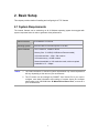
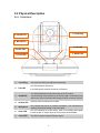
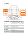
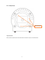
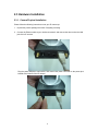
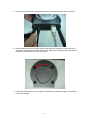
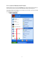
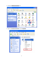
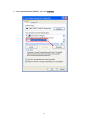
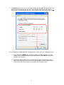
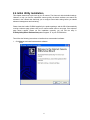
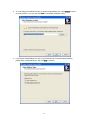
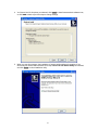
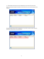
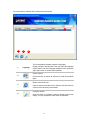
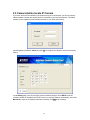
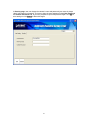
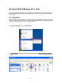
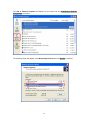
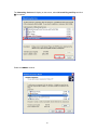
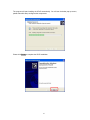
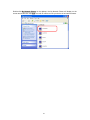
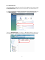
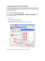
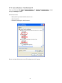
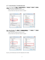
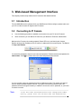
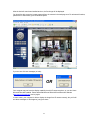
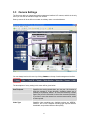
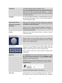
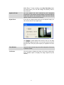
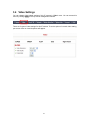

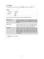
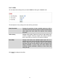
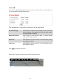
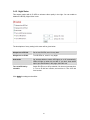
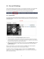
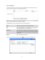
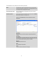
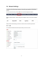
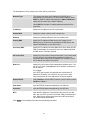
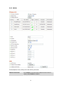
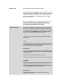
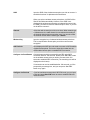
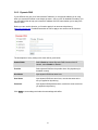
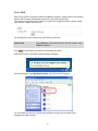
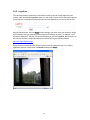
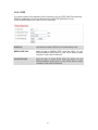
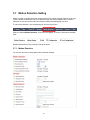
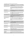
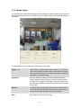
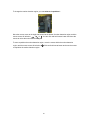


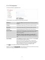
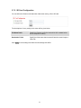
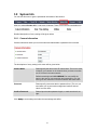
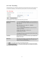
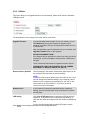
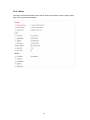
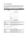
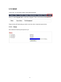
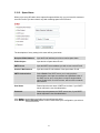
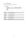
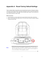
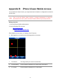
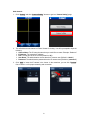
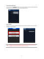
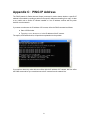
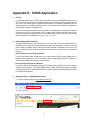
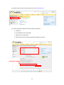
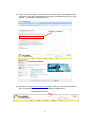
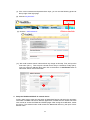
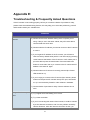
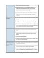
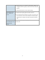
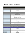
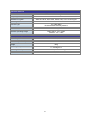

![Internet Camera - [ [ [ ANSEL ] ] ]](http://vs1.manualzilla.com/store/data/005837536_1-ce302c6b28431aa03d9b92e65549b72a-150x150.png)