1
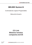
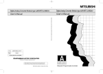
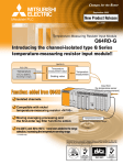
May 2003
Mitsubishi Programmable Logic Controller
New Product Release
No. 205E
CC-Link Ver. 2 Compatible Master/Local Module
QJ61BT11N
CC-Link Ver. 2 Compatible Analog Module
AJ65VBTCU-68ADVN
AJ65VBTCU-68ADIN
AJ65VBTCU-68DAVN
High-performance Model QCPU
Q02CPU
Q02HCPU
Q06HCPU
Q12HCPU
Q25HCPU
Providing more functions and better performance.
Up to 8 times more controllable points compared to previous CC-Link.
Switching between 8-point and 16-point mode for
the remote I/O station frees up unused I/O points.
Approx. eight times as many control points.
CC-Link Ver. 2 Compatible Analog Module
Compatible with existing CC-Link ver.1 network systems.
Analog module only occupies 1 station on the network, therefore the number of channels
can be increased on the CC-Link ver.2 network. (only applicable to CC-Link ver.2 networks)
High-performance Model QCPU
This model has more functions and instructions.
■ This model is compatible with CC-Link Ver. 2.
■ Imperfect derivative instruction is added to the PID control instructions.
■ Online change for SFC program file is available.
Mitsubishi Electric Corporation Nagoya Works is a factory certified for ISO14001
(standards for environmental management systems) and ISO9001(standards for
quality assurance management systems)
The amount of controllable data is increased, and wasted reserved points are eliminated. CC-Link Ver. 2
Features
■ Master module for Q Series
■ Analog Module
QJ61BT11N
AJ65VBTCU-68ADVN / AJ65VBTCU-68ADIN
AJ65VBTCU-68DAVN
GX Developer
■ GX Developer
Version 8.03D and higher product
The
logo is on the
compatible products.
(1) The control data increase by 8-times, while maintaining compatibility with the conventional product.
• Ver. 2. mode
By double, quadruple or octuple expanded cyclic setting, up to RX, RY (81092 points each), and RWw, RWr (2048 words each) is available.
• Additional mode
The Ver. 2 compatible remote station can join an existing system with minimum modification of sequence program.
• Ver. 1. mode
This mode is fully compatible with conventional products and allows reusing the existing with no revision.
Combination of QJ61BT11N compatible CPU and GX Developer
Compatible CPU
Ver. 2. mode
Ver. 1 mode
Additional mode
Compatible GX Developer
• High-performance Model QCPU (Including pre-upgraded CPU)
• Basic model QCPU
• Process CPU
• High-performance Model QCPU (Only upgraded product)
• Version 8.03D and above
No limits
• Version 8.03D and above
(2) The analog module occupies only one station, thereby greatly increasing the number of modules that can connect to one
system.
Station No. 1
Station No. 2
Station No. 21
Station No. 42
Ver. 2
(one station occupied)
First module
2nd module
21st module
Channels can be expanded up to 336 channels by connecting 42 analog modules.
Station No. 1
Station No. 4
42nd module
Station No. 61
Ver. 1
(one station occupied)
First module
2nd module
21st module
Channels can be expanded up to 168 channels by connecting 21 analog modules.
Maximum number of connected units
Number of connected analog modules
Ver. 2
42 modules
33 modules or less
Ver. 1
Number of connected remote I/O stations
2 stations
One analog module can be replaced with three stations.
Total of 64 stations including analog modules
1 station
One analog module can be replaced with three stations.
21 modules
* The maximum number of connected modules will differ according to the number of connected intelligent
device stations (including local stations) and remote device stations.
1
(3) The number of points occupied by one station can be selected to free-up unused I/O points.
• The remote I/O station 8-point or 16-point settings. (Ver. 2 mode)
The number of occupied remote I/O station points can be selected from 8 points or 16 points from the GX Developer parameters.
The devices can be used efficiently by freeing up unused I/O points.
• Use the conventional remote I/O module.
Conventional remote I/O modules (CC-Link ver.1 type) are compatible with CC-Link ver.2.
Example: Using three 8-point output modules and one 32-point output module
Master station
Station No. 2 Station No. 1
Reserved Station No. 3
Station No. 4
64 link points
Ver. 2
8-point setting
Remote I/O station Remote I/O station Remote I/O station
(Station No. 1:
(Station No. 2:
(Station No. 3:
one station occupied) one station occupied) one station occupied)
Ver. 1
Reserved Station No. 1
Reserved
Reserved Station No. 2
Reserved
Reserved Station No. 3
8-point output module
Reserved
128 link points
8-point output module
8-point output module
Remote I/O station
(Station No. 4:
one station occupied)
32-point output module
Station No. 4
CC-Link Ver.2 compatible Analog modules
Features
● Analog to Digital Converter module
AJ65VBTCU-68ADVN / AJ65VBTCU-68ADIN
● Digital to Analog Converter module
AJ65VBTCU-68DAVN
(1) The functions and specifications are compatible with Ver. 2.
Conventionally, three stations were occupied to use eight channels. With the CC-Link Ver. 2 mode, eight
channels can be used with one station. This makes it possible to connect up to 42 modules per master,
therefore dramatically increasing the number of channels in each system.
(2) Complete compatibility with conventional product
Just by setting the rotary switch, these modules work as CC-Link ver.1 compatible ones.
The parameter setting or sequence program does not need to be changed.
2
Performance specifications
(1) Analog to Digital Converter module
Item
AJ65VBTCU-68ADVN
AJ65VBTCU-68ADIN
Protection degree
IP1XB
Voltage
Analog input
Current
-10 to +10VDC (input resistance 1MΩ)
–––––
–––––
0 to 20mADC (input resistance 250Ω)
16-bit signed binary (-96 to +4095)
16-bit signed binary (-4096 to +4095)
Digital output
Accuracy
Analog input range
Digital output
Ambient
temperature
0 to 55oC
Ambient
temperature
28 ± 55oC
Max. resolution
-10 to +10V
User range setting 1
(-10 to +10V)
I/O characteristics, maximum resolution,
accuracy (accuracy relative to maximum
AJ65VBTCU-68ADVN (Voltage)
value of digital output value)
-4000 to +4000
2.5mV
1.25mV
0 to 5V
1 to 5V
0 to +4000
User range setting 2
(0 to 5V)
±0.3%
±0.2%
(±12 digit*)
(±8 digit*)
5µA
0 to 20mA
AJ65VBTCU-68ADIN (Current)
1.0mV
4 to 20mA
4µA
0 to +4000
User range setting
(0 to 20mA)
5µA
*:digit indicates digital value.
Maximum conversion speed
Absolute maximum input
1ms/1 channel
±15V
±30mA
Analog input points
8 channels/1 module
CC-Link station type
Remote device station
Number of occupied stations
Ver. 2 mode 1 station (expanded word (RWr/RWw) 16 words each RX/RY 32 points
Ver. 1 mode 3 stations (RWr/RWw) 12 words each RX/RY 32 points
Communication cable
Ver. 1.10 compatible CC-Link dedicated cable: FANC-110SBH, CS-110, FA-CBL200PSBH
Dielectric withstand voltage
Between power supply/communication system batch and analog input batch: 500VAC, 1 minute
Insulation method
Across communication system terminals and all analog input terminals: Photocoupler isolated
Across power supply system terminals and all analog input terminals: Photocoupler isolated
Across channels: Non-isolated
Noise durability
External connections
By noise simulator of 500Vp-p noise voltage, 1µs noise width and 25 to 60Hz noise frequency
One-touch connector for communication [Transmission circuit] (5pins pressure welding type, the plug for the connector is sold separately.)
One-touch connector for power supply and FG [Unit power supply and FG] (5 pins pressure welding type, the plug for the connector are
sold separately.)
One-touch connector for analog I/O (4pins pressure welding type, the plug for the connector is sold separately.)
<Sold separately>
Online connector for communication: A6CON-LJ5P
Online connector for power supply: A6CON-PWJ5P
One-touch connector
for communication
Applicable
wire size
One-touch connector
for power supply/FG
One-touch connector
for analog I/O
Communication line: Ver. 1.10 compatible CC-Link dedicated cable 0.5mm2 (AWG20) [ø2.2 to 3.0]
shielded wire 0.5 mm2 (AWG20)
0.66 to 0.98mm2 (AWG18) [ø2.2 to 3.0] Wire diameter 0.08 mm2 or more
ø1.0 to 1.4 (A6CON-P214), ø1.4 to 2.0 (A6CON-P220) [Applicable cable: 0.14 to 0.2 mm2]
ø1.0 to 1.4 (A6CON-P514), ø1.4 to 2.0 (A6CON-P520) [Applicable cable: 0.3 to 0.5 mm2]
TH35-7.5Fe, TH35-7.5A1 (conforming to JIS C 2812)
Applicable DIN rail
CC-Link connector type metal installation fitting: A6PLT-J65V1
24VDC (20.4VDC to 26.4VDC, ripple factor within 5%)
External power supply
Inrush current: 4.2A, within 1.2ms or less
Current consumption 0.10A
0.17kg
Weight
External dimensions (mm)
115 x 41 x 67
3
(1) Digital to Analog Converter module
Item
AJ65VBTCU-68DAVN
Protection degree
IP1XB
Digital output
16-bit signed binary (-4096 to +4095)
Analog output
-10 to +10VDC (input resistance 2kΩ to 1MΩ)
Accuracy
Digital output
Analog input range
I/O characteristics, maximum resolution,
accuracy (accuracy relative to maximum
-4000 to +4000
value of digital output value)
Ambient
temperature
0 to 55oC
Ambient
temperature
28 ± 55oC
-10 to +10V
±0.3%
±0.2%
User range setting 1
(-10 to +10V)
(±30 mV)
(±20mV)
±0.3%
±0.2%
(±15 mV)
(±10 mV)
Voltage
Max. resolution
0 to 5V
1.25mV
1 to 5V
0 to +4000
2.5mV
User range setting 2
(0 to 5V)
1.0mV
1.25mV
1ms/1 channel
Maximum conversion speed
Provided
Output shortcircuit protection
±12V
Absolute maximum input
Analog input points
8 channels/1 module
CC-Link station type
Remote device station
Number of occupied stations
Ver. 2 mode 1 station (expanded word (RWr/RWw) 16 words each RX/RY 32 points)
Ver. 1 mode 3 stations (RWr/RWw) 12 words each RX/RY 32 points
Communication cable
Ver. 1.10 compatible CC-Link dedicated cable: FANC-110SBH, CS-110, FA-CBL200PSBH
Dielectric withstand voltage
Between power supply/communication system batch and analog input batch: 500VAC, 1 minute
Insulation method
Across communication system terminals and all analog input terminals: Photocoupler isolated
Across power supply system terminals and all analog input terminals: Photocoupler isolated
Across channels: Non-isolated
Noise durability
External connections
By noise simulator of 500Vp-p noise voltage, 1µs noise width and 25 to 60Hz noise frequency
One-touch connector for communication [Transmission circuit] (5 pins pressure welding type, the plug for the connector is sold separately.)
One-touch connector for power supply and FG [Unit power supply and FG] (5 pins pressure welding type, the plug for the connector are
sold separately.)
One-touch connector for analog I/O (4pins pressure welding type, the plug for the connector is sold separately.)
<Sold separately>
Online connector for communication: A6CON-LJ5P
Online connector for power supply: A6CON-PWJ5P
One-touch connector
for communication
Applicable
wire size
One-touch connector
for power supply/FG
One-touch connector
for analog I/O
Communication line: Ver. 1.10 compatible CC-Link dedicated cable 0.5mm2 (AWG20) [ø2.2 to 3.0]
shielded wire 0.5 mm2 (AWG20)
0.66 to 0.98mm2 (AWG18) [ø2.2 to 3.0] Wire diameter 0.08 mm2 or more
ø1.0 to 1.4 (A6CON-P214), ø1.4 to 2.0 (A6CON-P220) [Applicable cable: 0.14 to 0.2 mm2]
ø1.0 to 1.4 (A6CON-P514), ø1.4 to 2.0 (A6CON-P520) [Applicable cable: 0.3 to 0.5 mm2]
TH35-7.5Fe, TH35-7.5A1 (conforming to JIS C 2812)
Applicable DIN rail
CC-Link connector type metal installation fitting: A6PLT-J65V1
24VDC (20.4VDC to 26.4VDC, ripple factor within 5%)
External power supply
Inrush current: 4.2A, within 1.2ms
Current consumption 0.15A
0.16kg
Weight
External dimensions (mm)
115 x 41 x 67
4
Differences between CC-Link Ver. 2 and Ver. 1
CC-Link Ver. 2 specification
Specification
Item
Maximum number of link points
Expanded cyclic setting
Number of
link points
per station
Remote input/output (RX, RY): 8192 points each, Remote register (RWw): 2048 points each,
Remote register (RWr): 2048 points each
Single
Double
Octuple
Quadruple
Number of link points per number of occupied station
Remote input/output (RX, RY)
Remote register (RWw)
Remote register (RWr)
32 points each
4 words
4 words
32 points each
8 words
8 words
64 points each
16 words
16 words
128 points each
32 words
32 words
Remote input/output (RX, RY)
Remote register (RWw)
Remote register (RWr)
32 points each
4 words
4 words
32 points each
8 words
8 words
64 points each
16 words
16 words
128 points each
32 words
32 words
2 station
occupied
Remote input/output (RX, RY)
Remote register (RWw)
Remote register (RWr)
64 points each
8 words
8 words
96 points each
16 words
16 words
192 points each
32 words
32 words
384 points each
64 words
64 words
3 station
occupied
Remote input/output (RX, RY)
Remote register (RWw)
Remote register (RWr)
96 points each
12 words
12 words
160 points each
24 words
24 words
320 points each
48 words
48 words
640 points each
96 words
96 words
4 station
occupied
Remote input/output (RX, RY)
Remote register (RWw)
Remote register (RWr)
128 points each
16 words
16 words
224 points each
32 words
32 words
448 points each
64 words
64 words
896 points each
128 words
128 words
1 station
occupied
Specification
Item
Maximum number of link points
Remote input/output (RX, RY): 2048 points each Remote register (RWw): 256 words
Remote register (RWr): 256 words
Number of link points per station
Remote input/output (RX, RY): 32 points each Remote register (RWw): 4 words
Remote register (RWr): 4 words
1 station
occupied
Remote input/output (RX, RY): 32 points each Remote register (RWw): 4 words
Remote register (RWr): 4 words
2 stations
occupied
Remote input/output (RX, RY): 64 points each Remote register (RWw): 8 words
Remote register (RWr): 8 words
3 stations
occupied
Remote input/output (RX, RY): 96 points each Remote register (RWw): 12 words
Remote register (RWr): 12 words
4 stations
occupied
Remote input/output (RX, RY): 128 points each Remote register (RWw): 16 words
Remote register (RWr): 16 words
Number of link points
per number of
occupied station
5
Ever-advancing high-performance model QCPU
Features
(1) The CC-Link Ver. 2 additional mode is supported.
The additional mode with increased functions is supported with the CC-Link Ver. 2 compatible master/local module
QJ61BT11N.
(2) Imperfect derivative PID control instructions have been added.
The conventional PID control instruction (PIDCONT instruction) was capable only of perfect derivative operations, but now
imperfect derivative operations are available with the newly added S.PIDCONT instructions. The target level can be reached
more smoothly using the PID operations which are not easily affected by higher harmonic noise.
(3) Online change for SFC program files is available.
Until now, only Online change for ladder programs was available. With this high-performance model, the online change for
SFC program files can now be done.
SFC program file
CPU
0
1
2
Write during
RUN
(4) High speed processing of floating point comparison instructions.
The time for processing the floating point comparison instructions has been increased by six-times from the conventional
40µs for one instruction to 6.4µs for one instruction. The time required to scan a program containing many floating point
comparison instructions can be shortened.
E>
E12, 34
DO
Instruction processing time 40µS ➞ 6.4µS
List of additional functions
Details of upgraded high-performance module QCPU
Additional function
Serial No. (* 1)
• SFC program batch write during RUN
04122 or higher
• Change of file memory capacity
• CC-Link Ver. 2 additional mode compatible (* 3)
• Imperfect derivative PID operation function
• Faster floating point comparison instruction.
05032 or higher
*1. Serial No. for the compatible high-performance model QCPU.
*2. GX Developer version with which additional functions can be set and programmed.
*3. Combinations with CC-Link Ver. 2 compatible master module QJ61BT11N are possible.
6
Compatible GX Developer (* 2)
Version 8 or above
Version 8.03D or above
Manuals
Manual name
High Performance model QCPU (Q mode) User's Manual
(Hardware Design, maintenance and Inspection)
QCPU (Q mode) User's Manual (Hardware)
QCPU (Q mode) / QnACPU Programming Manual (Common Instructions)
QCPU (Q mode) / QnACPU Programming Manual (SFC)
QCPU (Q mode) / QnACPU Programming Manual (PID Control Instructions)
CC-Link System Master/Local Module Users Manual (Hardware) QJ61BT11N
CC-Link System Master/Local Module Users Manual QJ61BT11N
Analog - Digital Converter Module type AJ65VBTCU-68ADVN/ADIN User's Manual
Digital - Analog Converter Module type AJ65VBTCU-68DAVN User's Manual
GX Developer Version 8 Operating Manual
GX Developer Version 8 Operating Manual (SFC)
Manual shipping style
B/SH No.
Type code
Sold separately
SH-080037-G
13JL97
Enclosed with Q3 B base
Sold separately
Sold separately
Sold separately
Enclosed with the product
Sold separately
Sold separately
Sold separately
Sold separately
Sold separately
IB-0800061-L
SH-080039-G
SH-080041-D
SH-080040-E
IB-0800250-A
SH-080394E-A
SH-080401E-A
SH-0800402E-A
SH-080373E-A
SH-080374E-A
13JL96
13JF58
13JF60
13JF59
13JP16
13JR64
13JR65
13JR66
13JU41
13JU42
Microsoft Windows and Microsoft Windows NT are registered trademarks of Microsoft Corporation in the United States and other countries.
Netscape is a registered trademark of Netscape Communications Corporation in the United States and other countries.
Ethernet is a registered trademark of Xerox Corporation.
Other company names and product names used in this document are trademarks or registered trademarks of the respective companies.
Country/Region
Sales office
Tel/Fax
U.S.A
Mitsubishi Electric Automation Inc.
500 Corporate Woods Parkway Vernon Hills, IL 60061
Tel : +1-847-478-2100
Fax : +1-847-478-2396
Brazil
MELCO-TEC Rep. Com.e Assessoria Tecnica Ltda.
AV. Paulista 1471, Conj. 308, Sao Paulo City, Sao Paulo State, Brazil
Tel : +55-11-283-2423
Fax : +55-11-288-3047
Germany
Mitsubishi Electric Europe B.V. German Branch
Gothaer Strsse 8 D-40880 Ratingen, GERMANY
Tel : +49-2102-486-0
Fax : +49-2102-486-7170
U.K
Mitsubishi Electric Europe B.V. UK Branch
Travellers Lane, Hatfield, Herts., AL10 8XB,UK
Tel : +44-1707-276100
Fax : +44-1707-278695
Italy
Mitsubishi Electric Europe B.V. Italian Branch
Centro Dir. Colleoni, Pal. Perseo - Ingr.2
Via Paracelso 12, 20041 Agrate B., Milano, Italy
Tel : +39-039-6053344
Fax : +39-039-6053312
Spain
Mitsubishi Electric Europe B.V. Spanish Branch
Carretera de Rubi 76-80
08190 - Sant Cugat del Valles, Barcelona, Spain
France
Mitsubishi Electric Europe B.V. French Branch
25 Boulevard des Bouvets, F-92741 Nanterre Cedex, France
South Africa
Circuit Breaker Industries LTD.
Tripswitch Drive, Elandsfontein Gauteng, South Africa
Hong Kong
Ryoden Automation Ltd.
10th Floor, Manulife Tower, 169 Electric Road, North Point, HongKong
China
Ryoden Automation Shanghai Ltd.
3F Block5 Building Automation Instrumentation Plaza 103 Cao Bao Rd. Shanghai 200233 China
Setsuyo Enterprise Co., Ltd.
6F., No.105 Wu-Kung 3rd.RD, Wu-Ku Hsiang, Taipei Hsine, Taiwan
Tel : +86-21-6475-3228
Fax : +86-21-6484-6996
Tel : +886-2-2299-2499
Fax : +886-2-2299-2509
Korea
HAN NEUNG TECHNO CO.,LTD.
1F Dong Seo Game Channel Bldg., 660-11,Deungchon-dong Kangsec-ku, Seoul, Korea
Tel : +82-2-3660-9552
Fax : +82-2-3664-8372
Singapore
Mitsubishi Electric Asia Pte, Ltd.
307 ALEXANDRA ROAD #05-01/02,
MITSUBISHI ELECTRIC BUILDING SINGAPORE 159943
Tel : +65-6473-2308
Fax : +65-6476-7439
Thailand
F. A. Tech Co.,Ltd.
898/28,29,30 S.V.CITY BUILDING,OFFICE TOWER 2,FLOOR
17-18 RAMA 3 ROAD,BANGKPONGPANG,YANNAWA,BANGKOK 10120
Tel : +66-2-682-6522
Fax : +66-2-682-6020
Indonesia
P.T. Autoteknindo SUMBER MAKMUR
JL. MUARA KARANG SELATAN BLOK A UTARA NO.1 KAV.
NO.11 KAWASAN INDUSTRI/ PERGUDANGAN JAKARTA - UTARA 14440
Tel : +62-21-663-0833
Fax : +62-21-663-0832
India
Messung Systems Put,Ltd.
Electronic Sadan NO:111 Unit No15, M.I.D.C BHOSARI,PUNE-411026
Tel : +91-20-712-2807
Fax : +91-20-712-0391
Australia
Mitsubishi Electric Australia Pty. Ltd.
348 Victoria Road, PostalBag, No 2, Rydalmere, N.S.W 2116, Australia
Tel : +61-2-9684-7777
Fax : +61-2-9684-7245
Taiwan
Tel : +34-93-565-3131
Fax : +34-93-589-2948
Tel : +33-1-5568-5568
Fax : +33-1-5568-5685
Tel : +27-11-928-2000
Fax : +27-11-392-2354
Tel : +852-2887-8870
Fax : +852-2887-7984
HEAD OFFICE: 1-8-12, OFFICE TOWER Z 14F HARUMI GHUO-KU 104-6212, JAPAN
NAGOYA WORKES: 1-14, YADAMINAMI5, HIGASIKU, NAGOYA, JAPAN
Specifications subject to change without notice.
Printed in Japan on recycled paper.
MDOC (0305)