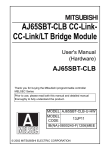
1
Analog-Digital
Converter Module
User's Manual
(Hardware)
AJ65VBTCU-68ADVN/ADIN
Thank you for buying the Mitsubishi general-purpose programmable
controller MELSEC Series
Prior to use, please read both this manual and detailed manual
thoroughly and familiarize yourself with the product.
MODEL AJ65V-68ADN-U-HW
MODEL
13JP19
CODE
IB(NA)-0800251-G(1206)MEE
© 2003 MITSUBISHI ELECTRIC CORPORATION
SAFETY PRECAUTIONS
(Read these precautions before using this product.)
Before using this product, please read this manual and the relevant manuals
carefully and pay full attention to safety to handle the product correctly.
These precautions apply only to this equipment.
Refer to the user 's manual of the CPU module to use for a description of the
programmable controller system safety precautions.
In this manual, the safety precautions are classified into two levels:
"
WARNING " and "
CAUTION".
WARNING
Indicates that incorrect handling may cause
hazardous conditions, resulting in death or severe
injury.
CAUTION
Indicates that incorrect handling may cause
hazardous conditions, resulting in minor or moderate
injury or property damage.
Under some circumstances, failure to observe the precautions given under
"
CAUTION" may lead to serious consequences.
Observe the precautions of both levels because they are important for personal
and system safety.
Make sure that the end users read this manual and then keep the manual in a safe
place for future reference.
[Design Precautions]
WARNING
● In the case of a communication failure in the network, data in the master
module are held.
Check the communication status information (SB, SW) and configure an
interlock circuit in the sequence program to ensure that the entire system will
operate safely.
A-1
[Design Precautions]
CAUTION
● Do not install the control lines or communication cables together with the main
circuit lines or power cables.
Keep a distance of 100mm (3.94 inches) or more between them.
Failure to do so may result in malfunction due to noise.
[Installation Precautions]
CAUTION
● Use the programmable controller in an environment that meets the general
specifications in the detailed manual.
Failure to do so may result in electric shock, fire, malfunction, or damage to or
deterioration of the product.
● Securely fix the module with a DIN rail or CC-Link connector type metal
installation fitting.
Not doing so can cause a drop or malfunction.
● Do not directly touch any conductive part of the module.
Doing so can cause malfunction or failure of the module.
A-2
[Wiring Precautions]
CAUTION
● Shut off the external power supply for the system in all phases before wiring.
Failure to do so may result in damage to the product.
● Ground the FG pin and FG1 pin to the protective ground conductor dedicated
to the programmable controller.
Failure to do so may result in malfunction.
● Check the rated voltage and pin layout before wiring to the module, and
connect the cables correctly.
Connecting a power supply with a different voltage rating or incorrect wiring
may cause a fire or failure.
● Do not insert the one-touch connector plug for I/O of the one-touch connector
type/connector type compact remote I/O unit into the one-touch connector for
analog I/O accidentally.
Doing so can cause the module to be damaged.
● Prevent foreign matter such as dust or wire chips from entering the module.
Such foreign matter can cause a fire, failure, or malfunction.
● Always fit a non-wired, one-touch connector plug to the open one-touch
connector for power supply and FG.
Not doing so can cause a failure or malfunction.
● Place the cables in a duct or clamp them.
If not, dangling cable may swing or inadvertently be pulled, resulting in
damage to the module or cables or malfunction due to poor contact.
● Do not install the control lines or communication cables together with the main
circuit lines or power cables.
Failure to do so may result in malfunction due to noise.
● When disconnecting the cable from the module, do not pull the cable by the
cable part.
Loosen the screws of connector before disconnecting the cable.
Failure to do so may result in damage to the module or cable or malfunction
due to poor contact.
A-3
[Wiring Precautions]
CAUTION
● Smoke and fire may occur when an overcurrent flows intermittently for a long
period of time. To avoid this, configure a safety circuit, such as an external
fuse, to protect the product.
[Starting and Maintenance Precautions]
CAUTION
● Do not touch any pin while power is on. Doing so will cause malfunction.
● Shut off the external power supply for the system in all phases before cleaning
the module.
Failure to do so may cause the module to fail or malfunction.
● Do not disassemble or modify the modules.
Doing so may cause failure, malfunction, injury, or a fire.
● Do not drop or apply strong shock to the module. Doing so may damage the
module.
● Shut off the external power supply for the system in all phases before
mounting or removing the module to or from the panel.
Failure to do so may cause the module to fail or malfunction.
● Before handling the module, touch a grounded metal object to discharge the
static electricity from the human body.
Failure to do so may cause the module to fail or malfunction.
[Disposal Precautions]
CAUTION
● When disposing of this product, treat it as industrial waste.
A-4
CONDITIONS OF USE FOR THE PRODUCT
(1) Mitsubishi programmable controller ("the PRODUCT") shall be used in
conditions;
i) where any problem, fault or failure occurring in the PRODUCT, if any,
shall not lead to any major or serious accident; and
ii) where the backup and fail-safe function are systematically or
automatically provided outside of the PRODUCT for the case of any
problem, fault or failure occurring in the PRODUCT.
(2) The PRODUCT has been designed and manufactured for the purpose of
being used in general industries.
MITSUBISHI SHALL HAVE NO RESPONSIBILITY OR LIABILITY
(INCLUDING, BUT NOT LIMITED TO ANY AND ALL RESPONSIBILITY
OR LIABILITY BASED ON CONTRACT, WARRANTY, TORT, PRODUCT
LIABILITY) FOR ANY INJURY OR DEATH TO PERSONS OR LOSS OR
DAMAGE TO PROPERTY CAUSED BY the PRODUCT THAT ARE
OPERATED OR USED IN APPLICATION NOT INTENDED OR
EXCLUDED BY INSTRUCTIONS, PRECAUTIONS, OR WARNING
CONTAINED IN MITSUBISHI'S USER, INSTRUCTION AND/OR SAFETY
MANUALS, TECHNICAL BULLETINS AND GUIDELINES FOR the
PRODUCT.
("Prohibited Application")
Prohibited Applications include, but not limited to, the use of the PRODUCT
in;
• Nuclear Power Plants and any other power plants operated by Power
companies, and/or any other cases in which the public could be
affected if any problem or fault occurs in the PRODUCT.
• Railway companies or Public service purposes, and/or any other cases
in which establishment of a special quality assurance system is
required by the Purchaser or End User.
• Aircraft or Aerospace, Medical applications, Train equipment, transport
equipment such as Elevator and Escalator, Incineration and Fuel
devices, Vehicles, Manned transportation, Equipment for Recreation
and Amusement, and Safety devices, handling of Nuclear or
Hazardous Materials or Chemicals, Mining and Drilling, and/or other
applications where there is a significant risk of injury to the public or
property.
A-5
Notwithstanding the above, restrictions Mitsubishi may in its sole discretion,
authorize use of the PRODUCT in one or more of the Prohibited
Applications, provided that the usage of the PRODUCT is limited only for
the specific applications agreed to by Mitsubishi and provided further that
no special quality assurance or fail-safe, redundant or other safety features
which exceed the general specifications of the PRODUCTs are required.
For details, please contact the Mitsubishi representative in your region.
A-6
REVISIONS
*The manual number is given on the bottom right of the cover.
Print date
*Manual number
Mar., 2003
IB(NA)-0800251-A
First edition
Revision
Jul., 2005
IB(NA)-0800251-B
Partial correction
SAFETY PRECAUTIONS
Sep., 2006
IB(NA)-0800251-C
Partial correction
Chapter 3, Chapter 8
Apr., 2007
IB(NA)-0800251-D
Partial correction
Section 2.1, Section 6.2, Chapter 8
Sep., 2010
IB(NA)-0800251-E
Addition
CONDITIONS OF USE THE PRODUCT
Partial correction
SAFETY PRECAUTIONS, About Manuals,
Compliance with the EMC and Low Voltage
Directives, Section 2.1, Chapter 3, Section 5.2,
Section 6.1, Section 6.2, Chapter 7
Deletion
Section 5.1
Dec., 2011
IB(NA)-0800251-F
Addition
SAFETY PRECAUTIONS(Chinese)
Partial correction
COMPLIANCE WITH EMC AND LOW VOLTAGE
DIRECTIVES
Jun., 2012
IB(NA)-0800251-G
Partial correction
Section 5.1, 6.2
This manual confers no industrial property rights or any rights of any other kind,
nor does it confer any patent licenses. Mitsubishi Electric Corporation cannot be
held responsible for any problems involving industrial property rights which may
occur as a result of using the contents noted in this manual.
© 2003 MITSUBISHI ELECTRIC CORPORATION
A-7
CONTENTS
1. OVERVIEW .................................................................................................... 1
2. SPECIFICATION ............................................................................................ 2
2.1
Performance specifications ................................................................... 2
3. NAMES AND SETTING OF PARTS............................................................... 4
4. LOADING AND INSTALLATION .................................................................... 8
4.1
Precautions when handling ................................................................... 8
4.2
Installation environment ........................................................................ 8
5. DATA LINK CABLE WIRING.......................................................................... 9
5.1
Connection of the CC-Link dedicated cables ........................................ 9
6. WIRING ........................................................................................................ 11
6.1
Wiring precautions .............................................................................. 11
6.2
Wiring of module with external equipment .......................................... 12
7. HOW TO WIRE THE ONE-TOUCH CONNECTOR PLUG .......................... 14
8. EXTERNAL DIMENSION DIAGRAM ........................................................... 16
A-8
MANUAL
The following manuals are also related to this product.
In necessary, order them by quoting the details in the tables below.
Detailed Manual
Manual number
(Model code)
Manual name
Analog-Digital Converter Module type AJ65VBTCU-68ADVN/ADIN
User's Manual
SH-080401E
(13JR65)
Related Manual
Manual name
Manual number
(Model code)
CC-Link System Master/Local Module Type AJ61BT11/A1SJ61BT11
User's Manual
IB-66721
(13J872)
CC-Link System Master/Local Module Type
AJ61QBT11/A1SJ61QBT11 User's Manual
IB-66722
(13J873)
MELSEC-Q CC-Link System Master/Local Module User's Manual
SH-080394E
(13JR64)
MELSEC-L CC-Link System Master/Local Module User's Manual
SH-080895ENG
(13JZ41)
COMPLIANCE WITH EMC AND LOW VOLTAGE DIRECTIVES
(1)
Method of ensuring compliance
To ensure that Mitsubishi programmable controllers maintain EMC
and Low Voltage Directives when incorporated into other
machinery or equipment, certain measures may be necessary.
Please refer to one of the following manuals.
• User's manual for the CPU module or head module used
• Safety Guidelines
(This manual is included with the CPU module, base unit, or
head module)
The CE mark on the side of the programmable controller indicates
compliance with EMC and Low Voltage Directives.
(2)
Additional measures
To ensure that this product maintains EMC and Low Voltage
Directives, please refer to one of the manuals listed under (1).
A-9
1. OVERVIEW
This user's manual explains the specifications, names and setting of
parts, wiring and others of Type AJ65VBTCU-68ADVN analog-digital
converter module (hereafter abbreviated to the "AJ65VBTCU68ADVN") and Type AJ65VBTCU-68ADIN analog-digital converter
module (hereafter abbreviated to the "AJ65VBTCU-68ADIN") which is
used as a remote device station of a CC-Link system.
In this manual, the AJ65VBTCU-68ADVN and AJ65VBTCU-68ADIN are
generically referred to as the AJ65VBTCU-68ADVN/ADIN.
Confirm if the following items are included in the package after
unpacking.
Item name
Number of items
Analog-Digital Converter Module type AJ65VBTCU-68ADVN
1
Analog-Digital Converter Module type AJ65VBTCU-68ADIN
1
1
2. SPECIFICATION
2.1
Performance specifications
The performance specifications of the AJ65VBTCU-68ADVN/ADIN are
shown below. For general specifications, refer to detailed manual.
Item
AJ65VBTCU-68ADVN
AJ65VBTCU-68ADIN
Protection class
Analog
input
Voltage
IP1XB
-10 to 0 to 10V DC
(input resistance 1MΩ)
-
-
0 to +20mA DC
(input resistance 250Ω)
Current
Digital output
16-bit signed binary (-4096 to 4095)
16-bit signed binary (-96 to 4095)
Accuracy
Analog
input range
-10 to 10V
I/O characteristics, maximum
resolution, accuracy
(accuracy relative to
maximum value of digital
output value)
AJ65VBTCU68ADVN
(Voltage)
User range
setting 1
(-10 to 10V)
Digital
Max.
Ambient
Ambient
output temperature temperature Resolution
0 to 55°C
25±5°C
-4000
to
4000
2.5mV
1.25mV
0 to 5V
1 to 5V
User range
setting 2
(0 to 5V)
0 to
4000
±0.3%
(±12 digit*1)
±0.2%
(±8 digit*1)
1.0mV
0 to 20mA
AJ65VBTCU68ADIN
(Current)
4 to 20mA
User range
setting
(0 to 20mA)
Maximum conversion speed
Absolute maximum input
5µA
0 to
4000
4µA
1ms/channel.
Current ±30mA*2
Voltage ±15 V
Analog input points
8 channels/module
CC-Link station type
Remote device station
(Ver.1 remote device station, Ver.2 remote device station)
Number of occupied stations
Communication cable
Ver.1 remote device station (Ver.1 compatible slave station) setting:
3 stations (32 points for RX and RY, 12 points for RWr and RWw)
Ver.2 remote device station (Ver.2 compatible slave station) setting:
1 station (32 points for RX and RY, 16 points for RWr and RWw,
expanded cyclic settings: 4 times)
Ver.1.10 compatible CC-Link dedicated cable:
FANC-110SBH, FA-CBL200PSBH, CS-110
2
Item
AJ65VBTCU-68ADVN
Insulation
AJ65VBTCU-68ADIN
Insulated area
Insulation
method
Across communication
system terminals and all
analog input terminals
Photocoupler
Across power supply
system terminals and all
analog input terminals
Transformer
Between channels
Non-insulation
Dielectric
withstand voltage
Insulation
resistance
500VAC for 1
minute
5MΩ or higher,
measured with
500VDC
insulation
resistance tester
-
-
Noise durability
By noise simulator of 500Vp-p noise voltage, 1µs noise width and 25 to 60Hz noise
frequency
External wiring system
One-touch connector for communication [Transmission circuit]
(5 pins pressure welding type, the plug for the connector is sold separately)
One-touch connector for power supply and FG [Unit power supply and FG]
(5 pins pressure welding type, the plug for the connector is sold separately)
One-touch connector for analog I/O
(4 pins pressure welding type, the plug for the connector is sold separately)
<Sold separately>
Online connector for communication: A6CON-LJ5P
Online connector for power supply: A6CON-PWJ5P
Applicable
wire size
One-touch
connector for
communication
Communication line : Ver. 1.10 compatible CC-Link dedicated cable
0.5mm2 (20AWG) [φ2.2 to 3.0], shielded wire 0.5mm2 (20AWG)
One-touch
connector for
power supply
and FG
0.66 to 0.98 mm2 (18AWG) [φ2.2 to 3.0]
Wire diameter 0.16 mm2 or more
One-touch
connector for
analog I/O
φ1.0 to 1.4 (A6CON-P214), φ1.4 to 2.0 (A6CON-P220)
[Applicable cable: 0.14 to 0.2 mm2]
φ1.0 to 1.4 (A6CON-P514), φ1.4 to 2.0 (A6CON-P520)
[Applicable cable: 0.3 to 0.5 mm2]
TH35-7.5Fe, TH35-7.5Al (conforming to JIS C 2812)
Applicable DIN rail
CC-Link connector type metal installation fitting: A6PLT-J65V1
24VDC (20.4 to 26.4VDC, ripple factor within 5%)
External power supply
Inrush current: 4.2A, within 1.2ms
Current consumption: 0.10A (When 24VDC)
Weight
0.17kg
*1: digit indicates digital value.
*2: Current value indicates value of instant input current that does not break module inner
electrical resistance.
Point
A/D conversion needs to be powered on 30 minutes prior to operation for
compliance to the specification (sccuracy).
3
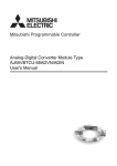
3. NAMES AND SETTING OF PARTS
The name of each part in the AJ65VBTCU-68ADVN/ADIN is shown.
[Pin layout and signals name]
Pin arrangement
Pin No.
Signal name
1
CONA,B
7)
3)
54321
CONA
CON1 to 8
CONB
1)
4321
2)
4
NC
5
SLD
1
CH V+/I+*1
2
CH V-/I-*1
3
NC
4
SLD
1
FG
2
+24V (UNIT)
3
24G (UNIT)
CONC,D
CON4
4
AG
CON5
5
FG1
*1: indicates the connector
number. (For CON1, the
value in is 1.)
CON7
CON8
5), 6)
54321
CONC
COND
A module view
from the top
8)
DG
CON2
CON6
4)
DB
3
CON1
CON3
9)
DA
2
10)
4
No.
Name and
appearance
Description
POWER
ON : Power supply on
OFF : Power supply off
Normal
mode
RUN
On : Normal operation
Flickering:
0.1s intervals:
Input range setting error, mode select switch setting error.
This module is used as the Ver.2 remote device station
(Ver.2 compatible slave station) when the network
parameter mode is set to remote network Ver.1 mode.
0.5s intervals:
Average value setting (count, time) error. Mode select
switch setting is changed after power-on.
Off : 24VDC power supply shutoff or watchdog timer error
occurred.
On
1)
Operation
status display
LED
: Indicates that the SELECT/SET switch is in the SET
position.
Flickering:
0.1s intervals:
Mode select switch setting error
0.5s intervals:
An attempt was made to make setting outside the setting
range at the time of offset/gain setting.
Off : Indicates that the SELECT/SET switch is in the SELECT or
center position.
Test
mode
L RUN
On
Off
: Normal communication
: Communication cutoff (time expiration error)
On
L ERR.
:Indicates that transmission speed setting or station number setting is
outside the range.
Flicker at fixed intervals:
Indicates that transmission speed setting or station number setting was
changed from that at power-on.
Flicker at unfixed intervals:
Indicates that you forgot fitting the terminating resistor or the module or
CC-Link dedicated cable is affected by noise.
Off : Indicates normal communications.
Normal
mode
Normally OFF
Test
mode
TEST:ON
The OFFSET/GAIN/ CH LEDs lit change every time the
SELECT/SET switch is moved to SELECT.
2)
Offset/gain
adjusting LEDs
TEST
CH
OFFSET
GAIN
3)
SELECT/SET
switch
Used to make offset/gain setting in the test mode.
5
No.
Name and
appearance
Description
The switch to be used for selecting the mode among Ver. remote device station (Ver.
-compatible slave station)/Normal mode/Test mode
AJ65VBTCU-68ADVN
4)
Mode select
switch
(Factory-set to
"0")
0: Normal mode
1: Test mode
(User range setting 1)
2: Test mode
(User range setting 2)
Ver.1 remote
device station
(Ver.1compatible
slave station)
0: Normal mode
1: Test mode
(User range
setting)
Ver.2 remote
device station
(Ver.2compatible
slave station)
3: Normal mode
4: Test mode
(User range setting 1)
5: Test mode
(User range setting 2)
Ver.2 remote
device station
(Ver.2compatible
slave station)
3: Normal mode
4: Test mode
(User range
setting)
-
ON
5)
B RATE
1 2 4
Transmission
speed setting
switches
AJ65VBTCU-68ADIN
Ver.1 remote
device station
(Ver.1compatible
slave station)
6 to 7: Use prohibited
Set value
-
Setting switches
2, 5 to 7: Use
prohibited
Transmission speed
4
2
1
0
OFF
OFF
OFF
156kbps
1
OFF
OFF
ON
625kbps
2
OFF
ON
OFF
2.5Mbps
3
OFF
ON
ON
5.0Mbps
4
ON
OFF
OFF
10Mbps
Always set the transmission speed within the above range.
The switches are all factory-set to OFF.
Making any other setting than the above will result in an error flickering the "L ERR." LED.
Confirm the transmission speed setting switch numbers on the seal located on the side
face of the connector for analog I/O.
6
No.
Name and
appearance
Description
Use the switches in STATION NO. "10", "20" and "40" to set the tens of the station number.
Use the switches in STATION NO. "1", "2", "4" and "8" to set the units of the station
number.
The switches are all factory-set to OFF.
Always set the station number within the range 1 to 64.
Setting any other number than 1 to 64 will result in an error, flickering the "L ERR." LED.
You cannot set the same station number to two or more stations.
ON
6)
STATION NO.
1 2 4 8 10 20 40
Station number
setting switches
Tens
Units
Station
number
40
20
10
8
4
2
1
1
OFF
OFF
OFF
OFF
OFF
OFF
ON
2
OFF
OFF
OFF
OFF
OFF
ON
OFF
3
OFF
OFF
OFF
OFF
OFF
ON
ON
4
OFF
OFF
OFF
OFF
ON
OFF
OFF
:
:
:
:
:
:
:
:
10
OFF
OFF
ON
OFF
OFF
OFF
OFF
11
OFF
OFF
ON
OFF
OFF
OFF
ON
:
:
:
:
:
:
:
:
64
ON
ON
OFF
OFF
ON
OFF
OFF
(Example) To set the station number to "32", set the switches as indicated below.
Tens
Units
Station
number
40
20
10
8
4
2
1
32
OFF
ON
ON
OFF
OFF
ON
OFF
Confirm the station number setting switch numbers on the seal located on the side face of
the connector for analog I/O.
7)
One-touch
connector for
communication
A one-touch connector for connection of the communication line
When carrying out wiring, connect two optional one-touch connector plugs for
communication at top and bottom.
8)
One-touch
connector for
power supply
and FG
A one-touch connector for connection of the module power supply line and FG.
When carrying out jumper wiring, connect two optional one-touch connector plugs for
power supply and FG at top and bottom.
9)
One-touch
connector for
analog I/O
One-touch connector for analog I/O
Connect a one-touch connector plug when wiring.
10) DIN rail hook
Used to mount the module to the DIN rail.
Point
After power-on, do not change the mode select switch setting.
If you change it midway during operation, the setting at power-on is valid.
7
4. LOADING AND INSTALLATION
4.1
Precautions when handling
The following is an explanation of handling precautions of the module.
(1)
4.2
Because the case of the module is made of resin, be careful not to
drop it or expose it to strong impact.
Installation environment
Never install the module in the following environments:
(1)
Locations where the ambient temperature is outside the range of 0
to 55°C.
(2)
Locations where the ambient humidity is outside the range of 10 to
99%RH.
(3)
Locations where dew condensation takes place due to sudden
temperature changes.
(4)
Locations where there are corrosive and/or combustible gasses.
(5)
Locations where there is a high level of conductive power (such as
dust and iron filings, oil mist, salt, and organic solvents).
(6)
Locations exposed to the direct rays of the sun.
(7)
Locations where strong power and magnetic fields are generated.
(8)
Locations where vibration and shock are directly transmitted to the
main module.
8
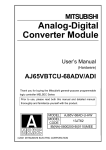
5. DATA LINK CABLE WIRING
5.1
Connection of the CC-Link dedicated cables
Connect the CC-Link dedicated cable between the AJ65VBTCU68ADVN/ADIN and master module as shown below.
One-touch connector plug
for communication
Online connector for
(A6CON-L5P)
communication
(A6CON-LJ5P)
One-touch connector plug
with terminating resistor
(A6CON-TR11(N))
Connect a wireless
connector to an open
connector for power
supply and FG.
24VDC
One-touch connector plug for power
supply and FG (A6CON-PW5P/A6CONPW5P-SOD)
Online connector for
power supply and FG (A6CON-PWJ5P)
[Power supply and FG cable wiring diagram]
Online connector for
power supply and FG
External supply
CONC
1
power cable (IN)
1 FG
2
3
4
5
External supply
power cable (OUT)
1
2
3
4
5
* The power cables cannot be conected with the
other remote I/O module having the one-touch
connector for power supply.
9
2 +24V (UNIT)
3 24G (UNIT)
4 AG
5 FG1
COND
1 FG
2 +24V (UNIT)
3 24G (UNIT)
4 AG
5 FG1
[CC-Link dedicated cable wiring diagram]
Terminating
resistor
Master module
NC
(Blue)
NC
DA
(White)
SLD
DB
(Yellow)
FG
DG
Online connector
for communication
(Blue)
(White)
(Yellow)
SLD
(Blue)
(White)
(Yellow)
SLD
1
2
3
4
5
CONA
1 DA
2 DB
3 DG
4 NC
5 SLD
1
2
3
4
5
CONB
1 DA
2 DB
3 DG
4 NC
5 SLD
Online connector
for communication
(Blue)
(White)
(Yellow)
SLD
1
2
3
4
5
CONA
1 DA
2 DB
3 DG
4 NC
5 SLD
1
2
3
4
5
CONB
1 DA
2 DB
3 DG
4 NC
5 SLD
Terminating
resistor
(A6CON-TR11(N))
FG
Ver.1.10 Compatible CC-Link dedicated cable (FANC-110SBH,CS-110,FA-CBL200PSBH)
Point
• On this unit, use the Ver. 1.10-compatible CC-Link dedicated cable
(FANC-110SBH, CS-110, FA-CBL200PSBH).
You cannot use the Ver. 1.10-compatible CC-Link dedicated cables of
other than the above types, CC-Link dedicated cables and CC-Link
dedicated, high-performance cables.
• The shield cable of the CC-Link dedicated cable should be connected
to "SLD" in each module, and both ends should be grounded through
"FG".
10
6. WIRING
6.1
Wiring precautions
To obtain maximum performance from the functions of AJ65VBTCU68ADVN/ADIN and improve the system reliability, an external wiring
with high durability against noise is required.
The precautions when performing external wiring are as follows:
(1)
Use separate cables for the AC and AJ65VBTCU-68ADVN/ADIN
external input signals, in order not to be affected by the AC side
surge or conductivity.
(2)
Do not bundle or place with load carrying wires other than the main
circuit line, high voltage line or programmable controller. Noises,
surges, or conductivity may affect the system.
(3)
Place a one-point grounding on the programmable controller side
for the shielded line or shielded cable. However, depending on the
external noise conditions, it may be better have a grounding
externally.
(4)
Smoke and fire may occur when an overcurrent flows intermittently
for a long period of time. To avoid this, configure a safety circuit,
such as an external fuse, to protect the product.
11
6.2
Wiring of module with external equipment
(1)
AJ65VBTCU-68ADVN (For voltage input)
Signal souce 0 to
10V
*1 Shield
CON1 CH.1
1 CH.1 V+
2 CH.1 V3
NC
SLD
4
500k
500k
CON8 CH.8
1 CH.8 V+
2 CH.8 VNC
3
SLD
4
*1 Shield
*3
500k
500k
AG
FG1
(2)
AJ65VBTCU-68ADIN (For current input)
*2
Signal souce 0 to 20mA
*1 Shield
CON1 CH.1
1 CH.1 I+
2
CH.1 INC
3
4
SLD
500k
250
500k
*2
CON8 CH.8
1 CH.8 I+
2 CH.8 I3
NC
4
SLD
*1 Shield
*3
500k
250
500k
AG
FG1
*1: Use a two-core twisted shield line for the power cable.
*2: Indicates the AJ65VBTCU-68ADIN input resistor.
*3: Always perform grounding for FG1. When there is a lot of noise, it may be better ground AG
as well.
If the grounding wiring (grounding yes/no) is changed after the offset and gain are set,
perform the setting of the offset/gain values again.
12
Point
• Do not insert the one-touch connector plug for I/O of the one-touch
connector type/connector type compact remote I/O unit into the onetouch connector for analog I/O accidentally.
Doing so can cause the module to be damaged.
• In an unused channel, if terminals remain open, an erratic digital value
may be output.
To prevent this, take any of the following measures.
1.Select Prohibit in the A/D conversion enable/prohibit setting for the
unused channel. Note that changing the setting from Enable to Prohibit
will reduce the sampling cycle.
2.Short-circuit the input terminals (terminal V+ and V-) of the unused
channel.
3.Connect the AG terminal to the GND terminal of the external device.
13
7. HOW TO WIRE THE ONE-TOUCH CONNECTOR PLUG
This section describes the way to wire the one-touch connector plug.
Refer to the AJ65VBTCU-68ADVN/ADIN Analog-Digital User's Manual
for more information on the types and specifications of the one-touch
connector plugs which conform to the AJ65VBTCU-68ADVN/ADIN.
(1)
Cable termination work
Do the following work on the cable terminations of the
communication and analog input cables that are inserted into the
one-touch connector plugs.
Communication cable termination work
2. Separate the shield and drain wire and cut the
shield.
1. Cut the sheath.
Drain wire
Shield wire
4. Stretch the drain wire and twist it from the base.
(3cm in length, 7 times or more)
3. Cut the aluminum tape and braid.
DA (Blue)
DB (White)
DG (Yellow)
Drain wire
DA (Blue)
DB (White)
DG (Yellow)
Drain wire (AWG20)
3cm
Analog input cable termination work
Termination using soldering
Termination using crimping sleeves
Disentangle and twist the shield
and cut them to proper length.
Disentangle and twist the shield
and cut them to proper length.
V+
V+
V-
VTermination
using soldering
SLD
One-touch connector plug for analog
I/O Connect the applicable cable (*1).
SLD
Termination using
crimping sleeves
Example: Butt joint
One-touch connector
plug for analog I/O
Connect the
applicable cable (*1).
*1: For the applicable cable size, refer to the AJ65VBTCU-68ADVN/ADIN Analog-Digital
User's Manual.
Point
• Where possible, round the tip that was cut with nippers or like.
If the section of the cable to be inserted is not round, the cable may be
caught at any point and not go far enough.
• Do insulation work as necessary on the area of the shield that will not
be inserted into the one-touch connector plug.
14
(2)
Check the plug cover
Check that the plug cover is attached to in the plug.
Plug body
Plug cover
Note:
Do not push the plug cover into the plug body.
Once pressed, the plug cannot be used any
more.
Metal contact
(3)
Insert the cable
Lift the end of the plug cover and insert the cable
until it almost reaches the plug body (within 1mm
from the other end of the plug cover).
Insert the signal cables into the one-touch
connector plug as shown below.
<For communication> <For power supply and FG> <For analog input>
4 3 2 1
54321
54321
Signal name
Signal name
DA (Blue)
DB (White)
DG (Yellow)
NC
SLD
FG
+24V (UNIT)
24G (UNIT)
AG
FG1
Signal name
V+ / I+
V- / INC
SLD
Point
• Insert the cables far enough.
Not doing so can cause an insulation displacement fault.
• The cable inserted may come out of the cover front.
At this time, pull it back until the cable tip goes back into the plug cover.
(4)
Insulation displacement of plug cover
Using pliers or like, push the plug cover into the plug
to insulation-displace it.
After insulation displacement, make sure that the plug
cover is securely installed in the plug as shown right.
Point
• The plug cover and plug latches may not engage at the time of
insulation displacement, raising the cover. Since the plug cover has not
been insulation-displaced sufficiently in this state, push the cover into
the plug until it is installed securely.
15
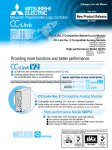
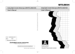
8. EXTERNAL DIMENSION DIAGRAM
[AJ65VBTCU-68ADVN/ADIN]
31 (1.22)*
41 (1.61)
67 (2.64)
3.5
(0.14)
57.5 (2.26)
DIN rail
115 (4.53)
57.5 (2.26)
16.5
(0.65)
*: This section should be 14.5mm (0.57inch) when an online connector is not installed.
Unit: mm (inch)
16
Memo
17
WARRANTY
Mitsubishi will not be held liable for damage caused by factors found not to be the cause of
Mitsubishi; machine damage or lost profits caused by faults in the Mitsubishi products; damage,
secondary damage, accident compensation caused by special factors unpredictable by
Mitsubishi; damages to products other than Mitsubishi products; and to other duties.
Country/Region Sales office/Tel
Country/Region Sales office/Tel
U.S.A
Mitsubishi Electric Automation Inc.
500 Corporate Woods Parkway Vernon
Hills, IL 60061, U.S.A.
Tel : +1-847-478-2100
South Africa
Circuit Breaker Industries Ltd.
9 Derrick Road, Spartan, Gauteng PO Box
100, Kempton Park 1620, South Africa
Tel : +27-11-977-0770
Brazil
MELCO-TEC Representacao Comercial
e Assessoria Tecnica Ltda.
Av. Paulista, 1439, cj74, Bela Vista,
Sao Paulo CEP: 01311-200 - SP Brazil
Tel : +55-11-3146-2200
China
Mitsubishi Electric Automation (China) Ltd.
No.1386 Hongqiao Road, Mitsubishi
Electric Automation Center Shanghai
China
Tel : +86-21-2322-3030
Germany
Mitsubishi Electric Europe B.V. German
Branch
Gothaer Strasse 8 D-40880 Ratingen,
Germany
Tel : +49-2102-486-0
Taiwan
Setsuyo Enterprise Co., Ltd.
6F., No.105, Wugong 3rd, Wugu Dist,
New Taipei City 24889, Taiwan, R.O.C.
Tel : +886-2-2299-2499
U.K
Mitsubishi Electric Europe B.V. UK Branch
Travellers Lane, Hatfield, Hertfordshire.,
AL10 8XB, U.K.
Tel : +44-1707-276100
Korea
Mitsubishi Electric Automation
Korea Co., Ltd.
1480-6, Gayang-dong, Gangseo-ku
Seoul 157-200, Korea
Tel : +82-2-3660-9530
Italy
Mitsubishi Electric Europe B.V. Italian
Branch
Viale Colleoni 7-20041 Agrate Brianza
(Milano), Italy
Tel : +39-039-60531
Singapore
Mitsubishi Electric Asia Pte, Ltd-Industrial
Division
307 Alexandra Road #05-01/02,
Mitsubishi Electric Building, Singapore
Tel : +65-6470-2480
Thailand
Mitsubishi Electric Automation (Thailand)
Co., Ltd.
Bang-Chan Industrial Estate No.111
Soi Serithai 54,
T.Kannayao, A.Kannayao, Bangkok
10230 Thailand
Tel : +66-2-906-3238
Indonesia
P. T. Autoteknindo Sumber Makmur
Muara Karang Selatan, Block A / Utara
No.1 Kav. No. 11,
Kawasan Industri Pergudangan,
Jakarta-Utara 14440, P.O.Box 5045,
Indonesia
Tel : +62-21-663-0833
India
Mitsubishi Electric India Pvt. Ltd.
2nd Floor, Tower A & B, Cyber Greens,
DLF Cyber City, DLF Phase-III,
Gurgaon-122002 Haryana, India
Tel : +91-124-463-0300
Australia
Mitsubishi Electric Australia Pty. Ltd.
348 Victoria Road PO BOX11,
Rydalmere, N.S.W 2116, Australia
Tel : +61-2-9684-7777
Spain
France
Mitsubishi Electric Europe B.V. Spanish
Branch
Carretera de Rubi 76-80 E-08190
Sant Cugat del Valles (Barcelona), Spain
Tel : +34-93-565-3131
Mitsubishi Electric Europe B.V. French
Branch
25, Boulevard des Bouvets, F-92741
Nanterre Cedex, France
Tel : +33-1-5568-5568
Czech Republic Mitsubishi Electric Europe B.V.-o.s.-Czech
office
Avenir Business Park, Radlicka 714/113a
CZ-158 00 Praha 5
Tel : +420-251-551-470
Poland
Mitsubishi Electric Europe B.V. Polish
Branch
ul. Krakowska 50 32-083 Balice, Poland
Tel : +48-12-630-47-00
Russia
Mitsubishi Electric Europe B.V. Russian
branch St.Petersburg office
Piskarevsky pr. 2, bld 2, lit "Sch", BC
"Benua", office 720; 195027, St.
Petersburg, Russia
Tel : +7-812-633-3497
HEAD OFFICE : TOKYO BUILDING, 2-7-3 MARUNOUCHI, CHIYODA-KU, TOKYO 100-8310, JAPAN
NAGOYA WORKS : 1-14, YADA-MINAMI 5-CHOME, HIGASHI-KU, NAGOYA, JAPAN
When exported from Japan, this manual does not require application to the Ministry
of Economy, Trade and Industry for service transaction permission.
Specifications subject to change without notice.