1
User’s Guide
Thermo Scientific
HyClone Single-Use Bioreactor
Thermo Scientific
HyClone Single-Use
Bioreactor (S.U.B.)
User’s Guide
UG003 Rev 11
Preface
Patents and Trademarks:
The Thermo Scientific HyClone Single-Use Bioreactor is covered under US patents USPN 7,384,783
and 7,682,067 and 7,487,688. Other US and international patents are pending. KleenpakTM and Pall®
are registered trademarks of Pall Corporation. SmartSite® is a registered trademark of ALARIS Medical
Systems, Inc. C-Flex® and PharMed® are registered trademarks of Saint-Gobain. Envirotainer® is a
registered trademark of Envirotainer AB. Broadley-James® and BioNet® are trademarks of BroadleyJames Corporation. Applikon® is a trademark of Applikon Biotechnology. DeltaVTM is a registered
trademark of Emerson Process Management. TruViuTM is a registered trademark of Finesse Solutions, LLC.
CelliGen® and BioFlo® are registered trademarks of New Brunswick Scientific. BIOSTAT® is a registered
trademark of Sartorius BBI Systems. Terumo® is a registered trademark of Terumo Meical Corporation.
PharmPureTM is a registered trademark of PharmaPure Tubing. All other trademarks, registered
trademarks, or logos are properties of their respective owners.
NOTE: The drawings used throughout this document are representative only and may change.▲
We have taken precautions to ensure this manual is accurate and complete. Nevertheless, readers should
remain alert to the possibility of errors and omissions. If any of the information in this manual seems
incorrect, contact Thermo Fisher Scientific for advice before proceeding. This information, including
product specifications, is subject to change without notice. Because of this, please take caution if
extracting information from this User’s Guide for use in other documentation as it will be updated with
future revisions. Please contact Thermo Scientific HyClone products technical support for the current
revision.
MANUAL NUMBER
11
REV
--
10/29/10
ECR/ECN
Date
Thermo Scientific
S.U.B. User’s Guide
Description
ii
Table of Contents
Warnings and Safety...............................................................................1
Thermo Scientific
Section 1
Single-Use Bioreactor (S.U.B.) Overview
1.1 Introduction to the Single-Use Bioreactor..........................................3
1.2 Hardware Characteristics....................................................................5
1.3 End User Supplied Components........................................................7
1.4 BioProcess ContainerTM Characteristics................................................9
1.5 Additional System Components.......................................................12
1.6 Initial Installation Instructions.........................................................13
1.7 Installation and Setup.......................................................................22
1.8 S.U.B. Operation Information.........................................................24
1.9 S.U.B. Operating Instructions..........................................................31
Section 2
Operating Information
2.1 Calibration Procedures.....................................................................39
2.2 BPC Loading Instructions (50, 100, 250 and 500 L).......................40
2.3 BPC Loading Instructions (1000 L).................................................49
2.4 BPC Loading Instructions (2000 L).................................................73
2.5 Probe Assembly................................................................................95
2.6 Sampling..........................................................................................98
2.7 Pall Kleenpak Connector Instructions............................................100
Section 3
Specifications
3.1 50 L S.U.B. Data Sheet and Specifications.....................................107
3.2 100 L S.U.B. Data Sheet and Specifications...................................117
3.3 250 L S.U.B. Data Sheet and Specifications...................................127
3.4 500 L S.U.B. Data Sheet and Specifications...................................137
3.5 1000 L S.U.B. Data Sheet and Specifications.................................147
3.6 2000 L S.U.B. Data Sheet and Specifications.................................158
3.7 Standard BioProcess Containers with
Disk Sparge Systems Data Sheet.....................................................168
3.8 Condenser System Data Sheet and Specifications...........................174
3.9 Load Cells Kit Data Sheet..............................................................178
3.10 S.U.B. Vent Filter Heater Data Sheet...........................................183
iii
Table of Contents
Thermo Scientific
Section 4
Troubleshooting..................................................................................186
Section 5
Ordering Information
5.1 Ordering Information: Disposables (BPC).....................................193
5.2 Ordering Information: Hardware...................................................194
5.3 Ordering Information: Accessories.................................................197
5.4 Ordering Information: Partial Spare Parts List................................198
5.5 Ordering Instructions.....................................................................200
5.6 Ordering/Support Contact Information.........................................200
Appendix A
Electrical Receptacle Installation Instructions.......................................201
Appendix B
Calibration of the AC-Tech variable speed drive...................................203
Appendix C
Mettler Toledo Load Cell Calibration Instructions...............................204
Single-Use Bioreactor (S.U.B.)
iv
Warnings and Safety
Warning: Read and understand operator’s manual before using this
equipment.
Thermo Scientific HyClone Single-Use Bioreactor is designed to be
operated under traditional mammalian cell culture conditions. A general
understanding of bioreactor systems and their operation is important prior
to using the system for the first time. ▲
•• Read and understand user’s manual before operating
•• Failure to do so could result in injury
Warning: Hazardous voltage inside
Disconnect power before opening. Service by trained personnel only.
Consult manual. Electrical components are designed into and required
for the proper function of the Single-Use Bioreactor (S.U.B.) The mixer
motor, motor controller, resistive heater jacket and control panel all have
electrical components. ▲
•• Risk of electrical shock and injury
•• There is potential for static charge build-up during mixing and set-up
of BPCs
Warning: Entanglement hazard
Rotating parts can cause injury. Keep hands away from moving parts. ▲
Warning: Hot surface. Do not touch.
The heating jacket is designed to heat the outer vessel wall. Normal
operating conditions generate heat and could create hot surfaces. ▲
•• Hot surface inside
•• Contact with surfaces may cause burns
•• Do not touch while in operation
Warning: Burst Hazard
Under normal operating conditions the S.U.B. BPC chamber is under
slight pressure. Normal passive venting prevents any excess of pressure
building up within the chamber. Chamber pressure and inlet line pressure
should be monitored for proper settings. ▲
•• Contents under pressure
•• Do not exceed 0.5 psi (0.03 bar) BPC pressure
•• Do not exceed 5 psi (0.34 bar) inlet pressure
•• Assure vent filter is properly positioned and working properly
Thermo Scientific
Single-Use Bioreactor (S.U.B.)
1
Warnings and Safety
Protective Earthing
Environmental
Conditions
Water Jacket
Vessel Information
Protective earthing must be verified prior to plugging the S.U.B. into any
electrical outlet. Ensure the receptacle is properly earth grounded.
••
••
••
••
Operating: 17°C to 27°C; 20% to 80% relative humidity, noncondensing
Storage: -25°C to 65°C
Installation category II (over voltage) in accordance with IEC 664
Altitude Limit: 2,000 meters
The Water Jacket S.U.B. has been designed to be operated with water as
the heat transfer medium with temperatures not exceeding 50°C (122°F)
under less than 150 psi (1 MPa) operating pressure.
NOTE: The S.U.B. BPC operating limits for temperature are 5 to 40°C.
The internal pressure should not exceed 0.5 psi. The water jacket is not
classified as a pressure vessel and is not required to be registered, inspected
and stamped with the Code U symbol per section U-1(c)2(f ) of the
ASME Boiler and Pressure Vessel Code [operating with water as the heat
transfer medium, temperature not exceeding 99°C (210°F) under less
than 300 psi (2 MPa)]. In Europe, all pressure vessels and assemblies
operating at pressures greater than 7.5 psi (50 MPa) are subject to the
Pressure Equipment Directive 97/23/EC (PED). As required by this
directive, a conformity assessment performed by the manufacture deemed
this equipment as falling below the conformity assessment category 1
(type of equipment – vessel, state of the intended fluid contents – liquid,
fluid group of the intended contents – group 2 [non-dangerous, water]).
As such, these vessels are not deemed as being subject to a conformity
assessment and are thereby only required to meet the Sound Engineering
Practice (SEP) guidelines outlined in the directive. Installation and
operation of the S.U.B. must adhere to the manufacturer’s operating
guidelines in order to ensure compliance with this assessment; to ensure
utmost safety it is recommended that all S.U.B jacket systems be operated
at 75 psi or less. If regulatory certification is deemed necessary by a
governing body or the installation is likely to require function outside
of the above mentioned parameters, a regulatory stamped jacket can be
obtained for an additional fee.
Thermo Scientific
Single-Use Bioreactor (S.U.B.)
2
Section 1.1
S.U.B. Overview
Section 1 Single-Use Bioreactor
(S.U.B.) Overview
This section covers the following information:
1.1
Introduction to the Single-Use Bioreactor
1.2
Hardware Characteristics
1.3
End User Supplied Components
1.4
BioProcess Container Characteristics
1.5
Additional System Components
1.6
Initial Installation Instructions
1.7
Installation and Setup
1.8
S.U.B. Operating Information
1.9
S.U.B. Operating Instructions
1.1 Introduction
The Thermo Scientific HyClone Single-Use Bioreactor (S.U.B.) has
been designed to be a disposable alternative to conventional stirred tank
bioreactors currently utilized in animal cell culture. Based on years of
accepted stirred tank reactor (STR) design, the S.U.B. emulates STR
scalability and operating parameters, yet it has the unique advantage
of being a completely disposable device. Ease of setup with respect to
system operation and integration into existing facilities makes the S.U.B.
an attractive alternative to its stainless steel counterpart. Critical design
parameters such as height to diameter ratios, mixer design and location,
and typical control system interfaces have been maintained. The S.U.B.
BPC is supplied sterilized by irradiation and therefore does not require
any facility hook-ups for sterilization or cleaning. A key element to the
single-use design is the plastic (polyethylene) impeller with a bearing/seal
assembly linking to an external mixer drive. Quick setup and change over
allows for faster turnover in cell culture runs over traditional reusable
systems.
The S.U.B. systems consist of three primary components:
1. Outer support container with either Electric Resistive or Water
Jacket heating systems
2. Single-Use Bioreactor BioProcess Container (BPC) and
3. Control System for agitation (Electric Resistive and Water Jacket)
and temperature (resistive only)
The outer support container is engineered and fabricated to fully support
each S.U.B. BPC and allow easy access for operation. It is a stainless steel
vessel which holds and supports the BPC. The outer support container
contains the mixing drive, silicone heating blanket (Electric Resistive) or
Water Jacket, controllers for mixing and heating (Electric Resistive), and
Thermo Scientific
Single-Use Bioreactor (S.U.B.)
3
Section 1.1
S.U.B. Overview
portable dolly. The drive shaft is detachable and reusable and is inserted
into the BPC through the mixing assembly and into the bearing port.
Load cells are offered standard on the 1000 and 2000 L S.U.B.s and are
optional for the smaller volume systems.
The BPC includes the impeller assembly, sparger, vent filter inlet/outlet
ports, probe integration ports, and filling, dispensing, and sampling
ports. Each S.U.B. BPC comes fully assembled and gamma irradiated.
The materials are fully qualified for biological product contact per USP
Class VI plastics. Each assembly is manufactured under cGMP and is
supported by qualification and validation information. No reuse cleaning
or sterilization validations are required as the BPC is provided gamma
irradiated. Innovative, proprietary technology allows for the integration
of the mixing shaft, pH and dissolved oxygen probes, and the resistive
temperature detector (RTD). The probe and temperature interfaces are
comparable to traditional systems with the design allowing for simple,
aseptic connections. Integrated disposable spargers are built into the
S.U.B. BPC through universal ports.
The control system encompasses both incorporated and end-user supplied
components. Controls for temperature (resistive only) and agitation
are integrated into the S.U.B., with pH/dissolved oxygen (DO) probes
and controls being supplied by the user. Water Jacket systems require a
temperature control unit selected and supplied by the end user. This User’s
Guide covers the setup, operation, maintenance and troubleshooting of
all retrofit S.U.B. systems in the following volumes – 50, 100, 250, 500,
1000 and 2000 L.
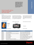
Figure 1.1. Single-Use Bioreactor
Thermo Scientific
Single-Use Bioreactor (S.U.B.)
4
Section 1.2
Hardware Characteristics
1.2 Hardware
Characteristics
System Features
Agitation
The Single-Use Bioreactor is designed for system mobility and easy
disposable integration while utilizing a straightforward operator interface.
Hardware drawings and specifications tables specific to volume can
be found in Section 3. The following sections describe the hardware
components of the S.U.B.
Stirring speed is adjusted by using the keypad interface on the control
panel. The agitation control interface utilizes a digital display to indicate
stirring speed in units of revolution per minute (RPM). Power is supplied
to the motor by a two position power switch. The up and down arrows on
the agitation keypad adjust the stirring speed.
Bioreactor
Control System
The Single-Use Bioreactor is designed to integrate with existing bioreactor
control systems in their numerous configurations. The S.U.B. control
system manages the selected process parameters of agitation and
temperature. Parameters of pH and DO control must be managed by an
external controller supplied by the end user.
Exhaust Vent
Filter Heater
An optional exhaust vent filter heater is available for increased longevity
of the exhaust filter on the S.U.B. BPC. Heating the filter sufficiently to
eliminate the formation of condensation is an effective means of reducing
the risk of fouling of the filter membrane. The heater is factory preset to
operate between 40-50°C, but can easily be adjusted to the demand of the
application. Temperature settings above 60°C are not recommended.
Condenser System
The Condenser System is recommended for 2000 L S.U.B. use and is also
available as optional hardware for smaller systems. It cools exhaust gases
and re-circulates the condensate into the bioreactor.
Temperature
The S.U.B. can be operated within the temperature range from ambient to
40°C. For resistive heater systems, temperature setpoints can be adjusted
via the temperature controller located on the front panel of the S.U.B.
control box. This controller is preprogrammed to avoid overshoot during
heat up and maintain a target temperature of +/-0.5ºC based on the set
value display. The process temperature is measured by means of a supplied
RTD (pt-100) that is inserted into the thermo-well of the S.U.B. BPC.
Water Jacket system temperature control is maintained through the
temperature control unit (TCU) supplied by the end user.
Thermo Scientific
Single-Use Bioreactor (S.U.B.)
5
Section 1.2
Hardware Characteristics
Heating Performance
Heating times for the S.U.B. systems vary based upon operating liquid
volume and temperature, ambient or heating fluid temperature, sparge
rate, and mixing rate. Users should adjust process liquid staging and
seeding strategies to the unique aspects of the S.U.B. Process controllers
and heaters in resistive heating systems are designed to provide optimum
heat transfer and to minimize heat up times, while maintaining the
material integrity of the polymer film construction of the S.U.B. BPC.
Refer to Section 1.8 for expected heating times.
External Control
Users can choose to bypass the temperature and mixing speed control
system provided with the S.U.B. and utilize existing bioreactor controllers.
Refer to Section 1.8 for more details.
Load Cells
Load cells are standard on the 1000 and 2000 L S.U.B. hardware and
optional for the smaller S.U.B. volumes. Load cell kits can be installed at
the factory or can be added later by a certified service technician. The load
cell kit comes with three load cells, summing block, wiring and display
with a choice of several data interfaces.
Load cells arrive uncalibrated; it is recommended that the load cell
manufacturer or a qualified technician calibrate these systems on site.
Thermo Scientific
Single-Use Bioreactor (S.U.B.)
6
Section 1.3
End User Supplied Components
1.3 End User
Supplied
Components
pH and Dissolved
Oxygen (DO) Probes
The following table shows the length and diameter requirements for
traditional sensors (probes) that can be integrated into the S.U.B. These
requirements are based on the necessary insertion depth of the probe when
used with the probe ports. Note: The presence of a properly positioned
O-ring on the probe is critical for use with the S.U.B.
Recommended pH/DO Probes for use with the S.U.B.
Probe Lengths (from O-ring to tip) Must Not Exceed 235 mm
O-ring to probe tip
Print/Lit. Actual
Length
Length
(mm)
(mm)
Probe
Part Number
Diameter
(mm)
Thread
Type
AppliSens DO
Z010023520
12
13.5 PG
235
235
12
13.5 PG
235
235
12
13.5 PG
215
215
12
13.5 PG
195
219
Applisens pH
Mettler Toledo DO
Mettler Toledo pH
Z001023510,
Z001023511
InPRO 6800/12/220, PN 52200966
405-DPAS-SC-K8S/225,
PN 104054481IG
Broadley-James DO
D140-B220-PT-D9
12
13.5 PG
215
214
Broadley-James pH
F-635-B225-DH
12
13.5 PG
225
219
Finesse DO
DOS-OFF-VP-225
12
13.5 PG
225
220
Finesse pH
PHS-EFP-K8-225
12
13.5 PG
225
220
NOTE: Consult probe manufacturer’s Web site for appropriate probe cable connection and part number. ▲
Table 1.1. Manufacturers and models of S.U.B. compatible pH/DO probes.
Controllers
Thermo Scientific
Many bioreactor controllers can be adapted for use with the S.U.B. Table
1.2 lists several companies offering control systems or custom solutions
that will work well when controlling S.U.B. parameters such as dissolved
oxygen (DO) and pH. Alternatively, users seeking advanced control
functionality and data logging capabilities for parameters of pH, DO,
temperature, agitation and others, can determine their own preferred
approach in order to interface these parameters with a single controller.
Please refer to the Equipment Turnover Package (ETP) supplied with
each hardware system for electrical schematics. Discussions regarding the
Single-Use Bioreactor (S.U.B.)
7
Section 1.3
End User Supplied Components
integration of specific bioreactor control systems for advanced control
functionality should be directed though technical support staff for Thermo
Scientific HyClone products and the associated controller manufacturer.
Controller Manufacturer
ABEC
Applikon
Allen-Bradley
Bellco
Broadley-James
Das Gip
Emerson
Finesse
Honeywell
New Brunswick Scientific
PendoTech
Sartorius Stedim Biotech
Siemens
Thermo Systems
Table 1.2. Some Controller Manufacturers of S.U.B. compatible pH/DO
controllers.
Note: The S.U.B. will work well with any of the various control system
platforms, such as PLC, PC, DCS or proprietary operating system based
controllers.
Thermo Scientific
Single-Use Bioreactor (S.U.B.)
8
Section 1.4
BioProcess Container Characteristics
1.4 BioProcess
Container
Characteristics
Single-Use Bioreactor
BPC Features
The cell culture itself is contained inside the Single-Use Bioreactor BPC.
The chamber is manufactured from CX5-14 film which is a co-extruded
structure specifically designed for biopharmaceutical process usage. All
materials are qualified for a broad range of physical, mechanical, biological
and chemical compatibility requirements. (Refer to CX5-14 data in our
BPC Catalog, contact your sales representative for a copy). The bioreactor
BPC is pre-sterilized using validated gamma irradiation processes.
Operating Pressure
The S.U.B. BPC does not operate as a closed system, as it has both inlet
and exhaust filters that are utilized to maintain an environment for cells
to grow without concern for contamination. However, conditions can be
encountered when gas inlet flow rate may exceed exhaust flow rate. This
may be encountered in the unlikely event of a pressure regulator failure on
a gas feed, or when excessive foaming creates conditions of vent blockage.
The S.U.B. BPC is not rated as a pressure vessel (gas pressure should
not exceed 0.5 psi within the BPC). Custom BPCs can be ordered with
an optional disposable pressure transducer for monitoring the pressure
within the S.U.B. (supplied standard with 1000 and 2000 L systems).
Working Volume
Each S.U.B. is designed for a working volume range. The minimum
working volume and the rated working volume are listed in the
specification tables provided in Section 3. The total volume listed includes
the headspace needed for proper aeration and gas management. Actual
working volumes should not exceed the indicated rated working volumes.
In addition, working volumes less than the minimums listed can result in
damage to the S.U.B. BPC and hardware malfunction.
Draining and Harvest
Thermo Scientific
The S.U.B. is equipped with a bottom drain line that allows for liquid
harvest by means of peristaltic pump. Connection of the bottom drain
line can be accomplished by use of a tubing welder or the aseptic
connection of quick connect or fitting that is provided. Manipulation of
the S.U.B. BPC as the last few liters of media is removed can minimize
liquid hold-up within the S.U.B.
Single-Use Bioreactor (S.U.B.)
9
Section 1.4
BioProcess Container Characteristics
Aeration
Gas to liquid mass transfer in cell culture bioreactors is controlled by the
solubility of the gas in the liquid, its distribution, and the temperature
and pressure. Direct air sparging is a way of providing for the oxygen
requirements of mammalian cell cultures. The standard S.U.B. bag
incorporates a unique disposable dual sparging design that allows for
optimal aeration of the culture process and effective CO2 stripping.
Aseptic Connections
Multiple aseptic connection options exist for S.U.B. users. The standard
BPCs include tubing welder sections, quick connects and Pall Kleenpak
connections. The S.U.B. BPC is designed with various lengths and
dimensions of thermoplastic tubing for the purpose of addition to and
dispensing from the S.U.B. BPC. Refer to Ordering Information in
Section 3 for custom end treatment options.
Sampling
The S.U.B. is equipped with a small volume sample port that is adjacent
to the S.U.B. BPC thermo-well. This small diameter silicone dip tube of
6” length (15.24 cm) allows low void volume samples to be taken for cell
viability and density, as well as analyte analysis. This dip tube is supplied
with an aseptic luer lock connector (SmartSite) that allows for direct
sampling or attachment of various sampling manifolds by use of standard
luer lock connection. Alternatively, manifolds can be welded onto the.
C-Flex sample line by tubing welder.
BPC drawings and standard configuration tables specific to volume can be
found in Section 3.
Thermo Scientific
Single-Use Bioreactor (S.U.B.)
10
Section 1.4
BioProcess Container Characteristics
BPC Features
2
3
4
1
1
1
2
2
3 4
3
4
11
5
5
5
6
9
10
7
8
9
10
Figure 1.2. Typical 50 L, 100 L
and 250 L BPC Schematic
6
6
10
3
7
8
10
7
8
10
10
9
Figure 1.3. Typical 500 L and 1000 L BPC
Schematic
Figure 1.4. Typical 2000 L BPC
Schematic
Part
Description
1.
Exhaust Vent Filter
Single-use capsule filter for exhaust gas exchange
2.
Gas Overlay Port
Protected by gas filter
3.
Ports
For addition of media and other liquids
4.
Seal/Bearing Assembly
Links with mixer motor and allows impeller to turn while
retaining integrity of the S.U.B. BPC
5.
Impeller
Injection molded plastic; Linked to seal/bearing assembly by C-Flex tubing contact material of the shaft
6.
Ports with Kleenpak Connectors
For integration of standard 12 mm monitoring pH and DO
probes
7.
Temperature RTD Port
For integration of temperature probe while retaining
integrity of the S.U.B. BPC
8.
Sampling Port
For needleless sampling or connection to sampling manifold
9.
Drain Port
Used when draining the S.U.B.
10.
Gas Sparge Lines
Sparge integrated into the chamber; Protected by gas filters
11.
Condenser System Bag
Integrates with chill plate to remove condensate from
exhaust
Table 1.3 Key to Figures 1.2, 1.3 and 1.4
Thermo Scientific
Single-Use Bioreactor (S.U.B.)
11
Section 1.5
Additional System Components
1.5 Additional
System Components
Probe Integration
The probe assembly is an innovative disposable design to package user
supplied pH and DO probes for sterilization and to aseptically connect
them to the S.U.B. BPC. The probe assembly (Figure 1.5) includes the
following components:
1. Molded bellows cover
2. Threaded probe adaptor
3. Pall Kleenpak Connector (KPCHT Series - high temperature)
4. Cable ties
2
4
1
4
3
Figure 1.5. Probe Assembly
Required and Optional
Accessories
Thermo Scientific
To assist in the operation of the Single-Use Bioreactor the following
additional accessories are available (see Section 3 for ordering
information):
•• Heavy duty tubing clamps - sold separately
Required (typically four or five)
•• Autoclave tray for probe kits (stainless steel)
Required (minimum of one required) - The autoclave support
tray provides an inclined fixture for two probes during
autoclaving to minimize stress on the probes and to prevent
collapse of the silicone bellows.
•• Sampling manifold with luer lock
Optional
•• S.U.B. temperature sample port (for RTD calibration/validation)
Optional
•• Vent Filter Heater System
Optional - For users who require additional protection for the
exhaust vent filter on the standard S.U.B. BPC. Consists of
filter heater, programmable controller and power cord.
•• Condenser System
Recommended for 2000 L S.U.B. Optional on smaller systems.
•• Load cells
Standard on 1000 and 2000 L S.U.B.s. Optional on smaller
sizes - Consists of three load cells, summing block, wiring and
display with choice of several data interfaces.
Single-Use Bioreactor (S.U.B.)
12
Section 1.6
Initial Installation Instructions
1.6 Initial Installation
Instructions
Hardware Shipment
and Setup
The Single-Use Bioreactor hardware is shipped directly from the
manufacturer and will arrive crated. For unpacking instructions and
detailed contents of the crate, please refer to the instructions specific to the
S.U.B. volume. Be sure to follow the unpacking instructions provided and
retain all packaging materials.
50 L, 100 L, 250 L and
500 L Hardware
Uncrating
The S.U.B. hardware should arrive with the following items:
•• Outer support container (platform, tank and control panel)
•• Drive shaft, RTD, probe shelf and brackets (4) and standard tool set
(spanner wrench and torque wrench)
•• ETP - located on CD provided with hardware
1.
2.
3.
4.
5.
Remove crate lid first
Remove side wall(s)
Remove the tie-down straps
Remove any/all blocks on crate floor
Remove S.U.B. carefully using forklift/manually by lifting via the
bottom of the cart frame, not the casters
6. Ensure no damage occurred during shipping
Contact your Sales Representative immediately if damage has occurred.
1000 L and 2000 L
Hardware
Thermo Scientific
Detailed instructions for crating, uncrating and assembly for the 1000 and
2000 L S.U.B. units can be found in the Integrator Reference Guide.
Single-Use Bioreactor (S.U.B.)
13
Section 1.6
Initial Installation Instructions
Site Preparation
Electrical Connections
The S.U.B. hardware cannot be used on circuits equipped with GFCI
circuit protection because of the potential for nuisance tripping. The
electrical plug on the S.U.B. is a connector that offers a secure ground.
These connectors meet the electrical safety codes for portable equipment
and are International Electrical Code (IEC) rated (meet IEC standard
60309). This plug serves to provide electrical ground prior to power
connection. The supplied electrical receptacle should be hardwired into
the facility by a qualified electrical technician; for US installations the
receptacle will require the use of an adapter mounting plate (supplied)
which will fit into a ‘two gang’ box. For additional information on the
adapter mounting plate, please see the ETP. Alternatively, the system
can be hardwired directly into the facility. NOTE: The yellow plug and
receptacle are for 120VAC and the blue are for 240VAC S.U.B.s.
Outer Support Container
Preparation
Each outer support container is shipped directly from the manufacturer
and arrives with various safety mechanisms in place. Please follow the
guidelines below to setup the Single-Use Bioreactor upon arrival.
Warning: Any procedures that require the control box to be open
should be performed with the main electrical disconnect in the locked
out position and all power sources removed from the control box. For
operator safety, secure the location of the S.U.B. outer support container
by disabling the swivel casters before servicing. ▲
For 50 L, 100 L, 250 L and
500 L Volume Electric
Resistive Heating
Systems
Thermo Scientific
1. S.U.B. units are shipped with the electrical breakers in the OFF
position to prevent accidental activation of the heaters during
hardware installation. NOTE: The heater should only be enabled
when a liquid filled BPC is present. Using a flat head screwdriver,
open the control box and locate the breakers for the PID temperature
controller (middle of top row) and heater (located in middle of lower
row) (Figure 1.6). These breakers should be in the upper ON position
during operation. For electrical schematics, please refer to the ETP
which is located on CD provided with hardware.
2. Verify position of the three-way motor controller switch–it should
be in the middle position. For reference, the middle position is
to enable the speed control keypad, the top position is for 0-10V
controllers and the bottom is for 4-20mA controllers. Verify position
of the two position temperature control toggle switch–it should be
in the up position (for reference, the upper position enables the PID
temperature controller)..
Single-Use Bioreactor (S.U.B.)
14
Section 1.6
Initial Installation Instructions
3. Close the control box and lock the panel using a screwdriver before
continuing.
4. To unlock the load cells, refer to Load Cell Preparation instructions
below.
Temperature
Controller
Breaker
Heater Breaker
wired in 50, 100
and 500 L only
Heater Breaker
wired in 250 and
500 L only
Motor Controller
Switch (3-way)
Temperature
Controller
Switch (2-way)
Figure 1.6 Control Box for 50, 100, 250 and 500 L Electric Resistive Heater S.U.B.
Load Cell Preparation
Thermo Scientific
5. For S.U.B. hardware units purchased with factory installed load cells,
the load cells are shipped in the locked position (centering washer
and nut are threaded up) for equipment protection (Figure 1.7 and
1.8). A 15/16” open-box wrench is recommended for unlocking the
load cells. To unlock the load cells, loosen the centering washer and
nut (5/8” nut) until the nut is threaded down on the hold-down bolt
about half way. Next, loosen the jam nut on the base plate until the
jam nut and centering washer/nut meet. Tighten both nuts together.
Using an open-end wrench, loosen the hold down bolt (by moving
it upward) to provide clearance below and above the cutout in the
top plate (Figure 1.61 – Section A-A). The clearance around (above
and below) this nut should be from 1/8” to 3/16”. Once the proper
clearance has been achieved, retighten the jam nut..
.
.
.
.
Single-Use Bioreactor (S.U.B.)
15
Section 1.6
Initial Installation Instructions
Figure 1.7
.
.
.
.
.
.
.
.
.
.
.
TOP OF BOLT (NOT A NUT)
JAM NUT
HOLD DOWN BOLT
Figure 1.8 Unlocking Load Cells
6. At this point, the S.U.B. hardware is ready to be prepared for a cell
culture run.
7. CAUTION: Do not move unit, especially when filled, while load
cells are unlocked as this can damage the load cells.
8. For load cell calibration refer to Appendix C
For 50 L, 100 L, 250 L and
500 L Volume Water
Jacket Systems
Thermo Scientific
1. Before beginning, refer to electrical schematics included with the
ETP which is located on CD provided with hardware.
2. Using a flat headed screwdriver, open the control box. Verify position
of the three-way motor controller switch–it should be in the middle
position (Figure 1.9).
3. Close the control box and lock the panel using a screwdriver before
continuing.
4. For S.U.B. hardware units purchased with factory installed load cells,
the load cells are shipped in the locked position (threaded up) for
equipment protection. Refer to Load Cell Preparation instructions
above.
5. At this point, the S.U.B. hardware is ready to be prepared for cell
culture run.
Single-Use Bioreactor (S.U.B.)
16
Section 1.6
Initial Installation Instructions
Motor Controller
Switch (3 way)
Figure 1.9 Control Box for 50, 100, 250 and 500 L Water Jacket S.U.B.
1000 L Outer Support
Container Preparation
Thermo Scientific
1. For resistive systems: The S.U.B. units are shipped with the electrical
breakers in the OFF position to prevent accidental activation of
the heaters during hardware installation. NOTE: The heater should
only be enabled when a liquid filled BPC is present. Using a flat
head screwdriver, open the control box and locate the breakers for
the Proportional Integral Derivative (PID) temperature controller,
heaters, pressure sensor and load cells (middle of top row) (Figure
1.10). These breakers should be in the upper ON position during
operation. For electrical schematics, please refer to the ETP which
is located on CD provided with hardware. NOTE: The heater and
PID breakers are present in the Water Jacket versions, but nonoperational.
2. Verify position of the three-way motor controller switch–it should be
in the middle position (for reference, the middle position is to enable
the speed control keypad).
3. For resistive systems: Verify position of the two position temperature
control toggle switch–it should be in the up position for reference,
the upper position enables the PID temperature controller. .
NOTE: This switch is present in the Water Jacket versions, but nonoperational.
4. Close the control box and lock the panel using a screwdriver before
continuing. .
.
.
Single-Use Bioreactor (S.U.B.)
17
Section 1.6
Initial Installation Instructions
Temperature
Controller
Breaker
Heater
Breakers (3)
Pressure Sensor
Display
Load Cell
Motor Controller
Switch (3-way)
Temperature
Controller
Switch (2-way)
Figure 1.10 Control Box for 1000 L S.U.B. Resistive
Temperature
Controller
Breaker
Heater Breakers (3)
(no heater, nonoperational)
Pressure Sensor
Display
Load Cell
Motor Controller
Switch (3-way)
Temperature
Controller
Switch (2-way)
Figure 1.11 Control Box for 1000 L S.U.B. Jacketed
Thermo Scientific
Single-Use Bioreactor (S.U.B.)
18
Section 1.6
Initial Installation Instructions
Load Cell Preparation
5. For S.U.B. hardware units purchased with factory installed load cells,
the load cells are shipped in the locked position (centering washer
and nut are threaded up) for equipment protection (Figure 1.12 and
1.13). A 15/16” open-box wrench is recommended for unlocking the
load cells. To unlock the load cells, loosen the centering washer and
nut (5/8” nut) until the nut is threaded down on the hold-down bolt
about half way. Next, loosen the jam nut on the base plate until the
jam nut and centering washer/nut meet. Tighten both nuts together.
Using an open-end wrench, loosen the hold down bolt (by moving
it upward) to provide clearance below and above the cutout in the
top plate (Figure 1.65 – Section A-A). The clearance around (above
and below) this nut should be from 1/8” to 3/16”. Once the proper
clearance has been achieved, retighten the jam nut.
Figure 1.12
TOP OF BOLT (NOT A NUT)
JAM NUT
HOLD DOWN BOLT
Figure 1.13 Unlocking Load Cells
6. At this point, the S.U.B. hardware is ready to be prepared for a cell
culture run.
7. CAUTION: Do not move unit, especially when filled, while load
cells are unlocked as this can damage the load cells.
8. For load cell calibration refer to Appendix C
Thermo Scientific
Single-Use Bioreactor (S.U.B.)
19
Section 1.6
Initial Installation Instructions
2000 L Outer Support
Container Preparation
Load Cell Preparation
1. Using a flat head screwdriver, open the control box and locate the
breakers for the pressure sensor, continuous power outlets non
E-stoppable (2), continuous power outlets E-stoppable (2) (Figure
1.14). These breakers should be in the ON position during operation
(blue indicator pressed in). For electrical schematics, please refer to
the ETP which is located on CD provided with hardware.
2. Verify position of the three-way motor controller switch–it should be
in the middle position (for reference, the middle position is to enable
the speed control keypad).
3. Close the control box and lock the panel using a screwdriver before
continuing.
4. For S.U.B. hardware units purchased with factory installed load cells,
the load cells are shipped in the locked position (centering washer
and nut are threaded up) for equipment protection (Figure 1.15 and
1.16). A 15/16” open-box wrench is recommended for unlocking the
load cells. To unlock the load cells, loosen the centering washer and
nut (5/8” nut) until the nut is threaded down on the hold-down bolt
about half way. Next, loosen the jam nut on the base plate until the
jam nut and centering washer/nut meet. Tighten both nuts together.
Using an open-end wrench, loosen the hold down bolt (by moving
it upward) to provide clearance below and above the cutout in the
Motor Controller
Switch (3-way)
Pressure
Outlet 240 VAC
Continuous Power
Non E-Stoppable
Outlet 240 VAC
Continuous Power
E-Stoppable
Figure 1.15 Control Box for 2000 L Jacketed S.U.B.
Thermo Scientific
Single-Use Bioreactor (S.U.B.)
20
Section 1.6
Initial Installation Instructions
top plate (Figure 1.16 – Section A-A). The clearance around (above
and below) this nut should be from 1/8” to 3/16”. Once the proper
clearance has been achieved, retighten the jam nut.
Figure 1.15.
TOP OF BOLT (NOT A NUT)
JAM NUT
HOLD DOWN BOLT
Figure 1.16 Unlocking Load Cells
6. At this point, the S.U.B. hardware is ready to be prepared for a cell
culture run.
7. CAUTION: Do not move unit, especially when filled, while load
cells are unlocked as this can damage the load cells.
8. For load cell calibration refer to Appendix C
Thermo Scientific
Single-Use Bioreactor (S.U.B.)
21
Section 1.7
Installation and Setup
1.7 Installation and
Setup
Outer Support Container
Preparation
All manual movements of mobile S.U.B. hardware (does not include .
2000 L S.U.B.) should be over smooth surfaces with the S.U.B. empty
and disconnected from all power and gas/feed sources. All load cells must
be fully locked down. Refer to the appropriate subsection within Section 3
of this User’s Guide for graphics illustrating the control panel interface for
the appropriate hardware.
1. Verify facility electrical supplies are sufficient to support the power
requirements of the S.U.B. and ancillary components such as
controllers or pumps.
2. Locate the outer support container in the area for the cell culture run.
3. If monitoring the volume, the unit may be located on a scale if load
cells are not utilized. Other applications may measure all liquids
going in and coming out.
4. Level the platform by disabling the swivel casters on the bottom of
the outer support container. This is accomplished by threading the
leveling pads (at the center of each caster) to the floor.
5. Verify the location of the pH/DO controllers and assure cable/tubing
lengths are satisfactory.
WARNING: ELECTRICAL SHOCK. ▲
6. Verify the main power is off and the emergency stop is pulled out.
NOTE: THE EMERGENCY STOP DISCONNECTS ALL POWER
TO THE SYSTEM. AN ALARM BUZZER WILL SOUND WHEN
THE EMERGENCY STOP IS ACTIVATED. ▲
7. Verify that the main motor power switch is in the off position.
8. Connect all electrical plugs to facility power. NOTE: 120 VAC
- 250 L S.U.B. to be connected to a dedicated 20A circuit. Refer to
hardware/electrical labels and schematics to ensure proper electrical
voltage is connected to the S.U.B. The main power switch can now
be turned on.
9. Resistive heating systems - Verify the temperature controller is off
(the display should be flashing in the standby position).
10. Water Jacket Systems - Connect water inlet and outlet lines from
temperature control unit quick connects to the jacket (Figure 1.17).
For 50 L through 500 L and 2000 L S.U.B. systems, the inlet is
typically on the left side if facing the connectors. For the 1000 L
S.U.B., the inlet is the lower connection and the outlet is the upper.
Thermo Scientific
Single-Use Bioreactor (S.U.B.)
22
Section 1.7
Installation and Setup
Figure 1.17 Water Jacket Connection
Air Line Preparation
Porous Frit Sparge
Figure 1.18 Frit Spage line holder
See Table 1.6 for recommended flow rates. The operating pressures at the
level of the S.U.B. are of primary importance and these values must be
adhered to. Please note flow rates in the graphics include both half and
full volume applications.
If you will be using a porous frit sparge in your S.U.B. bag, whether alone
or in a dual sparge setup, we recommend using the frit sparge line support
(Figure 1.18) for S.U.B. sizes 250 L and smaller. Simply attach this line
support underneath the tank directly below where the porous frit sparge
will be placed. This support piece holds the sparge gas tube vertically so
that the frit sparge itself is oriented in the vertical position for maximum
sparge effectiveness. Spring-loaded screws permit a simple sliding of the
holder clip onto the tank bottom. With the frit sparge holder attached to
the tank, the sparge line can be wound through the coil of the holder to
keep the sparge oriented properly.
WARNING: The S.U.B. BPC is not rated as a pressure vessel. The BPC
should not be allowed to become tight during inflation or operation. Gas
pressure in the BPC should not exceed 0.5 psi (0.03 bar) at any time.
Conditions of over pressure may result in BPC damage or personal injury.
For reference the BPC will appear to be tight at 0.1 psi (0.007 bar). ▲
Thermo Scientific
Single-Use Bioreactor (S.U.B.)
23
Section 1.8
S.U.B. Operation Information
1.8 S.U.B. Operation
Information
BioProcess Container
Preparation and
Loading
BPC Handling
Instructions
Each outer support container is designed for a specific Single-Use
Bioreactor BPC. Confirm the correct volume BPC is being used for
the corresponding volume outer support container. Sections 2.3 and
2.4 outline the installation and setup of the different volume S.U.B.
BPCs–please adhere to these instructions in the order in which they are
presented.
Take care if using a sharp object when opening outer polybags to avoid
damaging the S.U.B. bag. When placing bags in containers, do not drag
bag over corners or sharp objects. Do not lift the bag by the corners or top
seams. Carefully coil tubing on top of bag to prevent puncturing bag with
cable ties or clamps. Use cushioning between tubing and bag in storage
and transport.
BPC Operating
Information
Aseptic Line
Connection
The most common recommended process for making connections to the
tubing lines is with an aseptic tubing fuser such as those in Table 1.4.
NOTE: Other connection options are available as a custom S.U.B. BPC
assembly.
Following the recommended tubing welder operating instructions,
successful connections can be obtained for filling, supplementing,
sampling, or dispensing from the S.U.B. BPC as needed.
Commonly Used Tubing Welders for Aseptic Connections
Brand
Model/die set
Tubing Size ID–OD
Tubing
Material
Terumo
SCD-IIB (std)
1/8 - 1/4” (3.18 - 6.35 mm)
C-Flex
Wave
STF-IRc (1/4” [6.35 mm])
1/8 - 1/4” (3.18 - 6.35 mm)
C-Flex
Wave
STF-IRc (7/16” [11.11 mm])
1/4 - 7/16” (6.35 - 11.11 mm)
C-Flex
Wave
STF-IRc (5/8” [15.88 mm])
3/8 - 5/8” (9.53 - 15.88 mm)
C-Flex
Wave
STF-IRc (3/4” [19.05 mm])
1/2 - 3/4” (12.7 - 19.05 mm)
C-Flex
Table 1.4 Some tubing welders for S.U.B. aseptic connections
Thermo Scientific
Single-Use Bioreactor (S.U.B.)
24
Section 1.8
S.U.B. Operation Information
Working Volume
Each S.U.B. is designed for a working volume range. The minimum working volume
and the rated working volume are listed in the specification table (see Section 3).
The total volume listed includes the headspace needed for proper aeration and gas
management. Actual working volumes should not exceed the indicated rated working
volumes by greater than 10 percent. In addition, working volumes less than 50
percent of the rated volume can result in damage to the S.U.B. BPC and hardware.
Aeration
The standard S.U.B. bag is designed with special spargers that produce very
efficient mass transfer of oxygen and typically will require much less gas inflow
than conventional spargers. Gas inflow, in fact only need be limited to prevent
foam generation and excessive pressure within the BPC. Gas flow rates supplied
as overlay should also be reduced as much as possible or eliminated; this will
minimize both liquid evaporation and demand on the exhaust filter. Ideally this
will reduce the likelihood that gas inflows will exceed gas outflow of the system and
reduce the occurrence of foam in the headspace that may plug the exhaust filter.
Exhaust vent filter
The exhaust vent filter used on the 50 L - 1000 L S.U.B. is a Pall KA3 series
filter utilizing hydrophobic PVDF membranes. These filters can be oriented
in two directions 1) normal orientation with the flow arrow on the filter
housing pointing away from the BPC and 2) reverse orientation with the flow
arrow pointing toward the BPC. In the normal orientation, the filter has the
maximum filter capacity; however the side-vents are positioned on the sterile
side of the membrane. Condensate removal in this orientation requires the use
of a vent filter heater. If the orientation is reversed, the filter capacity is reduced
slightly; however, the side-vents are now on the non-sterile side, allowing
condensate to be removed with a syringe (vent heater is optional). The standard
S.U.B. BPC is supplied with the filter in the reversed orientation. NOTE:
If normal orientation is desired, this must be specified upon ordering and is
considered a custom request. It is important during operation the filter media
be free of condensate in order to maximize the capacity of the vent filter.
To drain the condensate from the outer housing of the vent filter, do the following:
1. Turn the molded fitting of the lower side vent counterclockwise.
2. Twist the side vent back and forth slightly to release the seal on the
O-ring inside the side vent.
3. Attach a needleless luer lock syringe to the lower side vent and remove
the condensate.
For users with more demanding applications, an optional vent filter heater
can be used (see Section 5.3 for filter heater ordering information).
The exhaust vent filters used on the 2000 L S.U.B. are Meissner UltraCap
series filters utilizing hydrophobic PVDF membranes. These filters are
provided in normal orientation with the flow arrow on the filter housing
pointing away from the BPC. In the normal orientation, the filter has the
Thermo Scientific
Single-Use Bioreactor (S.U.B.)
25
Section 1.8
S.U.B. Operation Information
maximum filter capacity. No side vents are provided; condensate must be
managed by use of the condenser system or vent filter heater.
Sampling
The S.U.B. is equipped with a small volume sample port that is part of
the S.U.B. BPC thermo-well. This small diameter (1/16 x 3/16” [1.59
x 4.76 mm]) silicone dip tube of 6” (15.24 cm) length allows low void
volume samples to be taken for cell viability and density, as well as analyte
analysis. This dip tube is supplied with an aseptic luer lock connector
(SmartSite) that allows for direct sampling or attachment of various
sampling manifolds by use of standard luer lock connection. Alternatively,
manifolds can be welded onto the C-Flex sample line (1/8 x 1/4” [3.18 x
6.35 mm]) by tubing welder. For recommended systems for fluid transfer,
see data sheet 016 (contact your sales representative for a copy).
WARNING: Gas pressure within the S.U.B. BPC headspace should not
exceed 0.5 psi (0.03 bar) at any time. Conditions of over pressure may
result in BPC damage or personal injury. ▲
Operating Pressure
The S.U.B. BPC is not operating as a closed system, as it has both inlet and
exhaust filters that are utilized to maintain a sterile environment for cells
to grow without concern for contamination. However, conditions can be
encountered when gas inlet flow rate may exceed exhaust flow rate. This may
be encountered in the unlikely event of the failure of a pressure regulator on
a gas feed, or when excessive foam within the bioreactor creates conditions of
vent blockage. The S.U.B. BPC is not rated as a pressure vessel. All gas supplied
to the bioreactor controller must be regulated to a pressure not to exceed
manufacturer’s recommendations (typically 10 psi (0.69 bar). Gas pressure in
the S.U.B. BPC headspace should not exceed 0.5 psi (0.03 bar) at any time. •• More demanding applications may warrant an optional exhaust vent
heater (See Section 5.3).
•• If foaming is excessive in your cell culture process, it is best to reduce
the operating volume of the process to 80% of maximum rated working
volume of the S.U.B. system being used to provide greater head space
volume.
•• Disposable pressure transducers are available on custom S.U.B.
configurations and are standard on the 1000 L and 2000L systems. This
technology combined with high-level control systems common with
industrial applications can regulate gas pressure within the confines of the
S.U.B.
Extensive cell culture testing has not found an occurrence of overpressure
sufficient to create a containment breach. Development testing of the S.U.B.
BPC system has shown that in conditions of excessive pressure the polymer
bag will fail at the upper regions of the chamber where it is unsupported by the
outer support container, minimizing the likelihood of the loss of bulk liquid.
Thermo Scientific
Single-Use Bioreactor (S.U.B.)
26
Section 1.8
S.U.B. Operation Information
Agitation
The agitator should not be operated at volumes less than the stated
minimum volume. Stirring speed is adjusted by using the keypad interface
on the control panel. The agitation control interface utilizes a red LED
digital display to indicate stirring speed in units of revolution per minute
(RPM). Power is supplied to the motor by a two position power switch
that is illuminated in green when turned to the ON position (right
position). The up and down arrows on the agitation keypad adjust the
stirring speed. Due to the auto-restart capabilities of the S.U.B., the green
start button on the keypad has been disabled; however the red stop button
on the keypad is active. If the red stop button has been used to stop the
motor, the controller can be reset and agitation restarted by using the
main motor toggle switch on the left side of the control panel. Dispense and Harvest
The S.U.B. is equipped with a bottom drain line that allows for liquid
harvest by means of peristaltic pump. Connection of the bottom drain line
can be accomplished by use of a tubing welder or the aseptic connection of
1/4” - 3/8” (6.35 - 9.53 mm) quick connect that is provided. For S.U.B.s
50 L to 1000 L, the bottom drain exits the S.U.B. BPC at the lowest
vertical position on the side of the S.U.B. This allows for easy access for
the user and minimizes the accumulation of cells in the area of the drain
during the cell culture run. Manipulation of the S.U.B. BPC as the last few
liters of media drain will minimize liquid hold-up within the S.U.B. The
2000 L S.U.B. is provided with a 1” style bottom drain near the center line
of the tank bottom.
Hardware Operating
Information
Temperature (Electric
Resistive Heating
Systems)
Temperature setpoints can be adjusted via the temperature controller
located on the front panel of the S.U.B. control box. This controller is
preprogrammed to avoid overshoot during heat up and maintain a target
temperature of +/- 0.5°C based on the set value (SV) display (green LED).
(The set value of the PID temperature controller is factory preset at 2°C
to prevent premature heat up). The process temperature is measured by
means of a supplied RTD (pt-100) that is inserted into the thermo-well of
the S.U.B. BPC. The temperature measured by the RTD is displayed with
a red LED digital display as the present value (PV). For more detailed
operating information on the controller, refer to the ETP.
••
••
••
••
Thermo Scientific
Enable/disable temperature controller by pushing left button.
Adjust temperature set value by pushing up and down arrows located
on the right.
Process temperature value is illuminated in red.
Flashing numeric display indicates the controller output is off
(standby mode).
Single-Use Bioreactor (S.U.B.)
27
Section 1.8
S.U.B. Operation Information
NOTE: The heaters are not enabled unless the motor agitation is
operational and should not be engaged until the BPC is filled to at least
the minimum volume. ▲
Heating Performance
Heating times for the Single-Use Bioreactor systems vary based upon
liquid volume and temperature, ambient or heating liquid temperature,
sparge rate and mixing rate. Users should adjust process liquid staging and
seeding strategies to the unique aspects of the S.U.B. Process controllers
and heaters are designed to provide optimum heat transfer and to
minimize heat up times, while maintaining the material integrity of the
polymer film construction of the S.U.B. BPC. (see Table 1.5)
Do not operate heater if S.U.B. BPC is not at minimum liquid volume
or greater. Care must be taken not to melt or damage the bag or other
disposable components of the S.U.B. BPC. Heaters should not be used
to warm liquid above 40°C. In order to reduce the possibility of the tank
becoming too hot, the heaters are supplied with a thermostat that will
limit temperature to 65 +/- 5°C. The main power disconnect should be
in the off position unless the S.U.B. hardware system is in active use. This
will preserve the long term reliability of the heating system.
Note: Users can reduce the heating time required to warm media by
allowing media to warm to ambient temperatures before transferring into
the S.U.B. BPC.
WARNING: The heating element is provided with an over-temperature
safety that will prevent direct damage of the heater element. The heater
must not be operated when the outer support container is empty or
when the S.U.B. is below minimum liquid operating volume. Serious
harm to the operator or damage to the S.U.B. BPC will result. ▲
General temperature mapping has been performed for the S.U.B. systems
by tracking thermal profiles within the liquid confines of the bioreactor.
Testing conditions were analyzed using chilled media and low agitation
rates. Gradients within the liquid did not exceed 0.5°C during heat up.
Testing has also shown that temperature measurements in the S.U.B.
when using the standard silicone thermo-well with 1/8” (3.18 mm)
diameter temperature probes property represent bioreactor content
temperatures. Users desiring exact temperature calibrations can order
S.U.B. temperature/sample port (See Section 3.9). Using this port will
allow users to simulate the temperatures seen by the RTD when used with
the S.U.B. BPC.
Thermo Scientific
Single-Use Bioreactor (S.U.B.)
28
Section 1.8
S.U.B. Operation Information
Heating Times for S.U.B. systems (ambient temperature of 25 ºC - values for jacketed
systems assume a TCU heater size of 10W per batch liter)
System
Liquid Batch Volume
(half/full)
Initial
Liquid
Liquid
Target
Time
(half/full)
Electric 50 L
25 L (minimum) / 50 L
5°C
37°C
5 hrs / 7.5 hrs
Jacketed 50 L
25 L (minimum) / 50 L
5°C
37°C
3 hrs / 2.5 hrs
Electric 100 L
50 L (minimum) / 100 L
5°C
37°C
5 hrs / 7.5 hrs
Jacketed 100 L
50 L (minimum) / 100 L
5°C
37°C
3.3 hrs / 3 hrs
Electric 250 L
125 L (minimum) / 250 L
5°C
37°C
6 hrs / 8.5 hrs
Jacketed 250 L
125 L (minimum) / 250 L
5°C
37°C
3.5 hrs / 3 hrs
Electric 500 L
250 L (minimum) / 500 L
5°C
37°C
8 hrs / 11 hrs
Jacketed 500 L
250 L (minimum) / 500 L
5°C
37°C
3.5 hrs / 3 hrs
Electric 1000 L
500 L (minimum) / 1000 L
5°C
37°C
9 hrs / 12 hrs
Jacketed 1000 L
500 L (minimum) / 1000 L
5°C
37°C
4 hrs / 3.5 hrs
Jacketed 2000 L
1000 L (minimum) / 2000 L
5°C
37°C
4 hrs / 3.5 hrs
Table 1.5 Approximate heating times for the S.U.B.
Protective Earthing
Protective earthing for the S.U.B. hardware system and controller is
provided through the ground terminal of the plug providing power.
Source power to the controller must provide protective earthing to this
terminal in order to minimize the hazard of a possible shock in the
occurrence of a fault condition. Please refer to Appendix A.
Replaceable Fuses
Electrical components of the S.U.B. are equipped with circuit protection.
The variable frequency drive used to power the mixer motor is protected
by the use of midget quick blow fuses (Ferraz-Shuwmut, 10A for 50,
100 and 250 L - #OTM10 and 15 A for 500 L, 1000 and 2000 L #OTM15). Other components of the resistive heating system, such as the
temperature controller and heating element, are protected with resetable
breakers. In the case of an electrical fault condition, these safety devices
are designed to protect the user from electrical shock and prevent electrical
system components from being damaged. Fuses can be replaced and/or
the breakers reset once the fault condition is resolved.
NOTE:
• The normal “on” setting for these breakers is in the “up” position.
• A tripped breaker will be in the “mid” position.
• “Off” is in the fully down position.
• To reset a tripped breaker it must first be moved from the tripped or
mid position to the off or fully down position before moving it the
fully up or on position.
Thermo Scientific
Single-Use Bioreactor (S.U.B.)
29
Section 1.8
S.U.B. Operation Information
Scales and Weighing
Systems
Advanced Control
Information
External Data Logging
and Control
Thermo Scientific
Monitoring liquid volume within the S.U.B. during operation can be
critical in cell culture applications that involve nutrient media feeds. This
can also be a useful method for increasing the scalability of the S.U.B.
by starting the process run at minimum operating volume. The ability to
track operating volume by use of load cells or weigh scales allows the user
the ability to control liquid volume and cell density as the bioreactor is
increased to rated working volume during the process run.
Load cells come standard on 1000 L and 2000 L S.U.B.s. An option
available for S.U.B. volumes of 50 L to 500 L is a load cell kit for weight/
volume measurement. Load cell kits can be installed at the factory or
can be added later by a certified service technician. The load cell kit
comes with three load cells, summing block, wiring and display with a
choice of several interfaces. For more information, refer to Section 3 for
ordering information. Please ensure that load cells are locked down
for any movement of the S.U.B. unit. Refer to Section 1.6 for proper
load cell operation and care, and to Appendix C for load cell calibration
instructions.
Digital display weighing scales can be sourced from manufacturers such
as Mettler-Toledo. Bench top scales are commonly used to measure the
amount of bulk source media stored in a smaller volume BPC as it is
transferred by peristaltic pump into the S.U.B. Floor scales can be used
to measure the fluid content within the S.U.B. This is accomplished by
rolling the S.U.B. onto the scale platform and leveling the S.U.B. skid
once in position. Refer to Section 3 for skid dimensions for scale sizing.
The S.U.B. hardware systems are designed to allow advanced users to
control all aspects of the operation of the bioreactor. Contact technical
support for Thermo Scientific HyClone products general integration
guidance.
Single-Use Bioreactor (S.U.B.)
30
Section 1.9
S.U.B. Operating Instructions
1.9 S.U.B. Operating
Instructions
Checkpoints prior to
Media Fill
Verify the following before proceeding to liquid fill:
√ Load BPC into hardware following instructions provided in
Section 2.
√ All Kleenpak Connector port heavy duty clamps (SV20664.01 or
.02) are closed and located as close as possible to the S.U.B. BPC.
√ Exhaust filter is upright and secured using the holder.
√ Clamp on drain tube is closed and located as close as possible to the
S.U.B. BPC.
√ Temperature RTD is completely seated in the thermo-well and
secured.
√ Air filled bag is properly oriented in the outer support container and
BPC bottom tabs are secured.
Operating Conditions
for Cell Culture
Applications
Operating parameters for cell culture vary greatly between cell lines and
media formulations. Table 1.5 is provided as a reference for establishing
initial control settings for the S.U.B. Proper management of gas flow
rates is a critical parameter when performing cell culture in a BPC. It is
therefore recommended the end user carefully consider the gas flow rate
introduced into the S.U.B. The gas flow rates listed here are recommended
maximum rates. If the oxygen demand of the culture exceeds that
delivered by these rates, the gas ratios can be adjusted accordingly to
deliver more oxygen.
• It is strongly recommended not to exceed the total maximum gas flow
rate into the bag. Otherwise, these high sparge flow rates will result in
excessive foaming and increased load on exhaust vent filters.
• A sparge strategy that uses an initial flow rate of air and then cascades
supplemental oxygen has been shown to be a highly effective approach
in maintaining the desired oxygen saturation setpoint. This is typically
the most efficient strategy for meeting the respiration demands of
high density cell culture while reducing the risk of creating excessive
pressure in the S.U.B.
Lower flow rates provide two important benefits: 1) reduced generation of
foam in the headspace area and 2) reduced pressure loading on the S.U.B.
BPC and exhaust vent filter. When using oxygen cascade, flow rates can
typically be reduced four to five times as compared to air because air
typically contains less than 20% oxygen per unit volume.
Table 1.6 below contains a listing of gas outlays for all sizes of S.U.B.s to
be used in specifying maximum gas flow rates for mass flow controllers
or rotameters. In optimal conditions (no condensation or fouling) the
Thermo Scientific
Single-Use Bioreactor (S.U.B.)
31
Section 1.9
S.U.B. Operating Instructions
exhaust filters have a flow capacity of at least 20 lpm at 0.1 psi. The total
flow rate of gas into system must be less than 20 lpm per active exhaust
filter. The values listed take into account the number of exhaust filters
that are standard on each size of S.U.B. (1 installed for the 50, 100 and
250 L and 2 installed for the 500 and 1000 L). The components of 2000
L system are scaled up to allow flow ratings of 50 lpm at 0.1 psi. These
values are a good rule of thumb, but are not absolute requirements. They
are also not intended to be process gas flow settings. The process gas flow
settings should be adjusted as discussed below with starting conditions
not exceeding 50% of the listed max values (this will help avoid accidental
foam-out of the S.U.B. exhaust filter).
S.U.B. Range of Operating Parameters
50 L
100 L
250 L
500 L
1000 L
2000 L
Operating Volume (L)
25-50
50-100
125-250
250-500
500-1000
1000-2000
Agitation Rate (rpm)
30-200
30-200
30-150
30-150
20-110
20-75
Frit
Overlay
Open Pipe
Frit
Overlay
Open Pipe
Frit
Overlay
Open Pipe
Frit
Overlay
Open Pipe
Frit
Overlay
Open Pipe
Frit (3)
Overlay
2.0 - 40.0 ± 0.1
Air (lpm)
1
0.5
5
2
1
10
5
2.5
10
10
5
15
10
8
15
12
16
15
O2 (lpm)
-
0.25
-
-
0.5
-
-
1.25
-
-
2.5
-
-
4
-
-
8
-
CO2 (lpm)
-
0.1
-
-
0.2
-
-
0.5
-
-
1
-
-
1
-
-
1
-
N2 (lpm)
-
0.25
-
-
0.5
-
-
1.25
-
-
2.5
-
-
2.5
-
-
2.5
-
Recommended Max.
Gas Flow Rates
Open Pipe
Temperature (°C)
Table 1.6 Operating Conditions for Cell Culture Applications (Full and half
volume)
Gas Supply Setup
The following graph depicts a dissolved oxygen management strategy.
Refer to Table 1.6 for actual gas flow rate recommended maximum values.
Dissolved Oxygen Control Strategy
120
Output (%)
100
80
Air (open-pipe)
60
40
Air (porous frit)
20
O2 (porous frit)
0
0
20
40
60
80
100
O2 Demand (%)
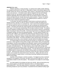
Graph 1.1. Dissolved Oxygen Control Strategy
Thermo Scientific
Single-Use Bioreactor (S.U.B.)
32
Section 1.9
S.U.B. Operating Instructions
Overlay Sparge Line
• Air
Open Pipe Sparge Line
Frit Sparge Line
• Air
•
•
•
•
Air
O2
CO2
N2
Figure 1.19 Recommended Gas Inflow Setup
In developing the gassing strategy for the dual sparge S.U.B. bag it is
recommended that a cascade system be used to maintain dO2 setpoint
starting with the open-pipe only (air ramping from 0 to 100% output),
then cascading to air to the frit (ramping from 0 to 100% output) when
needed, then finally O2 to the frit. This strategy has allowed excellent
CO2 stripping and high O2 delivery for high cell densities with little foam
formation. The cell culture medium used may vary these results (refer to
Graph 1.1 and Figure 1.19).
Thermo Scientific
Single-Use Bioreactor (S.U.B.)
33
Section 1.9
S.U.B. Operating Instructions
For more information on growth of specific cell lines in the S.U.B. system,
please contact technical support.
Media Fill
Agitation
1. Select desired line set from the S.U.B. BPC for fluid introduction.
2. Make aseptic connection (tubing welder, quick connect or tri-clamp)
and begin liquid fill.
3. Once approximately 20-30 L of volume has been added, verify the
position of the BPC in the outer support container, particularly the
sparger and the drain line. Adjust positioning if necessary for proper
fit.
4. It is recommended that the top corners of the BPC be pulled upward
to reduce wrinkles during filling. NOTE: The BPC must be pulled at
the top corners as the bag will generally form wrinkles during liquid
fill. If the film is not pulled from the top to remove wrinkles, film
tensioning below the bearing port will result.
5. The stretch hooks can be removed from bottom corners of the S.U.B.
BPC when fluid volume reaches 30% volume. This will eliminate any
interference with the load cell readings.
6. Fill to desired liquid volume — 50%-100% of rated volume is
recommended.
7. If employing a liquid batch-to-tank grounding cable with the
stainless steel connector of the sample line, the sample line should be
purged of air prior to probe calibration.
1. Once the media has reached half volume of the S.U.B., the agitation
control can be turned on via the motor ON/OFF switch.
2. Using the arrow keys, adjust the setpoint speed to the desired level
(the red LED display indicates the stirring speed in RPM). Adjust
desired agitation rate within the recommended range per Table 1.6.
3. Allow speed to stabilize, then make fine adjustments if necessary.
NOTE: Agitation must be stopped when volume falls below minimum
(1/2 of the rated volume), otherwise damage to the hardware or
disposable components may result. ▲
Temperature Control
(Electric Resistive
Heating Systems)
Thermo Scientific
1. After the agitation has been set, turn on the temperature controller via
the temperature controller keypad (left button). A flashing numeric
display indicates the controller is off (standby mode).
2. Adjust temperature set value using the up and down arrows located to
the right.
3. The process temperature value is shown in red.
Single-Use Bioreactor (S.U.B.)
34
Section 1.9
S.U.B. Operating Instructions
Temperature Control
(Water Jacket Systems)
1.
2.
3.
Drive Shaft Rotation
Connection to an external temperature control unit (TCU) is made
via the large quick connect couplings located on the vessel jacket.
Ensure the inlet/outlet ports are connected properly; improper
installation may result in poor heating/cooling performance.
Jacket should be purged of air any time the vessel jacket lines are
reconnected.
Temperature set points are controlled by the TCU. Refer to the
TCU manufacturer’s guidelines for setup and operating instructions.
Verify rotation of the drive shaft is operating in a counterclockwise motion
when viewed from the top looking down. The S.U.B. is designed to mix
in this direction only.
pH Probe Calibration
In general, the pH probe calibration (post-autoclave) can be verified by
pulling a sample and analyzing the pH on another calibrated pH meter.
DO Probe Calibration
After polarizing for 6 to 8 hours, the DO probe can be calibrated in the
S.U.B. using standard protocols. In general, turn on full air sparging (do
not exceed 1 lpm in 50 L, 1 lpm in 100 L, 2 lpm in 250 L, < 4 lpm in 500 L, <6 lpm in 1000 L, or <10 lpm in the 2000 L) until the DO reading
stabilizes; this is 100% DO setpoint for the controller. A zero percent
dissolved oxygen setpoint can be achieved by sparging with nitrogen or by
unplugging the DO probe momentarily.
Checkpoints Prior to
Inoculation
Verify the following before inoculation:
√ Once S.U.B. is filled with media, disconnect BPC tabs from the
S.U.B. hardware.
√ Verify temperature and agitation are at the desired setpoints.
√ pH probe is calibrated, autoclaved and connected via a Kleenpak
Connector port.
√ DO probe is autoclaved, connected via a Kleenpak Connector port,
polarized (6 to 8 hours) and calibrated.
√ Temperature RTD is completely seated in the thermo-well and
secured.
√ A method for making aseptic tubing connections should be available.
Thermo Scientific
Single-Use Bioreactor (S.U.B.)
35
Section 1.9
S.U.B. Operating Instructions
Cell Inoculation
Once the S.U.B. is operating at the targeted steady equilibrated state and
has achieved temperature, the S.U.B. is ready for inoculation. Connect
the inoculum addition line set to the seed culture vessel (equipped with
the proper connectors/tubing) and transfer the inoculum into the S.U.B.
Typically this is done with the tubing connection process (aseptic luer
lock connection or tube welding) and peristaltic pump. Pump the desired
volume of seed cells into the S.U.B. NOTE: For shear sensitive cultures,
cells can be introduced by manipulating the addition port to direct the
inoculum down the interior wall of the BPC and into the bulk fluid,
reducing the shear on the cells. Custom line sets can be supplied with
dip tubes which shorten the distance between the point of inoculum
introduction and the bulk fluid level.
Checkpoints In-Process
Verify the following once or twice daily during the culture run:
√ Visual verification of sparging (rising bubbles) through the sparge
access window.
√ Verification of process parameters such as temperature and agitation
are at setpoint.
√ Bag is not operating under pressure.
√ Cap is tight on drive shaft.
√ Temperature RTD is completely seated and secured.
√ That no condensate accumulates in exhaust filter housing. If
condensate has accumulated then this indicates that use of a filter
heater or a Condenser System is required.
NOTE: Noise may be emitted from the mixer assembly during operation.
This noise may vary in intensity and frequency, but generally has no
significant effect upon performance or overall durability of the S.U.B. BPC
during the intended life of the product. ▲
Dispense and Harvest
Thermo Scientific
1.
2.
3.
4.
Connect bottom drain tubing set to intended transfer line.
Open clamp positioned at the bottom drain port.
Begin drain by use of peristaltic pump.
When approximately 3-5 liters remain in the S.U.B. BPC, lift the
S.U.B. BPC at the top hanging tabs located opposite of the bottom
drain (this will pool media towards drain).
5. Hold bottom drain line near floor while lifting exhaust filter side of
S.U.B. BPC to facilitate the drain of the final liter of harvest media.
Single-Use Bioreactor (S.U.B.)
36
Section 1.9
S.U.B. Operating Instructions
S.U.B. BPC Disposal
Once the S.U.B. is drained, the drive shaft can be removed and stored
by reversing the steps used during assembly. The S.U.B. BPC can then
be removed from the outer support container. Filters can be removed
and integrity tested as needed as per user’s standard procedures. All
product contact materials related to the S.U.B. can be disposed of in an
appropriate waste container or incinerator. S.U.B. Shutdown
1. Once run is complete, verify motor agitation is off and turn off the
power to the outer support container by switching off the main
power disconnect.
2. If the S.U.B. hardware has come in contact with caustic materials
during the course of a run, rinse affected areas with a light water
rinse, followed by normal routine cleaning (see Preparation for Next
Run section).
3. Loose items such as the drive shaft, tools and RTD probes should be
returned to their storage locations to prevent accidental damage.
Preparation for
Next Run
Between runs, the S.U.B. hardware (outer support container, probe shelf,
drive shaft and mixer drive, etc.) can be wiped down with sanitary wipe.
The outer support container can also be cleaned with typical stainless steel
cleaner. Store drive shaft in storage holder located near the handle of the
outer support container.
The S.U.B. hardware system can be cleaned to the extent of standard
laboratory cleaning procedures. Care should be taken to ensure electrical
connections have been disconnected and electrical enclosures are closed
tightly. It is also recommended that excess water is not introduced under
the heat shield or over the control panel. A wipe down with normal
disinfectant solutions is sufficient, but without using excessive amounts of
liquid. The unit must be allowed to fully dry prior to being brought back
into operation.
Thermo Scientific
Single-Use Bioreactor (S.U.B.)
37
Section 1.9
S.U.B. Operating Instructions
Routine Maintenance
Preventive
Maintenance Schedule
Environmental conditions, operating parameters and the ability of the
user to adhere to standard operating procedures as outlined in this User’s
Guide can have significant impact upon the useful life of the S.U.B.
hardware system. The following guidelines are based upon standard
operating conditions as outlined in the S.U.B. User’s Guide.
High wear items such as bearings, seals, O-rings, and sterilization valves
common to conventional bioreactor systems have been purposefully
considered in the design of the disposable construction of the S.U.B.
The S.U.B. system is inherently robust and requires low levels of
routine maintenance. Taking time between bioreactor runs to clean the
exterior of the S.U.B. is certain to improve the appearance and overall
longevity of the hardware system. The drive motor is industrial grade
induction motor with permanently sealed and lubricated gear box.
The drive shaft is constructed to wear slightly with use and should be
visually inspected after each run. The heating elements are designed to
operate well within manufacturer’s design limits and will provide years
of consistent performance. Visual inspection of wear components and
following the guidelines listed below will be sufficient to ensure years of
dependable service. Replacement parts are available (refer to Section 4.4
for information).
Replace drive shaft assembly after one year of service or refer to the
following wear specifications:
•• Refer to the Table 1.7 for new drive hex diameters and minimum
drive shaft head hex diameters. Diameters are measured at widest
location across the points. Replace worn shaft head assembly when
drive hex diameter at widest location measures equal to or less across
the points (Figure 1.20).
•• Lightly coat drive cap threads with food-grade anti-seize if cap
becomes difficult to turn.
•• Replacement of the drive motor and heater element is recommended
after two years of service.
S.U.B. System
New Hex Diameter
Minimum Hex Diameter
50, 100 and 250 L
0.587”+/- 0.005” [14.9 mm]
0.566” [14.4 mm]
500 and 1000 L
0.839” +/- 0.005” [21.3 mm]
0.820” [20.8 mm]
2000 L
Replace after 1 year of service (mandatory).
Table 1.7 Shaft head dimensions
Hex diameter
measurement location
Figure 1.20 Shaft head assembly
Thermo Scientific
Single-Use Bioreactor (S.U.B.)
38
Section 2
Calibration Procedures
Section 2 Operating Information
This section covers the following:
2.1
Calibration Procedures
2.2
BPC Loading Instructions (50 L, 100 L, 250 L and 500 L)
2.3
BPC Loading Instructions (1000 L)
2.4
BPC Loading Instructions (2000 L)
2.5
Probe Assembly
2.6
Sampling
2.7
Pall Kleenpak Connector Instructions
2.1 Calibration
Procedures
Mixer Speed
Calibration
To verify the calibration of the mixer speed, use a calibrated tachometer.
Expect accuracy of +/- 1 rpm. Speed scaling can be modified if the
calibration needs to be adjusted. Please refer to Section 3.6 for details.
Temperature Controller
Calibration
To verify the calibration of the temperature controller/RTD, use a S.U.B.
silicone thermo-well, the existing 1/8” OD RTD and a user supplied
calibrated temperature bath.
Pressure monitor
Calibration
(when present)
To verify the calibration of the pressure monitor, use a calibrated pressure
standard. Pressures can be verified by clamping the BPC inlet line and
supplying gas through the overlay gas filter. Expect accuracy of +/- 0.1
psi. The monitor can be calibrated manually by referencing the monitor
operator’s manual supplied in the ETP.
Load Cell Calibration
(when present)
Thermo Scientific
Load cells arrive uncalibrated; it is recommended the load cell
manufacturer or a qualified technician calibrate these systems on site.
Refer to Appendix C for load cell calibration instructions. Expect accuracy
of +/- 0.5 kg. Basic load cell default parameters are listed in the electrical
schematic included with the ETP.
Single-Use Bioreactor (S.U.B.)
39
Section 2.2
Single-Use Bioreactor BPC Loading 50-500 L Volumes
2.2 Single-Use
Bioreactor BPC
Loading for
50 - 500 L Volumes
Thermo Scientific
Each outer support container is designed for a specific Single-Use
Bioreactor BPC. Confirm the correct volume BPC is being used for the
corresponding volume outer support container. The following section
outlines the installation and setup of the S.U.B. BPC.
1. Remove irradiated bioreactor BPC from protective double polybags
(Figure 2.1).
2. Load S.U.B. BPC from the top into the outer support container
(Figure 2.2).
3. Orient S.U.B. BPC with bearing port up and toward motor drive
with Kleenpak Connector probe ports facing bottom access cut-out
(Figure 2.3).
4. Place the bearing port into bearing port receiver, close door and close
clamp (Figure 2.4).
5. Route the side and bottom ports through the side access panel and
slot in tank bottom (Figure 2.5, Figure 2.6).
6. Direct the sparges, bottom drain and sampling lines through outer
support container access windows (Figure 2.7, Figure 2.8). NOTE:
The 500 L systems have a hatch covering the access window for the
bottom sparge..
Figure 2.1
Figure 2.2
Figure 2.3
Figure 2.4
Figure 2.5
Figure 2.6
Figure 2.7
Figure 2.8
Single-Use Bioreactor (S.U.B.)
40
Section 2.2
Single-Use Bioreactor BPC Loading 50-500 L Volumes
7. Connect incoming gas feed lines to both the overlay filter and the
direct sparge filter (Figure 2.9, Figure 2.10).
Figure 2.9
Figure 2.10
8. Inflate S.U.B. BPC with air (inflation time approximately 20 min)
through overlay filter, but do not exceed 25 lpm or 0.5 psi (0.34 bar)
internal BPC pressure. As BPC inflates, ensure it is properly oriented
in the support container (port alignment, drain, sparge, etc.). .
WARNING: DO NOT EXCEED 0.5 psi (0.034 bar) within the BPC or
BPC could fail. For reference the BPC will appear to be tight at 0.1 psi
(0.007 bar). ▲
9. As the bag begins to fill with air, manipulate the bag to align the
sparge lines in the base slot (Figure 2.11A, Figure 2.11B).
NOTE: While a sparge line check valve is provided for each sparge
line, it is not uncommon for some fluid to bypass check valves during
typical use. Elevating the filter to ensure that it is not at the low point
of the sparge line will reduce the chance that the filter is exposed to
liquid. ▲
.
.
.
.
.
.
.
.
.
.
.
.
Figure 2.11A Membrane Sparge
Positioning
Thermo Scientific
Figure 2.11B Aligning Dual
Sparge in Base Slot
Single-Use Bioreactor (S.U.B.)
41
Section 2.2
Single-Use Bioreactor BPC Loading 50-500 L Volumes
10.Use the four bottom cut-outs located at the base of the support
container as a reference to align hanging tabs on S.U.B. BPC
(Figure 2.12).
Figure 2.12
11. Attach platform stretch hooks to each of the four bottom corners of
the BPC (Figure 2.13).
Figure 2.13
12. Position bottom-side drain, pulling out/downward to position port
towards bottom edge of tank.
13. Align row of Kleenpak Connector probe ports within access window
(Figure 2.14).
Figure 2.14
NOTE: Verify all port clamps are closed and located as CLOSE as possible
to the body of the S.U.B. BPC. ▲
Thermo Scientific
Single-Use Bioreactor (S.U.B.)
42
Section 2.2
Single-Use Bioreactor BPC Loading 50-500 L Volumes
NOTE: Air fill of the S.U.B. BPC takes approximately 10-20 minutes
to allow for drive shaft insertion (times will vary based on flow rate, inlet
pressure and bag volume). The BPC must be at least partially inflated in
order to insert drive shaft. ▲
14. Remove the latch pin from the safety cover over the mixing assembly
and open the cover. Unscrew the threaded cap covering the hollow
pass-through of the motor (Figure 2.15).
Figure 2.15. Mixing Assembly
15. Split shaft assembly–500 L system only: Verify the two sections of
the drive shaft are located in the drive shaft holders near the side of
the outer support container. The sections will be referred to as upper
(section with the drive shaft head), and lower (section with the square
end). Lubricate the threaded ends with a light coat of food grade
anti-seize with each use.
•• Insert lower section of drive shaft through hollow pass-through
of mixing assembly (Figure 2.16).
•• Once inserted, slide latch pin from mixing assembly into shaft to
prevent it from falling into the tube (Figure 2.17).
•• Assemble the upper and lower sections of the drive shaft by
joining the segments and with a counterclockwise motion, hand
tighten the two sections together (Figure 2.18). Remove latch
pin.
•• Locate one wrench on the flat area in the lower drive shaft
section, another wrench on the upper section and tighten the
connection using a counterclockwise rotation (Figure 2.19). The
shafts are reverse threaded to avoid loosening during operation. CAUTION: Do not over tighten; a snug fit is sufficient.
Thermo Scientific
Single-Use Bioreactor (S.U.B.)
43
Section 2.2
Single-Use Bioreactor BPC Loading 50-500 L Volumes
••
Thermo Scientific
Once the sections are secure, return the wrenches to the tool
holder. .
Figure 2.16
Figure 2.17
Figure 2.18
Figure 2.19
Single-Use Bioreactor (S.U.B.)
44
Section 2.2
Single-Use Bioreactor BPC Loading 50-500 L Volumes
Drive Shaft Insertion
(50- 500L Volumes)
Thermo Scientific
16. Insert drive shaft through hollow pass-through of mixing assembly in
the following manner (Figures 2.20 - 2.23).
•• Use two hands to load drive shaft through top of mixing
assembly; a slight back and forth twisting motion will aid in
insertion and avoid stretching of the impeller tubing.
•• When approximately 2-3” (5.08 cm) of shaft remains, twist
slightly to engage impeller.
•• When approximately 1-2” (2.54 cm) of shaft remains, twist
slightly to engage bearing assembly.
•• When approximately 0.25” (0.64 cm) of shaft remains, twist
to align motor drive keyway with one of the four outer slots
on the drive shaft head..
.
.
.
.
.
.
.
.
.
.
.
.
Figure 2.20
Figure 2.21
Figure 2.22
Figure 2.23
Single-Use Bioreactor (S.U.B.)
45
Section 2.2
Single-Use Bioreactor BPC Loading 50-500 L Volumes
17. Directly couple drive shaft to motor drive (Figures 2.24 - 2.26).
•• Place threaded cap on hollow pass-through and hand tighten
clockwise.
•• Tighten cap by placing spanner wrench on hollow passthrough and tighten cap using supplied torque wrench.
NOTE: The torque wrench is a standard 3/8” square drive,
and it is calibrated at the factory at 150 in-lbs.
•• Verify wrenches have been removed from system and placed in
storage holders.
•• Close safety access cover and insert latch pin.
Figure 2.24
Figure 2.25
Figure 2.26
18. The air supply to the overlay can be turned off once the drive shaft
has been inserted.
Thermo Scientific
Single-Use Bioreactor (S.U.B.)
46
Section 2.2
Single-Use Bioreactor BPC Loading 50-500 L Volumes
Final Installation Steps
19. Optional: Wrap and secure vent filter heater on exhaust filter.
Connect heater to controller and verify it is plugged into an
appropriate 120 or 240 VAC outlet, then connect the power cord to
the controller. NOTE: Controller is preset to 50°C.
20. Secure exhaust vent filter on side-mounted holder (Figure 2.27A
and 2.27B). NOTE: 500 L S.U.B. bags and some custom S.U.B.
BPCs are supplied with dual exhaust vents. Extended single and
dual exhaust vent brackets are available (see section 4.3 for ordering
information).
Figure
2.27A
Figure 2.27B
21. Position and close a bar clamp (Part No. SV20664.01) on the bottom
drain line as close as possible to the BPC port (Figure 2.28).
Figure 2.28
Thermo Scientific
Single-Use Bioreactor (S.U.B.)
47
Section 2.2
Single-Use Bioreactor BPC Loading 50-500 L Volumes
22. Insert RTD or selected temperature sensor into thermo-well
(Figure 2.29, Figure 2.30). a. Place small amount of glycerol (0.5 mL) in well to aid in heat
transfer.
b. Sensor should be inserted until base of probe meets the mouth
of the thermo-well.
c. Secure by twisting the luer lock collar if provided. The thermowell will stretch slightly when RTD is seated.
Figure 2.29
Figure 2.30
23. Optional: Connect pressure transducer to user-supplied monitoring
device.
24. Continue to Section 2.5 for probe insertion instructions.
25. Close the bottom access hatch (500 L only). The proper latch tension
can be obtained by a combination of feel and visual inspection.
When closing the latch the handle should begin to provide resistance
to closing when the leading edge of the safety pin pass through of
the latch handle aligns with the outside edge of the latch base (Figure
2.31). NOTE: When the latch is under-tensioned the safety pin pass
through of the latch handle will be covered within the latch base and
the handle will close very easily. If the latch is over-tensioned the
handle will be excessively difficult to close.
26. The access doors must be closed and fully latched prior to filling the
system with liquid.
Outside Edge of Latch
Base
Safety Pin Pass Through
of Latch set
Latch Retainer
Safety Pin Pass Through
of Latch-Handle
Figure 2.31
Thermo Scientific
Single-Use Bioreactor (S.U.B.)
48
Section 2.3
Single-Use Bioreactor BPC Loading 1000 L Electric Resistive Heater
2.3 Single-Use
Bioreactor BPC
Loading for
1000 L Electric
Resistive Heater
Before beginning, verify that the outer support container is stationary
with casters locked into place. BPC loading may require operators to step
inside the bioreactor and the unit must be stationary for the safety of both
operator and equipment. For ease in BPC loading, two operators may be
required. For drive shaft insertion, a ladder or other means of elevation is
required.
1. Open both doors on bioreactor support container and reach inside to
open clamp on bearing port receiver located below the motor (Figure
2.32, Figure 2.33). If attached, remove the probe shelf from the front
of the tank cut-out and store on the platform..
Figure 2.32
.
.
.
.
.
.
.
.
.
.
.
.
.
.
.
.
Thermo Scientific
Figure 2.33
Single-Use Bioreactor (S.U.B.)
49
Section 2.3
Single-Use Bioreactor BPC Loading 1000 L Electric Resistive Heater
2. Remove irradiated S.U.B. BPC from protective double polybags
(Figure 2.34). Do not remove the polybags from the line sets at this
stage as the BPC may become difficult to manage. Do not allow the
BPC or line sets to touch or drag on the floor..
.
.
.
.
.
.
.
.
.
.
.
.
.
.
.
.
.
.
.
Figure 2.34
3. Reach into or step inside the outer support container with the front
face (bearing port side) of the BPC oriented towards the motor
(Figure 2.35)..
.
.
.
.
.
.
.
.
.
.
.
.
.
.
.
.
Figure 2.35
.
Thermo Scientific
Single-Use Bioreactor (S.U.B.)
50
Section 2.3
Single-Use Bioreactor BPC Loading 1000 L Electric Resistive Heater
4. Place the top line sets (still in polybags) on top of the cross supports
located on the top of the outer support container (Figure 2.36). This
will keep the BPC from being restricted during the air inflation step..
.
.
.
.
.
.
.
.
.
.
.
Figure 2.36
.
5. Load the BPC bearing port into the receiver (Figure 2.37) and close
the door and clamp (Figure 2.38)..
.
.
.
.
.
.
.
.
.
.
.
.
.
.
.
.
. Figure 2.38
Figure 2.37
.
.
.
.
.
.
.
.
.
Thermo Scientific
Single-Use Bioreactor (S.U.B.)
51
Section 2.3
Single-Use Bioreactor BPC Loading 1000 L Electric Resistive Heater
6. Remove the bubble wrap from the sparge filters. Guide the sparge
inlet lines and filters through the bottom cutouts in the outer support
container (Figure 2.39); the operator can reach just below the tank to
further extend the sparge lines from the cutouts (Figure 2.40)..
Figure 2.39
Figure 2.40
Pass the bagged drain line set and temperature/sampling port set through
the large cut-out in the front of the outer support container (Figure 2.41).
Extend the drain line set through the cut-out (Figure 2.42)..
.
.
Figure 2.41
Thermo Scientific
Figure 2.42
Single-Use Bioreactor (S.U.B.)
52
Section 2.3
Single-Use Bioreactor BPC Loading 1000 L Electric Resistive Heater
Gas Supply
Connections and Air
Inflation
The BPC should be partially inflated to allow for proper insertion of the
drive shaft and to aid in proper alignment of the BPC in the outer support
container.
8. Connect pressure transducer to monitor and once the display has
stabilized, tare the monitor (the monitor should be allowed to warm
up for 30 minutes before taring). Verify that the monitor reads zero.
9. Attach air supply to overlay gas inlet line. .
NOTE: Air pressure to the overlay gas line on the S.U.B. BPC should not
exceed 3 psi (less than 25 lpm). ▲ .
WARNING: DO NOT EXCEED 0.5 psi (0.34 bar) within the BPC or
the system could fail causing personal injury or damage to equipment.
DO NOT leave the BPC unattended while inflating. ▲
10. Begin air inflation through the overlay gas line.
11. While the BPC is inflating, attach the incoming gas supply to the
sparger gas inlet line.
.
NOTE: Air pressure to the sparger on the S.U.B. BPC should not exceed
8 psi. Also, while a sparge line check valve is provided for each sparge line,
it is not uncommon for some fluid to bypass check valves during typical
use. Elevating the filter to ensure that it is not at the low point of the
sparge line will reduce the chance that the filter is exposed to liquid. ▲
12. Tare the load cell display before proceeding.
13. Using the four stretch hooks provided, secure the BPC by attaching
the hooks to the hanging tabs on the bottom of the BPC (Figure
2.43, Figure 2.44). Verify that the sparge filter and sparge remain in
position while attaching the stretch hooks. It is recommended that
users secure the hanging tabs on the front BPC panel first. This way
the door will not be an obstruction when connecting the last set of
stretch hooks.
Figure 2.43
Thermo Scientific
Figure 2.44
Single-Use Bioreactor (S.U.B.)
53
Section 2.3
Single-Use Bioreactor BPC Loading 1000 L Electric Resistive Heater
14. While BPC begins to fill with air, remove the protective packaging
from the exhaust vent filters (Figure 2.45).
Figure 2.45
15. Air fill of the S.U.B. BPC takes approximately 15-20 minutes before
drive shaft insertion can begin (times will vary based upon flow rate
and inlet pressure) (Figure 2.46).
Figure 2.46
Thermo Scientific
Single-Use Bioreactor (S.U.B.)
54
Section 2.3
Single-Use Bioreactor BPC Loading 1000 L Electric Resistive Heater
Four hanging tab hooks are located on the top of the outer support
container. These hooks can be used to secure the BPC from the top
hanging tabs once it is inflated.
Drive Shaft Insertion
The drive shaft is constructed in three or four pieces which must be
assembled and inserted piecewise. Reminder: Operators should be elevated
(i.e. ladder) to effectively assemble and insert the drive shaft.
16. Prepare the hollow pass-through by first removing the latch pin on
the safety cover (Figure 2.47), opening the safety cover (Figure 2.48)
and removing the threaded cap (turn counterclockwise) of the mixing
assembly (Figures 2.49 and 2.50).
Figure 2.47
Figure 2.48
Cap
Hollow
Pass-Through
Drive Shaft Head
Motor Drive Keyway
Latch Pin
Figure 2.49
Safety Cover
Motor
Drive Shaft
Figure 2.50. Mixing Assembly
Thermo Scientific
Single-Use Bioreactor (S.U.B.)
55
Section 2.3
Single-Use Bioreactor BPC Loading 1000 L Electric Resistive Heater
17. Verify the three sections of the drive shaft are located in the drive
shaft holders on the side of the outer support container. The sections
will be referred to as the upper (section with the drive shaft head),
middle (section with internal/external threads on each end) and lower
(section with the square end). Lubricate the threaded ends with a
light coat of food grade anti-seize with each use.
18. First insert the lower section through the hollow pass-through of
the mixer drive (Figure 2.51). Slide latch pin from mixing assembly
into shaft to prevent it from falling into the tube. Assemble the
middle and lower sections of the drive shaft by joining the segments
with a twisting motion, fasten the two sections together (Figure
2.52). NOTE: Segmented shaft threads are left handed. Locate one
wrench on the flat area in the middle drive shaft section, another
wrench on the lower section and tighten the connection using
a counterclockwise rotation (Figure 2.53). The shafts are reverse
threaded to avoid loosening during operation. Once the sections are
secure, return the wrenches to the tool holder. CAUTION: Do not
over tighten; a snug fit is sufficient. Remove the latch pin.
Figure 2.51
Figure 2.52
Figure 2.53
Thermo Scientific
Single-Use Bioreactor (S.U.B.)
56
Section 2.3
Single-Use Bioreactor BPC Loading 1000 L Electric Resistive Heater
Load the partially assembled drive shaft through the hollow pass-through
and hold it in position sufficient to allow a wrench to be placed on the
upper most flats of this shaft section. Obtain the upper section of the
drive shaft and assemble it to the other segment in the manner described
previously (Figure 2.54, Figure 2.55).
Figure 2.54
Figure 2.55
19. Using two hands, carefully guide the completed drive shaft into the
BPC using a slight back and forth twisting motion (Figure 2.56).
NOTE: It may be necessary for another operator to assist with drive
shaft insertion. As one operator inserts the drive shaft, another
operator should carefully manipulate the impeller when the end of
the drive shaft begins to couple with the impeller.
a. When 2-3” (5.08 cm) of shaft remains, twist slightly to engage
the impeller.
b. When 1-2” (2.54 cm) of shaft remains, twist slightly to engage bearing assembly.
c. When 0.25-.50” (0.64 cm) of shaft remains, twist to align motor
drive keyway with one of the four outer slots on the drive shaft
head.
Figure 2.56
Thermo Scientific
Single-Use Bioreactor (S.U.B.)
57
Section 2.3
Single-Use Bioreactor BPC Loading 1000 L Electric Resistive Heater
20. Directly couple the drive shaft to the motor by placing the threaded
cap back on the hollow pass-through and tighten.
21. Tighten cap by placing spanner wrench counterclockwise on hollow
pass-through and tighten using supplied torque wrench (Figure 2.57).
NOTE: The torque wrench is a standard 3/8” square drive and it is
calibrated at the factory at 150 in-lbs.
Figure 2.57
22. Verify wrenches have been removed from the system and returned to
the storage holders.
23. Close safety access cover and insert latch pin.
Securing Access Doors
(Resistive Heater Only)
The procedures listed below must be followed in full detail and in proper
order to ensure the S.U.B. outer support container is operated in a safe
manner. The outer support container is subjected to high structural loads
due to the weight and pressure of the fluid and gas contained in the
BPC. In order to ensure structural integrity of the system it is necessary
for the tension on each door be even and involves a two step tensioning
procedure of the latches. Neglecting these instructions may result in
personal injury and/or permanent damage to hardware system. The access
doors of the outer support container should never be opened when the
BPC is filled with liquid.
24. Close both the left and right side access doors of the outer support
container while paying close attention to ensure the BPC is not
pinched in any of the door seams.
Thermo Scientific
Single-Use Bioreactor (S.U.B.)
58
Section 2.3
Single-Use Bioreactor BPC Loading 1000 L Electric Resistive Heater
25. Each door is supplied with four side latches; the closure sequence and
tension method must be performed in the following manner (Figure
2.58). Following this sequence will ensure that the outer support
container will retain the proper shape and structure after repeated
use.
1
Third
2
First
3
4
Second
Fourth
Figure 2.58. Latch Closure Sequences (latch references are shown in circles)
26. The doors should be secured first with the two middle latches (latches
2 and 3). Proper tension is obtained by adjusting the threaded latch
pin. Tension of the latch is adjusted by varying the position of the pin
on the threaded shank (Figure 2.59).
.
Figure 2.59
Thermo Scientific
Single-Use Bioreactor (S.U.B.)
59
Section 2.3
Single-Use Bioreactor BPC Loading 1000 L Electric Resistive Heater
27. The proper latch tension can be obtained by a combination of feel
and visual inspection. When closing the latch the handle should
begin to provide resistance to closing when the leading edge of the
safety pin pass through of the latch handle aligns with the outside
edge of the latch base (Figure 2.60). NOTE: When the latch is
under-tensioned the safety pin pass through of the latch handle will
be covered within the latch base and the handle will close very easily.
If the latch is over-tensioned the handle will be excessively difficult to
close.
Outside Edge of
Latch Base
Safety Pin Pass
Through of Latch Base
Latch Retainer
Safety Pin Pass
Through of Latch
Handle
Figure 2.60
28. Once the two middle latches are closed, the top (latch 1) and bottom
latches (latch 4) can be closed using the same tensioning procedures.
29. Both the left and right access doors must be closed and fully latched
prior to proceeding to the final latch tensioning procedures. The final
procedure that follows must be performed one latch at a time.
30. Release latch 2 (notice that tension on the latch is less than seen when
the latch was first closed) and adjust the threaded latch pin sufficient
to allow the latch handle to begin to tension.
31. Release latch 3 and adjust the tension as in the previous step.
32. Release latch 1 and adjust the tension and close.
33. Release latch 4 and adjust the tension and close.
34. For maximum security insert safety pins (not included) into the
respective latches.
35. Once the drive shaft is inserted and side access doors closed, turn off
the air supply to the overlay line. If the optional exhaust vent filter
heaters are being used, secure heaters to the filter at this time.
Thermo Scientific
Single-Use Bioreactor (S.U.B.)
60
Section 2.3
Single-Use Bioreactor BPC Loading 1000 L Electric Resistive Heater
Final Installation Steps
Secure exhaust vent filters on top-mounted holders by use of the filter
side vents (Figure 2.61A) or if using elevated dual exhaust filters, use the
adapter piece and extended filter bracket (Figure 2.61B).
Figure 2.61A
Figure 2.61B Extended Dual
Filter Bracket
37. Fully extend the drain line set through the front cutout and attach
the probe shelf.
38. Remove the poly bag from the drain line set and position the line
clamp as close as possible to the BPC port and close. Use a cable tie
around the clamp to ensure the clamp cannot be accidentally opened.
39. Align the five Kleenpak ports through the front access window .
(Figure 2.62).
Figure 2.62
Thermo Scientific
Single-Use Bioreactor (S.U.B.)
61
Section 2.3
Single-Use Bioreactor BPC Loading 1000 L Electric Resistive Heater
40. Insert RTD or selected temperature sensor into the thermo-well
(Figure 2.63).
a. Place a small amount of glycerol (0.5 mL) in well to aid in
heat transfer.
b. Sensor should be inserted until base of RTD meets the mouth
of the thermo-well.
c. Secure by twisting the luer lock collar if provided the .
thermo-well will stretch slightly when RTD is seated (Figure
2.64).
Figure 2.63
Figure 2.64
NOTE: Verify all port clamps are closed and located as near as possible to
the body of the S.U.B. BPC. ▲
Thermo Scientific
Single-Use Bioreactor (S.U.B.)
62
Section 2.3
Single-Use Bioreactor BPC Loading 1000 L Water Jacket
Loading 1000 L
Water Jacket
1. Open both the upper and lower doors on outer support container
and reach inside to open clamp on bearing port receiver located
below the motor (Figure 2.65). If attached, remove the probe shelf
from the front of the tank cut-out and store on the platform.
2. Remove irradiated S.U.B. BPC from protective double polybags. Do
not remove the polybags from the line sets at this stage as the BPC
may become difficult to manage. Do not allow the BPC or line sets
to touch or drag on the floor.
3. Load the BPC through the top access door; orient the bottom of the
BPC first with the bearing port facing upward (Figure 2.66)..
.
.
.
.
.
.
.
.
.
.
.
. Figure 2.66
Figure 2.65
4. Place the top line sets (still in polybags) over the side of the outer
support container. This will help support the weight of the BPC and
also keep the BPC from being restricted during the air inflation step.
5. Load the BPC bearing port into the receiver (Figure 2.67) and close
the door and clamp (Figure 2.68).
Figure 2.67
Thermo Scientific
Figure 2.68
Single-Use Bioreactor (S.U.B.)
63
Section 2.3
Single-Use Bioreactor BPC Loading 1000 L Water Jacket
6. Connect pressure transducer to monitor. Once the display has
stabilized, tare the monitor (the monitor should be allowed to warm
up for 30 minutes before taring). Verify that the monitor reads zero.
Gas Supply
Connections and
Air Inflation
The BPC should be partially inflated in order to aid in proper alignment
of the BPC in the outer support container and will be necessary to allow
for proper insertion of the drive shaft.
7. Attach air supply to overlay gas inlet line at the top of the BPC.
NOTE: Air pressure to the overlay gas line on the S.U.B. BPC should not
exceed 3 psi (less than 25 lpm). ▲ WARNING: DO NOT EXCEED 0.5 psi (0.34 bar) within the BPC or
the system could fail, causing personal injury or damage to equipment.
DO NOT leave the BPC unattended while inflating. ▲
NOTE: Air pressure to the sparger on the S.U.B. BPC should not exceed
8 psi. Also, while a sparge line check valve is provided for each sparge line,
it is not uncommon for some fluid to bypass check valves during typical
use. Elevating the filter to ensure that it is not at the low point of the
sparge line will reduce the chance that the filter is exposed to liquid. ▲
8. Remove the bubble wrap from the bottom sparge filter. Use the
lower door to gain access to floor of the hardware, guide the sparge
inlet line and filter through the bottom cutout in the outer support
container (Figure 2.69). Two holes are present in the tank; the hole
furthest from tank centerline should be utilized with standard S.U.B.
BPC having a single sparge port (a supplied cover plate is typically
used to cover the second hole when using a standard BPC). The
operator can reach just below the tank to further extend the sparge
line from the cut-out (Figure 2.70).
Figure 2.69
Thermo Scientific
Figure 2.70
Single-Use Bioreactor (S.U.B.)
64
Section 2.3
Single-Use Bioreactor BPC Loading 1000 L Water Jacket
9. By use of the access door, pass the bagged drain line set and
temperature/sampling port set through the large cutout in the front
of the outer support container (Figure 2.71). Extend the drain line
set through the cutout.
Figure 2.71
10. Tare the load cell display before proceeding.
11. Using the four stretch hooks provided, secure the BPC by attaching
the hooks to the hanging tabs on the bottom of the BPC (Figure
2.72). Verify that the sparge filter and sparge remain in position while
attaching the stretch hooks. It is recommended that users secure the
hanging tabs on the front BPC panel first. This way the door will
allow access when connecting the last set of stretch hooks.
Figure 2.72
Thermo Scientific
Single-Use Bioreactor (S.U.B.)
65
Section 2.3
Single-Use Bioreactor BPC Loading 1000 L Water Jacket
12. While BPC begins to fill with air, remove the protective packaging
from the exhaust vent filters. If the bag is filled sufficiently with air
the filters can be loaded into the holder (Figure 2.73A). If using
elevated exhaust vent filters, use the corresponding extended dual
vent filter bracket (Figure 2.73B).
13. Four hanging tab hooks are located on the top of the outer support
container. These hooks can be used to secure the BPC from the top
hanging tabs once it is inflated. If connecting all four corners requires
excessive stretching of the BPC it is acceptable to only use two or
more hooks (preferably at opposite corners)(Figure 2.74).
Figure 2.73A
Figure 2.73B
Figure 2.74
Thermo Scientific
Single-Use Bioreactor (S.U.B.)
66
Section 2.3
Single-Use Bioreactor BPC Loading 1000 L Water Jacket
Drive Shaft Insertion
The drive shaft is constructed by assembling three or four pieces; these
must be assembled and inserted piecewise in areas having low ceilings.
Reminder: Operators should be elevated (i.e. ladder) to effectively
assemble and insert the drive shaft.
14. Verify the drive shaft sections and tools are available.
15. Prepare the hollow pass-through by first removing the latch pin on
the safety cover (Figure 2.75), opening the safety cover and removing
the threaded cap [turn counterclockwise] (Figure 2.76) of the mixing
assembly (Figures 2.77).
Figure 2.75
Cap
Hollow
Pass-Through
Figure 2.76
Drive Shaft Head
Motor Drive Keyway
Safety Cover
Latch Pin
Motor
Drive Shaft
Figure 2.77 Mixing Assembly
Thermo Scientific
Single-Use Bioreactor (S.U.B.)
67
Section 2.3
Single-Use Bioreactor BPC Loading 1000 L Water Jacket
16. Verify the three sections of the drive shaft are located in the drive
shaft holders on the side of the outer support container. The sections
will be referred to as the upper (section with the drive shaft head),
middle (section with internal/external threads on each end) and lower
(section with the square end). Lubricate the threaded ends with a
light coat of food grade anti-seize with each use.
17. First insert the lower section through the hollow pass-through of
the mixer drive (Figure 2.78). Once inserted, slide latch pin from
mixing assembly into shaft to prevent it from falling into the tube
(Figure 2.79). Assemble the middle and lower sections of the drive
shaft by joining the segments and with a twisting motion, fasten the
two sections together (Figure 2.80). NOTE: Segmented shaft threads
are left handed. Locate one wrench on the flat area in the middle
drive shaft section, another wrench on the lower section, and tighten
the connection using a counterclockwise rotation (Figure 2.81).
The shafts are reverse threaded to avoid loosening during operation.
CAUTION: Do not over tighten; a snug fit is sufficient. Remove the
latch pin.
Figure 2.78
Figure 2.79
Figure 2.80
Figure 2.81
Remove the latch pin, load the partially assembled drive shaft through the
hollow pass-through and hold it in position sufficient to allow the latch
pin to be inserting in to the next set of holes and allow the wrench to
Thermo Scientific
Single-Use Bioreactor (S.U.B.)
68
Section 2.3
Single-Use Bioreactor BPC Loading 1000 L Water Jacket
be placed on the upper most flats of this shaft section. Obtain the upper
section of the drive shaft and assemble it to the other segment in the
manner described previously (Figure 2.82, Figure 2.83). Once the sections
are secure remove the latch pin and return to the wrenches to the tool
holder.
Figure 2.82
Figure 2.83
19.Using two hands, carefully guide the completed drive shaft into the
BPC using a slight back and forth twisting motion or a counterclockwise rotation.
• When 2-3” (5.08 cm) of shaft remains, twist slightly to engage
the impeller.
• When 1-2” (2.54 cm) of shaft remains, twist slightly to engage bearing assembly (Figure 2.84).
• When ~0.25” (0.64 cm) of shaft remains, twist to align motor
drive keyway with one of the four outer slots on the drive shaft
head.
20. Ensure the head is fully seated before directly coupling the drive shaft
to the motor by placing the threaded cap back on the hollow passthrough and tightening it. .
NOTE: The cap should be easy to install when the drive shaft head is
fully engaged in the hollow pass-through. Otherwise repeat all steps
of #19 before installing cap.
Figure 2.84
Thermo Scientific
Single-Use Bioreactor (S.U.B.)
69
Section 2.3
Single-Use Bioreactor BPC Loading 1000 L Water Jacket
21. Directly couple the drive shaft to the motor by placing the threaded
cap back on the hollow pass-through and tighten.
22. Tighten cap by placing spanner wrench (counterclockwise) on hollow
pass-through and tighten using supplied torque wrench (Figure 2.85).
NOTE: The torque wrench is a standard 3/8” square drive and it is
calibrated at the factory at 150 in-lbs.
Figure 2.85
Securing Access Doors
23. Verify wrenches have been removed from the system and returned to
the storage holders.
24. Close safety access cover and insert latch pin.
25. The access doors should be secured first with the latches. Proper
tension is obtained by adjusting the threaded latch pin. Tension
of the latch is adjusted by varying the position of the pin on the
threaded shank.
26. The proper latch tension can be obtained by a combination of feel
and visual inspection. When closing the latch the handle should
begin to provide resistance to closing when the leading edge of the
safety pin pass through of the latch handle aligns with the outside
edge of the latch base. (Figure 2.86) NOTE: When the latch is
under-tensioned the safety pin pass through of the latch handle will
be covered within the latch base and the handle will close very easily.
If the latch is over-tensioned the handle will be excessively difficult to
close.
.
. Outside Edge of Latch
. Base
.
. Safety Pin Pass Through
of Latch set
.
. Latch Retainer
Safety Pin Pass Through
of Latch-Handle
Figure 2.86
Thermo Scientific
Single-Use Bioreactor (S.U.B.)
70
Section 2.3
Single-Use Bioreactor BPC Loading 1000 L Water Jacket
Final Installation Steps
27. For maximum security insert safety pins (not included) into the
respective latches.
28. Once the drive shaft is inserted and side access doors closed, turn off
the air supply to the overlay line. If the optional exhaust vent filter
heaters are being used, secure heaters to the filter at this time.
29. Verify position of the exhaust vent filters on top-mounted holders by
use of the velcro fasteners (Figure 2.87).
Figure 2.87
30. Fully extend the drain line set through the front cutout and attach
the probe shelf.
31. Remove the poly bag from the drain line set and position the line
clamp as close as possible to the BPC port and close. Use a cable tie
around the clamp to ensure the clamp cannot be accidentally opened.
32. Align the five Kleenpak ports through the front access window .
(Figure 2.88). This will be the lower cutout if hardware is supplied
with two horizontal slots.
Figure 2.88
Thermo Scientific
Single-Use Bioreactor (S.U.B.)
71
Section 2.3
Single-Use Bioreactor BPC Loading 1000 L Water Jacket
33. Insert RTD or selected temperature sensor into the thermo-well
(Figure 2.89).
a. Place a small amount of glycerol (0.5 mL) in well to aid in
heat transfer (Glycerol - Sigma G6279).
b. Sensor should be inserted until base of RTD meets the mouth
of the thermo-well.
c. Secure by twisting the luer lock collar if provided. The thermowell will stretch slightly when RTD is seated (Figure 2.90).
Figure 2.89
Figure 2.90
NOTE: Verify all port clamps are closed and located as near as possible to
the body of the S.U.B. BPC. ▲
Thermo Scientific
Single-Use Bioreactor (S.U.B.)
72
Section 2.4
Single-Use Bioreactor BPC Loading 2000 L Water Jacket
2.4 Loading 2000 L
Water Jacket
1. Main power to the control panel should be switched on. Ensure
that the drive motor is not running. Open both the front and rear
doors on outer support container and use an elevated platform to
open clamp on bearing port receiver located below the motor (Figure
2.91). Lower the hoist lifting frame to a position just above the top of
the rear door by using the pneumatic control lever near the rear door. .
2. Two operators should carefully remove irradiated S.U.B. BPC from
protective double polybags. Do not remove the polybags from the
line sets at this stage as the BPC may become difficult to manage. Do
not allow the BPC or line sets to touch or drag on the floor. .
Figure 2.91
3. Load the BPC through the rear access door; orient the bottom of the
BPC into the door first with the bearing port facing upward (Figure
2.92). Keep the BPC folded as supplied in the packaging, it will allow
the bag to unfold naturally when lifted by the hoist..
.
.
.
.
.
.
.
.
.
.
.
.
.
Figure 2.92
.
4. Using the rear door for access, connect the retainer hooks of the
hoist to the top of the BPC via the hanging tabs starting with the
furthermost two tabs (Figure 2.93) and finishing with the closer two
tabs (Figure 2.94)..
5. Raise the BPC using the pneumatic lift, one operator observing from
above with the second operator at ground level controlling the lifting
valve (Figure 2.95). .
6. Raise the hoist until the lift reaches full stroke. Once lifting stops
the top level operator should hold the hoist frame and apply some
minimal lifting force. This will assist the lifting device to pull in any
remaining slack in the cable and ensure the lift device has been fully
raised. Place the valve in the stop position.
Thermo Scientific
Single-Use Bioreactor (S.U.B.)
73
Section 2.4
Single-Use Bioreactor BPC Loading 2000 L Water Jacket
Figure 2.93
Figure 2.94
Figure 2.95
7. Place the top line sets (still in polybags) onto the lifting frame or
over the side of the outer support container. This will help support
the weight of the BPC and also keep the BPC from being restricted
during the air inflation step..
Figure 2.96
8. Remove the black protective cap from the bearing port (Figure 2.96),
load the BPC bearing port into the receiver (Figure 2.97) and close
the bearing assembly door and clamp (Figure 2.98)..
.
.
.
.
.
.
.
.
.
.
.
.
.
.
Figure 2.97
Figure 2.98
.
9. Open the tubing set polybag and connect pressure transducer to
monitor. Once the display has stabilized, tare the monitor (the
monitor should be allowed to warm up for 30 minutes and the sensor
connected for 10 minutes before taring). Verify that the monitor
Thermo Scientific
Single-Use Bioreactor (S.U.B.)
74
Section 2.4
Single-Use Bioreactor BPC Loading 2000 L Water Jacket
Gas Supply
Connections and Air
Inflation
reads zero.
The BPC must be partially inflated in order to aid in proper alignment
of the BPC in the outer support container and is necessary to allow for
proper insertion of the drive shaft..
10.Attach air supply to overlay gas inlet line at the top of the BPC.
Operators should allow the bag to fill to greater than half volume
(typically > 20 minutes)..
.
NOTE: Air pressure to the overlay gas line on the S.U.B. BPC should
not exceed 5 psi (less than 100 lpm). ▲
.
WARNING: DO NOT EXCEED 0.5 psi (0.34 bar) within the
BPC or the system could fail, causing personal injury or damage to
equipment. DO NOT leave the BPC unattended while inflating. ▲
11.Feed the probe belt, sample line, and the subsurface addition lines
through the front access door (Figure 2.99).
Figure 2.97
12.Remove sparge lines from the poly bags and bubble wrap from sparge
filters. Use the rear door to gain inside access to the floor of the
hardware. Place a clamp on the bottom drain line at this time (Figure
2.100)..
.
.
.
.
.
.
.
.
.
.
.
.
.
Figure 2.98
.
13.Guide the sparge inlet line and filter through the bottom cutout in
the outer support container.
• The plastic center tank insert of the floor provides the port
locations for both the bottom drain (Figure 2.101) and the open
pipe sparge (Figure 2.102).
• Opening the pivoting access cover in the bottom of the tank will
allow access for loading the frit sparge gas line (Figure 2.103).
Thermo Scientific
Single-Use Bioreactor (S.U.B.)
75
Section 2.4
Single-Use Bioreactor BPC Loading 2000 L Water Jacket
Figure 2.101
Figure 2.102
Figure 2.103
Figure 2.104
Three cut-out holes are provided in the tank for frit sparges; these holes are
furthest from tank center line and align with the inside edge of this access
cover door (Figure 2.104).
NOTE: Air pressure to the sparger on the S.U.B. BPC should not exceed
8 psi. Also, while a sparge line check valve is provided for each sparge line,
it is not uncommon for some fluid to bypass check valves during typical
use. We recommend elevating the sparge line filter as is feasible to help
reduce this tendency. ▲
14.Tare the load cell display before proceeding..
15.Using the positioning tab pins provided, secure the BPC by attaching
the tabs on the bottom of the BPC onto the position tab pins (Figure
2.105, 2.106). Verify that the sparge filter and sparges remain in
position while attaching the tabs. It is recommended that users secure
the tabs on the front BPC panel first. This way the larger rear door will
allow access when connecting the last set of tab pins.
Thermo Scientific
Single-Use Bioreactor (S.U.B.)
76
Section 2.4
Single-Use Bioreactor BPC Loading 2000 L Water Jacket
Figure 2.105
Figure 2.106
16.While the BPC begins to fill with air, remove the protective
packaging from the exhaust (vent) filters. If the bag is filled
sufficiently with air the filters can be loaded into the holder.
• If using the exhaust condenser system, follow the setup
instructions in Section 2.4.
• If using elevated exhaust vent filters, use the corresponding
extended dual vent filter bracket and filter heaters. Follow the
setup instructions in Section 2.4.
Thermo Scientific
Single-Use Bioreactor (S.U.B.)
77
Section 2.4
Single-Use Bioreactor BPC Loading 2000 L Water Jacket
Disposable Exhaust
Condenser
Condenser System
Functional Overview
The condenser system is intended to be used as an accessory to the
Single-Use Bioreactor (S.U.B.) as an alternative to vent filter heaters. The
condenser’s purpose is to prevent liquids and solids from condensing and
collecting inside of the vent filters of the S.U.B. The condenser system
cools the exhaust gasses leaving the S.U.B. chamber, condensing the
moisture out of the saturated gasses coming from the S.U.B. The liquid
condensate that is stripped from the exhaust gasses is then pumped
back into the S.U.B. chamber, creating a sterile loop and significantly
reducing liquid loss due to evaporation. The condenser plate is chilled
by a closed bath recirculating chiller which has sufficient capacity to cool
two condenser plates simultaneously. Figure 2.107 shows a functional
diagram of the condenser system.
Exhaust Line
From S.U.B.
Filter Straps
Filter Bracket
Assembly
Condenser Post
Assembly
Exhaust Vent
Filters
Condenser Plate
Assembly
Condenser Return
Line Back to S.U.B.
Post Receivers
Dual Headed
Peristaltic Pump
Condenser Bag
Gas Outlet Port
Dual Chamber
Condenser Bag
Condenser Bag
Liquid Drain Ports
Condenser Bag
Gas Inlet Port
Closed Bath
Recirculating
Gripping
Chiller
Tabs
Cart
Assembly
Alignment Holes
Condenser Disposables
Condenser Hardware
Condenser System
Figure 2.107. Condenser System Overview
Thermo Scientific
Single-Use Bioreactor (S.U.B.)
78
Section 2.4
Single-Use Bioreactor BPC Loading 2000 L Water Jacket
Guidance for when
to use the Condenser
System
2000 L S.U.B.–BPC with
Single-Use Condenser
System
Large 10” hydrophobic PVDF filters with a nominal 0.2 micron pore
size were specified in order to increase the available surface area for offgassing. In conjunction, the standard 2000 L S.U.B. is designed for use
with a single use condenser system. This allows the S.U.B. to utilize a
powerful phase-change type system which provides improved exhaust
vent protection and reliability due to the ability to strip condensate and
atomized materials that may be present from the off-gas stream of the
S.U.B. This system has been shown to significantly reduce the “fouling”
load on the vent filters that inherently increases operating back pressure
as the cell culture run batch progresses. See Single-Use Bioreactor
Validation Guide for specific details.
2000 L S.U.B.–BPC with
Vent and Heaters Only
Some end-users may prefer to omit the Condenser System on the 2000
L S.U.B. under the expectation that this will allow for a more uniform
installation (similar to smaller S.U.B.s used in the upstream seed train),
or will perhaps reduce system complexity and cost. The use of exhaust
vent heaters and 10” filters will provide some impressive flow capacity
over short periods (<5-days). However, the high sparge rates required
during the scale-up of the S.U.B. to the 2000 L working volume may
eventually create conditions of increased operating back pressure,
usually due in part to blocking of the filter media. Depending upon the
application, the user has the option of using both filters in parallel or
initiating the run with a single filter, temporarily clamping off the line to
the other filter (it being reserved as redundant back-up).
NOTE: The disposable Condenser System has the potential to provide
continuous and nearly indefinite protection against performance
degradation of the exhaust vent filters (rated for continuous flow rates .
up to a total off-gassing rate of 50 lpm and intermittent flows up to .
100 lpm). See Single-Use Bioreactor System Validation Guide.
Thermo Scientific
Single-Use Bioreactor (S.U.B.)
79
Section 2.4
Single-Use Bioreactor BPC Loading 2000 L Water Jacket
Table 2.1 can help end-users specify the BPC configuration and
operating parameter setup for custom 2000 L S.U.B. applications when
not utilizing the disposable exhaust condenser. Because the operating
parameters of different cell cultures vary widely, a safety factor should
be used to temper the data. As such, the data we used to generate a
control base line are for reference only (filter fouling will vary and must
be considered to ensure reliable performance). It is assumed no foam is
present in the exhaust stream.
S.U.B. System
(2 ea 10” vents)
Run Duration
2000 L S.U.B.
2000 L S.U.B.
2000 L S.U.B.
2000 L S.U.B.
7 days
10 days
14 days
21 days
Max. Combined Flow
Rate Recommended
Resulting Safety
Factor
40 lpm
2X
32 lpm
2.5X
27 lpm
3X
Strongly Recommend: Single Use Condenser
Table 2.1. Condenser System Overview
The above recommendations were generated using the test conditions
shown in Graph 2.1. In this case a 2000 L S.U.B. was filled with 2000
L of DI water with a batch temperature of 40°C using a MKS vent
filter heater at 60°C. Safety factor estimates are based on a maximum
continuous internal S.U.B. BPC pressure not to exceed 0.1 psi (which
corresponds to 40 lpm with a single 10” vent).
2000 L S.U.B. BPC - Pressure Trending
Direct Sparge Gas Loading, 2000 L DI Water @ 40°C, Vent Heater @ 60°C
0.25
Overlay Pressure (psi)
0.20
0.15
0.10
0.05
0
10
20
30
40
50
60
70
80
90
Air Sparge (lpm)
Single Meissner 10” Vent (0.2 micron PVDF)
Graph 2.1
NOTE: These results do not take into consideration a “fouling” safety
factor. ▲
Thermo Scientific
Single-Use Bioreactor (S.U.B.)
80
Section 2.4
Single-Use Bioreactor BPC Loading 2000 L Water Jacket
Also consider the size and type of tubing used to connect the exhaust
vents to the S.U.B. BPC (when not using an exhaust condenser).
Braid reinforced tubing provides the best protection against kinking or
accidental pinching of the exhaust line. The 10” vents are supplied with
¾” hose barbs and this tubing diameter will allow condensate to return to
the S.U.B. at total off-gas flow rates up to 30 lpm (assuming the tubing is
near a vertical orientation). Testing has shown that large diameter tubing
will allow for lower exhaust gas velocities and if the vapor velocity is
below 0.6 m/s, gravity will allow the condensate formed in the tubing to
return to the batch process.
NOTE: Restrictive tubing connectors can create flow bottle necks and
½” ID tubing is typically deemed too small for the 2000 L S.U.B.. ▲
Tubing I.D. Recommendation (inches)
Flow Rate (lpm) Versus Vapor Exit Velocity (m/s) - 0.61 m/s Velocity Threshold
Gas Vapor Velocity (m/s)
2.5
2.0
1.5
1.0
0.5
0
0
10
20
30
40
60
50
70
80
90
100
Flow (lpm)
0.63
0.75
1.00
Threshold
Graph 2.2
Thermo Scientific
Single-Use Bioreactor (S.U.B.)
81
Section 2.4
Single-Use Bioreactor BPC Loading 2000 L Water Jacket
Various vent filter configurations are available on the S.U.B. depending
upon the process scale and intended application. Graph 2.2 provides
a reference for determining the relative capacity of different filters
depending upon the amount of gas flow anticipated and the length of
the run. In all cases, using a vent filter heater will reduce the chance of
condensate blocking the filter but over time suspended solids carried
in the exhaust stream will impede the flow of exhaust gas (resulting in
increased back pressure). In addition, it is good practice to monitor the
amount of foam present in the head space. In all cases, a vent filter heater
have very little tolerance for handling the presence of foam in the exhaust
stream. A small feed of antifoam (e.g., 10% simethicone, SH30897.02)
added directly to the liquid surface of the culture head space typically
provides excellent foam control. Large systems (especially the 1000
and 2000 L S.U.B.) can benefit from the use of a disposable condenser
system. It has been shown to increase system reliability at high flow
rates (beyond 50 lpm) and should warrant strong consideration when
performing batch runs beyond 10 days. Results will vary; however, it is
strongly recommended that end users select a vent filter configuration
providing reserve capacity where possible. For example, dual vent
configurations can be used independently with the second filter serving
as a redundant backup (providing a quick reserve in case issues arise in
process).
Off-Gassing Management Guidelines for Single Use Bioreactor
Condenser System vs. Exhaust Vent Heaters
(Conditions: 37°C batch temperature, no foam in exhaust stream)
100
Total Off-Gassing Load (LPM)
90
80
70
60
50
40
30
20
10
0
0
7
14
21
28
35
42
49
56
Run Duration (days)
Condenser System (2 X 10" vents)
Vent Heater System (2 X 3" vents)
Vent Heater System (2 X 10" vents)
Vent Heater System (1 X 3" vents)
Graph 2.2
Thermo Scientific
Single-Use Bioreactor (S.U.B.)
82
Section 2.4
Single-Use Bioreactor BPC Loading 2000 L Water Jacket
Condenser System
Functional Overview
(cont.)
Two operators are required to safely setup the disposable exhaust system.
Setup time is typically 2-3 min..
1. The first operator, located at the elevated position, should remove
the condenser BPC carefully from the poly-bag packaging and then
lower the assembly (directed in a vents first orientation) to the second
operator located at ground level, standing to the rear but between the
condenser cart and the S.U.B. (Figure 2.108)..
2. The first operator at the upper position moves to ground level, opens
both doors on the chiller plate, and loads the condenser BPC from
the front, keeping the BPC in a saddle bag shape. The vents can hang
freely (Figure 2.109). .
Figure 2.108
3. The second operator routes the gas inlet lines around and behind the
vent holders and inspects both lines to ensure they are connected to
the S.U.B. and are not twisted or kinked, adjusting them as needed
(Figure 2.110)..
.
.
.
.
.
.
.
.
.
.
.
.
.
Figure
Figure 2.110
. 2.109
.
4. The second operator then holds the vent filters, places them into the
vent filter holders above the chill plate (Figure 2.111). .
5. The first operator then uses the Velcro staps to secure the filters in
position (Figure 2.112)..
6. The first operator then uses the grasping tabs to position the bag
using the two lower button pins on each side of the chiller plate
(Figure 2.113). .
Thermo Scientific
Single-Use Bioreactor (S.U.B.)
83
Section 2.4
Single-Use Bioreactor BPC Loading 2000 L Water Jacket
Figure 2.111
Figure 2.112
Figure 2.113
7. The clear side doors are then closed as the operator carefully
manipulates first the gas inlet line and then the gas outlet line (Figure
2.114) to clear the doors as each is closed and latched (Figure 2.115)..
8. The second operator then locates the gas inlet lines into the clips
behind the vents (Figure 2.116)..
.
Figure 2.114
Thermo Scientific
Figure 2.115
Figure 2.116
Single-Use Bioreactor (S.U.B.)
84
Section 2.4
Single-Use Bioreactor BPC Loading 2000 L Water Jacket
9. The first operator loads the peristaltic tubing into the pump, verifying
there is sufficient slack at each end of the pump tubing, aligns tubing
in the pump channel closes the pump ramp (Figure 2.117)..
10.The pump is then started (pushing the red button, Figure 2.118).
Operators verify that both the pump and chiller are enabled and
running at the proper settings (we recommend that the pump setting
be 12-30 RPM and the chiller 5°C). Specified pumping system is
qualified to run continuously (wet or dry) beyond 21 days.
Figure 2.117
Figure 2.118
11.After setup the operators should verify the following:
• The elbow fittings on the inlet and outlet of the condenser saddle
bag are straight and level
• The gas inlet line and the condensate line are not twisted,
pinched, or obstructed.
• Low spots in the gas inlet line should be avoided. Adjust the lines
to avoid condensation pooling
• The pump union is loose on both ends of the pump and running
smoothly in the peristaltic rollers..
Specific performance questions can be answered by reviewing the
Disposable Condenser portion of the S.U.B. Validation Guide or
contacting technical support.
Thermo Scientific
Single-Use Bioreactor (S.U.B.)
85
Section 2.4
Single-Use Bioreactor BPC Loading 2000 L Water Jacket
Exhaust Vent Heater
(optional)
1. A single operator can safely set up the exhaust vents and heaters in
this configuration..
2. Clip each filter one at a time into the elevated vent filter holder
system; carefully center the filter housing allowing the clip to secure it
near the hose barb connections (Figure 2.119). .
3. Verify the routing of the exhaust tubing, ensuring that it is not likely
to cause kinks in the tubing..
4. Place the vent heaters around each filter ensuring the snap retainers
are secured. Position the power leads to avoid interfering with the
vent holder brackets (Figure 2.120)..
5. Raise and rotate the vent holder bracket as needed. Make final
inspection to ensure no kinks or low spots will occur in the
tubing between the BPC and the filter (even if the BPC becomes
pressurized) (Figure 2.121)..
6. Connect the power to the vent heaters and verify operation of controllers..
7. Inspect the controllers’ set points (recommended 60˚ C). After 2-5
minutes of operation, verify the vent heaters are warm and near the
desired temperature set points and that no alarm indicators are active.
Figure 2.119
Thermo Scientific
Figure 2.120
Figure 2.121
Single-Use Bioreactor (S.U.B.)
86
Drive Shaft Insertion
1. The drive shaft is constructed by assembling four pieces; these must
be assembled and inserted piecewise in areas having low ceilings. .
2. Reminder: The BPC must be filled with enough air to allow for
unrestricted loading of the angled drive shaft. Operators should be
elevated (i.e. ladder) to effectively assemble and insert the drive shaft..
3. Verify the drive shaft sections and tools are available. .
4. Prepare the hollow pass-through by first removing the latch pin
on the safety cover (Figure 2.122), opening the safety cover, and
removing the threaded cap [turn counterclockwise] (Figure 2.123) of
the mixing assembly (Figures 2.124).
Figure 2.122
Cap
Hollow
Pass-Through
Figure 2.123
Drive Shaft Head
Motor Drive Keyway
Safety Cover
Latch Pin
Motor
Drive Shaft
Figure 2.124 Mixing Assembly
Thermo Scientific
Single-Use Bioreactor (S.U.B.)
87
Section 2.4
Single-Use Bioreactor BPC Loading 2000 L Water Jacket
Verify the four sections of the drive shaft are located in the drive shaft
holders on the side of the outer support container. The sections will
be referred to as the upper (section with the drive shaft head), middle
– 2 each (section with internal/external quick connect on each end),
and lower (section with the square end). .
.
NOTE: No lubrication is required with the quick connect assembly
design. ▲
5. First insert the lower section through the hollow pass-through of
the mixer drive (Figure 2.125). Once inserted, slide latch pin from
mixing assembly into shaft to prevent it from falling into the impeller
sleeve (tube), (Figure 2.126). .
Figure 2.125
Figure 2.126
6. To connect two shafts together, the button on the female side is
depressed (Figure 2.127) and the sleeve is slid back, this will expose
a red ring underneath the sleeve (Figure 2.128). This is a visual
indicator that the sleeve is not in a locked position..
Figure 2.127
Thermo Scientific
Figure 2.128
Single-Use Bioreactor (S.U.B.)
88
Section 2.4
Single-Use Bioreactor BPC Loading 2000 L Water Jacket
7. Place the female side of the quick connect over the male end (Figure
2.129). The connection is fully seated when the red of the male end is
no longer exposed (Figure 2.130). .
8. Slide the sleeve towards the connection, allowing the push button to
lock into position, this will engage the locking mechanism and also
cover the red indicator ring (Figure 2.131).
.
NOTE: Once fully connected, no red coloring should be visible. This
state of no visible red indicates a proper connection. ▲
Figure 2.129
Figure 2.130
Figure 2.131
9. Remove the latch pin, load the partially assembled drive shaft
through the hollow pass-through and hold it in position sufficient to
allow the latch pin to be inserted in to the next set of holes. .
10.Assemble the two middle sections of the drive shaft by joining the
segment using the quick connects as performed in the previous steps..
11.Obtain the upper section of the drive shaft and assemble it to the
other segment in the manner described previously. Once the sections
are secure, remove the latch pin and return the wrenches to the tool
holder.
Thermo Scientific
Single-Use Bioreactor (S.U.B.)
89
Section 2.4
Single-Use Bioreactor BPC Loading 2000 L Water Jacket
12.Using two hands, carefully guide the completed drive shaft into the
BPC using a slight back and forth twisting motion or a counterclockwise rotation (Figure 2.132).
• When 2-3” (5.08 cm) of shaft remains, twist slightly to engage
the impeller.
• When 1-2” (2.54 cm) of shaft remains, twist slightly to engage bearing assembly (Figure 2.133).
• When ~0.25” (0.64 cm) of shaft remains, twist to align motor
drive keyway with one of the four outer slots on the drive shaft
head (Figure 2.134)..
13.Ensure the head is fully seated before directly coupling the drive shaft
to the motor by placing the threaded cap back on the hollow passthrough and tightening it. .
.
NOTE: The cap should be easy to install when the drive shaft head is
fully engaged in the hollow pass-through. Otherwise repeat all steps
of # 13 before installing cap. ▲
Figure 2.132
Figure 2.133
Figure 2.13
14.Secure cap by placing spanner wrench on hollow pass-through and
tightening using the supplied torque wrench (Figure 2.135). .
.
NOTE: The torque wrench is a standard 3/8” square drive and it is
calibrated at the factory at 150 in-lbs. ▲
15.Verify wrenches have been removed from the system and returned to
the storage holders..
16.Close safety access cover and insert latch pin.
Figure 2.135
Thermo Scientific
Single-Use Bioreactor (S.U.B.)
90
Section 2.4
Single-Use Bioreactor BPC Loading 2000 L Water Jacket
Securing Access Doors
1. The access doors should be secured first with the latches. Proper
tension is obtained by adjusting the threaded latch pin. Tension
of the latch is adjusted by varying the position of the pin on the
threaded shank. .
2. The proper latch tension can be obtained by a combination of feel
and visual inspection. When closing the latch the handle should
begin to provide resistance to closing when the leading edge of the
safety pin pass through of the latch handle aligns with the outside
edge of the latch base. (Figure 2.136) .
.
NOTE: When the latch is under-tensioned the safety pin pass
through of the latch handle will be covered within the latch base and
the handle will close very easily. If the latch is over-tensioned the
handle will be excessively difficult to close. ▲
3. For maximum security insert pins (not included) into the respective
latches..
4. Turn off the air supply to the overlay line. Insert drive shaft and close
side access doors.
Outside Edge of Latch
Base
Safety Pin Pass Through
of Latch set
Latch Retainer
Safety Pin Pass Through
of Latch-Handle
Figure 2.136
Final BPC Installation
Steps
1. Verify the proper position of the exhaust filters and that the exhaust
flow path is unobstructed. Connect the gas supply lines - verify the
intended flow paths for overlay, frit sparges, and open pipe sparge..
2. Verify the overlay and direct sparge lines are well positioned and free
of kinks or unintended clamps. Verify the rear access door is closed
with proper latch tension..
3. Remove the poly bag from the drain line set and verify redundant
line clamps are in position. Use a cable tie around the clamp to
ensure the clamp cannot be accidentally opened.
Thermo Scientific
Single-Use Bioreactor (S.U.B.)
91
Section 2.4
Single-Use Bioreactor BPC Loading 2000 L Water Jacket
4. Ensure the front access door is latched and align the five Kleenpak
ports through the front access window (Figure 2.137). This will be
the lower cutout if hardware is supplied with two horizontal slots.
Position clamps as close as possible to the bag and close them on all
tube ports (Figure 2.138).
5. Place clamps on subsurface lines as close to the port as possible, this
will eliminate media from filling these lines prior to use (Figure 2.139).
Figure 2.137
Figure 2.138
Figure 2.139
6. Insert RTD or selected temperature sensor into the thermo-well
(Figure 2.140).
• Place a small amount of glycerol (0.5 mL) in well to aid in heat
transfer (Glycerol - Sigma G6279).
• Sensor should be inserted until base of RTD meets the mouth of
the thermo-well.
• Secure by twisting the luer lock collar if provided. The thermowell will stretch slightly when RTD is seated (Figure 2.140)..
Connect batch-to-tank grounding cable to the stainless steel
connector of the sample line (Figure 2.141).
.
NOTE: Verify all port clamps are closed and located as close as
possible to the body of the S.U.B. BPC. ▲
7. Important: During media fill verify the position of all critical
ports (drain, spargers, line sets, and probes) before more than
50 L of liquid is filled into the BPC. This will still allow time for
adjustments if it is required after the fill is initiated.
8. Typically two each fill lines (½” x ¾”) and peristaltic pumps are
recommended to fill the 2000 L S.U.B. in a timely manner.
Thermo Scientific
Single-Use Bioreactor (S.U.B.)
92
Section 2.4
Single-Use Bioreactor BPC Loading 2000 L Water Jacket
Figure 2.140
Probe Insertion
(2000 L)
Figure 2.141
1. Probe clips for the 2000 L S.U.B. do not require a probe tray. They
clip onto the outer support container and hang from above the probe
assembly (Figure 2.142)..
2. The probe clip attaches to the tank and is retained using an adjustable
ball detent (Figure 2.142). .
3. Install presterilized sensor and probe kit using aseptic connection
methods as described in Section 2.7. .
4. The aseptic connection is completed prior to the bellows being
collapsed (Figure 2.143)..
Figure 2.142
Thermo Scientific
Figure 2.143
Single-Use Bioreactor (S.U.B.)
93
Section 2.4
Single-Use Bioreactor BPC Loading 2000 L Water Jacket
Insert the probe by collapsing the bellows (Figure 2.144). .
.
NOTE: If the BPC is already filled with liquid the best practice is to
squeeze the bellows to expel air prior to collapsing it. Now insert the
probe fully as described previously. ▲
5. Position the probe clip in the desired horizontal location .
(Figure 2.145). The clip’s adjustable ball detent (spring loaded screw)
should be adjusted so the probe clip can be easily moved to the
desired position while still securing the clip to the steel support piece.
Figure 2.144
Figure 2.145
6. Swing the probe upward into the flexible spring clip (Figure 2.146).
Release the probe assembly and verify the probe remains at the proper
insertion depth and angle as the bellows expands to rest freely in the
probe clip (Figure 2.147).
Figure 2.146
Figure 2.147
NOTE: The fixed position of the probe clip and the flexible nature of the
spring retainer allow for both proper angle (>10 degrees) and compression
of the probe bellows. ▲
Thermo Scientific
Single-Use Bioreactor (S.U.B.)
94
Section 2.5
Probe Assembly
2.5 Probe Assembly
Preparation and
Sterilization
1. Select the appropriate probe (see Section 1). Verify the presence of
a Teflon support ring and O-ring on the probe and visually inspect
them for damage.
2. Perform any required probe maintenance and calibrate the pH probe
(see Probe Calibration within this section).
3. Insert the probe into the probe assembly through the threaded
adaptor.
4. Verify the probe tip is not touching (>1/4” [6.35 mm] gap) the
membrane of the Kleenpak Connector before threading into probe
adaptor.
5. Hand tighten the adaptor and verify the probe tip is not touching the
membrane.
6. Place the probe assembly with probe into the autoclave tray for probe
kits (Figure 2.148).
7. Autoclave the probe assembly using a validated sterilization cycle
(approximately 30 minutes at 122°C). Thirty minute sterilization
cycles are generally sufficient. Options of wet or dry cycle parameters
can be used. Slow exhaust cycles are preferred as this minimizes
stress on the probes during the temperature and pressure changes of
autoclaving.
8. Allow sufficient time for probe assemblies to cool completely before
seeking to connect to the S.U.B. bag for probe insertion.
9. When stored properly, the autoclaved probe assemblies can be
stored dry for short periods of time (< 24 hr) without loss of sensor
longevity, performance or sterility.
NOTE: Before beginning probe insertion, please become familiar with the
Kleenpak Connector procedure outlined in Section 2.7. ▲
Probe Assembly
Autoclave Tray for
Probe Kits
Figure 2.148
Thermo Scientific
Single-Use Bioreactor (S.U.B.)
95
Section 2.5
Probe Assembly
Probe Insertion
(50 - 1000 L)
1. Insert probes into S.U.B. BPC using autoclaved probe assemblies.
a. Place tubing clamps on all probe ports prior to attempting to
connect probe assemblies (this will prevent sterility loss in case
errors are made during connection of Kleenpak Connectors)
(Figure 2.149)..
.
.
.
.
.
.
.
.
Figure 2.149
b. Position probe support plate onto outer support container.
This holds the probes at a 15 degree incline for best
performance (Figure 2.150)..
.
.
.
.
.
.
.
.
Figure 2.150
c. Connect Kleenpak Connector using protocol outlined by the
manufacturer (Section 2.7).
d. Ensure all four snaps click on each connector and the base and
barrel of Kleenpak is fully seated.
e. Remove tubing clamp on the individual probe port.
f. Insert probe by collapsing bellows toward S.U.B. .
(Figure 2.151)..
.
.
.
.
.
.
.
.
Figure 2.151
g. Probe is seated when bellow is fully collapsed. A small amount
of fluid may enter the bellow if the probe is loaded after media
fill.
Thermo Scientific
Single-Use Bioreactor (S.U.B.)
96
Section 2.5
Probe Assembly
2. Secure probe by placing connected probe assembly first into probe
holder (Figure 2.152) and then locking the holder into probe support
shelf.
a. Begin by placing the entire collapsed probe assembly in the
probe holder starting with the Kleenpak Connector side being
placed in the holder side with the short fingers.
b. If necessary, compress the probe bellows further to allow the
probe assembly to be positioned and locked into the other end
of the probe holder (Figure 2.153).
c. Allow probe bellows to relax. This secures the probe between
the probe holder fingers.
d. Align probe holder with alignment holes of the probe support
shelf.
e. Press downward and into the slots closest to the S.U.B. BPC,
then slide the holder backward slightly to lock the probe
holder into the probe support shelf.
Kleenpak side
Probe cap side
Figure 2.152
Figure 2.153
NOTE: Probe ports that are not used prior to media fill must remain
clamped. Probe ports not used at the initiation of the run can be accessed
later for probe replacement or redundancy purposes if required. ▲
Probe Calibration
Thermo Scientific
Probe calibration is controller specific; however, the following general rules
apply:
a. pH probes must be calibrated prior to steam sterilization and the
calibration of the probe can be standardized by comparison of an offline sample once the pH probe has been connected to the S.U.B.
b. Dissolved oxygen probes are generally calibrated post steam
sterilization. Once the probe is connected to the S.U.B. and
is allowed sufficient time to polarize (6-8 hours of continuous
connection to the power supply provided by a controller or
polarization module), it can be calibrated.
Single-Use Bioreactor (S.U.B.)
97
Section 2.6
Single-Use Bioreactor BPC Sampling
2.6 Single-Use
Bioreactor BPC
Sampling
Sampling
During operation of the S.U.B., samples may need to be taken for
monitoring of various parameters established by the user. The following
describes two techniques for sampling: aseptic sampling via sterile syringe
and sampling utilizing a sterile manifold.
Aseptic Sampling
Using standard luer lock on 60 mL syringe or sterile manifold:
1. Remove dust cover from SmartSite (Figure 2.154)
2. Clean SmartSite with sanitary wipe
3. Connect sanitary luer lock type syringe (Figure 2.155)
4. Apply small amount of vacuum pressure by pulling out syringe
plunger slightly
5. Open pinch clamp and pull sample (approximately 30-60 mL) using
care not to allow any back flow
6. Close pinch clamp and remove syringe (this will be a purge sample)
7. Clean SmartSite with sanitary wipe
8. Connect sanitary luer lock type syringe
9. Apply small amount of vacuum pressure by use of syringe
10. Open pinch clamp and pull desired sample volume (approximately
10-20 mL) using care not to allow any back flow
11. Close pinch clamp and remove syringe (this will be a representative
sample)
12. Clean SmartSite with sanitary wipe and replace dust cap
Figure 2.154
Thermo Scientific
Figure 2.155
Single-Use Bioreactor (S.U.B.)
98
Section 2.6
Single-Use Bioreactor BPC Sampling
Sampling with
Sterile Manifold
Figures 2.156 and 2.157:
1. Remove manifold from protective poly-bag package
2. Close all clamps on manifold lines
3. Use sterile tubing welder to connect manifold to sample line
4. Inspect welds and open flow path by pinching the welds
5. Open two clamps at inlet and the clamp at purge bag (100 mL pillow
bag)
6. Purge sample line by filling this bag (recommended 30-60 mL)
7. Close clamp nearest purge bag
8. Open clamp to sample bag (50 mL pillow bag)
9. Allow bag to fill with liquid by gravity (recommended 10-20 mL)
10. Close clamps at sample manifold inlet
11. Close clamp nearest the sample bag
12. Remove the filled manifold from S.U.B. by welding new manifold
onto sample line (this will be used for taking the next sample)
Figure 2.156
Thermo Scientific
Figure 2.157
Single-Use Bioreactor (S.U.B.)
99
Section 2.7
Pall Kleenpak Connector Instructions
2.7 Pall Kleenpak
Connector
Instructions
These instructions and the information contained within must be read
thoroughly as they contain valuable information gained by extensive
experience. It is very important that all instructions are carefully followed
and where appropriate they should be incorporated into the end user’s
standard operating procedures. If some of the procedures do not suit your
needs, please consult Pall or your local distributor before using Kleenpak
connectors. Use of this product in a manner other than in accordance with
Pall’s current recommendations may lead to injury or loss. Pall cannot
accept liability for such injury or loss..
Installation and Operation
Training on the proper assembly and recommended uses of the Kleenpak
connector is necessary.
• Before installation, it is essential to verify that the Kleenpak
connector selected is suitable for the fluid to be processed and has
been sterilized appropriately.
• Complete assembly procedures and technical specifications for
Kleenpak connectors are contained in Pall publication USD 2233d.
• Please follow carefully the instruction below.
Pall Kleenpak
Connector
(Standard Instructions)
a. Lift and pull tab of protective caps to remove caps from connectors.
Step (a)
Thermo Scientific
Single-Use Bioreactor (S.U.B.)
100
Section 2.7
Pall Kleenpak Connector Instructions
b. Hold the barrel of the larger (male) connector above the base. Align
the smaller (female) connector with the larger (male) connector so
that both folded white peel away strips are facing the same direction
as they exit out the flat sides of the connectors.
Step (b)
NOTE: Rounded sides must be in alignment and the white peel away
strip must remain folded. If the connectors are not aligned properly, the
connection cannot be made. The peel away strips must remain folded. ▲
c. Once aligned correctly, press the two connectors together firmly until
both sets of locking clips snap together tightly.
Step (c)
d. While holding the Kleenpak Connector securely in hand, pull the
anti-actuation ring outward.
Step (d)
Thermo Scientific
Single-Use Bioreactor (S.U.B.)
101
Section 2.7
Pall Kleenpak Connector Instructions
e. With one hand, hold the barrel of the male connector. Using the
other hand, grasp both white peel away strips as close as possible
to the flat side of connector to ensure a good grip and pull them
out simultaneously in a smooth continuous motion. Ensure that
the connector is perpendicular to the peel away strips shown in
illustration for Step (e). The perpendicular orientation must be
maintained while the two strips are pulled simultaneously. Do not
use if only one white peel away strip is removed accidentally instead
of two; this will affect the sterility of the pathway.
Step (e)
NOTE: Do not impart radial force on the connector. A radial force
can cause the connector to break. If a radial force is present due to
items attached to the connector, then the connector must be properly
supported. ▲
f.
Rotate the thumb rest on the male connector one full turn at least
90 degrees in the clockwise direction. The rotation serves to bend
the anti-actuation tabs, which prevents inadvertent engagement. If
required, the thumb rest can be turned counterclockwise to remove
kinks in the tubing.
Step (f)
Step (g)
Thermo Scientific
Single-Use Bioreactor (S.U.B.)
102
Section 2.7
Pall Kleenpak Connector Instructions
g. Push the thumb rest of the male connector down towards the base
of the barrel until they meet. If the thumb rest has not already been
turned counterclockwise to remove tubing kinks, the thumb rest can
be turned counterclockwise while it is being pushed towards the base
of the barrel. .
.
NOTE: In order to establish a proper connection the plunger inside
the male connector must be fully inserted into the female connector.
As a verification, this normally occurs when the last or second to
last rings on the plunger locks into the ratchet. Minimally, the
second to last ring must be locked into the ratchet to ensure a proper
connection. The thumb rest can be turned one full turn back to
re-align tubing, as required, if the second to last ring is locked into
ratchet. If the plunger has been pushed further than the second to last
ring, then it may not be possible to turn the thumb rest. ▲
Step (h)
h. Start the fluid transfer.
Thermo Scientific
Single-Use Bioreactor (S.U.B.)
103
Section 2.7
Pall Kleenpak Connector Instructions
Pall Kleenpak
Connector
(Instructions for use
with assembly aid)
Receipt of the Equipment
The connector assembly aid is provided non sterile and can be reused
multiple times. It needs to be stored in clean and dry conditions between
each use.
Connect both halves of Kleenpak connector together
a. Lift and pull tab of protective caps to remove caps from connectors.
Step 3.1(a)
P rotective caps
Step (a)
b. Hold the barrel of the larger (male) connector above base.
• Align the smaller (female) connector with the larger (male)
connector.
• Flat sides should be aligned.
• Both peel away strips must remain folded and oriented in the
same direction.
Step
Step(b)
3.1(b)
Rounded side
Female
Connector
F lat side
where both folded
over peel a way
stri ps e xit
Anti-actuation
ring
Barrel
Male Connector
NOTE: If the connectors are not aligned properly, the connection cannot
be made. ▲
c. Once aligned correctly, press the two connectors together firmly until
both sets of locking clips snap together tightly.
Step
Step(c)
3.1(c)
Locking clips
(not visible)
Locking clips
WARNING: A KLEENPAK CONNECTOR WILL NOT FIT INTO
THE ASSEMBLY AID IF THIS CONNECTION IS NOT PROPERLY
SECURED. ▲
Thermo Scientific
Single-Use Bioreactor (S.U.B.)
104
Section 2.7
Pall Kleenpak Connector Instructions
Remove Anti-Actuation Device
d. While holding the Kleenpak Connector securely in hand, pull the
anti-actuation ring outward.
R emove the anti-actuation ring
from the male connector
Step(d)
3.2(a)
Step
Install into Assembly Aid
e. Place connected Kleenpak Connector unit firmly into assembly aid
so that both membrane strips protrude through the opening and are
easily accessible for removal.
Step
Step(e)
3.3
WARNING: KLEENPAK CONNECTOR SHOULD STAY
SECURELY IN THE ASSEMBLY AID WHEN PROPERLY
INSTALLED. ▲
Remove Membrane Strips
f. Hold assembly aid in the palm of hand with Kleenpak Connector
exposed outward, and thumb is supporting the Kleenpak Connector in
the unit. Using the other hand, firmly grasp both white peel away strips
as close as possible to the body of the assembly aid to ensure a secure
grip and pull them out simultaneously in a smooth continuous motion.
Ensure that the connector is perpendicular to the peel away strips.
Step (f)3.4
Step
Step(f)3.4
Step
WARNING: DO NOT USE IF ONLY ONE WHITE PEEL AWAY
STRIP IS REMOVED ACCIDENTALLY INSTEAD OF TWO; THIS
WILL AFFECT THE STERILITY OF THE PATHWAY. ▲
Thermo Scientific
Single-Use Bioreactor (S.U.B.)
105
Section 2.7
Pall Kleenpak Connector Instructions
Complete Flow Path Actuation
g. With Kleenpak Connector still secured in the assembly aid, rotate
and push the thumb rest of the male connector down towards the
base of the barrel until they meet. .
.
NOTE: In order to establish a proper connection, the plunger inside
the male connector must be fully inserted into the female connector.
▲
Step
3.5(a)
Step (g)
h. The thumb rest can be turned one full turn back to re-align tubing, as
required.
Step
Step(h)
3.5(b)
WARNING: VERIFY THAT THE PLUNGER HAS BEEN FULLY
INSERTED INTO OPPOSING CONNECTION BY USING
THE ASSEMBLY AID EDGE AS A GAUGE UPON COMPLETE
ACTUATION. ▲
Process
l. The Kleenpak Connector assembly is now complete and assembly aid
may be removed.
Thermo Scientific
Single-Use Bioreactor (S.U.B.)
106
Section 3
Specifications
Section 3 Specifications
This section covers the following information:
3.1
50 L S.U.B. Data Sheet and Specifications
3.2
100 L S.U.B. Data Sheet and Specifications
3.3
250 L S.U.B. Data Sheet and Specifications
3.4
500 L S.U.B. Data Sheet and Specifications
3.5
1000 L S.U.B. Data Sheet and Specifications
3.6
2000 L S.U.B. Data Sheet and Specifications
3.7
Condenser System Data Sheet and Specifications
3.8
Vent Filter Heater Data Sheet and Specifications
3.9
Load Cells Data Sheet and Specifications
3.10
Standard BioProcess Containers with Disk Sparge Systems Data Sheet
3.11 Recalibration of the AC-Tech.
Variable Speed Drive (SCF/SCM Models)
3.12
Troubleshooting
3.1 50 L Single-Use
Bioreactor
Thermo Scientific
3.1.1
3.1.2
3.1.3
3.1.4
50 L S.U.B. Data Sheet
50 L Technical Specifications - Electric Resistive Heater
50 L Technical Specifications - Water Jacket
50 L Control Panel Layout
Single-Use Bioreactor (S.U.B.)
107
Overview:
The HyClone® S.U.B. provides all the advantages of single-use
bioprocessing without having to buy a complete new bioreactor
system. The critical design parameters of the S.U.B., such as height to
diameter ratios, mixer design and location and typical control system
interfaces, have been maintained.
The S.U.B. BioProcess Container™ (BPC®) is supplied sterilized
by irradiation and therefore does not require any facility hook-ups for
sterilization or cleaning. A key element to the single-use design is the
plastic (polyethylene) impeller with a bearing/seal assembly linked to
an external mixer drive.
This document covers S.U.B. systems with
a maximum working volume of 50 L and the
new optimized standard S.U.B.s with dual
sparge capability which provide a wider range
of kLa values, better pH control and lower
foaming than the original disk sparger.
The S.U.B. system consists of the
following components:
1. Outer Support Container—with a mixer
drive complete with control unit and an
electrical heater or water jacket.
2. Single-Use Bioreactor BPC—complete
Item
Data Sheet 026 Rev 10
Thermo Scientific
HyClone Single-Use
Bioreactor (S.U.B.) 50 L
The Thermo Scientific HyClone
Single-Use Bioreactor (S.U.B.) is
the leading single-use alternative
to conventional stirred tank
bioreactors for animal and insect
cell culture. The current range
includes units with maximum
working volumes of 50, 100, 250,
500, 1000 and 2000 L. The S.U.B.
is now available with new
optimized standard BioProcess
Containers with improved dual
sparge capability. Open pipe and
frit sparging systems are now
included to provide a wider range
of operating conditions.
with agitator assembly, sparger, vent
filter inlet and outlet ports, plus ports for
integration of sensor probes and line sets.
The S.U.B. BPC is supplied sterile and
ready-to-use.
3. Drive Shaft—inserted into the S.U.B. BPC
through the mixing drive motor and locked
into the disposable agitator assembly.
4. Process Controls—temperature (not on
water jacket) and agitation control are
integrated into the S.U.B., but additional
pH or dissolved oxygen (DO) controls must
be supplied by the user.
50 L Electric
Resistive Heater
Rated Liquid Working Volume
50 L
Minimum Liquid Working Volume
25 L
Total Reactor Volume (Liquid & Gas)
BPC Chamber Diameter
BPC Chamber Shoulder Height
Liquid Height @ Rated Working Volume
Overall Reactor Geometry (height/diameter ratio)
Fluid Geometry @ Working Volume
(height/diameter ratio)
Impeller (quantity x blade count)
Impeller Diameter
pH & DO Probe— Autoclavable Type
(Applisens, Broadley James, Metler Toledo)
Hold-Up Volume
Electrical Power Supply Requirement
(voltage, phase, amp)
Overall Width
Overall Length
Overall Height
50 L Water
Jacket
65.5 L
13.75” (34.9 cm)
31.5” (80 cm)
20.5” (52.1 cm)
1.9:1
1.5:1
1x3
4.63” (11.75 cm)
12 mm diameter x 215-235 mm
insertion length x 13.5 PG thread
< 0.5 L
120/240 VAC, single, 20/10 A
25.9” (65.7 cm)
36.1” (91.7 cm)
52.8” (134 cm)
23” (58.4 cm)
36” (91.4 cm)
52.5” (133.4 cm)
S.U.B. Recommended Operating Parameters
50 L Water Jacket S.U.B.
Operating Temperature Range
Motor Speed
Volume Range
Maximum Bag Pressure
Continuous Operating Time
*Mixing time at nominal volume only.
Ambient to 40 +/- 0.1°C (104 +/- 0.2°F)
30-200 rpm
25-50 L
0.5 psi (0.03 bar)
21 days*
S.U.B. 50 L
Standard BPC Configurations (SH30774.01)
For use with tubing welder and CPC Quick Connect
2. Inoculum Addition
Front Face
Impeller
1. Overlay Gas Sparge
3-6. Probe Ports (4)
8. Bottom Drain Harvest
7. Thermo-Well/Small Volume Sample
Back Face
12. Exhaust Line
9. Base Addition
14. Porous frit gas sparge
13. Open pipe gas sparge
10-11. Feed Lines
Standard BPC Configurations (CX5-14 Film)
For use with tubing welder and CPC Quick Connect
Line
Description
Tubing Set (ID X OD X Length)
End Treatment
1
Overlay Gas Sparge
1/4” (6.4 mm) ID X 7/16” (11.1 mm) OD C-Flex® X 6” (15 cm)
Hydrophobic vent filter
with Emflon® II
2
Inoculum Addition
1/4” (6.4 mm) ID X 7/16” (11.1 mm) OD C-Flex X 60” (152 cm) reduced to
1/8” (3.2 mm) ID X 1/4” (6.4 mm) OD C-Flex X 12” (30 cm)
Plugged
Pall Kleenpak™ aseptic
connectors—KPCHT Series
(Female)
SterilEnz® Pouch with
injection site assembly
®
3-6
Probe Ports (4)
1/2” (12.7 mm) Tube ports
7
Thermo-Well/
Small Volume Sample
8
Bottom Drain
Harvest
9
Base Addition
10-11
Feed Lines
Thermo-Well Adapter for 1/4” (6.4 mm) Diameter.
1/8” (3.2 mm) ID X 1/4” (6.4 mm) OD C-Flex X 18” (46 cm)
1/2” (12.7 mm) ID X 3/4” (19.1 mm) OD C-Flex X 60” (152 cm) reduced to
3/8” (9.5 mm) ID X 5/8” (15.9 mm) OD C-Flex X 12” (30 cm) splits to
1/4” (6.4 mm) ID X 7/16” (11.1 mm) OD C-Flex X 12“ 30 cm) reduced to
1/8” (3.2 mm) ID X 1/4” (6.4 mm) OD C-Flex X 12” (30 cm) and
3/8” (9.5 mm) ID X 5/8” (15.9 mm) OD C-Flex X 12” (30 cm)
1/4” (6.4 mm) ID X 7/16” (11.1 mm) OD C-Flex X 6” (15 cm) reduced to
1/8” (3.2 mm) ID X 1/4” (6.4 mm) OD C-Flex X 60” (152 cm)
3/8” (9.5 mm) ID X 5/8” (15.9 mm) OD C-Flex X 60” (152 cm) splits to
1/4” (6.4 mm) ID X 7/16” (11.1 mm) OD C-Flex X 12” (30 cm) reduced to
1/8” (3.2 mm) ID X 1/4” (6.4 mm) OD C-Flex X 12” (30 cm) and
3/8” (9.5 mm) ID X 5/8” (15.9 mm) OD C-Flex X 12” (30 cm)
12
Exhaust Line
13
Open Pipe Gas Sparge
14
Porous frit gas sparge
12 mm dia (25 µm pores)
1/2” (12.7 mm) ID X 3/4” (19.1 mm) OD C-Flex X 6” (15 cm) splits to
1/2” (12.7 mm) ID X 3/4” (19.1 mm) OD C-Flex X 6” (15 cm) and
1/2” (12.7 mm) ID X 3/4” (19.1 mm) OD C-Flex X 10” (25 cm)
1/4” (6.4 mm) ID X 7/16” (11.1 mm) OD C-Flex X 3” (8 cm) reduced to
Check Valve and 1/4” (6.4 mm) ID X 7/16” (11.1 mm) OD C-Flex X 48” (122 cm)
1/4” (6.4 mm) ID X 7/16” (11.1 mm) OD C-Flex X 6” (15 cm) reduced to
Check Valve and 1/4” (6.4 mm) ID X 7/16” (11.1 mm) OD C-Flex X 48” (122 cm)
Plugged
3/8” MPC Insert
Plugged
SteriEnz Pouch with
injection site assembly
3/8” MPC Body
Pall Kleenpak aseptic
connector—KPCHT Series
(Female)
Pall Kleenpak 0.2 Micron
Exhaust Vent Filter
Hydrophobic vent filter
with Emflon II
Hydrophobic vent filter
with Emflon II
S.U.B. 50 L
Ordering Information for Standard BPC Products
Custom BPC Options:
Category
Options/Capability
Remarks
Tubing Type
Tubing Size
C Flex, platinum cured silicone, PVC, Pharmed®, PharmaPure®
Specific lengths of 1/8” ID to 1” ID
Luers, CPC Quick Connects, SIP connectors, Triclamp, Kleenpak, Lynx®,
SmartSite®, Clave®, Lynx steam thru, CPC Steam Thru, Gore steam
valve, Gore Mini TC, BioQuate (GE), PAW SterilEnz®, end plug, etc.
Additional ports: second row of 4 for 50 L to 250 L S.U.Bs.; second
row of 5 for 500 L and 1000 L S.U.B.s
Pressure sensor: Pendotech for 50 L to 250 L S.U.B. (comes standard
on 500 L and 1000 L)
DO – Finesse
DO and pH – PreSens
Availability of various other disposable sensors currently pending.
More information in selection guide of BPC catalog
ID limitations due to port size
Refer to selection guide in BPC catalog for further
information by connection type. Note: Only option
for probe port connections is Kleenpak.
Connectors
Kleenpak (i.e., probe)
ports
Disposable sensors
Addition of ports/lines
Limited engineer-to-order customization possible such as additional
(other than 2nd row of
media lines and vent filter lines. Requires economic justification.
probe ports)
Dependent on location in bag and compatibility
with hardware
Port sizes
Dependent on location in bag and fit with hardware
( e.g., 1” ID port on harvest line)
Limited customization possible as engineer-to-order with justification.
Re-arrangement of
Limited customization possible, e.g., moving sample/tempwell port to
lines on existing ports a probe tube port, or swapping overlay inlet line with supplement line.
Dual sparger (open pipe plus porous frit) standard. Can do an
Sparger
engineer-to-order for one or the other alone. Make-to-order bags will
be built around standard dual sparger chamber.
Limited customization possible. Suggested use through 1” port, so
Dip tube lines
this is engineer-to-order. Otherwise must use ferrule approach.
Overlay and Sparge
Can use disposable (capsule) filter other than standard hydrophobic
Line Filters
vent filter with Emflon II.
Vent Filters
Standard is Pall Kleenpak 0.2 micron exhaust vent filter.
Vent Filter Tubing
Extended filter height above the S.U.B. bag is make-to-order.
Length
Filters on Media and
Choice of filters for inlets used to sterile filter incoming media or
Supplement Inlets
supplements.
Dependent on location in bag and fit with hardware
Length cannot interfere with impeller and shaft.
Typical is 10” or shorter.
Note: Vent filter heater configuration restricts options
Must be compatible with a vent filter bracket option
Please Note: Not all options are available for all ports. No customization of port type and location, chamber dimensions or mixing assembly is
possible. For additional information, please see the Selection Guides in the S.U.B. BPC Catalog.
Presentation (as dry BPC systems):
Outer Packaging
Label
Sterilization
Shipping Container
Documentation
Supplied ‘flat-packed’
Two polyethylene outer layers
Description
Product code
Lot number
Expiry date on outer packaging and shipping container
Irradiation (25 to 38 kGy) inside outer packaging
Durable cardboard carton
Certificate of Analysis provided with each lot for each delivery
Hardware Standard Products
Electric Resistive Heater:
Part Number
Description
SV50171.01
50 L S.U.B., US version (120 VAC, Single Phase) Includes: 304 stainless steel outer support container with swivel caster
platform, variable speed agitation controller, motor, drive assembly
with shaft, PID temperature controller, RTD sensor, integrated resistive
50 L S.U.B., EU version (240 VAC, Single Phase) heating element, probe shelf and standard tool set
SV50171.02
Water Jacket:
Part Number
Description
SV50171.03
50 L S.U.B., US version (120 VAC, Single Phase) Includes: 304 stainless steel outer support container with swivel caster
platform, variable speed agitation controller, motor, drive assembly with
shaft, RTD sensor, integrated water jacket, probe shelf and standard tool
50 L S.U.B., EU version (240 VAC, Single Phase) set
SV50171.04
Custom Options
Custom Hardware Options:
For stainless steel capabilities, please contact your sales representative for HyClone products for more information.
S.U.B. 50 L
Accessories
Part Number
Description
SH30720.01
Bioreactor Probe Assembly (non-sterile)
SV20664.01
SV20664.02
SV20664.03
SV20750.01
Heavy Duty Tubing Clamp
Heavy Duty Tubing Clamp (4 pack of SV20664.01)
Heavy Duty Tubing Clamp (10 pack of SV20664.01)
S.U.B. Temperature/Sample Port
SV50177.01
Autoclave Tray for Probe Kits (stainless steel)
SH30845.01
SH30845.02
SV50177.65
SV50177.16
Sterile Sampling Manifold with luer lock (individual)
Sterile Sampling Manifold with luer lock (10 pack)
Frit Sparge Line Support
Elevated Filter Bracket
Figure 1
Bioreactor Probe
Assembly
Figure 2
Autoclave Tray
for Probe Kits
Used to package the pH and DO probes (not supplied) for sterilization
and to aseptically connect them to the S.U.B. BPC. See Figure 1.
Reusable tubing clamp used on probe ports when connecting probe
assemblies.
Used for RTD calibration/validation.
Support tray which allows the probes to be safely autoclaved. See
Figure 2.
Available for aseptic luer connection or weld onto the sample line to
take sample sets.
Recommended to maintain the frit sparge in a vertical position.
Needed to support an elevated vent filter.
Figure 4
Probe
Handle
Frit Sparge Line
Support
Threaded Probe
Attachment
Cable Tie
Bioreactor Probe Assembly
Molded Bellows
Cover
Cable Tie
Pall ACD Connector
Autoclave Tray
Additional information on autoclave tray:
• Fabricated from stainless steel
• Plastic carry handle for easy transport
right out of the autoclave
• Positions probes on 15% incline for
greater probe/membrane longevity
• Will restrain probe bellows from
collapsing during sterilization
• Probe holder accommodates two probes
Figure 3
Elevated Filter
Bracket
Single-Use Bioreactor (S.U.B.) First Time Operator—Recommended Parts List
Available Parts (consumables sufficient for three complete cell culture runs)
Part Number
Description
SV50171 (50 L)
S.U.B. Hardware System (standard)
SH30774.01
S.U.B. BPC (standard)
SH30720.01
Bioreactor Probe Assembly (non-sterile for use in autoclave)
SV20664.03
Heavy Duty Tubing Clamp (10 pack)
SV50177.01
Autoclave Tray for Autoclaving Probe Kits
SV20750.01
S.U.B. Temperature Port (used to verify RTD calibration)
SH30845.02
Sterile Sampling Manifold with Luer Locks (10 pack)
Auxiliary Components Supporting The Single-Use Bioreactor
Quantity
1
3
12
1
2
1
3
Description
Bioreactor control system
DO probe
pH probe
Sterile/Aseptic Connection Method
Peristaltic Pump
Temperature Control Unit (TCU)
Quantity
1
1
1
1
1
1
Purpose
Necessary for regulation of gas pressure and flow rate control for DO and pH set points
Autoclavable Probe (13 mm X 13.5PG thread w/ 195-235 mm insertion length)
Autoclavable Probe (13 mm X 13.5PG thread w/ 195-235 mm insertion length)
Tubing Welder (Terumo or Wave), Steam In Place (SIP) Sterilizer, or Laminar Flow Hood
Used for fluid transfer between line sets and containers
Necessary for water jacket temperature control (not provided)
S.U.B. 50 L
Hardware Features
50 L with Resistive Heater:
The stainless steel outer support container contains the following features:
1.
2.
3.
4.
5.
Mixer motor
Exhaust vent filter holder
Stainless steel (304) outer support
container
Bearing port receiver with clamp
Mixing assembly with shield
6.
7.
8.
9.
10.
11.
12. Probe shelf
13. Platform with swivel casters and
leveling pads
14. Resistive heater w/heat shield
15. Bottom cut outs for BPC alignment
16. Stretch hooks
Drive shaft
Liquid sight window
Standard tool set
Probe access window
Control panel
Probe holder
5
1
4
2
3
6
7
8
11
14
10
12
9
15
13
16
16
Hardware Features
50 L with Water Jacket:
The stainless steel outer support container contains the following features:
1.
2.
3.
4.
5.
6.
7.
8.
9.
10.
11.
12.
Mixer motor
Exhaust vent filter holder
Stainless steel (304) outer support
container
Bearing port receiver with clamp
Mixing assembly with shield
Drive shaft
13. Platform with swivel casters and
leveling pads
14. Laser dimple water jacket
15. Bottom cut outs for BPC alignment
16. Stretch hooks
17. Jacket quick connect couplings
Liquid sight window
Standard tool set
Probe access window
Control panel
Probe holder
Probe shelf
5
1
2
4
6
3
8
7
11
14
10
12
9
15
17
13
16
Data Sheet
Outer Support Container (units in inches [mm])
50 L S.U.B. Electric Resistive Heater:
50 L S.U.B. Water Jacket:
©2010 Thermo Fisher Scientific Inc. All rights reserved. SmartSite® is a trademark of ALARIS Medical Systems, Inc. C-Flex® and PharMed® are registered
trademarks of Saint-Gobain. PharmaPure® is a registered trademark of PharmaPure Tubing. Clave® is a registered trademark of ICU Medical. Pall®, Kleenpak™ and
Emflon® are registered trademarks of Pall Corporation. Lynx® is a registered trademark of Millipore. SterilEnz® is a registered trademark of PAW Bioscience Products,
INC. All other trademarks are the property of Thermo Fisher Scientific Inc. and its subsidiaries. Specifications, terms and pricing are subject to change. Not all
products are available in all countries. Please consult your local sales representative for details.
Cell Culture & BioProcessing
925 West 1800 South
Logan, UT
84321
In Americas/Asia
435-792-8000
435-792-8001 fax
In Europe
+32 53 85 71 80
+32 53 85 74 31 fax
www.thermoscientific.com/hyclone
HyClone Laboratories, Inc. Logan, UT USA is ISO Certified.
Section 3.1.2
50 L Hardware Specifications Electric Resistive Heater
Rated Liquid Working Volume
(50 liter)
Minimum Liquid Working Volume
Reactor Geometry
3.1.2 50 L Hardware
Specifications
Electric Resistive
Heater
(25 liter)
Total Reactor Volume
(65.5 liter)
BPC Chamber Diameter
13.75” (34.9 cm)
BPC Chamber Shoulder Height
31.5” (80 cm)
Liquid Height @ Rated Working Volume
20.5” (52.1 cm)
Fluid Geometry @ Working Volume (height/diameter) Ratio
1.5
Overall Reactor Geometry (height/diameter) Ratio
1.9
Tank Baffles
no
Impeller (quantity X blade count)
1X3
Impeller
Impeller Scaling (impeller diameter/tank diameter)
1/3
Impeller Blade Pitch (angle)
45°
Impeller Diameter
4.63” (11.75 cm)
Impeller - Calculated Power Number (N)
2.1
Maximum Mixing Rate (revolutions per minute)
30-200 rpm
Nominal Agitation Rating - Power/Volume Ratio
0.1 hp/1000 gal (19.7 W/1000 liter)
Nominal Agitation (revolutions per minute)
169 rpm
Agitation Parameters
Nominal Tip Speed
204.6 ft/min (103.9 cm/s)
Counterclockwise Mixing Flow Direction
down-pumping
Agitation Shaft Resolved Angle
19.6°
Agitation Shaft Centerline Offset
0.75” (1.9 cm)
Overall Drive Shaft Length
30” (76.2 cm)
Operational Drive Shaft Length
23” (58.4cm)
Drive Shaft Diameter
0.5” (1.27cm)
Drive Shaft Poly-Sheath Outside Diameter
1” (2.54 cm)
Impeller Clearance from Tank Bottom
4.63” (11.75 cm)
Agitation Motor Drive (type, voltage, phase)
Induction, 208 VAC, three
Motor
Motor Power Rating
0.25 hp (186.4 kW)
Motor Torque Rating
82 in-lbs (9.5 Nm)
Gear Reduction
10:1
Programmable VFD, Remote Panel Interface, Power Fault Auto-Restart
Motor Communication Methods (for external controller)
Temp Control
Programmable PID Temperature Controller
standard
RTD or Thermocouple, 1/8” (3.18 mm) OD
RTD: Pt-100 (standard)
Heater Style
Solid State Relay (discrete voltage signal)
Heater Power Rating
Approximate Liquid Heat-Up Time: (2-37°C)
Support Container
General
Thermo Scientific
standard
0-10V, 4-20 mA, ModBus
resistive
24-240V AC/DC
400 W
8 hr
Overall Width
25.8” (65.5 cm)
Overall Length
36.1” (91.7 cm)
Overall Height
Dry Skid Weight (mass)
Wet Skid Weight—Rated Working Volume (mass)
Electrical Power Supply Requirement (voltage, phase, amp)
Operating Temperature (with heater)
Validated System Reliability (minimum)
52.8” (134 cm)
160 lbs (72.7 kg)
270 lbs (122.7 kg)
120/240 VAC, single, 20/10 A
Ambient to 40 +/- 0.1 °C (104 +/- 0.2 °F)
0.9 @ 90%
Single-Use Bioreactor (S.U.B.)
114
Section 3.1.3
50 L Hardware Specifications Water Jacket
Reactor Geometry
3.1.3 50 L Hardware
Specifications
Water Jacket
Rated Liquid Working Volume
(50 liter)
Minimum Liquid Working Volume
(25 liter)
Total Reactor Volume
BPC Chamber Diameter
BPC Chamber Shoulder Height
Liquid Height @ Rated Working Volume
31.5” (80 cm)
20.5” (52.1 cm)
Fluid Geometry @ Working Volume (height/diameter) Ratio
1.5
Overall Reactor Geometry (height/diameter) Ratio
1.9
Tank Baffles
no
Impeller (quantity X blade count)
1X3
Impeller
Impeller Scaling (impeller diameter/tank diameter)
1/3
Impeller Blade Pitch (angle)
45°
Impeller Diameter
Impeller - Calculated Power Number (N)
4.63” (11.75 cm)
2.1
Maximum Mixing Rate (revolutions per minute)
30-200 rpm
Nominal Agitation Rating - Power/Volume Ratio
0.1 hp/1000 gal (19.7 W/1000 liter)
Nominal Agitation (revolutions per minute)
Agitation Parameters
Nominal Tip Speed
Counterclockwise Mixing Flow Direction
169 rpm
204.6 ft/min (103.9 cm/s)
down-pumping
Agitation Shaft Resolved Angle
19.6°
Agitation Shaft Centerline Offset
0.75” (1.9 cm)
Overall Drive Shaft Length
30” (76.2 cm)
Operational Drive Shaft Length
23” (58.4cm)
Drive Shaft Diameter
0.5” (1.27cm)
Drive Shaft Poly-Sheath Outside Diameter
Impeller Clearance from Tank Bottom
Agitation Motor Drive (type, voltage, phase)
1” (2.54 cm)
4.63” (11.75 cm)
Induction, 208 VAC, three
Motor
Motor Power Rating
0.25 hp (186.4 kW)
Motor Torque Rating
82 in-lbs (9.5 Nm)
Gear Reduction
Programmable VFD, Remote Panel Interface, Power Fault Auto-Restart
Motor Communication Methods (for external controller)
Jacket type
Temp Control
Support Container
General
Thermo Scientific
(65.5 liter)
13.75” (34.9 cm)
Jacket area: full/half volume (ft2)
Jacket Volume (L)
Jacket Flow Rate at 50 psi
RTD or Thermocouple, 1/8” (3.18 mm) OD
Process Connection
10:1
standard
0-10V, 4-20 mA, ModBus
Low profile Stainless Steel Laser Dimpled Jacket
with Exterior Insulation Shield
3.5/1.3
0.30 liters
6.75 liters/min
RTD: Pt-100 (standard)
3/4” MNPT nipple with Hansen quick connect check valves
Nominal heating/cooling load (W)
500
Nominal heating/cooling time [5-37C] (hr)
3.8
Overall Width
23” (58.4 cm)
Overall Length
34” (86.4 cm)
Overall Height
52.5” (133.4 cm)
Dry Skid Weight (mass)
285 lbs (129.3 kg)
Wet Skid Weight—Rated Working Volume (mass)
Electrical Power Supply Requirement (voltage, phase, amp)
Operating Temperature (with heater)
Validated System Reliability (minimum)
395 lbs (179.2 kg)
120/240 VAC, single, 10 A
Ambient to 40 +/- 0.1 °C (104 +/- 0.2 °F)
0.9 @ 90%
Single-Use Bioreactor (S.U.B.)
115
Section 3.1.4
50 L Control Panel Layout
3.1.4 50 L Control
Panel Layout
50 L Control Panel
Electric Resistive
Heater
Main Power Source
Speed Control Key Pad
Motor Controller
On/Off Switch
16 Pin Communication
Quick Connect
Temperature Controller
External Heater
Relay Input
Main Switch
RTD
Buzzer
Emergency Stop
Heater Cable
Motor Cable
50 L Control Panel
Water Jacket
Speed Control Key Pad
Main Power Source
Motor Controller
On/Off Switch
16 Pin Communication
Quick Connect
Emergency Stop
Main Switch
Buzzer
Thermo Scientific
Motor Cable
Single-Use Bioreactor (S.U.B.)
116
Section 3.2
100 L Single-Use Bioreactor
3.2 100 L Single-Use
Bioreactor
Thermo Scientific
3.2.1
3.2.2
3.2.3
3.2.4
100 L S.U.B. Data Sheet
100 L Technical Specifications - Electric Resistive Heater
100 L Technical Specifications - Water Jacket
100 L Control Panel Layout
Single-Use Bioreactor (S.U.B.)
117
Overview:
The Thermo Scientific HyClone S.U.B. provides all the advantages
of single-use bioprocessing without having to buy a complete new
bioreactor system. The critical design parameters of the S.U.B. such as
height to diameter ratios, mixer design and location and typical control
system interfaces have been maintained.
The S.U.B. BioProcess Container™ (BPC®) is supplied sterilized
by irradiation and therefore does not require any facility hook-ups for
sterilization or cleaning. A key element to the single-use design is the
plastic (polyethylene) impeller with a bearing/seal assembly linked to
an external mixer drive.
This document covers S.U.B. systems
with a maximum working volume of 100 L
and the new optimized standard S.U.B.s with
dual sparge capability which provide a wider
range of kLa values, better pH control and
lower foaming than the original disk sparger.
The S.U.B. system consists of the
following components:
1. Outer Support Container—with a mixer
drive complete with control unit and an
electrical heater or water jacket.
2. Single-Use Bioreactor BPC—complete
Item
Data Sheet 028 Rev 4
Thermo Scientific
HyClone Single-Use
Bioreactor (S.U.B.) 100 L
The Thermo Scientific HyClone
Single-Use Bioreactor (S.U.B.) is
the leading single-use alternative
to conventional stirred tank
bioreactors for animal and insect
cell culture. The current range
includes units with maximum
working volumes of 50, 100, 250,
500, 1000 and 2000 L. The S.U.B.
is now available with new
optimized standard BioProcess
Containers with improved dual
sparge capability. Open pipe and
frit sparging systems are now
included to provide a wider range
of operating conditions.
with agitator assembly, sparger, vent
filter inlet and outlet ports, plus ports for
integration of sensor probes and line sets.
The S.U.B. BPC is supplied sterile and
ready-to-use.
3. Drive Shaft—inserted into the S.U.B. BPC
through the mixing drive motor and locked
into the disposable agitator assembly.
4. Process Controls—temperature (not on
water jacket) and agitation control are
integrated into the S.U.B., but additional
pH or dissolved oxygen (DO) controls must
be supplied by the user.
100 L Electric
Resistive Heater
Rated Liquid Working Volume
100 L Water
Jacket
100 L
Minimum Liquid Working Volume
50 L
Total Reactor Volume (Liquid & Gas)
120 L
BPC Chamber Diameter
BPC Chamber Shoulder Height
Liquid Height @ Rated Working Volume
Overall Reactor Geometry (height/diameter ratio)
Fluid Geometry @ Working Volume
(height/diameter ratio)
Impeller (quantity x blade count)
Impeller Diameter
pH & DO Probe— Autoclavable Type
(Applisens, Broadley James, Metler Toledo)
Hold-Up Volume
Electrical Power Supply Requirement
(voltage, phase, amp)
Overall Width
Overall Length
Overall Height
17.25” (43.8 cm)
37.5” (95.3 cm)
26” (66 cm)
1.9:1
1.5:1
1x3
5.75” (14.6 cm)
12 mm diameter x 215-235 mm
insertion length x 13.5 PG thread
< 0.5 L
120/240 VAC, single, 20/10 A
29.5” (74.93 cm)
42.0” (106.68 cm)
56.11” (142.52 cm)
S.U.B. Recommended Operating Parameters
100 L Water Jacket S.U.B.
Operating Temperature Range
Motor Speed
Volume Range
Maximum Bag Pressure
Continuous Operating Time
*Mixing time at nominal volume only.
Ambient to 40 +/- 0.1°C (104 +/- 0.2°F)
30-200 rpm
50-100
0.5 psi (0.03 bar)
21 days*
S.U.B 100 L
Standard BPC Configurations (SH30774.02)
For use with tubing welder and CPC Quick Connect
2. Inoculum Addition
Front Face
Impeller
1. Overlay Gas Sparge
3-6. Probe Ports (4)
8. Bottom Drain Harvest
7. Thermo-Well/Small Volume Sample
Back Face
12. Exhaust Line
9. Base Addition
14. Porous frit gas sparge
13. Open pipe gas sparge
10-11. Feed Lines
Standard BPC Configurations (CX5-14 Film)
For use with tubing welder and CPC Quick Connect
Line
Description
Tubing Set (ID X OD X Length)
End Treatment
1
Overlay Gas Sparge
1/4” (6.4 mm) ID X 7/16” (11.1 mm) OD C-Flex® X 6” (15 cm)
Hydrophobic vent filter
with Emflon® II
2
Inoculum Addition
1/4” (6.4 mm) ID X 7/16” (11.1 mm) OD C-Flex X 60” (152 cm) reduced to
1/8” (3.2 mm) ID X 1/4” (6.4 mm) OD C-Flex X 12” (30 cm)
Plugged
Pall Kleenpak™ aseptic
connectors—KPCHT Series
(Female)
SterilEnz® Pouch with
injection site assembly
®
3-6
Probe Ports (4)
1/2” (12.7 mm) Tube ports
7
Thermo-Well/
Small Volume Sample
8
Bottom Drain
Harvest
9
Base Addition
10-11
Feed Lines
Thermo-Well Adapter for 1/4” (6.4 mm) Diameter.
1/8” (3.2 mm) ID X 1/4” (6.4 mm) OD C-Flex X 18” (46 cm)
1/2” (12.7 mm) ID X 3/4” (19.1 mm) OD C-Flex X 60” (152 cm) reduced to
3/8” (9.5 mm) ID X 5/8” (15.9 mm) OD C-Flex X 12” (30 cm) splits to
1/4” (6.4 mm) ID X 7/16” (11.1 mm) OD C-Flex X 12“ 30 cm) reduced to
1/8” (3.2 mm) ID X 1/4” (6.4 mm) OD C-Flex X 12” (30 cm) and
3/8” (9.5 mm) ID X 5/8” (15.9 mm) OD C-Flex X 12” (30 cm)
1/4” (6.4 mm) ID X 7/16” (11.1 mm) OD C-Flex X 6” (15 cm) reduced to
1/8” (3.2 mm) ID X 1/4” (6.4 mm) OD C-Flex X 60” (152 cm)
3/8” (9.5 mm) ID X 5/8” (15.9 mm) OD C-Flex X 60” (152 cm) splits to
1/4” (6.4 mm) ID X 7/16” (11.1 mm) OD C-Flex X 12” (30 cm) reduced to
1/8” (3.2 mm) ID X 1/4” (6.4 mm) OD C-Flex X 12” (30 cm) and
3/8” (9.5 mm) ID X 5/8” (15.9 mm) OD C-Flex X 12” (30 cm)
12
Exhaust Line
13
Open Pipe Gas Sparge
14
Porous frit gas sparge
12 mm dia (25 µm pores)
1/2” (12.7 mm) ID X 3/4” (19.1 mm) OD C-Flex X 6” (15 cm) splits to
1/2” (12.7 mm) ID X 3/4” (19.1 mm) OD C-Flex X 6” (15 cm) and
1/2” (12.7 mm) ID X 3/4” (19.1 mm) OD C-Flex X 10” (25 cm)
1/4” (6.4 mm) ID X 7/16” (11.1 mm) OD C-Flex X 3” (8 cm) reduced to
Check Valve and 1/4” (6.4 mm) ID X 7/16” (11.1 mm) OD C-Flex X 48” (122 cm)
1/4” (6.4 mm) ID X 7/16” (11.1 mm) OD C-Flex X 6” (15 cm) reduced to
Check Valve and 1/4” (6.4 mm) ID X 7/16” (11.1 mm) OD C-Flex X 48” (122 cm)
Plugged
3/8” MPC Insert
Plugged
SterilEnz Pouch with
injection site assembly
3/8” MPC Body
Pall Kleenpak aseptic
connector—KPCHT Series
(Female)
Pall Kleenpak 0.2 Micron
Exhaust Vent Filter
Hydrophobic vent filter
with Emflon II
Hydrophobic vent filter
with Emflon II
S.U.B. 100 L
Ordering Information for Standard BPC Products
Custom BPC Options:
Category
Options/Capability
Remarks
Tubing Type
Tubing Size
C Flex, platinum cured silicone, PVC, Pharmed®, PharmaPure®
Specific lengths of 1/8” ID to 1” ID
Luers, CPC Quick Connects, SIP connectors, Triclamp, Kleenpak, Lynx®,
SmartSite®, Clave®, Lynx steam thru, CPC Steam Thru, Gore steam
valve, Gore Mini TC, BioQuate (GE), PAW SterilEnz®, end plug, etc.
Additional ports: second row of 4 for 50 L to 250 L S.U.Bs.; second
row of 5 for 500 L and 1000 L S.U.B.s
Pressure sensor: Pendotech for 50 L to 250 L S.U.B. (comes standard
on 500 L and 1000 L)
DO – Finesse
DO and pH – PreSens
Availability of various other disposable sensors currently pending.
More information in selection guide of BPC catalog
ID limitations due to port size
Refer to selection guide in BPC catalog for further
information by connection type. Note: Only option
for probe port connections is Kleenpak.
Connectors
Kleenpak (i.e., probe)
ports
Disposable sensors
Addition of ports/lines
Limited engineer-to-order customization possible such as additional
(other than 2nd row of
media lines and vent filter lines. Requires economic justification.
probe ports)
Dependent on location in bag and compatibility
with hardware
Port sizes
Dependent on location in bag and fit with hardware
( e.g., 1” ID port on harvest line)
Limited customization possible as engineer-to-order with justification.
Re-arrangement of
Limited customization possible, e.g., moving sample/tempwell port to
lines on existing ports a probe tube port, or swapping overlay inlet line with supplement line.
Dual sparger (open pipe plus porous frit) standard. Can do an
Sparger
engineer-to-order for one or the other alone. Make-to-order bags will
be built around standard dual sparger chamber.
Limited customization possible. Suggested use through 1” port, so
Dip tube lines
this is engineer-to-order. Otherwise must use ferrule approach.
Overlay and Sparge
Can use disposable (capsule) filter other than standard hydrophobic
Line Filters
vent filter with Emflon II.
Vent Filters
Standard is Pall Kleenpak 0.2 micron exhaust vent filter.
Vent Filter Tubing
Extended filter height above the S.U.B. bag is make-to-order.
Length
Filters on Media and
Choice of filters for inlets used to sterile filter incoming media or
Supplement Inlets
supplements.
Dependent on location in bag and fit with hardware
Length cannot interfere with impeller and shaft.
Typical is 10” or shorter.
Note: Vent filter heater configuration restricts options
Must be compatible with a vent filter bracket option
Please Note: Not all options are available for all ports. No customization of port type and location, chamber dimensions or mixing assembly is
possible. For additional information, please see the Selection Guides in the S.U.B. BPC Catalog.
Presentation (as dry BPC systems):
Outer Packaging
Label
Sterilization
Shipping Container
Documentation
Supplied ‘flat-packed’
Two polyethylene outer layers
Description
Product code
Lot number
Expiry date on outer packaging and shipping container
Irradiation (25 to 38 kGy) inside outer packaging
Durable cardboard carton
Certificate of Analysis provided with each lot for each delivery
Hardware Standard Products
Electric Resistive Heater:
Part Number
Description
SV50197.01
100 L S.U.B., US version (120 VAC, Single Phase)
SV50197.02
100 L S.U.B., EU version (240 VAC, Single Phase)
Includes: 304 stainless steel outer support container with swivel caster
platform, variable speed agitation controller, motor, drive assembly with
shaft, PID temperature controller, RTD sensor, integrated resistive heating
element, probe shelf, and standard tool set
Water Jacket:
Part Number
Description
SV50197.03
100 L S.U.B., US version (120 VAC, Single Phase)
SV50197.04
100 L S.U.B., EU version (240 VAC, Single Phase)
Custom Options
Custom Hardware Options
Includes: 304 stainless steel outer support container with swivel caster
platform, variable speed agitation controller, motor, drive assembly with
shaft, RTD sensor, integrated water jacket, probe shelf, and standard tool set
For stainless steel capabilities, please contact your sales representative for HyClone products for more information.
S.U.B. 100 L
Accessories
Part Number
Description
SH30720.01
Bioreactor Probe Assembly (non-sterile)
SV20664.01
SV20664.02
SV20664.03
SV20750.01
Heavy Duty Tubing Clamp
Heavy Duty Tubing Clamp (4 pack of SV20664.01)
Heavy Duty Tubing Clamp (10 pack of SV20664.01)
S.U.B. Temperature/Sample Port
SV50177.01
SH30845.01
SH30845.02
SV50177.65
SV50177.16
Used to package the pH and DO probes (not supplied) for sterilization
and to aseptically connect them to the S.U.B. BPC. See Figure 1.
Reusable tubing clamp used on probe ports when connecting probe
assemblies.
Used for RTD calibration/validation.
Support tray which allows the probes to be safely autoclaved. See
Autoclave Tray for Probe Kits (stainless steel)
Figure 2.
Sterile Sampling Manifold with luer lock (individual) Available for aseptic luer connection or weld onto the sample line to
take sample sets.
Sterile Sampling Manifold with luer lock (10 pack)
Frit Sparge Line Support
Recommended to maintain the frit sparge in a vertical position.
Elevated Filter Bracket
Needed to support an elevated vent filter.
Figure 1
Bioreactor Probe
Assembly
Figure 2
Autoclave Tray
for Probe Kits
Figure 4
Probe
Handle
Frit Sparge Line
Support
Threaded Probe
Attachment
Cable Tie
Bioreactor Probe Assembly
Molded Bellows
Cover
Cable Tie
Pall ACD Connector
Autoclave Tray
Additional information on autoclave tray:
• Fabricated from stainless steel
• Plastic carry handle for easy transport
right out of the autoclave
• Positions probes on 15% incline for
greater probe/membrane longevity
• Will restrain probe bellows from
collapsing during sterilization
• Probe holder accommodates two probes
Figure 3
Elevated Filter
Bracket
Single-Use Bioreactor (S.U.B.) First Time Operator—Recommended Parts List
Parts Available From HyClone (consumables sufficient for three complete cell culture runs)
Description
Part Number
SV50197 (100 L)
SH30774.02
SH30720.01
SV20664.03
SV50177.01
SV20750.01
SH30845.02
S.U.B. Hardware System (standard)
S.U.B. BPC (standard)
Bioreactor Probe Assembly (non-sterile for use in autoclave)
Heavy Duty Tubing Clamp (10 pack)
Autoclave Tray for Autoclaving Probe Kits
S.U.B. Temperature Port (used to verify RTD calibration)
Sterile Sampling Manifold with Luer Locks (10 pack)
Quantity
1
3
12
1
2
1
3
Auxiliary Components Supporting The Single-Use Bioreactor
Description
Purpose
Bioreactor control system
DO probe
pH probe
Sterile/Aseptic Connection Method
Peristaltic Pump
Temperature Control Unit (TCU)
Necessary for regulation of gas pressure and flow rate control for DO and pH set points
Autoclavable Probe (13 mm X 13.5 PG thread w/ 195-235 mm insertion length)
Autoclavable Probe (13 mm X 13.5 PG thread w/ 195-235 mm insertion length)
Tubing Welder (Terumo or Wave), Steam In Place (SIP) Sterilizer, or Laminar Flow Hood
Used for fluid transfer between line sets and containers
Necessary for water jacket temperature control (not provided by Thermo Scientific)
Quantity
1
1
1
1
1
1
S.U.B. 100 L
Hardware Features
100 L with Resistive Heater:
The stainless steel outer support container contains the following features:
1.
2.
3.
4.
5.
Mixer motor
Exhaust vent filter holder
Stainless steel (304) outer support
container
Bearing port receiver with clamp
Mixing assembly with shield
6.
7.
8.
9.
10.
11.
Drive shaft
Liquid sight window
Standard tool set
Probe access window
Control panel
Probe holder
5
1
12.
13.
14.
15.
16.
4
Probe shelf
Platform with swivel casters and
leveling pads
Resistive heater w/ heat shield
Bottom cut outs for BPC alignment
Stretch hooks
2
3
6
7
8
12
14
11
9
10
16
15
13
16
Hardware Features
100 L with Water Jacket:
The stainless steel outer support container contains the following features:
1.
2.
3.
4.
5.
6.
7.
8.
9.
10.
11.
12.
Mixer motor
Exhaust vent filter holder
Stainless steel (304) outer support
container
Bearing port receiver with clamp
Mixing assembly with shield
Drive shaft
Liquid sight window
Standard tool set
Probe access window
Control panel
Probe holder
Probe shelf
13.
14.
15.
16.
17.
Platform with swivel casters and
leveling pads
Laser Dimple Water Jacket
Bottom cut outs for BPC alignment
Stretch hooks
Jacket quick connect couplings
5
4
1
6
3
8
7
11
10
2
14
9
12
16
17
13
15
Data Sheet
Outer Support Container (units in inches [mm])
100 L S.U.B. Resistive:
100 L S.U.B. Water Jacket:
©2010 Thermo Fisher Scientific Inc. All rights reserved. SmartSite® is a trademark of ALARIS Medical Systems, Inc. C-Flex® and PharMed® are registered
trademarks of Saint-Gobain. PharmaPure® is a registered trademark of PharmaPure Tubing. Clave® is a registered trademark of ICU Medical. Pall®, Kleenpak™ and
Emflon® are registered trademarks of Pall Corporation. Lynx® is a registered trademark of Millipore. SterilEnz® is a registered trademark of PAW Bioscience Products,
INC. All other trademarks are the property of Thermo Fisher Scientific Inc. and its subsidiaries. Specifications, terms and pricing are subject to change. Not all
products are available in all countries. Please consult your local sales representative for details.
Cell Culture & BioProcessing
925 West 1800 South
Logan, UT
84321
In Americas/Asia
435-792-8000
435-792-8001 fax
In Europe
+32 53 85 71 80
+32 53 85 74 31 fax
www.thermoscientific.com/hyclone
HyClone Laboratories, Inc. Logan, UT USA is ISO Certified.
Section 3.2.2
100 L Hardware Specifications Electric Resistive Heater
Rated Liquid Working Volume
Reactor Geometry
3.2.2 100 L Hardware
Specifications
Electric Resistive
Heater
(100 liter)
Minimum Liquid Working Volume
(50 liter)
Total Reactor Volume
(131 liter)
BPC Chamber Diameter
17.25” ( 43.8 cm)
BPC Chamber Shoulder Height
37.5” (95.3 cm)
Liquid Height @ Rated Working Volume
26” ( 71.1 cm)
Fluid Geometry @ Working Volume (height/diameter) Ratio
1.5
Overall Reactor Geometry (height/diameter) Ratio
1.9
Tank Baffles
no
Impeller (quantity X blade count)
1X3
Impeller
Impeller Scaling (impeller diameter/tank diameter)
1/3
Impeller Blade Pitch (angle)
45°
Impeller Diameter
5.75” (14.6 cm)
Impeller - Calculated Power Number (N)
2.1
Maximum Mixing Rate (revolutions per minute)
30-200 rpm
Nominal Agitation Rating - Power/Volume Ratio
0.1 hp/1000 gal (19.7 W/1000 liter)
Nominal Agitation (revolutions per minute)
145.5 rpm
Agitation Parameters
Nominal Tip Speed
218.0 ft/min (110.7 cm/s)
Counterclockwise Mixing Flow Direction
down-pumping
Agitation Shaft Resolved Angle
19.6°
Agitation Shaft Centerline Offset
1.00” (2.54 cm)
Overall Drive Shaft Length
35” (88.9 cm)
Operational Drive Shaft Length
29” (73.6 cm)
Drive Shaft Diameter
0.5” (1.27cm)
Drive Shaft Poly-Sheath Outside Diameter
1” (2.54 cm)
Impeller Clearance from Tank Bottom
5.75” (14.6 cm)
Agitation Motor Drive (type, voltage, phase)
Induction, 208 VAC, three
Motor
Motor Power Rating
0.25 hp (186.4 kW)
Motor Torque Rating
82 in-lbs (9.5 Nm)
Gear Reduction
10:1
Programmable VFD, Remote Panel Interface, Power Fault Auto-Restart
Motor Communication Methods (for external controller)
Temp Control
Programmable PID Temperature Controller
standard
RTD or Thermocouple, 1/8” (3.18 mm) OD
RTD: Pt-100 (standard)
Heater Style
Solid State Relay (discrete voltage signal)
Heater Power Rating
Approximate Liquid Heat-Up Time: (2-37°C)
Support Container
General
Thermo Scientific
standard
0-10V, 4-20 mA, ModBus
resistive
24-240V AC/DC
600 W
8 hr
Overall Width
29.5” (74.9 cm)
Overall Length
42” (106.7cm)
Overall Height
Dry Skid Weight (mass)
Wet Skid Weight—Rated Working Volume (mass)
Electrical Power Supply Requirement (voltage, phase, amp)
Operating Temperature (with heater)
Validated System Reliability (minimum)
56” (142.2 cm)
121 lbs (54.9 kg)
341 lbs (154.7 kg)
120/240 VAC, single, 20/10 A
Ambient to 40 +/- 0.1 °C (104 +/- 0.2 °F)
0.9 @ 90%
Single-Use Bioreactor (S.U.B.)
124
Section 3.2.3
100 L Hardware Specifications Water Jacket
Reactor Geometry
3.2.3 100 L Hardware
Specifications
Water Jacket
Rated Liquid Working Volume
(100 liter)
Minimum Liquid Working Volume
(50 liter)
Total Reactor Volume
17.25” (43.8 cm)
BPC Chamber Shoulder Height
37.5” (95.3 cm)
Liquid Height @ Rated Working Volume
26” (66.0 cm)
Fluid Geometry @ Working Volume (height/diameter) Ratio
1.5
Overall Reactor Geometry (height/diameter) Ratio
1.9
Tank Baffles
no
Impeller (quantity X blade count)
1X3
Impeller
Impeller Scaling (impeller diameter/tank diameter)
1/3
Impeller Blade Pitch (angle)
45°
Impeller Diameter
Impeller - Calculated Power Number (N)
5.75” (14.6 cm)
2.1
Maximum Mixing Rate (revolutions per minute)
30-200 rpm
Nominal Agitation Rating - Power/Volume Ratio
0.1 hp/1000 gal (19.7 W/1000 liter)
Nominal Agitation (revolutions per minute)
Agitation Parameters
Nominal Tip Speed
Counterclockwise Mixing Flow Direction
145.5 rpm
218.0 ft/min (110.7 cm/s)
down-pumping
Agitation Shaft Resolved Angle
19.6°
Agitation Shaft Centerline Offset
1.00” (2.54 cm)
Overall Drive Shaft Length
35” (88.9 cm)
Operational Drive Shaft Length
29” (73.7 cm)
Drive Shaft Diameter
0.5” (1.27 cm)
Drive Shaft Poly-Sheath Outside Diameter
Impeller Clearance from Tank Bottom
Agitation Motor Drive (type, voltage, phase)
1” (2.54 cm)
5.75” (14.6 cm)
Induction, 208 VAC, three
Motor
Motor Power Rating
0.25 hp (186.4 kW)
Motor Torque Rating
82 in-lbs (9.5 Nm)
Gear Reduction
Programmable VFD, Remote Panel Interface, Power Fault Auto-Restart
Motor Communication Methods (for external controller)
Jacket type
Jacket area: full/half volume (ft2)
Temp Control
Jacket Volume (L)
Jacket Flow Rate at 50 psi
RTD or Thermocouple, 1/8” (3.18 mm) OD
Process Connection
Nominal heating/cooling load (W)
Nominal heating/cooling time [5-37C] (hr)
Support Container
General
Thermo Scientific
(131 liter)
BPC Chamber Diameter
10:1
standard
0-10V, 4-20 mA, ModBus
Low profile Stainless Steel Laser Dimpled Jacket
with Exterior Insulation Shield
6.5/2.3
0.50 liters
7.75 liters/min
RTD: Pt-100 (standard)
3/4” MNPT nipple with Hansen quick connect
check valves
1000
4.7
Overall Width
29.5” (74.9 cm)
Overall Length
42” (106.7 cm)
Overall Height
56” (142.2 cm)
Dry Skid Weight (mass)
372 lbs (168.7 kg)
Wet Skid Weight—Rated Working Volume (mass)
592 lbs (268.5 kg)
Electrical Power Supply Requirement (voltage, phase, amp)
Operating Temperature (with heater)
Validated System Reliability (minimum)
120/240 VAC, single, 15 A
5 to 40 +/- 0.1 °C (104 +/- 0.2 °F)
0.9 @ 90%
Single-Use Bioreactor (S.U.B.)
125
Section 1.4
100 L Control Panel Layout
3.2.4 100 L Control
Panel Layout
100 L Control Panel
Electric Resistive
Heater
Speed Control Key Pad
Main Power Source
Motor Controller
On/Off Switch
16 Pin Communication
Quick Connect
Temperature Controller
External Heater
Relay Input
Main Switch
RTD
Buzzer
Emergency Stop
Heater Cable
Motor Cable
100 L Control Panel
Water Jacket
Speed Control Key Pad
Main Power Source
Motor Controller
On/Off Switch
16 Pin Communication
Quick Connect
Emergency Stop
Main Switch
Buzzer
Thermo Scientific
Motor Cable
Single-Use Bioreactor (S.U.B.)
126
Section 3.3
250 L Single-Use Bioreactor
3.3 250 L Single-Use
Bioreactor
Thermo Scientific
3.3.1
3.3.2
3.3.3
3.3.4
250 L S.U.B. Data Sheet
250 L Technical Specifications - Electric Resistive Heater
250 L Technical Specifications - Water Jacket
250 L Control Panel Layout
Single-Use Bioreactor (S.U.B.)
127
Overview:
The HyClone® S.U.B. provides all the advantages of single-use
bioprocessing without having to buy a complete new bioreactor
system. The critical design parameters of the S.U.B., such as height to
diameter ratios, mixer design and location and typical control system
interfaces, have been maintained.
The S.U.B. BioProcess Container™ (BPC®) is supplied sterilized
by irradiation and therefore does not require any facility hook-ups for
sterilization or cleaning. A key element to the single-use design is the
plastic (polyethylene) impeller with a bearing/seal assembly linked to
an external mixer drive.
This document covers S.U.B. systems with
a maximum working volume of 250 L and the
new optimized standard S.U.B.s with dual
sparge capability which provide a wider range
of kLa values, better pH control and lower
foaming than the original disk sparger.
The S.U.B. system consists of the
following components:
1. Outer Support Container—with a mixer
drive complete with control unit and an
electrical heater or water jacket.
2. Single-Use Bioreactor BPC—complete
Item
Data Sheet 029 Rev 5
Thermo Scientific
HyClone Single-Use
Bioreactor (S.U.B.) 250 L
The Thermo Scientific HyClone
Single-Use Bioreactor (S.U.B.) is
the leading single-use alternative
to conventional stirred tank
bioreactors for animal and insect
cell culture. The current range
includes units with maximum
working volumes of 50, 100, 250,
500, 1000 and 2000 L. The S.U.B.
is now available with new
optimized standard BioProcess
Containers with improved dual
sparge capability. Open pipe and
frit sparging systems are now
included to provide a wider range
of operating conditions.
with agitator assembly, sparger, vent
filter inlet and outlet ports, plus ports for
integration of sensor probes and line sets.
The S.U.B. BPC is supplied sterile and
ready-to-use.
3. Drive Shaft—inserted into the S.U.B. BPC
through the mixing drive motor and locked
into the disposable agitator assembly.
4. Process Controls—temperature (not on
water jacket) and agitation control are
integrated into the S.U.B., but additional
pH or dissolved oxygen (DO) controls must
be supplied by the user.
250 L Electric
Resistive Heater
250 L Water
Jacket
Rated Liquid Working Volume
250 L
Minimum Liquid Working Volume
125 L
Total Reactor Volume (Liquid & Gas)
316 L
BPC Chamber Diameter
23.5” (59.7 cm)
BPC Chamber Shoulder Height
45.5” (115.6 cm)
Liquid Height @ Rated Working Volume
Overall Reactor Geometry (height/diameter ratio)
Fluid Geometry @ Working Volume
(height/diameter ratio)
Impeller (quantity x blade count)
Impeller Diameter
pH & DO Probe— Autoclavable Type
(Applisens, Broadley James, Metler Toledo)
Hold-Up Volume
Electrical Power Supply Requirement
(voltage, phase, amp)
Overall Width
Overall Length
Overall Height
36” (91.4 cm)
1.9:1
1.5:1
1x3
7.88” (20 cm)
7.88” (20 cm)
12 mm diameter x 215-235 mm
insertion length x 13.5 PG thread
<1L
120/240 VAC, single,
120/240 VAC, single,
20/10 A
10 A
26” (66 cm)
35” (88.9 cm)
60” (152.4 cm)
S.U.B. Recommended Operating Parameters
250 L Water Jacket S.U.B.
Operating Temperature Range
Motor Speed
Volume Range
Maximum Bag Pressure
Continuous Operating Time
*Mixing time at nominal volume only.
Ambient to 40 +/- 0.1°C (104 +/- 0.2°F)
30-150 rpm
125-250 L
0.5 psi (0.03 bar)
21 days*
S.U.B. 250 L
Standard BPC Configurations (SH30774.03)
For use with tubing welder and CPC Quick Connect
Impeller
Front Face
1-4. Probe Ports (4)
6. Bottom Drain Harvest
5. Thermo-Well/Small Volume Sample
Back Face
12. Inoculum Addition
7. Overlay Gas Sparge
11. Exhaust Line
14. Porous frit gas sparge
8. Base Addition
13. Open pipe gas sparge
9-10. Feed Lines
Standard BPC Configurations (CX5-14 Film)
For use with tubing welder (CPC Quick Connect or Triclamp End Treatments)
Line
Description
Tubing Set (ID X OD X Length)
End Treatment
Pall Kleenpak™ aseptic
connectors—KPCHT Series
(Female)
SterilEnz® Pouch with
injection site assembly
®
1-4
Probe Ports (4)
1/2” (12.7 mm) Tube ports
5
Thermo-Well/
Small Volume Sample
6
Bottom Drain
Harvest
Thermo-Well Adapter for 1/4” (6.4 mm) Diameter.
1/8” (3.2 mm) ID X 1/4” (6.4 mm) OD C-Flex® X 18” (46 cm)
1/2” (12.7 mm) ID X 3/4” (19.1 mm) OD C-Flex X 60” (152 cm) reduced to
3/8” (9.5 mm) ID X 5/8” (15.9 mm) OD C-Flex X 12” (30 cm) splits to
1/4” (6.4 mm) ID X 7/16” (11.1 mm) OD C-Flex X 12“ 30 cm) reduced to
1/8” (3.2 mm) ID X 1/4” (6.4 mm) OD C-Flex X 12” (30 cm) and
3/8” (9.5 mm) ID X 5/8” (15.9 mm) OD C-Flex X 12” (30 cm)
7
Overlay Gas Sparge
8
Base Addition
9-10
Feed Lines
11
Exhaust Line
12
Inoculum Addition
13
Open Pipe Gas Sparge
14
Porous frit gas sparge
12 mm dia (25 µm pores)
1/4” (6.4 mm) ID X 7/16” (11.1 mm) OD C-Flex X 6” (15 cm)
1/4” (6.4 mm) ID X 7/16” (11.1 mm) OD C-Flex X 6” (15 cm) reduced to
1/8” (3.2 mm) ID X 1/4” (6.4 mm) OD C-Flex X 60” (152 cm)
3/8” (9.5 mm) ID X 5/8” (15.9 mm) OD C-Flex X 60” (152 cm) splits to
1/4” (6.4 mm) ID X 7/16” (11.1 mm) OD C-Flex X 12” (30 cm) reduced to
1/8” (3.2 mm) ID X 1/4” (6.4 mm) OD C-Flex X 12” (30 cm) and
3/8” (9.5 mm) ID X 5/8” (15.9 mm) OD C-Flex X 12” (30 cm)
1/2” (12.7 mm) ID X 3/4” (19.1 mm) OD C-Flex X 6” (15 cm) splits to
1/2” (12.7 mm) ID X 3/4” (19.1 mm) OD C-Flex X 6” (15 cm) and
1/2” (12.7 mm) ID X 3/4” (19.1 mm) OD C-Flex X 10” (25 cm)
1/4” (6.4 mm) ID X 7/16” (11.1 mm) OD C-Flex X 60” (152 cm) reduced to
1/8” (3.2 mm) ID X 1/4” (6.4 mm) OD C-Flex X 12” (30 cm)
1/4” (6.4 mm) ID X 7/16” (11.1 mm) OD C-Flex X 3” (8 cm) reduced to
Check Valve and 1/4” (6.4 mm) ID X 7/16” (11.1 mm) OD C-Flex X 48” (122 cm)
1/4” (6.4 mm) ID X 7/16” (11.1 mm) OD C-Flex X 6” (15 cm) reduced to
Check Valve and 1/4” (6.4 mm) ID X 7/16” (11.1 mm) OD C-Flex X 48” (122 cm)
Plugged
3/8” MPC Insert
Hydrophobic vent filter
with Emflon® II
Plugged
SterilEnz Pouch with
injection site assembly
3/8” MPC Body
Pall Kleenpak aseptic
connector—KPCHT Series
(Female)
Pall Kleenpak 0.2 Micron
Exhaust Vent Filter
Plugged
Hydrophobic vent filter
with Emflon II
Hydrophobic vent filter
with Emflon II
S.U.B. 250 L
Ordering Information for Standard BPC Products
Custom BPC Options:
Category
Options/Capability
Remarks
Tubing Type
Tubing Size
C Flex, platinum cured silicone, PVC, Pharmed , PharmaPure
Specific lengths of 1/8” ID to 1” ID
Luers, CPC Quick Connects, SIP connectors, Triclamp, Kleenpak, Lynx®,
SmartSite®, Clave®, Lynx steam thru, CPC Steam Thru, Gore steam
valve, Gore Mini TC, BioQuate (GE), PAW SterilEnz®, end plug, etc.
Additional ports: second row of 4 for 50 L to 250 L S.U.Bs.; second
row of 5 for 500 L and 1000 L S.U.B.s
Pressure sensor: Pendotech for 50 L to 250 L S.U.B. (comes standard
on 500 L and 1000 L)
DO – Finesse
DO and pH – PreSens
Availability of various other disposable sensors currently pending.
®
Connectors
Kleenpak (i.e., probe)
ports
Disposable sensors
®
More information in selection guide of BPC catalog
ID limitations due to port size
Refer to selection guide in BPC catalog for further
information by connection type. Note: Only option
for probe port connections is Kleenpak.
Addition of ports/lines
Limited engineer-to-order customization possible such as additional
(other than 2nd row of
media lines and vent filter lines. Requires economic justification.
probe ports)
Dependent on location in bag and compatibility
with hardware
Port sizes
Dependent on location in bag and fit with hardware
( e.g., 1” ID port on harvest line)
Limited customization possible as engineer-to-order with justification.
Re-arrangement of
Limited customization possible, e.g., moving sample/tempwell port to
lines on existing ports a probe tube port, or swapping overlay inlet line with supplement line.
Dual sparger (open pipe plus porous frit) standard. Can do an
Sparger
engineer-to-order for one or the other alone. Make-to-order bags will
be built around standard dual sparger chamber.
Limited customization possible. Suggested use through 1” port, so
Dip tube lines
this is engineer-to-order. Otherwise must use ferrule approach.
Overlay and Sparge
Can use disposable (capsule) filter other than standard hydrophobic
Line Filters
vent filter with Emflon II.
Vent Filters
Standard is Pall Kleenpak 0.2 micron exhaust vent filter.
Vent Filter Tubing
Extended filter height above the S.U.B. bag is make-to-order.
Length
Filters on Media and
Choice of filters for inlets used to sterile filter incoming media or
Supplement Inlets
supplements.
Dependent on location in bag and fit with hardware
Length cannot interfere with impeller and shaft.
Typical is 10” or shorter.
Note: Vent filter heater configuration restricts options
Must be compatible with a vent filter bracket option
Please Note: Not all options are available for all ports. No customization of port type and location, chamber dimensions or mixing assembly is
possible. For additional information, please see the Selection Guides in the S.U.B. BPC Catalog.
Presentation (as dry BPC systems):
Sterilization
Supplied ‘flat-packed’
Two polyethylene outer layers
Description
Product code
Lot number
Expiry date on outer packaging and shipping container
Irradiation (25 to 38 kGy) inside outer packaging
Shipping Container
Durable cardboard carton
Documentation
Certificate of Analysis provided with each lot for each delivery
Outer Packaging
Label
Hardware Standard Products
Electric Resistive Heater:
Part Number
Description
SV50172.01
250 L S.U.B., US version (120 VAC, Single Phase)
SV50172.02
250 L S.U.B., EU version (240 VAC, Single Phase)
Includes: 304 stainless steel outer support container with swivel caster
platform, variable speed agitation controller, motor, drive assembly with
shaft, PID temperature controller, RTD sensor, integrated resistive heating
element, probe shelf and standard tool set
Water Jacket:
Part Number
Description
SV50172.03
250 L S.U.B., US version (120 VAC, Single Phase)
SV50172.04
250 L S.U.B., EU version (240 VAC, Single Phase)
Custom Options
Custom Hardware Options:
Includes: 304 stainless steel outer support container with swivel caster
platform, variable speed agitation controller, motor, drive assembly with
shaft, RTD sensor, integrated water jacket, probe shelf and standard tool
set
For stainless steel capabilities, please contact your sales representative for HyClone products for more information.
S.U.B. 250 L
Accessories
Part Number
Description
SH30720.01
Bioreactor Probe Assembly (non-sterile)
SV20664.01
SV20664.02
SV20664.03
SV20750.01
Heavy Duty Tubing Clamp
Heavy Duty Tubing Clamp (4 pack of SV20664.01)
Heavy Duty Tubing Clamp (10 pack of SV20664.01)
S.U.B. Temperature/Sample Port
SV50177.01
SH30845.01
SH30845.02
SV50177.65
SV50177.16
Used to package the pH and DO probes (not supplied) for sterilization
and to aseptically connect them to the S.U.B. BPC. See Figure 1.
Reusable tubing clamp used on probe ports when connecting probe
assemblies.
Used for RTD calibration/validation.
Support tray which allows the probes to be safely autoclaved. See
Autoclave Tray for Probe Kits (stainless steel)
Figure 2.
Sterile Sampling Manifold with luer lock (individual) Available for aseptic luer connection or weld onto the sample line to
take sample sets.
Sterile Sampling Manifold with luer lock (10 pack)
Frit Sparge Line Support
Recommended to maintain the frit sparge in a vertical position.
Elevated Filter Bracket
Needed to support an elevated vent filter.
Figure 1
Bioreactor Probe
Assembly
Figure 2
Autoclave Tray
for Probe Kits
Figure 4
Probe
Handle
Frit Sparge Line
Support
Threaded Probe
Attachment
Cable Tie
Bioreactor Probe Assembly
Molded Bellows
Cover
Cable Tie
Pall ACD Connector
Autoclave Tray
Additional information on autoclave tray:
• Fabricated from stainless steel
• Plastic carry handle for easy transport
right out of the autoclave
• Positions probes on 15% incline for
greater probe/membrane longevity
• Will restrain probe bellows from
collapsing during sterilization
• Probe holder accommodates two probes
Figure 3
Elevated Filter
Bracket
Single-Use Bioreactor (S.U.B.) First Time Operator—Recommended Parts List
Available Parts (consumables sufficient for three complete cell culture runs)
Part Number
Description
SV50172 (250 L)
SH30774.03
SH30720.01
SV20664.03
SV50177.01
SV20750.01
SH30845.02
S.U.B. Hardware System (standard)
S.U.B. BPC (standard)
Bioreactor Probe Assembly (non-sterile for use in autoclave)
Heavy Duty Tubing Clamp (10 pack)
Autoclave Tray for Autoclaving Probe Kits
S.U.B. Temperature Port (used to verify RTD calibration)
Sterile Sampling Manifold with Luer Locks (10 pack)
Quantity
1
3
12
1
2
1
3
Auxiliary Components Supporting The Single-Use Bioreactor
Description
Purpose
Bioreactor control system
DO probe
pH probe
Sterile/Aseptic Connection Method
Peristaltic Pump
Temperature Control Unit (TCU)
Necessary for regulation of gas pressure and flow rate control for DO and pH set points
Autoclavable Probe (13 mm X 13.5PG thread w/ 195-235 mm insertion length)
Autoclavable Probe (13 mm X 13.5PG thread w/ 195-235 mm insertion length)
Tubing Welder (Terumo or Wave), Steam In Place (SIP) Sterilizer, or Laminar Flow Hood
Used for fluid transfer between line sets and containers
Necessary for water jacket temperature control (not provided)
Quantity
1
1
1
1
1
1
S.U.B. 250 L
Hardware Features
250 L with Resistive Heater:
The stainless steel outer support container contains the following features:
1.
2.
3.
Mixer motor
Exhaust vent filter holder
Stainless steel (304) outer support
container
Bearing port receiver with clamp
Mixing assembly with shield
4.
5.
6.
7.
8.
9.
10.
11.
Drive shaft
Liquid sight window
Standard tool set
Probe access window
Control panel
Probe holder
12.
13.
Probe shelf
Platform with swivel casters and
leveling pads
Resistive heater w/heat shield
Bottom cut outs for BPC alignment
Stretch hooks
14.
15.
16.
5
1
2
4
6
3
7
8
11
14
10
12
9
15
13
16
16
Hardware Features
250 L with Water Jacket:
The stainless steel outer support container contains the following features:
1.
2.
3.
Mixer motor
Exhaust vent filter holder
Stainless steel (304) outer support
container
Bearing port receiver with clamp
Mixing assembly with shield
Drive shaft
4.
5.
6.
1
7.
8.
9.
10.
11.
12.
Liquid sight window
Standard tool set
Probe access window
Control panel
Probe holder
Probe shelf
13.
Platform with swivel casters and
leveling pads
Laser dimple water jacket
Bottom cut outs for BPC alignment
Stretch hooks
Jacket quick connect couplings
14.
15.
16.
17.
5
2
4
3
6
7
8
14
11
10
12
9
17
15
13
16
Data Sheet
Outer Support Container (units in inches [mm])
250 L S.U.B. Electric Resistive Heater:
250 L S.U.B. Water Jacket:
©2010 Thermo Fisher Scientific Inc. All rights reserved. SmartSite® is a trademark of ALARIS Medical Systems, Inc. C-Flex® and PharMed® are registered
trademarks of Saint-Gobain. PharmaPure® is a registered trademark of PharmaPure Tubing. Clave® is a registered trademark of ICU Medical. Pall®, Kleenpak™ and
Emflon® are registered trademarks of Pall Corporation. Lynx® is a registered trademark of Millipore. SterilEnz® is a registered trademark of PAW Bioscience Products,
INC. All other trademarks are the property of Thermo Fisher Scientific Inc. and its subsidiaries. Specifications, terms and pricing are subject to change. Not all
products are available in all countries. Please consult your local sales representative for details.
Cell Culture & BioProcessing
925 West 1800 South
Logan, UT
84321
In Americas/Asia
435-792-8000
435-792-8001 fax
In Europe
+32 53 85 71 80
+32 53 85 74 31 fax
www.thermoscientific.com/hyclone
HyClone Laboratories, Inc. Logan, UT USA is ISO Certified.
Section 3.3.2
250 L Hardware Specifications Electric Resistive Heater
Reactor Geometry
3.3.2 250 L Hardware
Specifications
Electric Resistive
Heater
Rated Liquid Working Volume
(250 liter)
Minimum Liquid Working Volume
(125 liter)
Total Reactor Volume
(316 liter)
BPC Chamber Diameter
23.5” (59.7 cm)
BPC Chamber Shoulder Height
45.5” (115.6 cm)
Liquid Height @ Rated Working Volume
36” (91.4 cm)
Fluid Geometry @ Working Volume (height/diameter) Ratio
1.5
Overall Reactor Geometry (height/diameter) Ratio
1.9
Tank Baffles
no
Impeller (quantity X blade count)
1X3
Impeller
Impeller Scaling (impeller diameter/tank diameter)
1/3
Impeller Blade Pitch (angle)
45°
Impeller Diameter
7.875” (20.0 cm)
Impeller - Calculated Power Number (N)
2.1
Maximum Mixing Rate (revolutions per minute)
30-200 rpm
Nominal Agitation Rating - Power/Volume Ratio
0.1 hp/1000 gal (19.7 W/1000 liter)
Nominal Agitation (revolutions per minute)
118 rpm
Agitation Parameters
Nominal Tip Speed
243.3 ft/min (123.6 cm/s)
Counterclockwise Mixing Flow Direction
down-pumping
Agitation Shaft Resolved Angle
19.6°
Agitation Shaft Centerline Offset
1.30” (3.3 cm)
Overall Drive Shaft Length
42” (106.7 cm)
Operational Drive Shaft Length
36” (91.4 cm)
Drive Shaft Diameter
0.5” (1.27cm)
Drive Shaft Poly-Sheath Outside Diameter
1” (2.54 cm)
Impeller Clearance from Tank Bottom
7.875” (20.0 cm)
Agitation Motor Drive (type, voltage, phase)
Induction, 208 VAC, three
Motor
Motor Power Rating
0.25 hp (186.4 kW)
Motor Torque Rating
102 in-lbs (11.5 Nm)
Gear Reduction
12.5:1
Programmable VFD, Remote Panel Interface, Power Fault Auto-Restart
Motor Communication Methods (for external controller)
Temp Control
Programmable PID Temperature Controller
standard
RTD or Thermocouple, 1/8” (3.18 mm) OD
RTD: Pt-100 (standard)
Heater Style
Solid State Relay (discrete voltage signal)
Heater Power Rating
Approximate Liquid Heat-Up Time: (2-37°C)
Support Container
General
Thermo Scientific
standard
0-10V, 4-20 mA, ModBus
resistive
24-240V AC/DC
1300 W
8 hr
Overall Width
26” (66.0 cm)
Overall Length
35” (88.9 cm)
Overall Height
60” (152.4 cm)
Dry Skid Weight (mass)
440 lbs (200 kg)
Wet Skid Weight—Rated Working Volume (mass)
Electrical Power Supply Requirement (voltage, phase, amp)
Operating Temperature (with heater)
Validated System Reliability (minimum)
991 lbs (450 kg)
120/240 VAC, single, 20/10 A
Ambient to 40 +/- 0.1 °C (104 +/- 0.2 °F)
0.9 @ 90%
Single-Use Bioreactor (S.U.B.)
134
Section 3.3.3
250 L Hardware Specifications Water Jacket
Reactor Geometry
3.3.3 250 L Hardware
Specifications
Water Jacket
Rated Liquid Working Volume
(250 liter)
Minimum Liquid Working Volume
(125 liter)
Total Reactor Volume
23.5” (59.7 cm)
BPC Chamber Shoulder Height
45.5” (115.6 cm)
Liquid Height @ Rated Working Volume
36” (91.4 cm)
Fluid Geometry @ Working Volume (height/diameter) Ratio
1.5
Overall Reactor Geometry (height/diameter) Ratio
1.9
Tank Baffles
no
Impeller (quantity X blade count)
1X3
Impeller
Impeller Scaling (impeller diameter/tank diameter)
1/3
Impeller Blade Pitch (angle)
45°
Impeller Diameter
Impeller - Calculated Power Number (N)
7.875” (20.0 cm)
2.1
Maximum Mixing Rate (revolutions per minute)
30-150 rpm
Nominal Agitation Rating - Power/Volume Ratio
0.1 hp/1000 gal (19.7 W/1000 liter)
Nominal Agitation (revolutions per minute)
Agitation Parameters
Nominal Tip Speed
Counterclockwise Mixing Flow Direction
118 rpm
243.3 ft/min (123.6 cm/s)
down-pumping
Agitation Shaft Resolved Angle
19.6°
Agitation Shaft Centerline Offset
1.30” (3.3 cm)
Overall Drive Shaft Length
42” (106.7 cm)
Operational Drive Shaft Length
36” (91.4 cm)
Drive Shaft Diameter
0.5” (1.27cm)
Drive Shaft Poly-Sheath Outside Diameter
Impeller Clearance from Tank Bottom
Agitation Motor Drive (type, voltage, phase)
1” (2.54 cm)
7.875” (20.0 cm)
Induction, 208 VAC, three
Motor
Motor Power Rating
0.25 hp (186.4 kW)
Motor Torque Rating
102 in-lbs (11.5 Nm)
Gear Reduction
Programmable VFD, Remote Panel Interface, Power Fault Auto-Restart
Motor Communication Methods (for external controller)
Jacket type
Jacket area: full/half volume (ft2)
Temp Control
Jacket Volume (L)
Jacket Flow Rate at 50 psi
RTD or Thermocouple, 1/8” (3.18 mm) OD
Process Connection
Nominal heating/cooling load (W)
Nominal heating/cooling time [5-37C] (hr)
Support Container
Overall Width
General
Thermo Scientific
(316 liter)
BPC Chamber Diameter
Electrical Power Supply Requirement (voltage, phase, amp)
12.5:1
standard
0-10V, 4-20 mA, ModBus
Low profile Stainless Steel Laser Dimpled Jacket
with ExteriorInsulation Shield
13.6/5.8
1.0 liters
10.25 liters/min
RTD: Pt-100 (standard)
3/4” MNPT nipple with Hansen
quick connect check valves
2500
5.1
26” (66.0 cm)
Overall Length
35” (88.9 cm)
Overall Height
60” (152.4 cm)
Dry Skid Weight (mass)
440 lbs (200 kg)
Wet Skid Weight—Rated Working Volume (mass)
Operating Temperature (with heater)
Validated System Reliability (minimum)
991 lbs (450 kg)
120/240 VAC, single, 10 A
Ambient to 40 +/- 0.1 °C (104 +/- 0.2 °F)
0.9 @ 90%
Single-Use Bioreactor (S.U.B.)
135
Section 3.3.4
250 L Control Panel Layout
3.3.4 250 L Control
Panel Layout
250 L Control Panel
Electric Resistive
Heater
Main Power Source
Speed Control Key Pad
Motor Controller
On/Off Switch
16 Pin Communication
Quick Connect
Temperature Controller
External Heater Relay Input
Main Switch
RTD
Buzzer
Emergency Stop
Heater Cable
Motor Cable
250 L Control Panel
Water Jacket
Speed Control Key Pad
Main Power Source
Motor Controller
On/Off Switch
16 Pin Communication
Quick Connect
Emergency Stop
Main Switch
Buzzer
Thermo Scientific
Motor Cable
Single-Use Bioreactor (S.U.B.)
136
Section 3.4
500 L Single-Use Bioreactor
3.4 500 L Single-Use
Bioreactor
Thermo Scientific
3.4.1
3.4.2
3.4.3
3.4.4
500 L S.U.B. Data Sheet
500 L Technical Specifications - Electric Resistive Heater
500 L Technical Specifications - Water Jacket
500 L Control Panel Layout
Single-Use Bioreactor (S.U.B.)
137
Overview:
The HyClone® S.U.B. provides all the advantages of single-use
bioprocessing without having to buy a complete new bioreactor
system. The critical design parameters of the S.U.B., such as height to
diameter ratios, mixer design and location and typical control system
interfaces, have been maintained.
The S.U.B. BioProcess Container™ (BPC®) is supplied sterilized
by irradiation and therefore does not require any facility hook-ups for
sterilization or cleaning. A key element to the single-use design is the
plastic (polyethylene) impeller with a bearing/seal assembly linked to
an external mixer drive.
This document covers S.U.B. systems with
a maximum working volume of 500 L and the
new optimized standard S.U.B.s with dual
sparge capability which provide a wider range
of kLa values, better pH control and lower
foaming than the original disk sparger.
The S.U.B. system consists of the
following components:
1. Outer Support Container—with a mixer
drive complete with control unit and an
electrical heater or water jacket.
2. Single-Use Bioreactor BPC—complete
Item
Data Sheet 030 Rev 3
Thermo Scientific
HyClone Single-Use
Bioreactor (S.U.B.) 500 L
The Thermo Scientific HyClone
Single-Use Bioreactor (S.U.B.) is
the leading single-use alternative
to conventional stirred tank
bioreactors for animal and insect
cell culture. The current range
includes units with maximum
working volumes of 50, 100, 250,
500, 1000 and 2000 L. The S.U.B.
is now available with new
optimized standard BioProcess
Containers with improved dual
sparge capability. Open pipe and
frit sparging systems are now
included to provide a wider range
of operating conditions.
with agitator assembly, sparger, vent
filter inlet and outlet ports, plus ports for
integration of sensor probes and line sets.
The S.U.B. BPC is supplied sterile and
ready-to-use.
3. Drive Shaft—inserted into the S.U.B. BPC
through the mixing drive motor and locked
into the disposable agitator assembly.
4. Process Controls—temperature (not on
water jacket) and agitation control are
integrated into the S.U.B., but additional
pH or dissolved oxygen (DO) controls must
be supplied by the user.
500 L Electric
Resistive Heater
500 L Water
Jacket
Rated Liquid Working Volume
500 L
Minimum Liquid Working Volume
250 L
Total Reactor Volume (Liquid & Gas)
660 L
BPC Chamber Diameter
29.75” (75.56 cm)
BPC Chamber Shoulder Height
57” (144.78 cm)
Liquid Height @ Rated Working Volume
Overall Reactor Geometry (height/diameter ratio)
Fluid Geometry @ Working Volume
(height/diameter ratio)
Impeller (quantity x blade count)
Impeller Diameter
pH & DO Probe— Autoclavable Type
(Applisens, Broadley James, Metler Toledo)
Hold-Up Volume
Electrical Power Supply Requirement
(voltage, phase, amp)
Overall Width
Overall Length
Overall Height
44.63” (113.36 cm)
1.9:1
1.5:1
1x3
9.88” (25.09 cm)
12 mm diameter x 215-235 mm
insertion length x 13.5 PG thread
<1L
208/240 VAC, single,
208/240 VAC, single,
20 A
10 A
39.22” (99.61 cm)
52.12” (132.38 cm)
91” (231.14 cm)
S.U.B. Recommended Operating Parameters
500 L Water Jacket S.U.B.
Operating Temperature Range
Motor Speed
Volume Range
Maximum Bag Pressure
Continuous Operating Time
*Mixing time at nominal volume only.
Ambient to 40 +/- 0.1°C (104 +/- 0.2°F)
30-150 rpm
250-500 L
0.5 psi (0.03 bar)
21 days*
S.U.B. 500 L
Standard BPC Configurations (SH30774.04)
For use with tubing welder, CPC Quick Connect
Impeller
1-5. Probe Ports (5)
Front Face
7. Bottom Drain Harvest
6. Thermo-Well/Small Volume Sample
Back Face
12-13. Feed Lines
9. Overlay Gas Sparge
15. Porous frit gas sparge
11. Base Addition
8. Exhaust Line
14. Open pipe gas sparge
10. Inoculum Addition
Standard BPC Configurations
For use with tubing welder and CPC Quick Connects
Line
Description
Tubing Set (ID X OD X Length)
1-5
Probe Ports (5)
1/2” (12.7 mm) Tube ports
6
Thermo-Well/
Small Volume Sample
7
Bottom Drain
Harvest
8
Exhaust Line
Thermo-Well Adapter for 1/4” (6.4 mm) Diameter.
1/8” (3.2 mm) ID X 1/4” (6.4 mm) OD C-Flex® X 24” (60 cm)
1/2” (12.7 mm) ID X 3/4” (19.1 mm) OD C-Flex X 60” (152 cm) reduced to
3/8” (9.5 mm) ID X 5/8” (15.9 mm) OD C-Flex X 12” (30 cm) splits to
1/4” (6.4 mm) ID X 7/16” (11.1 mm) OD C-Flex X 12“ 30 cm) reduced to
1/8” (3.2 mm) ID X 1/4” (6.4 mm) OD C-Flex X 12” (30 cm) and
3/8” (9.5 mm) ID X 5/8” (15.9 mm) OD C-Flex X 12” (30 cm)
1/2” (12.7 mm) ID X 3/4” (19.1 mm) OD C-Flex X 4” (10 cm) splits to
1/2” (12.7 mm) ID X 3/4” (19.1 mm) OD C-Flex X 10” (25 cm) and
1/2” (12.7 mm) ID X 3/4” (19.1 mm) OD C-Flex X 10” (25 cm)
9
Overlay Gas Sparge
10
Inoculum Addition
11
Base Addition
12-13
Feed Lines
14
Open Pipe Gas Sparge
15
Porous frit gas sparge
12 mm dia (25 µm pores)
1/4” (6.4 mm) ID X 7/16” (11.1 mm) OD C-Flex X 6” (15 cm)
1/4” (6.4 mm) ID X 7/16” (11.1 mm) OD C-Flex X 84” (213 cm) reduced to
1/8” (3.2 mm) ID X 1/4” (6.4 mm) OD C-Flex X 12” (30 cm)
1/4” (6.4 mm) ID X 7/16” (11.1 mm) OD C-Flex X 6” (15 cm) reduced to
1/8” (3.2 mm) ID X 1/4” (6.4 mm) OD C-Flex X 84” (213 cm)
3/8” (9.5 mm) ID X 5/8” (15.9 mm) OD C-Flex X 84” (213 cm) splits to
1/4” (6.4 mm) ID X 7/16” (11.1 mm) OD C-Flex X 12” (30 cm) reduced to
1/8” (3.2 mm) ID X 1/4” (6.4 mm) OD C-Flex X 12” (30 cm) and
3/8” (9.5 mm) ID X 5/8” (15.9 mm) OD C-Flex X 12” (30 cm)
1/4” (6.4 mm) ID X 7/16” (11.1 mm) OD C-Flex X 3” (8 cm) reduced to
Check Valve and 1/4” (6.4 mm) ID X 7/16” (11.1 mm) OD C-Flex X 72” (183 cm)
1/4” (6.4 mm) ID X 7/16” (11.1 mm) OD C-Flex X 6” (15 cm) reduced to
Check Valve and 1/4” (6.4 mm) ID X 7/16” (11.1 mm) OD C-Flex X 72” (183 cm)
End Treatment
Pall® Kleenpak™ aseptic
connectors—KPCHT Series
(Female)
SterilEnz® Pouch with
injection site assembly
Plugged
3/8” MPC Insert
(2) Pall Kleenpak 0.2
Micron Exhaust Vent Filter
Hydrophobic vent filter
with Emflon® II
Plugged
Plugged
SterilEnz Pouch with
injection site assembly
3/8” MPC Body
Hydrophobic vent filter
with Emflon II
Hydrophobic vent filter
with Emflon II
S.U.B. 500 L
Ordering Information for Standard BPC Products
Custom BPC Options:
Category
Options/Capability
Remarks
Tubing Type
Tubing Size
C Flex, platinum cured silicone, PVC, Pharmed®, PharmaPure®
Specific lengths of 1/8” ID to 1” ID
Luers, CPC Quick Connects, SIP connectors, Triclamp, Kleenpak, Lynx®,
SmartSite®, Clave®, Lynx steam thru, CPC Steam Thru, Gore steam
valve, Gore Mini TC, BioQuate (GE), PAW SterilEnz®, end plug, etc.
Additional ports: second row of 4 for 50 L to 250 L S.U.Bs.; second
row of 5 for 500 L and 1000 L S.U.B.s
Pressure sensor: Pendotech for 50 L to 250 L S.U.B. (comes standard
on 500 L and 1000 L)
DO – Finesse
DO and pH – PreSens
Availability of various other disposable sensors currently pending.
More information in selection guide of BPC catalog
ID limitations due to port size
Refer to selection guide in BPC catalog for further
information by connection type. Note: Only option
for probe port connections is Kleenpak.
Connectors
Kleenpak (i.e., probe)
ports
Disposable sensors
Addition of ports/lines
Limited engineer-to-order customization possible such as additional
(other than 2nd row of
media lines and vent filter lines. Requires economic justification.
probe ports)
Dependent on location in bag and compatibility
with hardware
Port sizes
Dependent on location in bag and fit with hardware
( e.g., 1” ID port on harvest line)
Limited customization possible as engineer-to-order with justification.
Re-arrangement of
Limited customization possible, e.g., moving sample/tempwell port to
lines on existing ports a probe tube port, or swapping overlay inlet line with supplement line.
Dual sparger (open pipe plus porous frit) standard. Can do an
Sparger
engineer-to-order for one or the other alone. Make-to-order bags will
be built around standard dual sparger chamber.
Limited customization possible. Suggested use through 1” port, so
Dip tube lines
this is engineer-to-order. Otherwise must use ferrule approach.
Overlay and Sparge
Can use disposable (capsule) filter other than standard hydrophobic
Line Filters
vent filter with Emflon II.
Vent Filters
Standard is Pall Kleenpak 0.2 micron exhaust vent filter.
Vent Filter Tubing
Extended filter height above the S.U.B. bag is make-to-order.
Length
Filters on Media and
Choice of filters for inlets used to sterile filter incoming media or
Supplement Inlets
supplements.
Dependent on location in bag and fit with hardware
Length cannot interfere with impeller and shaft.
Typical is 10” or shorter.
Note: Vent filter heater configuration restricts options
Must be compatible with a vent filter bracket option
Please Note: Not all options are available for all ports. No customization of port type and location, chamber dimensions or mixing assembly is
possible. For additional information, please see the Selection Guides in the S.U.B. BPC Catalog.
Presentation (as dry BPC systems):
Outer Packaging
Label
Supplied ‘flat-packed’
Two polyethylene outer layers
Description
Product code
Lot number
Expiry date on outer packaging and shipping container
Sterilization
Irradiation (25 to 38 kGy) inside outer packaging
Shipping Container
Durable cardboard carton
Documentation
Certificate of Analysis provided with each lot for each delivery
Hardware Standard Products
Electric Resistive Heater:
Part Number
SV50200.02
Description
500 L S.U.B., (240 VAC, Single Phase)
Includes: 304 stainless steel outer support container with swivel
caster platform, variable speed agitation controller, motor, drive assembly with shaft, PID temperature controller, RTD sensor, integrated
resistive heating element, probe shelf and standard tool set
Water Jacket:
Part Number
Description
SV50200.04
500 L S.U.B., (240 VAC, Single Phase)
Custom Options
Custom Hardware Options:
Includes: 304 stainless steel outer support container with swivel
caster platform, variable speed agitation controller, motor, drive
assembly with shaft, RTD sensor, integrated water jacket, probe shelf
and standard tool set
For stainless steel capabilities, please contact your sales representative for HyClone products for more information.
S.U.B. 500 L
Accessories
Part Number
Description
SH30720.01
Bioreactor Probe Assembly (non-sterile)
SV20664.01
Heavy Duty Tubing Clamp
SV20664.02
Heavy Duty Tubing Clamp (4 pack of SV20664.01)
SV20664.03
Heavy Duty Tubing Clamp (10 pack of SV20664.01)
SV20750.01
S.U.B. Temperature/Sample Port
Used for RTD calibration/validation.
SV50177.01
Autoclave Tray for Probe Kits (stainless steel)
Support tray which allows the probes to be safely autoclaved. See
Figure 2.
SH30845.01
Sterile Sampling Manifold with luer lock (individual)
SH30845.02
Sterile Sampling Manifold with luer lock (10 pack)
Available for aseptic luer connection or weld onto the sample line to
take sample sets.
SV50177.65
Frit Sparge Line Support
Recommended to maintain the frit sparge in a vertical position.
SV50177.17
Elevated Dual Filter Bracket
Needed to support elevated dual vent filters.
Figure 1
Bioreactor Probe
Assembly
Figure 2
Autoclave Tray
for Probe Kits
Used to package the pH and DO probes (not supplied) for sterilization
and to aseptically connect them to the S.U.B. BPC. See Figure 1.
Reusable tubing clamp used on probe ports when connecting probe
assemblies.
Figure 3
Probe
Handle
Elevated Dual
Filter Bracket
Figure 4
Frit Sparge Line
Support
Threaded Probe
Attachment
Cable Tie
Bioreactor Probe Assembly
Molded Bellows
Cover
Cable Tie
Pall ACD Connector
Autoclave Tray
Additional information on autoclave tray:
• Fabricated from stainless steel
• Plastic carry handle for easy transport
right out of the autoclave
• Positions probes on 15% incline for
greater probe/membrane longevity
• Will restrain probe bellows from
collapsing during sterilization
• Probe holder accommodates two probes
Single-Use Bioreactor (S.U.B.) First Time Operator—Recommended Parts List
Available Parts (consumables sufficient for three complete cell culture runs)
Part Number
Description
SV50200 (500 L)
SH30774.04
SH30720.01
SV20664.03
SV50177.01
SV20750.01
SH30845.02
S.U.B. Hardware System (standard)
S.U.B. BPC (standard)
Bioreactor Probe Assembly (non-sterile for use in autoclave)
Heavy Duty Tubing Clamp (10 pack)
Autoclave Tray for Autoclaving Probe Kits
S.U.B. Temperature Port (used to verify RTD calibration)
Sterile Sampling Manifold with Luer Locks (10 pack)
Quantity
1
3
12
1
2
1
3
Auxiliary Components Supporting The Single-Use Bioreactor
Description
Purpose
Quantity
Bioreactor control system
DO probe
pH probe
Sterile/Aseptic Connection Method
Peristaltic Pump
Necessary for regulation of gas pressure and flow rate control for DO and pH set points
Autoclavable Probe (13 mm X 13.5PG thread w/ 195-235 mm insertion length)
Autoclavable Probe (13 mm X 13.5PG thread w/ 195-235 mm insertion length)
Tubing Welder (Terumo or Wave), Steam In Place (SIP) Sterilizer, or Laminar Flow Hood
Used for fluid transfer between line sets and containers
1
1
1
1
1
Temperature Control Unit (TCU)
Necessary for water jacket temperature control (not provided)
1
S.U.B. 500 L
Hardware Features
500 L with Electric Resistive Heater:
The stainless steel outer support container contains the following features:
1.
2.
3.
4.
5.
Mixer motor
Exhaust vent filter holder
Stainless steel (304) outer support
container
Bearing port receiver with clamp
Mixing assembly with shield
6.
7.
8.
9.
10.
11.
Drive shaft
Liquid sight window
Standard tool set
Probe access window
Control panel
Probe holder
12.
13.
14.
15.
16.
2
1
5
8
Probe shelf
Platform with swivel casters and
leveling pads
Resistive heater w/heat shield
Bottom cut outs for BPC alignment
Stretch hooks
4
7
3
6
10
14
11
15
9
12
16
16
13
Hardware Features
500 L with Water Jacket:
The stainless steel outer support container contains the following features:
1.
2.
3.
4.
5.
6.
Mixer motor
Exhaust vent filter holder
Stainless steel (304) outer support
container
Bearing port receiver with clamp
Mixing assembly with shield
Drive shaft
7.
8.
9.
10.
11.
12.
Liquid sight window
Standard tool set
Probe access window
Control panel
Probe holder
Probe shelf
13.
14.
15.
16.
17.
Platform with swivel casters and
leveling pads
Laser dimple water jacket
Bottom cut outs for BPC alignment
Stretch hooks
Jacket quick connect couplings
2
1
5
4
8
3
7
6
14
10
11
9
17
13
12
15
16
Data Sheet
Outer Support Container (units in inches [mm])
500 L S.U.B. Electric Resistive Heater:
500 L S.U.B. Water Jacket:
©2010 Thermo Fisher Scientific Inc. All rights reserved. SmartSite® is a trademark of ALARIS Medical Systems, Inc. C-Flex® and PharMed® are registered
trademarks of Saint-Gobain. PharmaPure® is a registered trademark of PharmaPure Tubing. Clave® is a registered trademark of ICU Medical. Pall®, Kleenpak™ and
Emflon® are registered trademarks of Pall Corporation. Lynx® is a registered trademark of Millipore. SterilEnz® is a registered trademark of PAW Bioscience Products,
INC. All other trademarks are the property of Thermo Fisher Scientific Inc. and its subsidiaries. Specifications, terms and pricing are subject to change. Not all
products are available in all countries. Please consult your local sales representative for details.
Cell Culture & BioProcessing
925 West 1800 South
Logan, UT
84321
In Americas/Asia
435-792-8000
435-792-8001 fax
In Europe
+32 53 85 71 80
+32 53 85 74 31 fax
www.thermoscientific.com/hyclone
HyClone Laboratories, Inc. Logan, UT USA is ISO Certified.
Section 3.4.2
500 L Hardware Specifications Electric Resistive Heater
Reactor Geometry
3.4.2 500 L Hardware
Specifications
Electric Resistive
Heater
Rated Liquid Working Volume
(500 liter)
Minimum Liquid Working Volume
(250 liter)
Total Reactor Volume
(660 liter)
BPC Chamber Diameter
29.75” (75.6 cm)
BPC Chamber Shoulder Height
60” (152.4 cm)
Liquid Height @ Rated Working Volume
44.63” (113.4 cm)
Fluid Geometry @ Working Volume (height/diameter) Ratio
1.5
Overall Reactor Geometry (height/diameter) Ratio
1.9
Tank Baffles
no
Impeller (quantity X blade count)
1X3
Impeller
Impeller Scaling (impeller diameter/tank diameter)
1/3
Impeller Blade Pitch (angle)
45°
Impeller Diameter
9.875” (25.1 cm)
Impeller - Calculated Power Number (N)
2.1
Maximum Mixing Rate (revolutions per minute)
30-150 rpm
Nominal Agitation Rating - Power/Volume Ratio
0.1 hp/1000 gal (19.7 W/1000 liter)
Nominal Agitation (revolutions per minute)
100 rpm
Agitation Parameters
Nominal Tip Speed
270 ft/min (137.2 cm/s)
Counterclockwise Mixing Flow Direction
down-pumping
Agitation Shaft Resolved Angle
19.6°
Agitation Shaft Centerline Offset
2” (5.08 cm)
Overall Drive Shaft Length
50” (127.0 cm)
Operational Drive Shaft Length
44” (111.76 cm)
Drive Shaft Diameter
0.75” (1.90 cm)
Drive Shaft Poly-Sheath Outside Diameter
1.375” (3.49 cm)
Impeller Clearance from Tank Bottom
9.875” (25.0 cm)
Agitation Motor Drive (type, voltage, phase)
Induction, 208 VAC, three
Motor
Motor Power Rating
0.50 hp (372.8 kW)
Motor Torque Rating
82 in-lbs (9.5 Nm)
Gear Reduction
10:1
Programmable VFD, Remote Panel Interface, Power Fault Auto-Restart
Motor Communication Methods (for external controller)
Temp Control
Programmable PID Temperature Controller
standard
RTD or Thermocouple, 1/8” (3.18 mm) OD
RTD: Pt-100 (standard)
Heater Style
Solid State Relay (discrete voltage signal)
Heater Power Rating
Approximate Liquid Heat-Up Time: (2-37°C)
Support Container
General
Thermo Scientific
standard
0-10V, 4-20 mA, ModBus
resistive
24-240V AC/DC
2800 W
11 hr
Overall Width
39.22” (99.61 cm)
Overall Length
52.12” (132.38 cm)
Overall Height
91” (231.14 cm)
Dry Skid Weight (mass)
591 lbs (268 kg)
Wet Skid Weight—Rated Working Volume (mass)
Electrical Power Supply Requirement (voltage, phase, amp)
Operating Temperature (with heater)
Validated System Reliability (minimum)
1693 lbs (768 kg)
208/240 VAC, single, 20 A
Ambient to 40 +/- 0.1 °C (104 +/- 0.2 °F)
0.9 @ 90%
Single-Use Bioreactor (S.U.B.)
144
Section 3.4.3
500 L Hardware Specifications Water Jacket
Reactor Geometry
3.4.3 500 L Hardware
Specifications
Water Jacket
Rated Liquid Working Volume
(500 liter)
Minimum Liquid Working Volume
(250 liter)
Total Reactor Volume
BPC Chamber Diameter
BPC Chamber Shoulder Height
Liquid Height @ Rated Working Volume
60” (152.4 cm)
44.63” (113.4 cm)
Fluid Geometry @ Working Volume (height/diameter) Ratio
1.5
Overall Reactor Geometry (height/diameter) Ratio
1.9
Tank Baffles
no
Impeller (quantity X blade count)
1X3
Impeller
Impeller Scaling (impeller diameter/tank diameter)
1/3
Impeller Blade Pitch (angle)
45°
Impeller Diameter
Impeller - Calculated Power Number (N)
9.875” (25.1 cm)
2.1
Maximum Mixing Rate (revolutions per minute)
30-150 rpm
Nominal Agitation Rating - Power/Volume Ratio
0.1 hp/1000 gal (19.7 W/1000 liter)
Nominal Agitation (revolutions per minute)
Agitation Parameters
Nominal Tip Speed
Counterclockwise Mixing Flow Direction
100 rpm
270 ft/min (137.2 cm/s)
down-pumping
Agitation Shaft Resolved Angle
19.6°
Agitation Shaft Centerline Offset
2” (5.08 cm)
Overall Drive Shaft Length
50” (127.0 cm)
Operational Drive Shaft Length
44” (111.76 cm)
Drive Shaft Diameter
0.75” (1.90 cm)
Drive Shaft Poly-Sheath Outside Diameter
1.375” (3.49 cm)
Impeller Clearance from Tank Bottom
Agitation Motor Drive (type, voltage, phase)
9.875” (25.0 cm)
Induction, 208 VAC, three
Motor
Motor Power Rating
0.50 hp (372.8 kW)
Motor Torque Rating
82 in-lbs (11.5 Nm)
Gear Reduction
Programmable VFD, Remote Panel Interface, Power Fault Auto-Restart
Motor Communication Methods (for external controller)
Jacket type
Jacket area: full/half volume (ft2)
Temp Control
Jacket Volume (L)
Jacket Flow Rate at 50 psi
RTD or Thermocouple, 1/8” (3.18 mm) OD
Process Connection
Nominal heating/cooling load (W)
Nominal heating/cooling time [5-37C] (hr)
5:1
standard
0-10V, 4-20 mA, ModBus
Low profile Stainless Steel Laser Dimpled Jacket
with Exterior Insulation Shield
21.4/8.4
1.75 liters
40 liters/min
RTD: Pt-100 (standard)
3/4” MNPT nipple with Hansen
quick connect check valves
5000
3.5
Support Container
Overall Width
39.22” (99.61 cm)
Overall Length
52.12” (132.38 cm)
Overall Height
91” (231.14 cm)
Dry Skid Weight (mass)
724 lbs (328 kg)
General
Thermo Scientific
(660 liter)
29.75” (75.6 cm)
Electrical Power Supply Requirement (voltage, phase, amp)
Wet Skid Weight—Rated Working Volume (mass)
Operating Temperature (with heater)
Validated System Reliability (minimum)
1826 lbs (828 kg)
208/240 VAC, single, 10 A
5 to 40 +/- 0.1 °C (104 +/- 0.2 °F)
0.9 @ 90%
Single-Use Bioreactor (S.U.B.)
145
Section 3.4.4
500 L Control Panel Layout
3.4.4 500 L Control
Panel Layout
500 L Control Panel
Electric Resistive
Heater
Main Power Source
Speed Control Key Pad
Motor Controller
On/Off Switch
16 Pin Communication
Quick Connect
External Heater Relay Input
Temperature Controller
Main Switch
RTD
Buzzer
Emergency Stop
Heater Cable
Motor Cable
500 L Control Panel
Water Jacket
Speed Control Key Pad
Motor Controller
On/Off Switch
Main Power Source
16 Pin Communication
Quick Connect
Emergency Stop
Main Switch
Buzzer
Thermo Scientific
Motor Cable
Single-Use Bioreactor (S.U.B.)
146
Section 3.5
1000 L Single-Use Bioreactor
3.5 1000 L Single-Use
Bioreactor
Thermo Scientific
3.5.1
3.5.2
3.5.3
3.5.4
1000 L S.U.B. Data Sheet
1000 L Technical Specifications - Electric Resistive Heater
1000 L Technical Specifications - Water Jacket
1000 L Control Panel Layout
Single-Use Bioreactor (S.U.B.)
147
Overview:
The HyClone S.U.B. provides all the advantages of single-use
bioprocessing without having to buy a complete new bioreactor
system. The critical design parameters of the S.U.B., such as height to
diameter ratios, mixer design and location and typical control system
interfaces, have been maintained.
The S.U.B. BioProcess Container™ (BPC®) is supplied sterilized
by irradiation and therefore does not require any facility hook-ups for
sterilization or cleaning. A key element to the single-use design is the
plastic (polyethylene) impeller with a bearing/seal assembly linked to
an external mixer drive.
®
This document covers S.U.B. systems with
a maximum working volume of 1000 L and
the new optimized standard S.U.B.s with dual
sparge capability which provide a wider range
of kLa values, better pH control and lower
foaming than the original disk sparger.
The S.U.B. system consists of the
following components:
1. Outer Support Container—with a mixer
drive complete with control unit and an
electrical heater or water jacket.
2. Single-Use Bioreactor BPC—complete
Item
Data Sheet 034 Rev 8
Thermo Scientific
HyClone Single-Use
Bioreactor (S.U.B.) 1000 L
The Thermo Scientific HyClone
Single-Use Bioreactor (S.U.B.) is
the leading single-use alternative
to conventional stirred tank
bioreactors for animal and insect
cell culture. The current range
includes units with maximum
working volumes of 50, 100, 250,
500, 1000 and 2000 L. The S.U.B.
is now available with new
optimized standard BioProcess
Containers with improved dual
sparge capability. Open pipe and
frit sparging systems are now
included to provide a wider range
of operating conditions.
with agitator assembly, sparger, vent
filter inlet and outlet ports, plus ports for
integration of sensor probes and line sets.
The S.U.B. BPC is supplied sterile and
ready-to-use.
3. Drive Shaft—inserted into the S.U.B. BPC
through the mixing drive motor and locked
into the disposable agitator assembly.
4. Process Controls—temperature (not on
water jacket) and agitation control are
integrated into the S.U.B., but additional
pH or dissolved oxygen (DO) controls must
be supplied by the user.
1000 L Electric
Resistive Heater
Rated Liquid Working Volume
1000 L Water
Jacket
1000 L
Minimum Liquid Working Volume
500 L
Total Reactor Volume (Liquid & Gas)
1320 L
BPC Chamber Diameter
37.75” (95.9 cm)
BPC Chamber Shoulder Height
79” (200.7 cm)
Liquid Height @ Rated Working Volume
56” (142.2 cm)
Overall Reactor Geometry (height/diameter ratio)
Fluid Geometry @ Working Volume
(height/diameter ratio)
Impeller (quantity x blade count)
Impeller Diameter
pH & DO Probe— Autoclavable Type
(Applisens, Broadley James, Metler Toledo)
Hold-Up Volume
Electrical Power Supply Requirement
(voltage, phase, amp)
Overall Width
Overall Length
Overall Height
1.9:1
1.5:1
1x3
12.625” (32.1 cm)
12 mm diameter x 215-235 mm
insertion length x 13.5 PG thread
<4L
208-240 VAC, single,
208-240 VAC, single,
30 A
30 A
40” (101.6 cm)
46” (116.8 cm)
51” (131.9 cm)
60” (153.4 cm)
90” (228.6 cm)
90” (228.6 cm)
S.U.B. Recommended Operating Parameters
1000 L Water Jacket S.U.B.
Operating Temperature Range
Motor Speed
Volume Range
Maximum Bag Pressure
Continuous Operating Time
*Mixing time at nominal volume only.
Ambient to 40 +/- 0.1°C (104 +/- 0.2°F)
20-110 rpm
500-1000 L
0.5 psi (0.03 bar)
21 days*
S.U.B 1000 L
Standard BPC Configuration (SH30774.05)
For use with tubing welder and CPC Quick Connects (see page 3 for line details)
Impeller
1-5. Probe Ports (5)
7. Bottom Drain Harvest
Front Face
6. Thermo-Well/Small Volume Sample
Back Face
12-13. Feed Lines
9. Overlay Gas Sparge
15. Porous frit gas sparge
11. Base Addition
8. Exhaust Line
14. Open pipe gas sparge
10. Inoculum Addition
Standard BPC Configuration (CX5-14 Film)
For use with tubing welder and CPC Quick Connects
Line
Description
Tubing Set (ID X OD X Length)
End Treatment
Pall Kleenpak™ aseptic
connectors—KPCHT Series
(Female)
SterilEnz® Pouch with
injection site assembly
®
1-5
Probe Ports (5)
1/2” (12.7 mm) Tube ports
6
Thermo-Well/
Small Volume Sample
7
Bottom Drain
Harvest
8
Exhaust Line
Thermo-Well Adapter for 1/4” (6.4 mm) Diameter.
1/8” (3.2 mm) ID X 1/4” (6.4 mm) OD C-Flex® X 24” (60 cm)
1/2” (12.7 mm) ID X 3/4” (19.1 mm) OD C-Flex X 60” (152 cm) reduced to
3/8” (9.5 mm) ID X 5/8” (15.9 mm) OD C-Flex X 12” (30 cm) splits to
1/4” (6.4 mm) ID X 7/16” (11.1 mm) OD C-Flex X 12“ 30 cm) reduced to
1/8” (3.2 mm) ID X 1/4” (6.4 mm) OD C-Flex X 12” (30 cm) and
3/8” (9.5 mm) ID X 5/8” (15.9 mm) OD C-Flex X 12” (30 cm)
1/2” (12.7 mm) ID X 3/4” (19.1 mm) OD C-Flex X 4” (10 cm) splits to
1/2” (12.7 mm) ID X 3/4” (19.1 mm) OD C-Flex X 10” (25 cm) and
1/2” (12.7 mm) ID X 3/4” (19.1 mm) OD C-Flex X 10” (25 cm)
9
Overlay Gas Sparge
10
Inoculum Addition
11
Base Addition
12-13
Feed Lines
14
Open Pipe Gas Sparge
15
Porous frit gas sparge
12 mm dia (25 µm pores)
1/4” (6.4 mm) ID X 7/16” (11.1 mm) OD C-Flex X 6” (15 cm)
1/4” (6.4 mm) ID X 7/16” (11.1 mm) OD C-Flex X 84” (213 cm) reduced to
1/8” (3.2 mm) ID X 1/4” (6.4 mm) OD C-Flex X 12” (30 cm)
1/4” (6.4 mm) ID X 7/16” (11.1 mm) OD C-Flex X 6” (15 cm) reduced to
1/8” (3.2 mm) ID X 1/4” (6.4 mm) OD C-Flex X 84” (213 cm)
3/8” (9.5 mm) ID X 5/8” (15.9 mm) OD C-Flex X 84” (213 cm) splits to
1/4” (6.4 mm) ID X 7/16” (11.1 mm) OD C-Flex X 12” (30 cm) reduced to
1/8” (3.2 mm) ID X 1/4” (6.4 mm) OD C-Flex X 12” (30 cm) and
3/8” (9.5 mm) ID X 5/8” (15.9 mm) OD C-Flex X 12” (30 cm)
1/4” (6.4 mm) ID X 7/16” (11.1 mm) OD C-Flex X 3” (8 cm) reduced to
Check Valve and 1/4” (6.4 mm) ID X 7/16” (11.1 mm) OD C-Flex X 72” (183 cm)
1/4” (6.4 mm) ID X 7/16” (11.1 mm) OD C-Flex X 6” (15 cm) reduced to
Check Valve and 1/4” (6.4 mm) ID X 7/16” (11.1 mm) OD C-Flex X 72” (183 cm)
Plugged
3/8” MPC Insert
(2) Pall Kleenpak 0.2
Micron Exhaust Vent Filter
Hydrophobic vent filter
with Emflon® II,
Pressure Transducer
Plugged
Plugged
Sterilenz Pouch with
injection site assembly
3/8” MPC Body
Hydrophobic vent filter
with Emflon II
Hydrophobic vent filter
with Emflon II
S.U.B. 1000 L
Ordering Information for Standard BPC Products
Custom BPC Options:
Category
Options/Capability
Remarks
Tubing Type
Tubing Size
C Flex, platinum cured silicone, PVC, Pharmed , PharmaPure
Specific lengths of 1/8” ID to 1” ID
Luers, CPC Quick Connects, SIP connectors, Triclamp, Kleenpak, Lynx®,
SmartSite®, Clave®, Lynx steam thru, CPC Steam Thru, Gore steam
valve, Gore Mini TC, BioQuate (GE), PAW SterilEnz®, end plug, etc.
Additional ports: second row of 4 for 50 L to 250 L S.U.Bs.; second
row of 5 for 500 L and 1000 L S.U.B.s
Pressure sensor: Pendotech for 50 L to 250 L S.U.B. (comes standard
on 500 L and 1000 L)
DO – Finesse
DO and pH – PreSens
Availability of various other disposable sensors currently pending.
®
Connectors
Kleenpak (i.e., probe)
ports
Disposable sensors
®
More information in selection guide of BPC catalog
ID limitations due to port size
Refer to selection guide in BPC catalog for further
information by connection type. Note: Only option
for probe port connections is Kleenpak.
Addition of ports/lines
Limited engineer-to-order customization possible such as additional
(other than 2nd row of
media lines and vent filter lines. Requires economic justification.
probe ports)
Dependent on location in bag and compatibility
with hardware
Port sizes
Dependent on location in bag and fit with hardware
( e.g., 1” ID port on harvest line)
Limited customization possible as engineer-to-order with justification.
Re-arrangement of
Limited customization possible, e.g., moving sample/tempwell port to
lines on existing ports a probe tube port, or swapping overlay inlet line with supplement line.
Dual sparger (open pipe plus porous frit) standard. Can do an
Sparger
engineer-to-order for one or the other alone. Make-to-order bags will
be built around standard dual sparger chamber.
Limited customization possible. Suggested use through 1” port, so
Dip tube lines
this is engineer-to-order. Otherwise must use ferrule approach.
Overlay and Sparge
Can use disposable (capsule) filter other than standard hydrophobic
Line Filters
vent filter with Emflon II.
Vent Filters
Standard is Pall Kleenpak 0.2 micron exhaust vent filter.
Vent Filter Tubing
Extended filter height above the S.U.B. bag is make-to-order.
Length
Filters on Media and
Choice of filters for inlets used to sterile filter incoming media or
Supplement Inlets
supplements.
Dependent on location in bag and fit with hardware
Length cannot interfere with impeller and shaft.
Typical is 10” or shorter.
Note: Vent filter heater configuration restricts options
Must be compatible with a vent filter bracket option
Please Note: Not all options are available for all ports. No customization of port type and location, chamber dimensions or mixing assembly is
possible. For additional information, please see the Selection Guides in the S.U.B. BPC Catalog.
Presentation (as dry BPC systems):
Outer Packaging
Label
Supplied ‘flat-packed’
Two polyethylene outer layers
Description
Product code
Lot number
Expiry date on outer packaging and shipping container
Sterilization
Irradiation (25 to 38 kGy) inside outer packaging
Shipping Container
Durable cardboard carton
Documentation
Certificate of Analysis provided with each lot for each delivery
Hardware Standard Products
Electric Resistive Heater:
Part Number
Description
SV50174.01
SV50174.02
SV50174.03
SV50174.04
SV50174.05
1000 L S.U.B., Modbus Plus Load Cell Interface (240 VAC)
1000 L S.U.B., Allen-Bradley Load Cell Interface (240 VAC)
1000 L S.U.B., Analog Output Load Cell Interface (240 VAC)
1000 L S.U.B., Profibus Load Cell Interface (240 VAC)
1000 L S.U.B., DeviceNet Load Cell Interface (240 VAC)
Includes: 304 stainless steel outer support container with swivel
caster platform, variable speed agitation controller, motor, drive
assembly with 3 piece split drive shaft, PID temperature controller,
RTD sensor, integrated resistive heating element, three load cells
with summing block/display, BPC pressure monitor, probe shelf, and
standard tool set
Water Jacket:
Part Number
Description
SV50174.11
SV50174.12
SV50174.13
SV50174.14
SV50174.15
1000 L S.U.B., Modbus Plus Load Cell Interface (240 VAC)
1000 L S.U.B., Allen-Bradley Load Cell Interface (240 VAC)
1000 L S.U.B., Analog Output Load Cell Interface (240 VAC)
1000 L S.U.B., Profibus Load Cell Interface (240 VAC)
1000 L S.U.B., DeviceNet Load Cell Interface (240 VAC)
Custom Options
Custom Hardware Options
Includes: 304 stainless steel outer support container with swivel
caster platform, variable speed agitation controller, motor, drive
assembly with 3 piece split drive shaft, RTD sensor, integrated
water jacket, three load cells with summing block/display, BPC
pressure monitor, probe shelf, and standard tool set
For stainless steel capabilities, please contact your sales representative for HyClone products for more information.
S.U.B. 1000 L
Accessories
Part Number
Description
SH30720.01
Bioreactor Probe Assembly (non-sterile)
SV20664.01
SV20664.02
SV20664.03
SV20750.01
Heavy Duty Tubing Clamp
Heavy Duty Tubing Clamp (4 pack of SV20664.01)
Heavy Duty Tubing Clamp (10 pack of SV20664.01)
S.U.B. Temperature/Sample Port
SV50177.01
SH30845.01
SH30845.02
SV50177.65
SV50177.17
SV50177.21
SV50177.20
Used to package the pH and DO probes (not supplied) for sterilization
and to aseptically connect them to the S.U.B. BPC. See Figure 1.
Reusable tubing clamp used on probe ports when connecting probe
assemblies.
Used for RTD calibration/validation.
Support tray which allows the probes to be safely autoclaved. See
Autoclave Tray for Probe Kits (stainless steel)
Figure 2.
Sterile Sampling Manifold with luer lock (individual) Available for aseptic luer connection or weld onto the sample line to
take sample sets.
Sterile Sampling Manifold with luer lock (10 pack)
Frit Sparge Line Support
Recommended to maintain the frit sparge in a vertical position.
Elevated Dual Filter Bracket (resistive blanket S.U.B.) Needed to support elevated dual vent filters.
Adapter required for SV50177.17
Elevated Dual Filter Bracket (jacketed S.U.B.)
Needed to support elevated dual vent filters.
No adapter required
Figure 1
Bioreactor Probe
Assembly
Figure 2
Autoclave Tray
for Probe Kits
Figure 3
Probe
Handle
Elevated Dual Filter
Bracket (for use with
resistive heater S.U.B.)
Figure 4
Elevated Dual Filter
Bracket (for use with
water jacketed S.U.B.)
Threaded Probe
Attachment
Cable Tie
Bioreactor Probe Assembly
Molded Bellows
Cover
Cable Tie
Pall ACD Connector
Autoclave Tray
Additional information on autoclave tray::
• Fabricated from stainless steel
• Plastic carry handle for easy transport
right out of the autoclave
• Positions probes on 15% incline for
greater probe/membrane longevity
• Will restrain probe bellows from
collapsing during sterilization
• Probe holder accommodates two probes
Figure 5
Filter Bracket
Adapter (for use
with resistive
heater S.U.B.)
Figure 6
Frit Sparge Line
Support
Single-Use Bioreactor (S.U.B.) First Time Operator—Recommended Parts List
Available Parts (consumables sufficient for three complete cell culture runs)
Part Number
Description
SV50174 (1000 L)
SH30774.05
SH30720.01
SV20664.03
SV50177.01
SV20750.01
SH30845.02
S.U.B. Hardware System (standard)
S.U.B. BPC (standard)
Bioreactor Probe Assembly (non-sterile for use in autoclave)
Heavy Duty Tubing Clamp (10 pack)
Autoclave Tray for Autoclaving Probe Kits
S.U.B. Temperature Port (used to verify RTD calibration)
Sterile Sampling Manifold with Luer Locks (10 pack)
Quantity
1
3
12
1
2
1
3
Auxiliary Components Supporting The Single-Use Bioreactor
Description
Purpose
Bioreactor control system
DO probe
pH probe
Sterile/Aseptic Connection Method
Peristaltic Pump
Temperature Control Unit (TCU)
Necessary for regulation of gas pressure and flow rate control for DO and pH set points
Autoclavable Probe (13 mm X 13.5PG thread w/ 195-235 mm insertion length)
Autoclavable Probe (13 mm X 13.5PG thread w/ 195-235 mm insertion length)
Tubing Welder (Terumo or Wave), Steam In Place (SIP) Sterilizer, or Laminar Flow Hood
Used for fluid transfer between line sets and containers
Necessary for water jacket temperature control (not provided)
Quantity
1
1
1
1
1
1
S.U.B. 1000 L
Hardware Features
1000 L with Electric Resistive Heater:
The stainless steel outer support container contains the following features:
1.
2.
3.
4.
5.
6.
7.
Mixer motor
Exhaust vent filter holder
Stainless steel outer support
container
Bearing port receiver with clamp
Mixing assembly with shield
Drive shaft
Doors (2)
8.
9.
10.
11.
12.
13.
14.
Standard tool set
Drive shaft storage holder
Probe access window
Control panel
Probe holder
Probe shelf
Platform with swivel casters and
leveling pads
15.
16.
17.
18.
19.
20.
21.
Resistive heater with shield (5)
Bottom cut outs for BPC alignment
Sparge access window
Stretch hooks
Load cell calibration mount
Load cells (3)
Load cell summing block
Top View
2
3
7
17
5
1
6
4
8
18
21
9
7
11
15
10
12
13
20
19
14
16
20
S.U.B. 1000 L
Hardware Features
1000 L with Water Jacket:
The stainless steel outer support container contains the following features:
1.
2.
3.
4.
5.
6.
7.
Mixer motor
Exhaust vent filter holder
Stainless steel outer support
container
Bearing port receiver with clamp
Mixing assembly with shield
Drive shaft (not shown)
Standard tool set
8.
9.
10.
11.
12.
13.
Drive shaft storage holder
Probe access window
Control panel
Probe holder
Probe shelf
Platform with swivel casters and
leveling pads
Water jacket
14.
15.
16.
17.
18.
19.
20.
21.
Bottom cut outs for BPC alignment
Sparge access window
Stretch hooks
Load cell calibration mount (not shown)
Load cells (3)
Load cell summing block
Jacket quick connect couplings
Top View
2
3
5
1
16
4
8
21
7
17
8
10
14
9
20
12
11
21
13
15
19
Data Sheet
Outer Support Container (units in inches [mm])
1000 L S.U.B. Water Jacket:
1000 L S.U.B. Electric Resistive Heater:
©2010 Thermo Fisher Scientific Inc. All rights reserved. SmartSite® is a trademark of ALARIS Medical Systems, Inc. C-Flex® and PharMed® are registered
trademarks of Saint-Gobain. PharmaPure® is a registered trademark of PharmaPure Tubing. Clave® is a registered trademark of ICU Medical. Pall®, Kleenpak™ and
Emflon® are registered trademarks of Pall Corporation. Lynx® is a registered trademark of Millipore. SterilEnz® is a registered trademark of PAW Bioscience Products,
INC. All other trademarks are the property of Thermo Fisher Scientific Inc. and its subsidiaries. Specifications, terms and pricing are subject to change. Not all
products are available in all countries. Please consult your local sales representative for details.
Cell Culture & BioProcessing
925 West 1800 South
Logan, UT
84321
In Americas/Asia
435-792-8000
435-792-8001 fax
In Europe
+32 53 85 71 80
+32 53 85 74 31 fax
www.thermoscientific.com/hyclone
HyClone Laboratories, Inc. Logan, UT USA is ISO Certified.
Section 3.5.2
1000 L Hardware Specifications Electric Resistive Heater
Rated Liquid Working Volume
Reactor Geometry
3.5.2 1000 L Hardware
Specifications
Electric Resistive
Heater
(1000 liter)
Minimum Liquid Working Volume
(500 liter)
Total Reactor Volume
(1320 liter)
BPC Chamber Diameter
37.75” (95.9 cm)
BPC Chamber Shoulder Height
79” (200.7 cm)
Liquid Height @ Rated Working Volume
56” (142.2 cm)
Fluid Geometry @ Working Volume (height/diameter) Ratio
1.5
Overall Reactor Geometry (height/diameter) Ratio
1.9
Tank Baffles
no
Impeller (quantity X blade count)
1X3
Impeller
Impeller Scaling (impeller diameter/tank diameter)
1/3
Impeller Blade Pitch (angle)
45°
Impeller Diameter
12.625” (32.1 cm)
Impeller - Calculated Power Number (N)
2.1
Maximum Mixing Rate (revolutions per minute)
20-110 rpm
Nominal Agitation Rating - Power/Volume Ratio
0.1 hp/1000 gal (19.7 W/1000 liter)
Nominal Agitation (revolutions per minute)
87 rpm
Agitation Parameters
Nominal Tip Speed
287.6 ft/min (146.1 cm/s)
Counterclockwise Mixing Flow Direction
down-pumping
Agitation Shaft Resolved Angle
19.6°
Agitation Shaft Centerline Offset
2.00” (5.08 cm)
Overall Drive Shaft Length
66” (167.6 cm)
Operational Drive Shaft Length
60” (152.4 cm)
Drive Shaft Diameter
0.75” (1.91 cm)
Drive Shaft Poly-Sheath Outside Diameter
1.38” (3.51 cm)
Impeller Clearance from Tank Bottom
12.625” (32.1 cm)
Agitation Motor Drive (type, voltage, phase)
Induction, 208 VAC, three
Motor
Motor Power Rating
0.5 hp (372.8 kW)
Motor Torque Rating
245 in-lbs ( 27.7 Nm)
Gear Reduction
15:1
Programmable VFD, Remote Panel Interface, Power Fault Auto-Restart
Motor Communication Methods (for external controller)
Temp Control
Support Container
General
Thermo Scientific
standard
0-10V, 4-20 mA, ModBus
Programmable PID Temperature Controller
standard
RTD or Thermocouple, 1/8” (3.18 mm) OD
RTD: Pt-100 (standard)
Heater Style
Solid State Relay (discrete voltage signal)
resistive
24-240V AC/DC
Heater Power Rating
5000 W
Approximate Liquid Heat-Up Time: (2-37°C)
12 hours
Overall Width
40” (101.6 cm)
Overall Length
48” (121.9 cm)
Overall Height
84” (213.4 cm)
Dry Skid Weight (mass)
600 lbs (272 kg)
Wet Skid Weight—Rated Working Volume (mass)
Electrical Power Supply Requirement (voltage, phase, amp)
Operating Temperature (with heater)
Validated System Reliability (minimum)
2805 lbs (1272 kg)
280/240 VAC, single, 30 A
Ambient to 40 +/- 0.1 °C (104 +/- 0.2 °F)
0.9 @ 90%
Single-Use Bioreactor (S.U.B.)
155
Section 3.5.3
1000 L Hardware Specifications Water Jacket
Reactor Geometry
3.5.3 1000 L Hardware
Specifications
Water Jacket
Rated Liquid Working Volume
(1000 liter)
Minimum Liquid Working Volume
(500 liter)
Total Reactor Volume
BPC Chamber Diameter
BPC Chamber Shoulder Height
79” (200.7 cm)
Liquid Height @ Rated Working Volume
56” (142.2 cm)
Fluid Geometry @ Working Volume (height/diameter) Ratio
1.5
Overall Reactor Geometry (height/diameter) Ratio
1.9
Tank Baffles
no
Impeller (quantity X blade count)
1X3
Impeller
Impeller Scaling (impeller diameter/tank diameter)
1/3
Impeller Blade Pitch (angle)
45°
Impeller Diameter
Impeller - Calculated Power Number (N)
12.625” (32.1 cm)
2.1
Maximum Mixing Rate (revolutions per minute)
20-110 rpm
Nominal Agitation Rating - Power/Volume Ratio
0.1 hp/1000 gal (19.7 W/1000 liter)
Nominal Agitation (revolutions per minute)
Agitation Parameters
Nominal Tip Speed
Counterclockwise Mixing Flow Direction
87 rpm
287.6 ft/min (146.1 cm/s)
down-pumping
Agitation Shaft Resolved Angle
19.6°
Agitation Shaft Centerline Offset
2.0” (5.08 cm)
Overall Drive Shaft Length
66” ( 167.6 cm)
Operational Drive Shaft Length
60” (152.4 cm)
Drive Shaft Diameter
0.75” (1.91 cm)
Drive Shaft Poly-Sheath Outside Diameter
Impeller Clearance from Tank Bottom
Agitation Motor Drive (type, voltage, phase)
1.38” (3.51 cm)
12.625” (32.1 cm)
Induction, 208 VAC, three
Motor
Motor Power Rating
0.5 hp (372.8 kW)
Motor Torque Rating
245 in-lbs (27.7 Nm)
Gear Reduction
Programmable VFD, Remote Panel Interface, Power Fault Auto-Restart
Motor Communication Methods (for external controller)
Jacket type
Jacket area: full/half volume (ft2)
Temp Control
Jacket Volume (L)
Jacket Flow Rate at 50 psi
RTD or Thermocouple, 1/8” (3.18 mm) OD
Process Connection
Nominal heating/cooling load (W)
Nominal heating/cooling time [5-37C] (hr)
15:1
standard
0-10V, 4-20 mA, ModBus
Low profile Stainless Steel Laser Dimpled Jacket
with Exterior Insulation Shield
35.56/14.87
2.75 liters
21 liters/min
RTD: Pt-100 (standard)
3/4” MNPT nipple with Hansen
quick connect check valves
1000
8
Support Container
Overall Width
40” (101.6 cm)
Overall Length
48” (121.9 cm)
General
Thermo Scientific
(1320 liter)
37.75” (95.9 cm)
Electrical Power Supply Requirement (voltage, phase, amp)
Overall Height
Dry Skid Weight (mass)
Wet Skid Weight—Rated Working Volume (mass)
Operating Temperature (with heater)
Validated System Reliability (minimum)
84” (213.4 cm)
1138 lbs (516.2 kg)
3342.6 lbs (1516.2kg)
120/240 VAC, single, 30 A
Ambient to 40 +/- 0.1 °C (104 +/- 0.2 °F)
0.9 @ 90%
Single-Use Bioreactor (S.U.B.)
156
Section 3.5.4
1000 L Control Panel Layout
3.5.4 1000 L Control
Panel Layout
Speed Control
Key Pad
Main Power Source
Motor Cable
Motor Controller
On/Off Switch
Pressure
Transducer
Temperature
Controller
Emergency
Stop
Main Switch
RTD
Pressure Monitor
Display
Load Cell
Display
Thermo Scientific
Load Cell
Output
External Heater
Relay Input
Heater Cable
16 pin Communication
Quick Connect
Pressure alarm relay
Load Cell Input (from
summing block)
Buzzer
Single-Use Bioreactor (S.U.B.)
157
Section 3.6
2000 L Single-Use Bioreactor
3.6 2000 L Single-Use
Bioreactor
Thermo Scientific
3.6.1
3.6.2
3.6.3
2000 L S.U.B. Data Sheet
2000 L Technical Specifications - Water Jacket
2000 L Control Panel Layout
Single-Use Bioreactor (S.U.B.)
158
Overview:
The HyClone S.U.B. provides all the advantages of single-use
bioprocessing without having to buy a complete new bioreactor
system. The critical design parameters of the S.U.B., such as height to
diameter ratios, mixer design and location and typical control system
interfaces, have been maintained.
The S.U.B. BioProcess Container™ (BPC®) is supplied sterilized
by irradiation and therefore does not require any facility hook-ups for
sterilization or cleaning. A key element to the single-use design is
the plastic (Kynar) impeller with a bearing/seal assembly linked to an
external mixer drive.
®
This document covers S.U.B. systems with
a maximum working volume of 2000 L and
the new optimized standard S.U.B.s with dual
sparge capability which provides for a wide
range of kLa values, plus better pH control and
lower foaming than the original disk sparger.
The S.U.B. system consists of the
following components:
1. Outer Support Container—with a mixer
drive complete with control unit, and a
water jacketed tank.
2. Single-Use Bioreactor BPC—complete
with agitator assembly, spargers, overlay
and exhaust filter ports, plus ports for
integration of sensor probes and line sets
for media and supplement addition and
Data Sheet 066 Rev 1
Thermo Scientific
HyClone Single-Use
Bioreactor (S.U.B.) 2000 L
The Thermo Scientific HyClone
Single-Use Bioreactor (S.U.B.) is
the leading single-use alternative
to conventional stirred tank
bioreactors for animal and insect
cell culture. The current range
includes units with maximum
working volumes of 50, 100, 250,
500, 1000 and 2000 L. The S.U.B.
is now available with new
optimized standard BioProcess
Containers with improved dual
sparge capability. Open pipe and
frit sparging systems are now
included to provide a wider range
of operating conditions.
sampling. The S.U.B. BPC is supplied
sterile and ready-to-use.
3. Drive Shaft—inserted into the S.U.B.
BPC through the mixing drive motor
and locked into the disposable agitator
assembly.
4. Process Controls—agitation control is
integrated into the S.U.B., but additional
temperature, pH, and dissolved oxygen
(DO) controls must be supplied.
5. Condenser System—auxiliary system
providing protection against vent filter
blockage. Guidance data regarding when
to use, as well as further information,
are found in the Condenser System data
sheet.
Item
Rated Liquid Working Volume
Minimum Liquid Working Volume
Total Reactor Volume (Liquid & Gas)
BPC Chamber Diameter
BPC Chamber Shoulder Height
Liquid Height @ Rated Working Volume
Overall Reactor Geometry (height/diameter ratio)
Fluid Geometry @ Working Volume
(height/diameter ratio)
Impeller (quantity x blade count)
Impeller Diameter
pH & DO Probe— Autoclavable Type
(Applisens, Broadley James, Metler Toledo)
Hold-Up Volume
Electrical Power Supply Requirement
(voltage, phase, amp)
Overall Width
Overall Length
Overall Height
2000 L Water Jacket
2000 L
1000 L
2575 L
47” (119.4 cm)
90.5” (229.9 cm)
70.35” (178.7 cm)
1.9:1
1.5:1
1x3
15.67” (39.8 cm)
12 mm diameter x 215-235 mm
insertion length x 13.5 PG thread
<4L
208-240 VAC, single, 30 A
52” (132.1 cm)
54” (137.2 cm)
126.4” (321.1 cm)
S.U.B. Recommended Operating Parameters
2000 L Water Jacket S.U.B.
Operating Temperature Range
Motor Speed
Volume Range
Maximum Bag Pressure
Continuous Operating Time
*Mixing time at nominal volume only.
Ambient to 40 +/- 0.1°C (104 +/- 0.2°F)
20-75 rpm
1000-2000 L
0.5 psi (0.03 bar)
21 days*
S.U.B 2000 L
Standard BPC Configuration (SH30774.07)
For use with tubing welder and CPC Quick Connects
Also available without the condenser assembly as the SH30774.08
Front Face
9. Media Fill/Auxiliary Drain
8. Feed Line
1-5. Probe Ports (5)
10. Inoculum Addition/Feed Line
Impeller
9. Media Fill
6. Thermo-Well
7. Bottom Drain Harvest
6. Small Volume Sampling
11. Base Addition
12. Overlay Gas Sparge
13. Exhaust Line
14. Condensate Return Line
8. Feed Line
9. Media Fill/Auxiliary Drain
15. Condenser Bag Assembly
Back Face
16. Porous Frit Gas Sparge (3)
18. 3” Tri-Clamp Port
Standard BPC Configuration (CX5-14 Film)
17. Open Pipe Gas Sparge
For use with tubing welder and CPC Quick Connects
Line
Description
Tubing Set (ID X OD X Length)
1-5
Probe Ports (5)
1/2” (12.7 mm) Tube ports
6
Thermo-Well/
Small Volume Sample
7
Bottom Drain
Harvest
8
Feed Line
9
Media Fill
10
Inoculum Addition/
Feed Line
11
Base Addition
12
Overlay Gas Sparge
13
Exhaust Line
Thermo-Well Adapter for 1/4” (6.4 mm) Diameter.
1/8” (3.2 mm) ID X 1/4” (6.4 mm) OD C-Flex® X 24” (61 cm)
3/4” (19.1 mm) ID X 1” (25.4 mm) OD C-Flex X 48” (122 cm) splits to
1/2” (12.7 mm) ID X 3/4” (19.1 mm) OD C-Flex X 24“ 61 cm) reduced to
1/4” (6.4 mm) ID X 3/8” (9.5 mm) OD C-Flex X 12” (30 cm) and
1/2” (12.7 mm) ID X 3/4” (19.1 mm) OD C-Flex X 24“ 61 cm)
1/2” (12.7 mm) ID X 3/4” (19.1 mm) OD C-Flex X 4” (10 cm) splits to
1/2” (12.7 mm) ID X 3/4” (19.1 mm) OD C-Flex X 10” (25 cm) and
1/2” (12.7 mm) ID X 3/4” (19.1 mm) OD C-Flex X 10” (25 cm)
3/4” (19.1 mm) ID X 1” (25.4 mm) OD C-Flex X 84” (213 cm) splits to
1/2” (12.7 mm) ID X 3/4” (19.1 mm) OD C-Flex X 24” (61 cm) and
1/2” (12.7 mm) ID X 3/4” (19.1 mm) OD C-Flex X 24” (61 cm)
1/2” (12.7 mm) ID X 3/4” (19.1 mm) OD C-Flex X 3” (8 cm) reduced to
1/4” (6.4 mm) ID X 7/16” (11.1 mm) OD C-Flex X 6” (15 cm) reduced to
1/8” (3.2 mm) ID X 1/4” (6.4 mm) OD C-Flex X 84” (213 cm)
1/2” (12.7 mm) ID X 3/4” (19.1 mm) OD C-Flex X 3” (8 cm) reduced to
1/4” (6.4 mm) ID X 7/16” (11.1 mm) OD C-Flex X 84” (213 cm) reduced to
1/8” (3.2 mm) ID X 1/4” (6.4 mm) OD C-Flex X 12” (30 cm)
1/2” (12.7 mm) ID X 3/4” (19.1 mm) OD C-Flex X 4” (10 cm) reduced to
3/8” (9.5 mm) ID X 5/8” (15.9 mm) OD C-Flex X 84” (213 cm)
Condenser Bag Assembly
14
Condensate Return Line
Condenser Bag Assembly
15
Condenser Bag Assembly
16
Porous frit gas sparge
12 mm dia (25 µm pores)
17
Open Pipe Gas Sparge
18
3” Tri-Clamp Port
Condenser Bag Assembly
(3x) 12 mm PDVF Porous Sparge Inserts connected to
1/4” (6.4 mm) ID X 7/16” (11.1 mm) OD C-Flex X 6” (15 cm) converge to one
1/4” (6.4 mm) ID X 7/16” (11.1 mm) OD C-Flex X 72” (183 cm)
1/4” (6.4 mm) ID X 7/16” (11.1 mm) OD C-Flex X 72” (183 cm) reduced to
Check Valve and 1/4” (6.4 mm) ID X 7/16” (11.1 mm) OD C-Flex X 72” (183 cm)
NA
End Treatment
Pall® Kleenpak™ aseptic
connectors (Female)
SterilEnz® Pouch with
injection site assembly
1/4” MPC Insert and
Pall Kleenpak (Male)
SterilEnz Pouch with
injection site assembly
and 3/8” MPC Body
Pall Kleenpak aseptic
connectors (Female)
Plugged
Plugged
Kleenpak Emflon II Capsule
and Pressure transducer
Kleenpak Emflon II Capsule
Kleenpak Emflon II Capsule
Gasket end cap, and clamp
S.U.B. 2000 L
Ordering Information for Standard BPC Products
Custom BPC Options:
Category
Options/Capability
Remarks
Tubing Type
Tubing Size
C Flex, platinum cured silicone, PVC, Pharmed , PharmaPure
Specific lengths of 1/8” ID to 1” ID
Luers, CPC Quick Connects, SIP connectors, Triclamp, Kleenpak, Lynx®,
SmartSite®, Clave®, Lynx steam thru, CPC Steam Thru, Gore steam
valve, Gore Mini TC, BioQuate (GE), PAW SterilEnz®, end plug, etc.
Additional ports: second row of 4 for 50 L to 250 L S.U.Bs.; second
row of 5 for 500 L and 1000 L S.U.B.s
Pressure sensor: Pendotech for 50 L to 500 L S.U.B. (comes standard
on 1000 L and 2000 L)
DO, pH, Pressure – Finesse
DO and pH – PreSens
Availability of various other disposable sensors currently pending.
®
Connectors
Kleenpak (i.e., probe)
ports
Disposable sensors
®
More information in selection guide of BPC catalog
ID limitations due to port size
Refer to selection guide in BPC catalog for further
information by connection type. Note: Only option
for probe port connections is Kleenpak.
Addition of ports/lines
Limited engineer-to-order customization possible such as additional
(other than 2nd row of
media lines and vent filter lines. Requires economic justification.
probe ports)
Dependent on location in bag and compatibility
with hardware
Port sizes
Dependent on location in bag and fit with hardware
( e.g., 1” ID port on harvest line)
Limited customization possible as engineer-to-order with justification.
Re-arrangement of
Limited customization possible, e.g., moving sample/tempwell port to
lines on existing ports a probe tube port, or swapping overlay inlet line with supplement line.
Dual sparger (open pipe plus porous frit) standard. Can do an
Sparger
engineer-to-order for one or the other alone. Make-to-order bags will
be built around standard dual sparger chamber.
Limited customization possible. Suggested use through 1” port, so
Dip tube lines
this is engineer-to-order. Otherwise must use ferrule approach.
Overlay and Sparge
Can use disposable (capsule) filter other than standard hydrophobic
Line Filters
vent filter with Emflon II.
Vent Filters
Standard is Pall Kleenpak 0.2 micron exhaust vent filter.
Vent Filter Tubing
Extended filter height above the S.U.B. bag is make-to-order.
Length
Filters on Media and
Choice of filters for inlets used to sterile filter incoming media or
Supplement Inlets
supplements.
Dependent on location in bag and fit with hardware
Length cannot interfere with impeller and shaft.
Typical is 10” or shorter.
Note: Vent filter heater configuration restricts options
Must be compatible with a vent filter bracket option
Please Note: Not all options are available for all ports. No customization of port type and location, chamber dimensions or mixing assembly is
possible. For additional information, please see the Selection Guides in the S.U.B. BPC Catalog.
Presentation (as dry BPC systems):
Outer Packaging
Label
Supplied ‘flat-packed’
Two polyethylene outer layers
Description
Product code
Lot number
Expiry date on outer packaging and shipping container
Sterilization
Irradiation (25 to 40 kGy) inside outer packaging
Shipping Container
Durable cardboard carton
Documentation
Certificate of Analysis provided with each lot for each delivery
Water Jacket:
Part Number
Description
SV50223.11
SV50223.12
SV50223.13
SV50223.14
SV50223.15
2000 L S.U.B., Modbus Plus Load Cell Interface (240 VAC)
2000 L S.U.B., Allen-Bradley Load Cell Interface (240 VAC)
2000 L S.U.B., Analog Output Load Cell Interface (240 VAC)
2000 L S.U.B., Profibus Load Cell Interface (240 VAC)
2000 L S.U.B., DeviceNet Load Cell Interface (240 VAC)
Custom Options
Custom Hardware Options
Includes: 304 stainless steel outer support container, variable
speed agitation controller, motor, drive assembly with 4 segment
drive shaft, RTD sensor, integrated water jacket, three load cells
with summing block/display, BPC pressure monitor, probe support
system, and standard tool set.
For stainless steel capabilities, please contact your sales representative for HyClone products for more information.
S.U.B. 2000 L
Accessories
Part Number
Description
SH30720.01
Bioreactor Probe Assembly (non-sterile)
SV20664.01
SV20664.02
SV20664.03
SV20750.01
Heavy Duty Tubing Clamp
Heavy Duty Tubing Clamp (4 pack of SV20664.01)
Heavy Duty Tubing Clamp (10 pack of SV20664.01)
S.U.B. Temperature/Sample Port
SV50177.01
Autoclave Tray for Probe Kits (stainless steel)
SH30845.01
SH30845.02
SV50177.65
SV50177.258
SV30135.01
SV50177.23
SV50191.01-09
Sterile Sampling Manifold with luer lock (individual)
Sterile Sampling Manifold with luer lock (10 pack)
Frit Sparge Line Support
Elevated Dual Filter Bracket
Mobile Stairs
Hanging Probe Clips
Vent Filter Heater and Cord Options
Figure 1
Bioreactor Probe
Assembly
Figure 2
Autoclave Tray
for Probe Kits
Used to package the pH and DO probes (not supplied) for sterilization
and to aseptically connect them to the S.U.B. BPC. See Figure 1.
Reusable tubing clamp used on probe ports when connecting probe
assemblies.
Used for RTD calibration/validation.
Support tray which allows the probes to be safely autoclaved. See
Figure 2.
Available for aseptic luer connection or weld onto the sample line to
take sample sets.
Recommended to maintain the frit sparge in a vertical position.
For use on tank when not using condenser system. See Figure 3.
Facilitate access to top of bioreactor.
Support probes while inserted into bioreactor.
For use with exhaust filters when not using condenser system.
Figure 3
Probe
Handle
Threaded Probe
Attachment
Elevated Dual
Filter Brackets
and Filter Heater
Supports
Cable Tie
Bioreactor Probe Assembly
Molded Bellows
Cover
Cable Tie
Pall ACD Connector
Autoclave Tray
Additional information on autoclave tray::
• Fabricated from stainless steel
• Plastic carry handle for easy transport
right out of the autoclave
• Positions probes on 15% incline for
greater probe/membrane longevity
• Will restrain probe bellows from
collapsing during sterilization
• Probe holder accommodates two probes
Figure 4
Frit Sparge Line
Support
Single-Use Bioreactor (S.U.B.) First Time Operator—Recommended Parts List
Available Parts (consumables sufficient for three complete cell culture runs)
Part Number
Description
SV50223 (2000 L)
SH30774.07 or SH30774.08
SH30720.01
SV20664.03
SV50177.01
SV20750.01
SH30845.02
S.U.B. Hardware System (standard)
S.U.B. BPC (standard) with or without condenser bag assembly
Bioreactor Probe Assembly (non-sterile for use in autoclave)
Heavy Duty Tubing Clamp (10 pack)
Autoclave Tray for Autoclaving Probe Kits
S.U.B. Temperature Port (used to verify RTD calibration)
Sterile Sampling Manifold with Luer Locks (10 pack)
Quantity
1
3
12
1
2
1
3
Auxiliary Components Supporting The Single-Use Bioreactor
Description
Purpose
Bioreactor control system
DO probe
pH probe
Sterile/Aseptic Connection Method
Peristaltic Pump
Temperature Control Unit (TCU)
Necessary for regulation of gas pressure and flow rate control for DO and pH set points
Autoclavable Probe (13 mm X 13.5PG thread w/ 195-235 mm insertion length)
Autoclavable Probe (13 mm X 13.5PG thread w/ 195-235 mm insertion length)
Tubing Welder (Terumo or Wave), Steam In Place (SIP) Sterilizer, or Laminar Flow Hood
Used for fluid transfer between line sets and containers
Necessary for water jacket temperature control
Quantity
1
1
1
1
1
1
S.U.B. 2000 L
Hardware Features
2000 L with Water Jacket:
The stainless steel outer support container contains the following features:
1.
2.
3.
4.
Mixer motor
Mixing assembly with shield
External E-Stop assembly
Stainless steel outer support
container
Bag lift assembly
5.
6.
7.
8.
9.
10.
11.
Standard tool set
Load cell display
Control panel
Load cell summing block
Load cell (3)
Probe access window
12.
13.
14.
15.
16.
17.
5
Probe clips
Water jacket
Bottom cut outs for BPC alignment
Sparge access plate
Jacket quick connect couplings
Pneumatic bag lift control
1
2
4
3
3
2
1
6
13
7
8
14
17
8
11
9
12
15
16
14
10
S.U.B. 2000 L
Hardware Features
Condenser System:
The Condenser System contains the following features:
1.
2.
3.
4.
Condenser cart assembly
Condenser post/filter bracket assembly
Chiller (temperature control unit-TCU)
Chiller line assembly
2.0
.88
Chiller Plate
Pump assembly
Electrical power strip
Filter brackets
2
2
8
7
1
5
6
4
3
23.00
[584.2]
71.55
[1817.3]
47.05
[1195.0]
41.05
[1042.6]
20.00
[508.0]
819.2
32.25
00.4
5.45
5.
6.
7.
8.
40.17
[1020.4]
32.25
[819.2]
35.45
[900.4]
28.36
[720.3]
37.88
[962.0]
75.13
[1908.2]
Data Sheet
Outer Support Container (units in inches [mm])
2000 L S.U.B. Water Jacket:
1/2 HP
15:1 RATIO
GEAR MOTOR
EXTERNAL E-STOP
135.00
[3,429]
11’ 3” MINIMUM
CEILING HEIGHT
126.42
[3211.1]
BAG LIFT
HEIGHT
102.42
[2601.5]
TANK
HEIGHT
O50.48
[1282.2]
TANK OD
O47.00
[1193.8]
TANK ID
25.20
[640.1]
SMALL DOOR
SENSOR PROBE
MOUNT
240VAC
ETL/CE
COMPLIANT
58.87
[1495.3]
63.70
[1618.0]
©2010 Thermo Fisher Scientific Inc. All rights reserved. The Thermo Scientific HyClone Single-Use Bioreactor is covered under US patents USPN 7,384,783 and
7,682,067 and 7,487,688. Other US and international patents are pending. SmartSite® is a trademark of ALARIS Medical Systems, Inc. C-Flex® and PharMed®
are registered trademarks of Saint-Gobain. PharmaPure® is a registered trademark of PharmaPure Tubing. Clave® is a registered trademark of ICU Medical. Pall®,
Kleenpak™ and Emflon® are registered trademarks of Pall Corporation. Lynx® is a registered trademark of Millipore. SterilEnz® is a registered trademark of PAW
Bioscience Products, INC. All other trademarks are the property of Thermo Fisher Scientific Inc. and its subsidiaries. Specifications, terms and pricing are subject to
change. Not all products are available in all countries. Please consult your local sales representative for details.
Cell Culture & BioProcessing
925 West 1800 South
Logan, UT
84321
In Americas/Asia
435-792-8000
435-792-8001 fax
In Europe
+32 53 85 71 80
+32 53 85 74 31 fax
www.thermoscientific.com/hyclone
HyClone Laboratories, Inc. Logan, UT USA is ISO Certified.
Section 3.6.2
2000 L Hardware Specifications Water Jacket
Reactor Geometry
3.6.2 2000 L Hardware
Specifications
Water Jacket
Rated Liquid Working Volume
2000 liter
Minimum Liquid Working Volume
1000 liter
Total Reactor Volume
BPC Chamber Diameter
BPC Chamber Shoulder Height
90.5” (229.9 cm)
Liquid Height @ Rated Working Volume
70.35” (178.7 cm)
Fluid Geometry @ Working Volume (height/diameter) Ratio
1.5
Overall Reactor Geometry (height/diameter) Ratio
1.9
Tank Baffles
no
Impeller (quantity X blade count)
1X3
Impeller
Impeller Scaling (impeller diameter/tank diameter)
1/3
Impeller Blade Pitch (angle)
45°
Impeller Diameter
Impeller - Calculated Power Number (N)
15.67” (39.8 cm)
2.1
Maximum Mixing Rate (revolutions per minute)
20-75 rpm
Nominal Agitation Rating - Power/Volume Ratio
0.1 hp/1000 gal (19.7 W/1000 liter)
Nominal Agitation (revolutions per minute)
Agitation Parameters
Nominal Tip Speed
Counterclockwise Mixing Flow Direction
75 rpm
305 ft/min (154.9 cm/s)
down-pumping
Agitation Shaft Resolved Angle
19.6°
Agitation Shaft Centerline Offset
2.63” (6.7 cm)
Overall Drive Shaft Length
82” ( 208.3 cm)
Operational Drive Shaft Length
72.5” (184.2 cm)
Drive Shaft Diameter
0.75” (1.91 cm)
Drive Shaft Poly-Sheath Outside Diameter
1.38” (3.51 cm)
Impeller Clearance from Tank Bottom
15.67” (39.8 cm)
Agitation Motor Drive (type, voltage, phase)
Induction, 208 VAC, three
Motor
Motor Power Rating
0.5 hp (372.8 kW)
Motor Torque Rating
245 in-lbs (27.7 Nm)
Gear Reduction
Programmable VFD, Remote Panel Interface, Power Fault Auto-Restart
Motor Communication Methods (for external controller)
Jacket type
Jacket area: actual/effective
Temp Control
Jacket Volume
Jacket Flow Rate at 50 psi
RTD or Thermocouple, 1/8” (3.18 mm) OD
Process Connection
Nominal heating/cooling load
Nominal heating/cooling time [5-37C]
15:1
standard
0-10V, 4-20 mA, ModBus
3/8” dimple hand-weld
side jacket (8595 in2/6833 in2)
bottom jacket (1066 in2/927 in2)
side jacket (37 L), bottom jacket (7 L)
75 liters/min
RTD: Pt-100 (standard)
1” mNPT Threaded Nipple Provided w/ Hansen
Quick Connect Check Valves
10 watts/liter
6 hrs
Support Container
Overall Width
52” (132.1 cm)
Overall Length
54” (137.2 cm)
Overall Height
126.4” (321.1 cm)
General
Thermo Scientific
2575 liter
47” (119.4 cm)
Electrical Power Supply Requirement (voltage, phase, amp)
Dry Skid Weight (mass)
1800 lbs (816 kg)
Wet Skid Weight—Rated Working Volume (mass)
6200 lbs (2812 kg)
Operating Temperature (with heater)
Validated System Reliability (minimum)
208-230 VAC, single, 30 A
Ambient to 40 +/- 0.1 °C (104 +/- 0.2 °F)
0.9 @ 90%
Single-Use Bioreactor (S.U.B.)
166
Section 3.6.3
2000 L Control Panel Layout
3.6.3 2000 L Control
Panel Layout
Front View
Side View
Power On Button/Light
Speed Control
Key Pad
Main Power Source
16 pin Communication
Quick Connect
Pressure Input Signal
Motor Controller
On/Off Switch
Pressure Output Signal
External E-Stop
Connection
Emergency Stop
RTD Input Signal
Main Switch
Motor Cable
Buzzer
Bottom View
Buzzer
Spare ¼ Liquid Tight
RTD Input Signal
Continuous Power
This outlet is used for devices that should not
be turned off during an E-stop. Examples are
recording devices, sensors, controllers, etc.
The max for each receptacle is ½ amps.
Parameter Input Mode
Thermo Scientific
Emergency Shut-off Power
This outlet is used for devices that should be turned off when an
operator activates an E-stop. Examples are pumps, motors, or
any device that could potentially harm an operator or ruin a batch
during an E-stop. The max for each receptacle is 2 amps.
Increase (Speed/Parameters)
Forward/Reverse
(Button Disabled)
Decrease (Speed/Parameters)
Motor On
(Button Disabled)
Motor Off
Single-Use Bioreactor (S.U.B.)
167
Section 3.7
Standard BioProcess Containers with Disk Sparge Systems Data Sheet
3.7 Standard
BioProcess
Containers with
Disk Sparge Systems
Data Sheet
Thermo Scientific
3.7.1
Standard BioProcess Containers with Disk Sparge Systems Data Sheet
Single-Use Bioreactor (S.U.B.)
168
Standard BioProcess Containers with Disk
Sparge System
Data Sheet 062 Rev 1
Thermo Scientific HyClone
Single-Use Bioreactor (S.U.B.)
The Thermo Scientific HyClone
Single-Use Bioreactor (S.U.B.) is
the leading single-use alternative to
conventional stirred tank bioreactors
for animal and insect cell culture.
The current range includes units
with maximum working volumes
of 50, 100, 250, 500, 1000 and 2000 L.
The S.U.B. is now available with
new optimized standard BioProcess
Containers with improved, dual
sparge capability. Open pipe and frit
sparging systems are now included
to provide a wider range of operating
conditions. The 2000 L S.U.B. BPC is
not available with the Disk Spage
System.
Overview:
The HyClone® S.U.B. provides all the advantages
of single-use bioprocessing without having to buy a
complete new bioreactor system. The critical design
parameters of the S.U.B., such as height to diameter
ratios, mixer design and location and typical control
system interfaces, have been maintained.
The S.U.B. BioProcess Container™ (BPC®) is
supplied sterilized by irradiation and therefore does
not require any facility hook-ups for sterilization or
cleaning. A key element to the single-use design is
the plastic (polyethylene) impeller with a bearing/seal
assembly linked to an external mixer drive.
The S.U.B. consists of the following components:
1. Outer Support Container—with a mixer drive
50 L Water Jacket S.U.B.
complete with control unit and an electrical heater
or water jacket.
2. Single-Use Bioreactor BPC—complete with agitator
assembly, sparger, vent filter inlet and outlet ports,
plus ports for integration of sensor probes and line
sets. The S.U.B. BPC is supplied sterile and readyto-use.
3. Drive Shaft—inserted into the S.U.B. BPC through
the mixing drive motor and locked into the
disposable agitator assembly.
4. Process Controls—temperature (not on water
jacket) and agitation control are integrated into the
S.U.B., but additional pH or dissolved oxygen (DO)
controls must be supplied by the user.
1000 L Water
Jacket S.U.B.
The intended use of the Single-Use Bioreactor is as
an animal cell culture bioreactor. The HyClone S.U.B. is
not suitable for use as a microbial fermenter.
This document covers the 50, 100, 250, 500 and
1000 L original standard S.U.B. BPCs with disk sparge
system. In addition to the change to the dual sparge
system the new standard S.U.B. BPC line sets have
been optimized to improve functionality. Details of
the new standard S.U.B. BPCs along with full details
of the other components of S.U.B. systems can be
found in data sheets 026, 028, 029, 030 and 034. It is
recommended that all customers transition to use the
new dual sparge BPCs.
Standard BPCs with Disk Sparge System
Standard BPC Configurations – 50, 100 and 250 L
For use with tubing welder (CPC Quick Connect or Triclamp End Treatments)
4-5. Addition
Media/Inoculum
Front Face
4-5. Addition Media/Inoculum
6-9. Probe Ports (4)
Impeller
11. Bottom Drain Harvest
1. Overlay Gas Inlet
10. Thermo-Well/Small Volume Sample
3. Inoculum Addition
Back Face
13. Direct Gas Sparge
2. Base Addition
12. Exhaust Filter
Standard BPC Configurations
For use with tubing welder and CPC Quick Connects
End Treatment
With
With
Quick
Connects Triclamps
Line
Description
Tubing Set (ID X OD X Length)
1
Overlay Gas & Sparge
2
Addition
3
Inoculum Addition
4-5
Media/Supplement
Addition (2)
3/16” (4.8 mm) ID X 3/8” (9.5 mm) OD Silicone X 4” (10 cm)
1/4” (6.4 mm) ID X 7/16” (11.1 mm) OD C-Flex® X 48” (122 cm) splits to 2 lines with:
1/4” (6.4 mm) ID X 7/16” (11.1 mm) OD C-Flex X 36” (91 cm) reduced to
1/8” (3.2 mm) ID X 1/4” (6.4 mm) OD C-Flex X 12” (30 cm)
1/4” (6.4 mm) ID X 7/16” (11.1 mm) OD C-Flex X
60” (152 cm) {for TC: 72” (183 cm)} reduced to
1/8” (3.2 mm) ID X 1/4” (6.4 mm) OD C-Flex X 12” (30 cm)
1/2” (12.7 mm) ID X 3/4” (19.1 mm) OD C-Flex X 48” (122 cm) reduced to
3/8” (9.5 mm) ID X 5/8” (15.9 mm) OD C-Flex X 12” (30 cm) reduced to
1/4” (6.4 mm) ID X 7/16” (11.1 mm) OD C-Flex X 6” (15 cm) splits to
1/4” (6.4 mm) ID X 7/16” (11.1 mm) OD C-Flex X 3” (8 cm) reduced to
1/8” (3.2 mm) ID X 1/4” (6.4 mm) OD C-Flex X 12” (30 cm) and
1/4” (6.4 mm) ID X 7/16” (11.1 mm) OD C-Flex X 12” (30 cm)
6-9
Connections for pH/
DO probes (4)
10
Thermo-Well/
Small Volume Sample
11
Bottom Drain
Harvest
12
Exhaust Filter
1 1/2” (3.81 cm) Triclamp Port
0.2 Micron Exhaust Vent
Filter
13
Direct Gas Sparge
3/16” (4.8 mm) ID X 3/8” (9.5 mm) OD Silicone X 6” (15 cm) reduced to
Check Valve and 1/4” (6.4 mm) ID X 7/16” (11.1 mm) OD C-Flex X 48” (122 cm)
Acro 50 Vent Filter
1/2” (12.7 mm) Tube ports
Thermo-Well Adapter for 1/4” (6.4 mm) Diameter.
1/8” (3.2 mm) ID X 1/4” (6.4 mm) OD C-Flex X 12” (30 cm)
1/2” (12.7 mm) ID X 3/4” (19.1 mm) OD C-Flex X 60” (152 cm) reduced to
3/8” (9.5 mm) ID X 5/8” (15.9 mm) OD C-Flex X 12” (30 cm) reduced to
1/4” (6.4 mm) ID X 7/16” (11.1 mm) OD C-Flex X 6” (15 cm) splits to
1/4” (6.4 mm) ID X 7/16” (11.1 mm) OD C-Flex X 3“ (8 cm) reduced to 1/8” (3.2 mm)
ID X 1/4” (6.4 mm) OD C-Flex X 12” (30 cm) and
1/4” (6.4 mm) ID X 7/16” (11.1 mm) OD C-Flex X 12” (30 cm)
Acro 50 Vent Filter
SmartSite® Valve Port
Plugged
SSV 3/4”
mini TC
Plugged
1/4” MPC
Body
Plugged
SSV 3/4”
mini TC
Pall® Kleenpak™
Aseptic Connector—
KPCHT Series (Female)
SmartSite Valve Port
Plugged
1/4” MPC
Insert
Plugged
1 1/2”
Molded
TC
Standard BPC Configurations – 500 and 1000 L
For use with tubing welder, CPC Quick Connect (see Page 4 for line details)
Back Face
1. Overlay Gas Inlet
5. Base Addition
2. Media/Inoculum
3-4. Antifoam
3-4. Feed
14. Direct Gas Sparge
Front Face
13. Bottom Drain Harvest
6. Exhaust Filter
Impeller
7-11. Probe Ports (5)
12. Thermo-Well/Small Volume Sample
Standard BPC Configurations
For use with tubing welder and CPC Quick Connects
End Treatment
Line
Description
Tubing Set (ID X OD X Length)
With Quick Connects
SH30748
1
Overlay Gas Inlet
3/8” (9.5 mm) ID X 5/8” (15.9 mm) OD C-Flex X 9” (23 cm)
with inline disposable pressure transducer
Pall Kleenpak
Gamma 0.2um
Media/Inoculum
Addition
2 lines with:
1/2” (12.7 mm) ID X 3/4” (19.1 mm) OD C-Flex X 120” (305 cm) reduced to
3/8” (9.5 mm) ID X 5/8” (15.9 mm) OD PharMed® X 24” (61 cm) split to
1/4” (6.4 mm) ID X 7/16” (11.1 mm) OD C-Flex X 6” (15 cm) reduced to
1/8” (3.2 mm) ID X 1/4” (6.4 mm) OD C-Flex X 12” (30 cm) and
3/8” (9.5 mm) ID X 5/8” (15.9 mm) OD C-Flex X 12” (30 cm)
SmartSite Valve Port,
3/8” MPC Body
Feed/Antifoam (2)
1/2” (12.7 mm) ID X 3/4” (19.1 mm) OD Silicone X 3” (8 cm) reduced to
1/4” (6.4 mm) ID X 7/16” (11.1 mm) OD C-Flex X 4” (10 cm) reduced to
1/8” (3.2 mm) ID X 1/4” (6.4 mm) OD C-Flex X 120” (305 cm) to
1/4” (6.4 mm) ID X 7/16” (11.1 mm) OD PharMed X 24” (61 cm) splits to
1/4” (6.4 mm) ID X 7/16” (11.1 mm) OD C-Flex X 6” (15 cm) reduced to
1/8” (3.2 mm) ID X 1/4” (6.4 mm) OD C-Flex X 12” (30 cm) and
1/4” (6.4 mm) ID X 7/16” (11.1 mm) OD C-Flex X 18” (46 cm)
Dip Tube: 5” (10 cm) C-Flex
Plugged
1/4” MPC Body
Base Addition
3/8” (9.5 mm) ID X 5/8” (15.9 mm) OD C-Flex X 120” (305 cm) to
3/8” (9.5 mm) ID X 5/8” (15.9 mm) OD PharMed X 24” (61 cm) split to
1/4” (6.4 mm) ID X 7/16” (11.1 mm) OD C-Flex X 12” (30 cm) reduced to
1/8” (3.2 mm) ID X 1/4” (6.4 mm) OD C-Flex X 12” (30 cm) and
3/8” (9.5 mm) ID X 5/8” (15.9 mm) OD C-Flex X 12” (30 cm)
Dip Tube: 6” (15 cm) C-Flex
Plugged,
3/8” MPC Body
6
Exhaust Filter
7/8” (22.2 mm) ID X 1 1/8” (28.6 mm) OD Silicone X 3.5” (9cm) reduced to
1/2” (12.7 mm) ID X 3/4” (19.1 mm) OD C-Flex X 6” (15 cm) splits to 2 lines with:
1/2” (12.7 mm) ID X 3/4” (19.1 mm) OD C-Flex X 10” (25 cm) to
1 1/2” (3.81 cm) Triclamp Port
Pall Kleenpak
Emflon® II 0.2 um
7-11
Connections for pH/
DO probes (5)
1/2” (12.7 mm) Tube ports
Pall Kleenpak Aseptic
Connector (Female)
12
Thermo-Well/
Small Volume Sample
Thermo-Well Adapter for 1/4” (6.4 mm) Diameter
1/8” (3.2 mm) ID X 1/4” (6.4 mm) OD C-Flex X 24” (61 cm)
SmartSite Valve Port
13
Bottom Drain
Harvest
1/2” (12.7 mm) ID X 3/4” (19.1 mm) OD C-Flex X 60” (152 cm) split to
1/2” (12.7 mm) ID X 3/4” (19.1 mm) OD C-Flex X 6” (15 cm) split to
1/2” (12.7 mm) ID X 3/4” (19.1 mm) OD C-Flex X 24” (61 cm) and
3/8” (9.5 mm) ID X 5/8” (15.9 mm) OD C-Flex X 24” (61 cm) and
3/8” (9.5 mm) ID X 5/8” (15.9 mm) OD C-Flex X 24” (61 cm) reduced to
1/8” (3.2 mm) ID X 1/4” (6.4 mm) OD C-Flex X 12” (30 cm)
Pall Kleenpak Aseptic
Connector (Male),
3/8” MPC Insert,
Plugged
14
Direct Gas Sparge
1/4” (6.4 mm) ID X 7/16” (11.1 mm) OD C-Flex X 6” (15 cm) to
Check Valve to 1/4” (6.4 mm) ID X 7/16” (11.1 mm) OD C-Flex X 60” (152 cm)
Pall Kleenpak
Gamma 0.2 um
2
3-4
5
Data Sheet
Ordering Information for Standard BPC Products
Part Number
Description
SH30715.01
50 L S.U.B. bag with disk sparge and Quick Connect treatments
SH30725.01
50 L S.U.B. bag with disk sparge and Triclamp treatments
SH30744.01
100 L S.U.B. bag with disk sparge and Quick Connect treatments
SH30716.01
250 L S.U.B. bag with disk sparge and Quick Connect treatments
SH30726.01
250 L S.U.B. bag with disk sparge and Triclamp treatments
SH30748.01
500 L S.U.B. bag with disk sparge and Quick Connect treatments
SH30732.01
1000 L S.U.B. bag with disk sparge and Quick Connect treatments
SH30733.01
1000 L S.U.B. bag with disk sparge and Triclamp treatments
Presentation (as dry BPC systems):
Outer Packaging
Label
Sterilization
Shipping Container
Documentation
Supplied ‘flat-packed’
Two polyethylene outer layers
Description
Product code
Lot number
Expiry date on outer packaging and shipping container
Irradiation (25 to 38 kGy) inside outer packaging
Durable cardboard carton
Certificate of Analysis provided with each lot for each delivery
Custom Options
Custom Hardware Options:
For stainless steel capabilities, please contact your sales representative for HyClone products for more information.
©2009 Thermo Fisher Scientific Inc. All rights reserved. SmartSite® is a trademark of ALARIS Medical Systems, Inc. C-Flex® and PharMed® are registered
trademarks of Saint-Gobain. PharmaPure® is a registered trademark of PharmaPure Tubing. Clave® is a registered trademark of ICU Medical. Pall®, Kleenpak™ and
Emflon® are registered trademarks of Pall Corporation. Lynx® is a registered trademark of Millipore. SterilEnz® is a registered trademark of PAW Bioscience Products,
INC. All other trademarks are the property of Thermo Fisher Scientific Inc. and its subsidiaries. Specifications, terms and pricing are subject to change. Not all
products are available in all countries. Please consult your local sales representative for details.
Cell Culture & BioProcessing
925 West 1800 South
Logan, UT
84321
In Americas/Asia
435-792-8000
435-792-8001 fax
In Europe
+32 53 85 71 80
+32 53 85 74 31 fax
www.thermoscientific.com/hyclone
HyClone Laboratories, Inc. Logan, UT USA is ISO Certified.
Section 3.8
Condenser System Data Sheet
3.8 Condenser
System Data Sheet
Thermo Scientific
3.8.1
Condenser System Data Sheet
Single-Use Bioreactor (S.U.B.)
174
Overview:
The HyClone Condenser System protects against filter blockage
by condensing out moister prior to exhaust gases reaching the vent
filters. S.U.B. BioProcess Containers (BPCs) are not intended to
operate under pressure, and fouled (blocked) exhaust filters lead to
bag pressurization. While vent filter heaters may prevent condensate
build-up in many instances, with larger bioreactors (e.g., 2000 L S.U.B.)
this becomes less effective, whereas condensing out the moisture first
is a more reliable method for preventing liquid from reaching the filters.
The S.U.B. Condenser System consists of
the following components:
1. Cart and brackets—convenient means
of organizing and transporting key
working elements of the Condenser
System.
2. Condenser (chill) plate—disposable
double chamber condenser bag is
secured to the condenser plate to cool
exhaust gases. Up to two plates can be
used per system.
Data Sheet 067 Rev 1
Thermo Scientific
HyClone Single-Use
Bioreactor (S.U.B.)
Condenser System
The Thermo Scientific HyClone
Single-Use Bioreactor (S.U.B.)
Condenser System specifically
supports the effective use of the
HyClone 2000 L S.U.B. and is also
available as an auxiliary product
for all other S.U.B. systems. It
efficiently condenses exhaust
gases and transfers condensate
back into the bioreactor,
preventing potential vent filter
blockage and reducing fluid loss
due to evaporation. It is offered in
both single and double chill-plate
formats.
3.
4.
5.
Item
Power Options
Chiller Coolant
Total Dimensions
System Weight
Auto Restart Option
Peristaltic pump—to return condensate
to bioreactor.
Temperature control unit (TCU, also
referred to as a chiller)—circulates
water to cool the condenser plate.
Condenser disposables—the BPC
(double-chambered bag), tubing, and
exhaust filters though which the exhaust
gases flow and are chilled, and in which
the condensate collects and is returned
to the bioreactor.
Condenser System
115 VAC, 60 Hz or 230 VAC, 50 or 60 Hz
DI Water or Glycol
(All validation testing was done with DI water)
Length=37.88” (962 mm), Width=23” (584.2 mm),
Height=75.13” (1908.2 mm)
293 lb (133 kg)
Available on pump and chiller.
Recommended to be activated.
Chiller Plate Cooling Surface Area
240 in² (1548 cm²)
Effective Bag Contact Surface Area on Chiller Plate
179 in² (1155 cm²)
Max Current Draw (115 VAC, 60 Hz)
Item
11.4 A
Condenser System Operating Information
Min
Exhaust Gas Flow Capacity
Chiller Set Point
Peristaltic Pump Speed Set Point
Chiller Internal Pressure Regulator (IPR) Set Point
S.U.B. Condenser System
Recommended
Max
100 lpm w/ 5° C Chiller
0 lpm <50 lpm @ 0.1 psi 95 lpm w/ 8° C Chiller
75 lpm w/ 10° C Chiller
5°C
5°C
10°C
12 rpm
12 rpm
30 rpm
7 psi
<14.7 psi
30 psi
Table 1. Condenser System Operating Parameters
Choosing the best exhaust vent configuration for
the S.U.B. is application specific. For most S.U.B.
configurations it will depend upon a combination of
many variables (e. g., exhaust flow rate, process stability,
reliability expectations, culture run duration or concern
for evaporation loss). The accompanying graph provides
a simple process-based reference for determining if a
vent heater option will be sufficient or if a Condenser
System is preferred. Typically, any off-gassing flow rates
approaching 50 lpm or culture durations exceeding 10
days should consider utilizing the Condenser System.
(Conditions: 37°C batch temperature, no foam in exhaust stream)
100
90
Total Off-Gassing Load (LPM)
S.U.B Condenser System
Performance Guidelines and Comparison
Off-Gassing Management Guidelines for Single Use Bioreactor
Condenser System vs. Exhaust Vent Heaters
80
70
60
50
40
30
20
10
0
0
7
14
21
28
35
42
49
56
Run Duration (days)
Condenser System (2 X 10" vents)
Vent Heater System (2 X 3" vents)
Vent Heater System (2 X 10" vents)
Vent Heater System (1 X 3" vents)
Graph 1. Condenster vs. Exhaust Vent Filter Heaters
1. Exhaust Line
From S.U.B.
10. Filter Straps
11. Filter Bracket
Assembly
12. Condenser Post
Assembly
17. Condenser Plate
Assembly
9. Exhaust Vent
Filters
2. Condenser Return
Line Back to S.U.B.
13. Post Receivers
16. Dual Headed
Peristaltic Pump
8. Condenser Bag
Gas Outlet Port
7. Dual Chamber
Condenser Bag
6. Condenser Bag
Liquid Drain Ports
3. Condenser Bag
Gas Inlet Port
4. Gripping
Tabs
15. Closed
Bath
Recirculating
Chiller
5. Alignment Holes
Condenser Disposables
Condenser Hardware
Figure 1. Condenser System Overview
Item
1
2
3
4
5
6
7
8
9
10
11
12
13
14
15
16
17
14. Cart
Assembly
Description
Exhaust Line From S.U.B. – to vent S.U.B. BPC, maintaining a non-pressurized system
Condenser Return Line Back to S.U.B. – to transfer condensate into bioreactor
Condenser Bag Gas Inlet Port – receives S.U.B. exhaust for cooling
Gripping Tabs – enable operator to securely position condenser bag
Alignment Holes – match up with condenser plate posts to maintain bag position
Condenser Bag Liquid Drain Ports – condensate flows through these ports to bioreactor
Dual Chamber Condenser Bag – gas circulates through integral channels for chilling
Condenser Bag Gas Outlet Port – “dry” exhaust gases exit condenser bag toward exhaust filters
Exhaust Vent Filters – vent exhaust gases to ambient atmosphere
Filter Straps – for securing vent filters in position
Filter Bracket Assembly – support vent filters
Condenser Post Assembly – supports condenser plate and filter brackets
Post Receivers – three alternative for post position or additional posts
Cart Assembly – for organizing and transporting key working elements of the condenser system
Closed Bath Recirculating Chiller (TCU) – circulates chilled water for cooling condenser plate
Dual Headed Peristaltic Pump – to return condensate to bioreactor
Condenser Plate Assembly – holds condenser bag for chilling exhaust gases
Table 2. Condenser System Overview
Condenser System
Data Sheet
Part Number
Description
SV50232.01
Complete Condenser System (120 V) including cart, chill plate and mounting post with filter brackets, TCU, and pump
SV50232.02
Complete Condenser System (240 V) including cart, chill plate and mounting post with filter brackets, TCU, and pump
SV50232.21
Condenser assembly including chill plate and mounting post with filter brackets (Option: Allowing two chill plates per systems)
SV50232.23
Thermoflex 900 TCU (115 VAC/60 Hz) with necessary plumbing
SV50232.24
Thermoflex 900 TCU (240 VAC/50 or 60 Hz) with necessary plumbing
SV50241.01
Thermo Scientific Masterflex Pump (115 VAC/50 or 60 Hz or 230 VAC/50 or 60 Hz)
23.00
[584.2]
71.55
[1817.3]
47.05
[1195.0]
41.05
[1042.6]
20.00
[508.0]
75.13
[1908.2]
40.17
[1020.4]
32.25
[819.2]
35.45
[900.4]
37.88
[962.0]
28.36
[720.3]
17.00
[431.8]
©2010 Thermo Fisher Scientific Inc. All rights reserved. All other trademarks are the property of Thermo Fisher Scientific Inc. and its subsidiaries. Specifications,
terms and pricing are subject to change. Not all products are available in all countries. Please consult your local sales representative for details.
Cell Culture & BioProcessing
925 West 1800 South
Logan, UT
84321
In Americas/Asia
435-792-8000
435-792-8001 fax
In Europe
+32 53 85 71 80
+32 53 85 74 31 fax
www.thermoscientific.com/hyclone
HyClone Laboratories, Inc. Logan, UT USA is ISO Certified.
Section 3.9
Load Cells Kit Data Sheet
3.9 Load Cells Kit
Data Sheet
Thermo Scientific
3.9.1
Load Cells Kit Data Sheet
Single-Use Bioreactor (S.U.B.)
178
Data Sheet 048 Rev 2
Load Cell kits are available for
the Thermo Scientific HyClone
Single-Use Bioreactor (S.U.B.)
and Single-Use Mixer (S.U.M.).
Kits can be configured for new or
existing units.
Thermo Scientific HyClone
Load Cell Kits
Overview:
The FLEXMOUNT® Weigh Modules are
used to enable weight measurements. They
operate as a mechanical suspension system
on the Thermo Scientific HyClone Single-Use
Bioreactor (S.U.B.) and the Thermo Scientific
HyClone Single-Use Mixer (S.U.M.).
be load cell equipped as an option for the
50-500 L S.U.B. and the 50-2000 L S.U.M.
units. Load cells come standard on the
1000 L S.U.B.
Load Cell systems include three cells,
summing block, display and wiring. They
can be purchased either at the time of
equipment sale or as retro-fit kits for
existing S.U.B. and S.U.M. units. Units can
FLEXMOUNT Load Cell
Load Cell Specifications:
Weigh Module Parameter
Unit of Measure
Specification
50 & 100 L S.U.B.
50 L S.U.M
Model Number
250 L S.U.B.
200 L S.U.M.
500 & 1000 L S.U.B.
500 & 1000 L S.U.M
2000 L S.U.M
0958 FLEXMOUNT
Rated Capacity
kg (lb)
113 (250)
220 (500)
550 (1250)
1100 (2500)
Stainless Steel
kN (lb)
1.7 (375)
3.3 (750)
8.3 (1875)
16.6 (3750)
Transverse1
kN (lb)
1.1 (250)
2.2 (500)
4.1 (920)
8.2 (1840)
Longitudinal
kN (lb)
1.1 (250)
2.2 (500)
5.6 (1250)
11.2 (2500)
Transverse
± mm (in)
3.01 (0.12)
Longitudinal
± mm (in)
3.01 (0.12)
Maximum Uplift Force
kN (lb)
22.2 (5000)
Weight (including load cell), nominal
kg (lb)
7 (15.5)
Load Limit, Safe
Maximum Horizontal Force
Maximum Top Plate Travel
Material
1
2
2
304 Stainless Steel
Maximum horizontal force that can be applied to the top plate in a direction transverse to the longitudinal axis of the load cell. Applies to fixed-pin module and semi-float module assembled in standard (radial mounting) position.
Maximum horizontal force that can be applied to the top plate in a direction parallel to the longitudinal axis of the load cell. Applies to fixed-pin module and semi-float module assembled in nonstandard (tangential mounting) position.
Load Cell Kits
Load Cell System:
Load Cell
Summing
Block
Load Cell
Load Cell
Mettler Toledo Panel Mount Display
standard with 1000 L S.U.B. only.
Mettler Toledo Cart or Wall
mount option for 50-500 L
S.U.B. and 50-2000 L S.U.M.
Unlocking Load Cell
Load Cell Mounting:
Radial Mounting:
Load Cells are typically radial mounted. Locations for
mounting are altered on some units to allow easy access
to bottom drain or sparge mechanisms and tubing.
Technical Information:
For more information on load cells,
calibration methods, Mettler Toledo terms
or service please go to the Mettler-Toledo
Web site: http://us.mt.com or your local
representative.
For information on manuals please refer
to the following documents on the Mettler
Toledo Web site.
F15175600A—Manual for Load Cells
16528600A—Manual for Panther Display
Load Cell Kits
Ordering Information for Single-Use Bioreactor and Single-Use Mixer:
Load Cells:
Volume
50 & 100 L
200 & 250 L
500 & 1000 L
2000 L
50 & 100 L
200 & 250 L
500 & 1000 L
2000 L
50 & 100 L
200 & 250 L
500 & 1000 L
2000 L
50 & 100 L
200 & 250 L
500 & 1000 L
2000 L
50 & 100 L
200 & 250 L
500 & 1000 L
2000 L
50 & 100 L
200 & 250 L
500 & 1000 L
2000 L
50 & 100 L
200 & 250 L
500 & 1000 L
2000 L
50 & 100 L
200 & 250 L
500 & 1000 L
2000 L
50 & 100 L
200 & 250 L
500 & 1000 L
2000 L
50 & 100 L
200 & 250 L
500 & 1000 L
2000 L
50 & 100 L
200 & 250 L
500 & 1000 L
2000 L
Retro Fit Kit To Be
Assembled By Customer
SV50194.01
SV50193.01
SV50218.01
SV50227.01
SV50194.02
SV50193.02
SV50218.02
SV50227.02
SV50194.03
SV50193.03
SV50218.03
SV50227.03
SV50194.04
SV50193.04
SV50218.04
SV50227.04
SV50194.05
SV50193.05
SV50218.05
SV50227.05
SV50194.06
SV50193.06
SV50218.06
SV50227.06
SV50194.07
SV50193.07
SV50218.07
SV50227.07
SV50194.08
SV50193.08
SV50218.08
SV50227.08
SV50194.09
SV50193.09
SV50218.09
SV50227.09
SV50194.30
SV50193.30
SV50218.30
SV50227.30
SV50194.31
SV50193.31
SV50218.31
SV50227.31
Load Cells To Be Assembled
By Manufacturer
SV50194.11
SV50193.11
SV50218.11
SV50227.11
SV50194.12
SV50193.12
SV50218.12
SV50227.12
SV50194.13
SV50193.13
SV50218.13
SV50227.13
SV50194.14
SV50193.14
SV50218.14
SV50227.14
SV50194.15
SV50193.15
SV50218.15
SV50227.15
SV50194.16
SV50193.16
SV50218.16
SV50227.16
SV50194.17
SV50193.17
SV50218.17
SV50227.17
SV50194.18
SV50193.18
SV50218.18
SV50227.18
SV50194.19
SV50193.19
SV50218.19
SV50227.19
SV50194.20
SV50193.20
SV50218.20
SV50227.20
SV50194.21
SV50193.21
SV50218.21
SV50227.21
Description Of Panel Communication Platform
Panel Mount display, Modbus® Plus Interface
Panel Mount display, Allen-Bradley® Rio Interface
Panel Mount display, Analog Output Interface
Panel Mount display, Profibus™ Interface
Wall Mount display, Modbus® Plus Interface
Wall Mount display, Allen-Bradley® Rio Interface
Wall Mount display, Analog Output Interface
Wall Mount display, Profibus™ Interface
No Display Orderded
Panel Mount display, Device Net™ Interface
Wall Mount display, Device Net™ Interface
Data Sheet
The 1000 and 2000 L S.U.B.s come standard with load cells. The tables below list the
S.U.B. part numbers and their corresponding load cell communications platforms.
1000 L S.U.B. Systems
S.U.B Specification
Volume
Numbers
Electric Resistive Heater
Description of Panel
Communication Platform
SV50174.01
1000 L
Modbus Plus Interface
SV50174.02
1000 L
Allen-Bradley RIO Interface
SV50174.03
1000 L
Analog Output Interface
SV50174.04
1000 L
Profibus Interface
SV50174.05
1000 L
Device Net Interface
SV50174.11
1000 L
Modbus Plus Interface
SV50174.12
1000 L
Allen-Bradley RIO Interface
SV50174.13
1000 L
Analog Output Interface
SV50174.14
1000 L
Profibus Interface
SV50174.15
1000 L
Device Net Interface
Volume
Description of Panel
Communication Platform
1000 L S.U.B.
Water Jacket Heater
2000 L S.U.B. Systems
S.U.B Specification
Numbers
Water Jacket Heater
2000 L
Modbus Plus Load Cell Interface
2000 L
Allen-Bradley Load Cell Interface
SV50223.13
2000 L
Analog Output Load Cell Interface
SV50223.14
2000 L
Profibus Load Cell Interface
SV50223.15
2000 L
DeviceNet Load Cell Interface
2000 L S.U.B.
SV50223.11
SV50223.12
©2010 Thermo Fisher Scientific Inc. All rights reserved. FLEXMOUNT® and Mettler Toledo are registered trademarks of Mettler-Toledo, Inc. Modbus® is a registered
trademark of Modicon. Allen-Bradley® is a registered trademark of Rockwell Automation. DeviceNetTM is a registered trademark of ODVA. Profibus™ is a registered
trademark of Profibus International. All other trademarks are the property of Thermo Fisher Scientific Inc. and its subsidiaries. Specifications, terms and pricing are
subject to change. Not all products are available in all countries. Please consult your local sales representative for details.
Cell Culture & BioProcessing
925 West 1800 South
Logan, UT
84321
In Americas/Asia
435-792-8000
435-792-8001 fax
In Europe
+32 53 85 71 80
+32 53 85 74 31 fax
www.thermoscientific.com/hyclone
HyClone Laboratories, Inc. Logan, UT USA is ISO Certified.
Section 3.10
S.U.B. Vent Heater Filter Data Sheet
3.10 S.U.B. Vent Filter
Heater Data Sheet
Thermo Scientific
3.10.1
S.U.B. Vent Filter Heater Data Sheet
Single-Use Bioreactor (S.U.B.)
183
Data Sheet 039 Rev 4
A vent filter heater system is an
additional option for the Thermo
Scientific HyClone Single-Use
Bioreactor (S.U.B.) system. It is
supplied as an accessory for
those customers who require it
to protect the vent filter on the
standard S.U.B. BioProcess
Container (BPC).
Thermo Scientific HyClone
Single-Use Bioreactor
Vent Filter Heater
Overview:
The resistive heating element is fully insulated with
molded silicone foam and is easily secured around the
filter by use of snap retainers. This custom molded
heater creates a perfect fit that will fully encapsulate
the exhaust filters for consistent temperature
regulation. The temperature controller is preset
specifically for the HyClone Single-Use
Bioreactor (S.U.B.) at 50°C and has an adjustable
temperature range of 0-220°C. Temperatures above
60°C are not recommended for the filters used on the
S.U.B. The controller has programmable logic and is
equipped with a low temperature alarm output. Water
protection is recommended for vent heater installation
that may encounter wet conditions while in use.
Choose a power cord with a GFCI, or for the utmost
protection a water resistant (NEMA) version of the 48
series controller can be ordered as part of a complete
kit. The vent filter heater system stands alone and
does not integrate with the control system of the
S.U.B. controller. The system consists of the following
components: Heater, Controller and Power Cord. Refer
to the vent filter heater user’s manual included in the
S.U.B. ETP for further information.
System Components and use:
Contoured foam insulator covers dome
section to prevent heat loss
Corrosion resistant, stainless
steel snaps for easy installation
or removal
Thermocouple embedded
in heater mat
Molded 1/2” silicone foam
conforms to housing
Water-resistant, NEMA 4X
connectors
Water-resistant, NEMA 4X enclosure
Data Sheet
Ordering Instructions
Standard 48 series vent filter heaters for use with Pall KA3 vent filters:
Selecting a complete kit will require two part numbers, a vent filter heater/controller (SV50191.01 for 115 VAC or SV50191.02 for 230 VAC) and
the suitable power cord for your installation (SV50191.02, or .04 through .08). NOTE: SV50191.10 does not have a controller and is for custom
installations only.
Part Number Description
Additional Information
SV50191.01
Vent Filter Heater with Programmable Controller (100-120 VAC)
Includes low temp alarm. Preset temp 50°C
SV50191.02
Power Cord (100-120 VAC)
For use in U.S./Japan, NEMA 5-15P with 12’ leads
SV50191.03
Vent Filter Heater with Programmable Controller (200-240 VAC)
Includes low temp alarm. Preset temp 50°C
SV50191.04
Power Cord (240 VAC)
For use in United Kingdom, BS1363 with 10’ leads
SV50191.05
Power Cord (240 VAC)
For use in Europe, CEE7/7 with 12’ leads
SV50191.06
Power Cord (100-120 VAC)
For use in U.S./Japan, NEMA 5-15P with 12’ leads and GFCI
SV50191.07
Power Cord (240 VAC)
For use in United Kingdom, BS1363 with 12’ leads and GFCI
SV50191.08
Power Cord (240 VAC)
For use in Europe, CEE 7/7 with 12’ leads and GFCI
SV50191.09
Extension Cord for Series 48 Heater (100-240 VAC)
Vent Filter Heater with RTD (two wire Pt-100),
(100-120 VAC/17-24 W)
For use between heater and controller, 10’
SV50191.10
Includes sheathed 20’ pig-tail lead
NEMA rated 48 series vent filter heater kits for use with Pall KA3 vent filters:
Sold as a kit which includes vent filter heater, controller with a water-tight enclosure, quick connects, and installation power cord.
Part Number Description
SV50191.11
SV50191.13
Additional Information
NEMA rated Vent Heater w/ Programmable Controller
(100-120VAC), power cord
NEMA rated Vent Heater w/ Programmable Controller
(200-240VAC), power cord
Includes low temp alarm, preset temp 50°C,
power cord w/ flying leads
Includes low temp alarm, preset temp 50°C,
power cord w/ flying leads
NEMA rated 48 series vent filter heater kits for use with Meissner Ultracap 10” vent filters:
Sold as a kit which includes vent filter heater, controller with a water-tight enclosure, quick connects, and installation power cord.
Part Number Description
SV50191.16
SV50191.17
SV50191.18
SV50191.19
Additional Information
NEMA rated Vent Heater w/ Programmable Controller
(100-120VAC)
NEMA rated Vent Heater w/ Programmable Controller
(200-240VAC)
NEMA rated Vent Heater w/ Programmable Controller
(200-240VAC)
NEMA rated Vent Heater w/ Programmable Controller
(200-240VAC)
Includes low temp alarm, preset temp 50°C ,
20’ NEMA 5-15 power cord for U.S./Japan
Includes low temp alarm, preset temp 50°C,
20’ BS1363 power cord for United Kingdom
Includes low temp alarm, preset temp 50°C,
20’ CEE7/7 power cord for Europe
Includes low temp alarm. Preset temp 50°C,
12’ IEC320 power cord for 2000 L SUB control box
HyClone Laboratories, Inc. Logan, UT USA is ISO Certified.
©2010 Thermo Fisher Scientific Inc. All rights reserved. The Thermo Scientific HyClone Single-Use Bioreactor is covered under US patents USPN 7,384,783 and
7,682,067 and 7,487,688. Other US and international patents are pending. HyClone® and BPC® are registered trademarks of Thermo Fisher Scientific. BioProcess
Container is a trademark of Thermo Fisher Scientific. Specifications, terms and pricing are subject to change. Not all products are available in all countries. Please
consult your local sales representative for details.
Cell Culture & BioProcessing
925 West 1800 South
Logan, UT
84321
In Americas/Asia
435-792-8000
435-792-8001 fax
In Europe
+32 53 85 71 80
+32 53 85 74 31 fax
www.thermoscientific.com/hyclone
Section 4
Troubleshooting
Section 4 Troubleshooting
Symptom
Remedy
Symptom
Remedy
Thermo Scientific
Single-Use Bioreactor will not operate.
Check power supply.
•• Verify main electrical plug connection at wall outlet, verify
position of main power disconnect, and verify position of
Emergency Stop switch.
•• Verify condition of main electrical circuit breaker of facility. If
protection breaker has been tripped, determine fault condition.
The condition may exist where other electrical systems are
requiring current loads beyond those allowed by the breaker.
S.U.B. system should be placed on its own electrical circuit.
•• Disconnect main power cord. Inspect electrical circuit breakers
and fuses inside the electrical enclosure of the S.U.B. controller.
Determine fault condition by visual inspection. If fault condition
can not be determined by visual inspection, contact manufacturer.
Single-Use Bioreactor temperature is below target or slow to respond.
Check temperature controller and sensor.
•• Verify the temperature probe (RTD) is not loose and has been
fully inserted into the S.U.B. BPC thermo-well.
•• Verify thermo-well has been filled with sufficient glycerol to aid in
heat transfer.
•• Verify that temperature controller is enabled. Indicator light (green
LED labeled–C1) will illuminate when temperature controller is
cycling heater to maintain target temperature.
•• Verify mixer is operating, safety interlock will not allow heaters to
warm without the mixer in operation.
•• Verify system is filled with sufficient volume of fluid. There must
be enough volume of media (minimum volume) in S.U.B. BPC
to provide contact with the bag (add more media if BPC is not
touching heater area).
Single-Use Bioreactor (S.U.B.)
186
Section 4
Troubleshooting
Symptom
Remedy
Mixer controller does not respond to user inputs.
Allow speed to stabilize before using key-pad interface.
•• Rapidly adjusting speed control in an excessive manner may
require several seconds for speed stabilization.
•• Wait ten seconds and then attempt to adjust speed at key-pad
interface..
•• Users should verify the position of the input select switch of
the VFD. If the toggle switch is not in the middle position, the
controller will not be able to receive control inputs from the
control keypad on the front panel.
Symptom
Remedy
Symptom
Remedy
Thermo Scientific
Dissolved Oxygen (DO) readings are low or slow to respond.
Check physical condition of the DO probe, calibration of the DO probe,
flow rate of gas into S.U.B.
•• DO probes require routine maintenance; replace damaged probe
or membrane.
•• Verify DO probe calibration relative to set-points of zero and span.
•• Inspect line sets connected to direct sparges for restriction (closed
tubing clamp, pinched line, low supply pressure).
Direct membrane sparge does not seem to be working although gas is
present.
Allow sparge membrane to purge.
•• If the S.U.B. is filled with liquid and allowed to sit idle for
extended periods of time without gas being supplied to the sparge,
liquid can accumulate between the membrane and check valve.
Various media additives may restrict the membrane temporarily.
Several minutes of gas pressure being supplied to the sparge should
purge the membrane, allowing it to function properly.
•• Certain operating conditions can create situations when the sparge
membrane may become restricted due to insufficient line pressure
from the bioreactor controller gas feed line. Increasing the flow
rate to 1 liter per minute, or momentarily raising the pressure
regulator outlet pressure to 5 psi (0.34 bar) may alleviate the
problem. Alternatively, several seconds at this higher pressure will
allow the membrane to purge pores that may be blocked due to
the presence of accumulated liquid.
Single-Use Bioreactor (S.U.B.)
187
Section 4
Troubleshooting
Symptom
Thermo Scientific
DO readings are erratic or unstable.
Remedy
Adjust bioreactor controller to suite the volume of the S.U.B. system.
•• Many different parameters can effect the ability of a bioreactor
controller to effectively maintain a target setpoint during process
control. Modern controllers utilize computer algorithms to adjust
targeted parameters, the most common technique is that of
tunable controller that uses variables of PID. Tuning these PID
values to the specific characteristics of the system dynamics will
in most cases stabilize process parameters to an acceptable level. It
is recommended that S.U.B. users consult the user manual of the
particular bioreactor controller being used.
•• A grounding reference to the media can be created by using a
grounding lead between the tank and the body of the stainless
steel DO probe or to the stainless steel connector (if present) on
the sample line of the S.U.B BPC.
Symptom
Most traditional systems utilize a condenser or exhaust vent heater to help
manage condensate; is this necessary for the S.U.B.?
Remedy
Extensive testing has found that an exhaust heater or a condenser is not
typically required under normal operating conditions for S.U.B.s 500 L or
smaller. However more demanding applications may warrant an exhaust
vent heater which is available from your sales rep.
Symptom
I typically use level sensors to control volume and feed rate or supplement
during a bioreactor run; how would I do this with the S.U.B.?
Remedy
Use load cells or a scale to control volumes based upon weight.
•• The S.U.B. is not equipped with level sensors. However, the
S.U.B. can be setup to allow supplement feeds and volumes to be
managed by weight. Please refer to Section 3 for skid dimensions
for sizing of scales.
Single-Use Bioreactor (S.U.B.)
188
Section 4
Troubleshooting
Symptom
Remedy
Symptom
Remedy
Symptom
Remedy
Thermo Scientific
pH levels are questionable or out of range.
Verify calibration of probe, utilize either media or gas buffers.
•• pH levels can be managed in a similar manner to conventional
bioreactors once calibration of the probe is verified by use of an
off-line sample. Carbon dioxide gas sparged through the media
or headspace, biocarbonate levels in the media, and the addition
of liquid titrant solutions all serve to manage the pH balance of
the bioreactor environment. See Section 2.5 - Probe Assembly
instructions for more information on probe calibration.
•• A grounding reference to the media can be created by using a
grounding lead between the tank and the body of the stainless
steel DO probe or to the stainless steel connector (if present) on
the sample line of the S.U.B BPC.
S.U.B. BPC seems overly tight or overpressure.
Verify bag is venting and inspect for cause of overpressure.
•• Reduce inlet gas flow rate of overlay and direct sparge.
•• Inspect exhaust filter for restriction or blockage.
•• Excessive foaming should be avoided for several reasons. If
foam levels are allowed to reach the exhaust filter, the filter will
become restricted resulting in excessive internal pressure within
the confines of the S.U.B. This may cause product failure and
impending burst of the S.U.B. BPC.
Noise emitted from the BPC mixer assembly.
No action required.
•• The bearing port assembly supplied with the S.U.B. is an
important component in maintaining a sterile environment during
cell growth. The special seals used in the S.U.B. may generate
some noise during operation, particularly after the first day of
operation. This noise may vary in intensity and frequency but
generally has no significant effect upon performance or overall
durability of the S.U.B. BPC during the intended life of the
product.
Single-Use Bioreactor (S.U.B.)
189
Section 4
Troubleshooting
Symptom
Remedy
Symptom
Remedy
Thermo Scientific
We forgot to introduce the pH and DO probes prior to media fill; can we
still make a sterile connection under these conditions?
Yes, as long as the clamps were closed on the Kleenpak Connector probe
ports before liquid fill.
•• The Kleenpak connectors must be dry to make the connection of
the probe assemblies. When media is already present in the S.U.B.,
follow the probe insertion procedures as outlined in Section 2.5:
Probe Assembly. Some fluid may enter the bellows when the probe
is inserted into a BPC already filled with media.
I am not familiar with the use of the Pall Kleenpak Connectors and
am concerned about making connections. What can I do to ensure a
successful connection using this system?
Familiarize yourself with the Pall Kleenpak Connector instructions found
in Section 2.7 before beginning.
•• When a connection is being made, visually evaluate the status of
the four locking external clips and verify they are tightly secured
(the snap should be audible for all four clips when pressing the
connectors together). Always make sure the four locking clips are
fully engaged for the male/female connection before removing the
paper strips.
•• A common cause for a leaky Kleenpak is an error in the final step
of seating the tapered barrels of the male/female connector. There
are a series of concentric rings inside the male connector (0.3” in
front of the black O-ring) Visually verify that the four internal
clips are on the last set of rings. Using both hands place connector
flanges between index fingers and thumbs and squeeze until
properly seated.
Single-Use Bioreactor (S.U.B.)
190
Section 4
Troubleshooting
Symptom
Remedy
Symptom
Remedy
Thermo Scientific
We are not achieving the cell growth we expected in the S.U.B. while
running under our normal bioreactor agitation and sparging rates. What
should we do?
Reduce agitation and sparging rates.
•• Often low cell viability and cell growth can be attributed to
excessive sparging or agitation. It is recommended that users
reduce their sparge rate compared to what they might use in a
conventional bioreactor. Gas flow rates supplied as overlay should
also be reduced as much as possible. Too much gas creates excess
foam and higher shear conditions. Provide only the level of
agitation needed: low viability and lysed cells, reduce agitation
speed—cell aggregation and settling, increase agitation. Media
formulation can also have a large affect on cell culture growth in
the S.U.B. Surfactants such as Pluronic decrease shear and increase
kLa, but at a cost of increased foaming. Thermo Scientific can offer
custom media especially for the S.U.B. and customer’s specific cell
line(s).
Excessive foam in the bioreactor headspace.
Alter the liquid surface tension related to the culture media and/or sparge
gas.
•• A media supplement of antifoam can be used in the S.U.B. These
serve to lower the surface tension of the media and will reduce the
presence of foam.
•• High sparge rates of air can result in the presence of excessive
foam. Testing has shown that sparging with oxygen will typically
result in dramatic reduction of foam in the headspace.
Single-Use Bioreactor (S.U.B.)
191
Section 5
Ordering Information
Section 5 Ordering Information
This section covers the following information:
5.1
Ordering Information: Disposables (BPC)
5.2
Ordering Information: Hardware
5.3
Ordering Information: Accessories
5.4
Ordering Information: Partial Spare Parts List
5.5
Replacement and Spare Parts
5.6
Ordering Instructions
5.7
Ordering/Support Contact Information
Thermo Scientific
Single-Use Bioreactor (S.U.B.)
192
Section 5.1
Ordering Information - Disposables
5.1 Ordering
Information
Disposables
Standard BPC Products
Part Number
Custom BPC Products
SH30774.01
SH30774.02
SH30774.03
SH30774.04
SH30774.05
SH30774.07
SH30774.08
Description
Additional Information
50 L S.U.B. BPC
100 L S.U.B. BPC
250 L S.U.B. BPC
500 L S.U.B. BPC
1000 L S.U.B. BPC
2000 L S.U.B. BPC
2000 L S.U.B. BPC w/o condenser assembly
Standard dual sparge bags
featuring an open pipe sparge
and a porous frit sparge. All
S.U.B. BPCs provided gammasterilized.
Category
Options/Capability
Remarks
Tubing Type
C Flex, platinum cured silicone, PVC, Pharmed , PharmaPure
More information in selection guide of BPC catalog
Tubing Size
Specific lengths of 1/8” ID to 1” ID
ID limitations due to port size
Connectors
Luers, CPC Quick Connects, SIP connectors, Triclamp, Kleenpak, Lynx®, Refer to selection guide in BPC catalog for further
information by connection type. Note: Only option
SmartSite®, Clave®, Lynx steam thru, CPC Steam Thru, Gore steam
for probe port connections is Kleenpak.
valve, Gore Mini TC, BioQuate (GE), PAW SterilEnz®, end plug, etc.
Kleenpak (i.e., probe)
ports
Additional ports: second row of 4 for 50 L to 250 L S.U.Bs.; second
row of 5 for 500 L and 1000 L S.U.B.s
Disposable sensors
Pressure sensor: Pendotech for 50 L to 250 L S.U.B. (comes standard
on 500 L and 1000 L)
DO – Finesse
DO and pH – PreSens
Availability of various other disposable sensors currently pending.
®
®
Addition of ports/lines
Limited engineer-to-order customization possible such as additional
(other than 2nd row of
media lines and vent filter lines. Requires economic justification.
probe ports)
Dependent on location in bag and compatibility
with hardware
Port sizes
Dependent on location in bag and fit with hardware
( e.g., 1” ID port on harvest line)
Limited customization possible as engineer-to-order with justification.
Re-arrangement of
Limited customization possible, e.g., moving sample/tempwell port to
Dependent on location in bag and fit with hardware
lines on existing ports a probe tube port, or swapping overlay inlet line with supplement line.
Thermo Scientific
Sparger
Dual sparger (open pipe plus porous frit) standard. Can do an
engineer-to-order for one or the other alone. Make-to-order bags will
be built around standard dual sparger chamber.
Dip tube lines
Limited customization possible. Suggested use through 1” port, so
this is engineer-to-order. Otherwise must use ferrule approach.
Overlay and Sparge
Line Filters
Can use disposable (capsule) filter other than standard hydrophobic
vent filter with Emflon II.
Vent Filters
Standard is Pall Kleenpak 0.2 micron exhaust vent filter. NOTE: Vent filter heater configuration restricts
options
Vent Filter Tubing
Length
Extended filter height above the S.U.B. bag is make-to-order.
Must be compatible with a vent filter bracket option
Filters on Media and
Supplement Inlets
Choice of filters for inlets used to sterile filter incoming media or
supplements.
Length cannot interfere with impeller and shaft. Typical is 10” or shorter.
Single-Use Bioreactor (S.U.B.)
193
Section 5.2
Ordering Information - Hardware
5.2 Ordering
Information
Hardware
Standard S.U.B.
Products
Thermo Scientific
50 L, 100 L, 250 L and 500 L S.U.B. Systems Include: 304 stainless
steel outer support container with swivel caster platform, variable speed
agitation controller, motor, drive assembly with shaft, PID temperature
controller (resistive only), RTD sensor, integrated resistive heating element
or jacket, probe shelf and standard tool set.
Part Number
Description
SV50171.01
50 L S.U.B., Electric Resistive Heater, US version (120 VAC)
SV50171.02
50 L S.U.B., Electric Resistive Heater, EU version (240 VAC)
SV50171.03
50 L S.U.B., Water Jacket, US version (120 VAC)
SV50171.04
50 L S.U.B., Water Jacket, EU version (240 VAC)
Part Number
Description
SV50197.01
100 L S.U.B., Electric Resistive Heater, US version (120 VAC)
SV50197.02
100 L S.U.B., Electric Resistive Heater, EU version (240 VAC)
SV50197.03
100 L S.U.B., Water Jacket, US version (120 VAC)
SV50197.04
100 L S.U.B., Water Jacket, EU version (240 VAC)
Part Number
Description
SV50172.01
250 L S.U.B., Electric Resistive Heater, US version (120 VAC)
SV50172.02
250 L S.U.B., Electric Resistive Heater, EU version (240 VAC)
SV50172.03
250 L S.U.B., Water Jacket, US version (120 VAC)
SV50172.04
250 L S.U.B., Water Jacket, EU version (240 VAC)
Part Number
Description
SV50200.02
500 L S.U.B., Electric Resistive Heater, US/EU version (208/240 VAC)
SV50200.04
500 L S.U.B., Water Jacket, US/EU version (208/240 VAC)
Single-Use Bioreactor (S.U.B.)
194
Section 5.2
Ordering Information—Hardware
1000 L S.U.B. Systems Include: 304 stainless steel outer support container
with swivel caster platform, variable speed agitation controller, motor,
drive assembly with shaft, PID temperature controller, three load cells
with summing block, display and wiring, RTD sensor, integrated resistive
heating element, probe shelf, and standard tool set.
Part Number
Description
SV50174.01
1000 L S.U.B. Electric Resistive Heater, Modbus Plus Interface (240 VAC)
SV50174.02
1000 L S.U.B. Electric Resistive Heater, Allen-Bradley Interface (240 VAC)
SV50174.03
1000 L S.U.B. Electric Resistive Heater, Analog Output Interface (240 VAC)
SV50174.04
1000 L S.U.B. Electric Resistive Heater, Profibus Interface (240 VAC)
SV50174.05
1000 L S.U.B. Resistive Heater, DeviceNet Interface (240 VAC)
Part Number
Description
SV50174.11
1000 L S.U.B. Water Jacket, Modbus Plus Interface (240 VAC)
SV50174.12
1000 L S.U.B. Water Jacket, Allen-Bradley Interface (240 VAC)
SV50174.13
1000 L S.U.B. Water Jacket, Analog Output Interface (240 VAC)
SV50174.14
1000 L S.U.B. Water Jacket, Profibus Interface (240 VAC)
SV50174.15
1000 L S.U.B. Water Jacket, DeviceNet Interface (240 VAC)
2000 L S.U.B. Systems Include: 304 stainless steel outer support
container, variable speed agitation controller, motor, drive assembly with
four segment drive shaft, RTD sensor, integrated water jacket, three load
cells with summing block/display, BPC pressure monitor, probe support
system, and standard tool set.
Thermo Scientific
Part Number
Description
SV50223.11
2000 L S.U.B. Water Jacket, Modbus Plus Interface (240 VAC)
SV50223.12
2000 L S.U.B. Water Jacket, Allen-Bradley Interface (240 VAC)
SV50223.13
2000 L S.U.B. Water Jacket, Analog Output Interface (240 VAC)
SV50223.14
2000 L S.U.B. Water Jacket, Profibus Interface (240 VAC)
SV50223.15
2000 L S.U.B. Water Jacket, DeviceNet Interface (240 VAC)
Single-Use Bioreactor (S.U.B.)
195
Section 5.2
Ordering Information—Hardware
The S.U.B. Condenser System consists of a cart and brackets, a condenser
(chill) plate, a peristaltic pump, and a chiller (temperature control unit or
TCU).
Part Number
Thermo Scientific
Description
SV50232.01
Complete Condenser System (120 V) including cart, chill plate and
mounting post with filter brackets, chiller, and pump
SV50232.02
Complete Condenser System (240 V) including cart, chill plate and
mounting post with filter brackets, chiller, and pump
SV50232.21
Condenser assembly including chill plate and mounting post with filter
brackets (Option: Allowing two chill plates per system)
SV50232.23
Thermoflex 900 TCU (115 VAC/60 Hz) with necessary plumbing
SV50232.24
Thermoflex 900 TCU (240 VAC/50 or 60 Hz) with necessary plumbing
SV50241.01
Thermo Scientific Masterflex Peristaltic Pump with dual head
(115 VAC/50 or 60 Hz or 230 VAC/50 or 60 Hz)
Single-Use Bioreactor (S.U.B.)
196
Section 5.3
Ordering Information - Accessories
5.3 Ordering
Information
Accessories
Thermo Scientific
Part Number
Description
SH30720.01
Bioreactor Probe Assembly (non-sterile)
SH30845.01
Sterile Sampling Manifold with luer lock (individual)
SH30845.02
Sterile Sampling Manifold with luer lock (10 count)
SV20664.01
Heavy Duty Tubing Clamp
SV20664.02
Heavy Duty Tubing Clamps (4 pack of SV20664.01)
SV20664.03
Heavy Duty Tubing Clamps (10 pack of SV20664.01)
SV20750.01
S.U.B. Temperature/Sample Port
SV50177.01
Autoclave Tray for Probe Kits (stainless steel)
SV50177.110
16 Pin communication cable (male end one end)
SV50177.111
2 Pin heater on/off cable for external control
SV50177.16
Elevated Single Filter Bracket Assembly for 50, 100 and 250 L
SV50177.17
Elevated Filter Bracket Assembly 25.5” for dual filters–fits all sizes except 1000 L
jacketed S.U.B. and 2000 L S.U.B.
SV50177.20
Elevated Dual Filter Bracket for 1000 L jacketed S.U.B.
SV50177.21
Adapter piece for 1000 L resistive heater S.U.B. to enable use of SV50177.17
SV50177.23
Probe Hanger Clip (2000 L S.U.B. only)
SV50177.65
Frit Sparge Line Support
SV50191.01
Vent Filter Heater with programmable controller (100-120 VAC)
SV50191.01-09
Vent Filter Heater and Cord Options (For use with exhaust filters when not using
condenser system.)
SV50191.02
Standard filter heater power cord for US/Japan, NEMA 5-15P w/6’ lead (100-120 VAC)
SV50191.03
Vent Filter Heater with programmable controller (200-240 VAC)
SV50191.04
Custom filter heater power cord for use in UK, BS1363 w/10’ lead (240 VAC)
SV50191.05
Custom filter heater power cord for use in Europe, CEE 7/7 w/12’ lead (240 VAC)
SV50191.06
Custom Power Cord for US/Japan, NEMA 5-15P w/ 12’ leads & GFCI (100-120 VAC)
SV50191.07
Custom Power Cord for UK, BS1363 w/ 12’ leads & GFCI (240 VAC)
SV50191.08
Custom Power Cord for Europe, CEE 7/7 w/ 12’ leads & GFCI (240 VAC)
SV50191.09
Custom Extension Cord for filter heater, for use between heater and controller, 10’ (100-240VAC)
SV50191.10
Vent Filter Heater with RTD (two wire Pt-100), (100-120 VAC/17-24 W)
SV50191.11
NEMA rated Vent Heater w/ Controller (100-120VAC), power cord (for Pall KA3 filter)
SV50191.13
NEMA rated Vent Heater w/ Controller (200-240VAC), power cord (for Pall KA3 filter)
SV50191.16
NEMA rated Vent Heater w/ Controller (100-120VAC) (for Meissner 10” filter)
SV50191.17
NEMA rated Vent Heater w/ Controller (200-240VAC) (for Meissner 10” filter)
SV50191.18
NEMA rated Vent Heater w/ Controller (200-240VAC) (for Meissner 10” filter)
SV50191.19
NEMA rated Vent Heater w/ Controller (200-240VAC) (for Meissner 10” filter)
SV50193.10
250 L, 500 L Load Cell Kit - Analog load cells (3), display, choice of interface
SV50194.10
50 L, 100 L Load Cell Kit - Analog load cells (3), display, choice of interface
SV50177.258
Dual Filter Bracket for 2000 L S.U.B. tank (when not using condenser system).
Accommodates two vent filter heater units.
SV50935.01
Mobile Stairs (2000 L S.U.B. only)
Single-Use Bioreactor (S.U.B.)
197
Section 5.4
Ordering Information - Partial Spare Parts List
5.4 Ordering
Information
Partial Spare
Parts List
Thermo Scientific
Part Number Description
SV50177.01
Probe Kit Autoclave Tray (SST w/Plastic Carry handle)
SV50177.02
Probe Holder, retains Probe Adapters in Closed Position (SST)
SV50177.03
Filter Bracket Assembly, 11”, Single Filter (Anodized Aluminum)
SV50177.06
Motor Sleeve Cap-threaded (Anodized Aluminum)
SV50177.10
2” Open End Wrench (Anodized Aluminum)
SV50177.11
Torque Wrench-3/8” Drive-150 in-lbs (Plated Steel Construction)
SV50177.12
Stretch Hooks (Rubber w/SST hooks)
SV50177.15
Filter Bracket Assembly, 18”, Single Filter (Anodized Aluminum)
SV50177.16
Filter Bracket Assembly, 24”, Single Filter (Anodized Aluminum)
SV50177.17
Filter Bracket Assembly, 25.5”, Dual Filter (Anodized Aluminum & SST)
SV50177.18
Filter Bracket, Dual Filter (SST) 1000 L Jacketed S.U.B.
SV50177.19
Filter Bracket, Dual Filter (SST), 1000 L Resistive S.U.B.
SV50177.20
Filter Bracket Assy, Dual Filter (SST), 1000L Jacketed S.U.B.
SV50177.34
Drive Shaft Assembly, 50 L S.U.B. (One (1) Piece Integrated Design)
(Delrin/ Anodized Aluminum)
SV50177.35
Drive Shaft Assembly, 250 L S.U.B. (One (1) Piece Integrated Design)
(Delrin/ Anodized Aluminum)
SV50177.36
Drive Shaft Assembly, 500 L S.U.B. (Two (2) Piece Integrated Design) (Delrin/ SST)
SV50177.38
Drive Shaft Assembly, 1000 L S.U.B. (Three (3) Piece Integrated Design) (Delrin/ SST)
SV50177.39
Drive Shaft Assembly, 1000 L S.U.B. (Four (4) Piece Integrated Design) (Delrin/ SST)
(NON- Released Engineering Design)
SV50177.40
Drive Shaft Assembly, 250 L S.U.B. (One (1) Piece Integrated Design) (Delrin/ SST)
SV50177.41
Drive Shaft Assembly, 250 L S.U.B. (Two (2) Piece Integrated Design) (Delrin/ SST)
SV50177.65
Frit Sparge Line Support
SV50177.90
Safety Cap, Drive Shaft/Motor Assembly (Clear Lexan)
SV50177.110
Cable Assembly, 16 Pin, Main communication cable from S.U.B./S.U.M. to External
Controller (Male one end)
SV50177.112
Cable Assembly, 16 Pin, Main communication cable from S.U.B./S.U.M. to External
Controller (Male-2-Male)
SV50177.113
Cable Assembly, 16 Pin, Main communication cable from S.U.B./S.U.M. to External
Controller (Male one end) (VFD & Temperature control only)
SV50177.114
Cable Assembly, 3 Pin, Pressure Alarm Relay cable from S.U.B./S.U.M. to External
Controller (Male-2-Male)
SV50177.117
Cable Assembly, 4 Pin, TCU Communicaiton cable (Male one end)
SV50177.118
Cable Assembly, 4 Pin, Disposable pressure sensor communication cable w/Buccaneer
QC Male & Female components.
SV50177.119
Cable Assembly, 16 Pin w/3 Pin RTD in-line QC pigtail, Main communication cable
from S.U.B./S.U.M. to External Controller (Male one end & 3 Pin QC pigtail)
SV50177.124
1/4” Dia Neoprene Rubber Cord
Single-Use Bioreactor (S.U.B.)
198
Section 5.4
Ordering Information - Partial Spare Parts List
Partial Spare
Parts List (Cont.)
Thermo Scientific
Part Number Description
SV50177.155
Drive Shaft Assembly, 2000 L S.U.B. (Four (4) Piece Integrated Design)
SV50177.160
Motor, 1/4HP, 208VAC, 3Ph, IP65,10:1 Gear Reduction, 50 L, 100 L S.U.B.s
SV50177.161
Motor, 1/4HP, 208VAC, 3Ph, IP65, 12.5:1 Gear Reduction, 250 L S.U.B.
SV50177.162
Motor, 1/2HP, 208VAC, 3Ph, IP65, 15:1 Gear Reduction, 500 L, 1000 L S.U.B.s
SV50177.165
PressureMAT, Control Monitor, 1 Relay/1 Analog, 12-24VDC, 4 Watt
SV50177.166
PressureMAT, Control Monitor, 2 Relay/2 Analog (or 4 relays), 12-24VDC, 4 Watt
SV50177.170
Load Cell, 250 lbs (110 Kg), Set of 3 w/ Summing Block
SV50177.171
Load Cell, 500 lbs (220 Kg), Set of 3 w/ Summing Block
SV50177.172
Load Cell, 2150 lbs (550 Kg), Set of 3 w/ Summing Block
SV50177.173
Load Cell, 2500 lbs (1100 Kg), Set of 3 w/ Summing Block
SV50177.174
Load Cell, 5000 lbs (2200 Kg), Set of 3 w/ Summing Block
SV50177.187
Illuminated Switch, Green, 120VAC
SV50177.188
Illuminated Switch, Green, 240VAC
SV50177.189
Illuminated Light, Green, 6VDC
SV50177.193
Lamp, Green, 120VAC, Replacement for motor on/off switch
SV50177.194
Lamp, Green, 240VAC, Replacement for motor on/off switch
SV50177.208
Fuse, 10 Amp, 250VAC
SV50177.209
Fuse, 15 Amp, 250VAC
SV50177.222
Illuminated Knob, Green, Replacement for motor on/off switch
SV50177.232
RTD, PT100, 3 Wire, 60” w/o Quick Disconnect Connector (Refer to P/N TX-10289)
SV50177.233
RTD, PT100, 3 Wire, 120” w/o Quick Disconnect Connector (Refer to P/N TX-10324)
SV50177.234
RTD-Standard, PT100, 3 Wire, 60” With Quick Disconnect (Bulgin 3-pin) Connector
(Refer to P/N TX-10289)
SV50177.235
Cable Assy, Disposable Sensor Fiber Optic, (DO Sensor, Green Body),
Mates to SV20963 sensors
SV50177.236
Cable Assy, Disposable Sensor Fiber Optic, (PH Sensor, Blue Body),
Mates to SV20963 sensors
SV50177.238
Pressure Transducer, Disposable, 12” length, QC w/4-Wire pigtail
Single-Use Bioreactor (S.U.B.)
199
Section 5.5
Ordering Information - Replacement & Spare Parts
5.5 Ordering
Instructions
5.6 Ordering/Support
Contact Information
Disposable and hardware components for the Single-Use Bioreactor
(S.U.B.) can be ordered directly from your sales representative for Thermo
Scientific HyClone products. These items include all components that
have part numbers beginning with the following two digits:
•• SH
•• SV
In the Americas and Asia:
Tel: +1 (435) 792 8000
In Europe:
Toll-free: +1 (800) HyClone
Fax: +32 53 85 74 31
Or +1 (800) 492 5663
[email protected]
Fax: +1 (435) 792 8001
www.thermo.com/perbio
Tel: +32 53 85 75 59
www.thermoscientific.com/hyclone
[email protected]
Technical Support
Technical support for the Single-Use Bioreactor is available through
a variety of formats. Some or all of the following may be appropriate
depending on individual experience and circumstances.
Technical Service
Hotline
Contact your Thermo Scientific HyClone sales representative for general
product pricing, availability, delivery, order information and product
complaints.
Call 1-800-HyClone (US) or 32 53 85 75 59 (EU) for direct and
immediate response to overall product questions, and general product
technical information (Technical Support). You can also contact our Tech
Support by email at: [email protected].
Initial Setup and
Operation
Appropriate technical support is available to assist in the initial setup and
operation of each Single-Use Bioreactor system. Inquire at the time of
purchase.
Training
Training can be provided for startup and operation of the S.U.B. Contact
your Thermo Scientific HyClone Products sales representative.
Thermo Scientific
Single-Use Bioreactor (S.U.B.)
200
Appendix A
Electrical Receptacle Installation Instructions
Appendix A Installation of Female
Electrical Receptacle
1. In order complete this installation the facility must be equipped
with an electrical housing of sufficient size.
• Typically in the U.S. the plug will require a ‘two gang box’
when using the adapter plate (supplied).
• For installations outside the U.S. (an adapter plate is not
supplied) it is recommended that an electrical panel be
modified to accommodate the cutout dimensions as shown
below.
92mm
102.5mm
106mm
38mm
62mm
77mm
67mm
81mm 85mm
(4) 5.5mm DIA
Figure 1 Panel Cutout
2. Verify that electrical power has been disconnect and been locked
out for safety
3. Verify the holes for mounting the receptacle housing are
positioned properly.
• Center to center of respective mounting positions is 3.35”
(85mm) tall and 3.0” (77mm) wide.
4. Verify the condition of the three expose wire leads, strip back to
new wire if needed.
5. Connect the wire leads using the screw terminals, paying strict
attention to obtain the correct wiring position as it is labeled on
the receptacle.
• Green (ground)
• White (common)
• Black in the US, Blue in the EU (hot)
Thermo Scientific
Single-Use Bioreactor (S.U.B.)
201
Appendix A
Electrical Receptacle Installation Instructions
Figure 2 Female Receptacle
6. If using the adapter mounting plate, secure it to the selected
facility electrical housing as per drawing (Figure 3), otherwise
proceed to step 7..
3-4X #10X1” screws to mount plug to adapter plate.
NOTE: The plug will be offset to the left or right if
mounting to a 2-gang box with screws in opposite corners.
If this is the case, then one of the holes in the plug will
line up with the screw will need to be used in that hole.
Use other 2X#10X1” screws to plug holes not used.
2X #8-32X 1 3/8” screws to mount to TYP 2-gang boxes.
These boxes TYP have 2 screws in opposite corners.
4X #6-32X 1 1/4” screws to mount adapter plate to TYP
2-gang FS/FD box. NOTE: The plug will be offset to the
left or right using 4X #10X1” screws. Use other 2X #10X1”
screws to plug holes not used.
Figure 3 Adapter Mounting Plate
7. Secure the electrical receptacle using four supplied screw fasteners.
8. Connect power back to the electrical circuit.
9. Test the circuit with multi-meter prior to making any connections
to the electrical receptacle.
Thermo Scientific
Single-Use Bioreactor (S.U.B.)
202
Appendix B
Calibration of the AC-Tech Variable Speed Drive
Appendix B Calibration of the
AC-Tech Variable Speed Drive
Calibration of the
AC-Tech variable
speed drive (SCF/
SCM Models)
If during the verification of the mixer speed calibration it was determined
the displayed speed varied from the actual speed, please follow these steps
to calibrate the drive:
1. Press ‘M’ on the speed controller menu.
2. If ‘000’ appear, the menu is locked. To unlock the menu, hold the up
arrow key and select ‘225’ then press the menu key.
3. Use the arrow key to select ‘P39’ and then press ‘M’.
4. Use the arrow keys to enter the correct value listed in the Table
3.1, then press ‘M’. NOTE: The value may need to be adjusted +/slightly to calibrate exactly.
S.U.B. VFD Parameters for RPM Calibration +/- 1 rpm
S.U.B. Unit
Parameter
Value
Value derived from:
50 L (SCF/SCM
models)
P39
178
Motor rating of 1780 rpm (60 Hz) with gear
reduction of 10:1 -- 1780/10 = 178
100 L (SCF/SCM
models)
P39
178
Motor rating of 1780 rpm (60 Hz) with gear
reduction of 10:1 -- 1780/12.5 = 178
250 L (SCF/SCM
models)
P39
142
Motor rating of 1780 rpm (60 Hz) with gear
reduction of 12.5:1 -- 1780/12.5 = 142
500 L (SCF/SCM
models)
P39
356
Motor rating of 1780 rpm (60 Hz) with gear
reduction of 5:1 -- 1780/5:1 = 356
1000 L (SCF/SCM
models)
P39
119
Motor rating of 1780 rpm (60 Hz) with gear
reduction of 15:1 -- 1780/15 = 119
2000 L (SCF/SCM
models)
P39
119
Motor rating of 1780 rpm (60 Hz) with gear
reduction of 15:1 -- 1780/15 = 119
Table 3.1. VFD Parameters
5. The mixer output should now be scaled properly for the correct RPM
displayed.
NOTE: For users who currently operate the S.U.B. and have not
previously verified the calibration of the system, the current calibration
of the system should be verified so an approximate operating RPM for
any previous bioreactor runs can be documented and compared to the
newly calibrated system. Users can then verify the parameters in the above
table and change them if necessary. To confirm that the parameter change
provides a calibration accuracy of +/- 1 RPM, conduct a final check of the
calibration (refer to Section 2.2). ▲
Thermo Scientific
Single-Use Bioreactor (S.U.B.)
203
Appendix C
Mettler Toledo Load Cell Calibration Instructions
Appendix C Mettler Toledo Load Cell
Calibration Instructions
Load Cell Calibration
Instructions for S.U.B.
Hardware Systems
using Mettler Toledo
Panther Display
NOTE: Please refer to the instructions and reference material found in the
Panther Terminal Technical Manual for specific procedures and trouble
shooting methods.
Prior to reading these instructions confirm the following:
• The Panther Display, Load Cell summing block, and Load Cell
transducers have been specified, installed and configured properly.
• The load cells transducer do not have the transport lock out nuts
in place (the load cells must be ready for use prior to calibration).
NOTE: The calibration accuracy achieved cannot exceed the precision of
the reference used for calibration.
• Field calibration is most often performed using calibrated
reference weights or flow meter for volumetric mass reference.
• Factory trained technicians have the experience and tools necessary
to provide the best system performance and reliability.
• IF IN DOUBT, CONTACT THE FACTORY SERVICE
REPRESENTATIVE.
Introduction
Thermo Scientific
• Setup mode is accessed by pressing the “select” and “print” keys at
the same time (these are the two outermost keys). See section 3 of
the technical manual for further detail.
• Pressing “print” is equivalent to ENTER. Use this key to proceed
through the sub-block numbers until you find the choice of
interest.
• Press “select” to toggle the values of the selected sub-block
• The S.U.B. electrical schematic contains a table showing the .
sub-blocks that have changed from the default settings.
Single-Use Bioreactor (S.U.B.)
204
Appendix C
Mettler Toledo Load Cell Calibration Instructions
Calibration
Thermo Scientific
(Refer to technical manual section beginning on page 3-8):
1. Access the setup menu by pressing “select” and “print”
simultaneously
2. Press “print” continually until sub-block 1.4 is displayed
3. Press “print” again until [CAL X] is displayed (this is the
calibration mode)
4. Press “select” to toggle the value from “0” to “1” (this will enable
the calibration mode)
5. Display will show “[E SCAL]” (indicating you should now empty
the scale)
6. Once the scale is empty, press “enter” (this will establish the scale
zero)
7. Display will show [15 CAL] and begin to count down to zero
8. If the scale is not completely steady it may fault showing [E
SCALE]
9. If successful, the display will show [Add Ld]
10. Place test (calibration) weight on scale and press “ENTER”
11. Display will show [00000]. Now enter the value of test weight.
12. Once the value is entered, press “enter” (this will establish the scale
span)
13. Display will show [15 CAL] and begin to count down to zero
14. Display will show [CAL d] meaning calibration is done
15. Exit setup mode if task is complete by pressing “CLEAR”
16. Display will show [CaL.OFF]. Then press “PRINT”
17. The Panther Display will return to normal operating mode
Single-Use Bioreactor (S.U.B.)
205
©2010 Thermo Fisher Scientific. All rights reserved.
Cell Culture & BioProcessing
925 West 1800 South
Logan, UT
84321
In Americas/Asia
435-792-8000
435-792-8001 fax
In Europe
+32 53 85 71 80
+32 53 85 74 31 fax
www.thermoscientific.com/hyclone