1
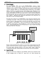
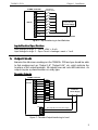
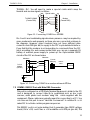
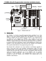
T100MX+ PLCs
Chapter 1 : Installation
Members of the T100MX+ differ only in their digital ON/OFF I/O combination. We
will be introducing a few standard models from 32 to 128 I/Os. Special I/O
combinations can also be custom-made for OEM customers requiring more
than 300 PLCs per year. Models of T100MX+ PLC are defined as follows:
T 1 0 0 M X - 3
CPU Type
2
No. of Inputs
2
4
R
+
No. of Outputs With some
Relay Outputs
In the above example T100MX-3224+ means that the PLC has 32 ON/OFF type
inputs and 24 ON/OFF type outputs. The “R” indicates that some of the outputs
are relay type. Models with only transistor-outputs do not carry the “R” label. If
you include the 8 channels of analog I/Os, the PLC will have a total of 32 + 24+
8 = 64 I/Os.
2. Physical Mounting & Wiring
The compactly designed T100MX+ PLCs can be easily installed in many kinds
of plastic or metal enclosures. You need to use 4, 6 or 8 PCB standoffs (or some
screws and nuts) to support the controller and to fasten it to a console box.
Screw terminals are provided for quick connection to all input and output wires.
In addition, each block of screw terminals can easily be detached from the
controller body, enabling easy replacement of the controller board when
necessary.
Maximum AWG 24 wire
Insulated crimp
ferrules
Tightening
screw
Connecting-pin strip
Flat-head
screw driver
Figure 2 - Removing screw terminal block
Detachable screw terminal blocks are provided for quick connection to all
inputs, outputs and power supply wires. Since the terminal block is inserted
vertically to the board surface, you need to remove the terminal block before
you can start wiring. Insert a small flat-head screw-driver underneath the
terminal block and apply even pressure to raise the terminal block until it
becomes loosened from the connecting-pin strip, as shown in Figure 2.
2