1
T100MX+ PLCs
Chapter 1 : Installation
All T100MX+ PLCs employ “sink” (NPN) type power transistor outputs that turn ON
by sinking current from the load to the ground. Every 8 outputs are grouped
together into a single strip of detachable screw terminal and they share a single
GND (ground) terminal. These "GND" terminals provide the return paths of the
sunk current back to the power source and hence must be connected to the
0V terminal of the power supply.
IMPORTANT
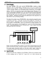
To minimize the effect of switching noise, use a separate pair of cables to
connect the "I/O Power" terminal to the power supply. If many high current loads
are to be switched, then you should also use a separate cable to connect
each "GND" terminal to the 0V of the power supply. That is, each ground should
be terminated only at the power supply source. Parallel connection from
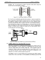
terminal to terminal is not recommended, as illustrated in the following diagram.
Output Terminals
Output Terminals
Power Supply
GND
Power Supply
GND
-
-
Figure 8 - Preferred Wiring Method of GND terminals
Transistor Outputs Electrical specifications:
Output #5 to #8
Output Driver type
Maximum Output Current:
Continuous Output Current
(with all other outputs ON)
Output Voltage when OFF
Output Voltage when ON:
@ Iout = 700 mA
NPN Darlington
Power Transistors
All Other Transistor Outputs
(1- 4, 8-16, ...)
N-Channel power MOSFET
with low rDS = 1 Ω
1.0A
1.0A
250mA
350mA
Resistor pulled up to V+ of the I/O power
1.2V
0.7V
6