1
CM4 Four-Point Continuous Monitor
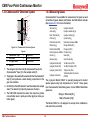
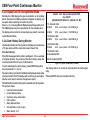
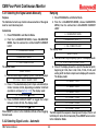
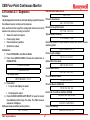
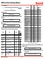
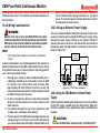
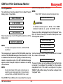
2 switches off the pump and accesses the pump limits settings.
Selecting 3 is for Sample Line Integrity Option, (see Section 10.3).
2. Select 1 to toggle the pump On. A new pressure counts
value is displayed. This value is the “normal reading.” You
will use this value as a base to set the High and Low Limits.
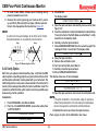
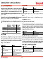
3. Select 2 to set the High and Low limits. The display will show:
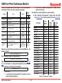
LIMITS HI = 500 LO = 400
The cursor flashes under the first number of the high limit. Using
the arrow keys, moves the cursor location left or right. Decimal
values 0-9 can also be entered.
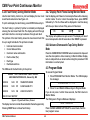
4. Set the High Limit value. The recommended default value
is 52 +/-12 counts above the “normal reading,” allowing the
instrument as installed to exhaust the total flow up to a head
pressure of +1 PSIG (52 torr). Vacuum levels that are above
the set point may indicate high exhaust pressure, blocked
exhaust, low capacity pump, or low supply vacuum. The
total flow is reduced, affecting transport times and flow rate
through the Chemcassette®. This is due to low differential
pressures across the orifice of each point.
5. Set the Low Limit value. The default value recommended is
52 +/-12 counts below the “normal reading,” allowing the
instrument to indicate a 25% loss of total flow. Vacuum levels
below the limit indicates too much vacuum is detected.
Possible causes for this condition are blocked filters at the
end of a sample line, internal blocking of the orifices, or a
blocked sample line. The vacuum level is produced by pump
capacity and the limiting orifice used in each point. Adding
four 300-foot sample lines increases the total vacuum
level, changing the count value approximately -15 counts
or 1/2 inch HG (12 torr).
CM4 Technical Manual
Note:
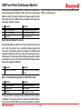
Setting the limits to 0 will disable the fault being issued.
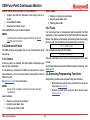
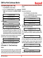
Once the high and low limits have been selected, press ENTER to
store the values. The message “Pump Limits Updated” is printed
along with the Time/Date/Serial Number. Pressing ESCAPE will exit
the routine, returning the values to pre-programmed levels and not
printing any message.
The pump limits are also incorporated into the Service Mode
Diagnostics 4.3 printout. The pump limits are also listed on the
system configuration printout (2.6 Print Config).
Note:
If at any time the system is reset to factory defaults (Function
4.4–RESET SYSTEM), this procedure will need to be redone
since the low and high limit values will be reset to factory
default values.
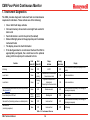
8.10 Function 4.9 – Reboot
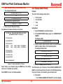
A reboot function has been added to allow rebooting without cycling
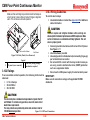
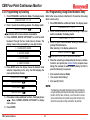
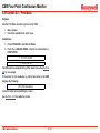
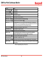
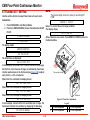
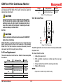
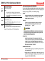
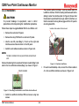
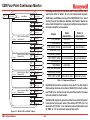
Model CM4 power. Figure 8-5 shows the prompts displayed.
Display
Function
9 - REBOOT
Reboot
ENTER CODE 9XXXX
Appears only if menu password is enabled via Section 3.6.2
SAVE CONFIG 1=Y 0=NO
Offer to backup configuration
CONF SAVED INTERNALLY
Confirms that a backup was performed. Also a line will be printed:
CONFIGURATION SAVED INTERNALLY
RESTARTING
CM4
8-13
Reboot display
Figure 8-5: Reboot Function Prompts