1
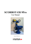
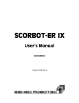
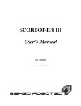
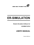
STANDARD OPERATING PROCEDURE AND SAFETY
GUIDE FOR SCORBOT - ER V
(Located in Rm. H -12 A Head Hall)
Prepared
August 3, 2010
Table of Contents
1. Scope ........................................................................................................................................4
1.1 Objective ............................................................................................................................4
1.2 Regulations ........................................................................................................................4
2.Apparatus Overview and objective ...........................................................................................4
2.1 Apparatus overview ...........................................................................................................4
3. Hazards and control evaluation ..............................................................................................12
3.1 Possible fire event ............................................................................................................12
3.2 Ventilation........................................................................................................................13
3.3 Kinetic, thermal & accoustic............................................................................................13
3.4 Electrical ..........................................................................................................................13
3.5 General, physical & equipment concerns ........................................................................14
3.6 Access ..............................................................................................................................15
3.7 Training ............................................................................................................................15
3.8 Personal protective equipment .........................................................................................15
4. Operation................................................................................................................................15
4.1 Qualified personnel ..........................................................................................................15
4.2 Experiment preparation ....................................................................................................15
4.3 Lab instructions ................................................................................................................17
4.4 Operating procedure.........................................................................................................17
5. Inspection and maintenance ...................................................................................................20
5.1 Operational & Periodic inspections .................................................................................21
6. Typical test .............................................................................................................................22
Appendix A: SCORBOT - ER V plus User’s Manual ...............................................................23
Appendix B: Introduction to the SCORBOT - ER V ................................................................24
Appendix C: I/O Communication with the SCORBOT - ER V ................................................25
Appendix D: SCORBOT overview ...........................................................................................26
Appendix E: ATS Terminal command reference ......................................................................27
ii
H -12 A, Head Hall floor plan
3
1. Scope
1.1 Objective
This standard operating procedure is intended to provide operating
instructions and safety information for the Department of Mechanical
Engineering’s SCORBOT - ER V Plus located in H - 12 A, in Head Hall.
This document is intended as a guideline and supplement to proper training
that must be provided by qualified personnel before the robot is operated.
The aim of this document is to ensure that safe work practices have been
developed for the robot experimental work. This SOP is primarily concerned
with the robot’s operating procedure, hazards involved with its operation and
safety precautions that must be taken to avoid injuries.
1.2 Regulations
This document has been developed in accordance with the Environmental
Health and Safety Office of the University of New Brunswick.
2. Apparatus Overview and Objective
2.1 Apparatus overview
The arm of SCORBOT - ER V Plus has 5 degrees of freedom (joints). The
five joints of the arm are the base, shoulder, elbow, pitch and roll. The
joints move independently when the teach pendant is put in joint mode and
in Cartesian coordinates plane when the teach pendant is put in XYZ mode.
Each joint has a servo motor. The end of the arm has a two jaw servo
motor controlled gripper which opens and closes to drop or grip a wooden
block and is controlled via teach pendant as well as ATS (Advanced
Terminal Software).
ATS is a terminal emulation program that provides a user interface to the
controller. It also provides a means of configuring the controller and
backing up the user’s programs, positions and variables to a floppy, CD or
hard drive. Please refer to Appendix “B” (Introduction to the SCORBOT ER V, section 1.7) to see the list of available terminal commands. ATS uses
ACL (Advanced control language) to communicate with the controller.
Please refer to Appendix “A” (SCORBOT - ER V Plus User’s Manual,
Chapter 7) to see the details of programming with ACL.
4
The end of the arm has another joint known as roll that controls the rolling
motion of gripper. The pitch and roll motion of gripper are mechanically
independent. These two motions are controlled by two different servo
motors through a differential-like arrangement of bevel gears.
The sixth degree of freedom is added to the SCORBOT as a linear motion
below the base which is also controlled by the teach pendant and ATS. This
greatly expands the robots reachable workspace.
The SCORBOT has a controller that supplies 12 VDC power to the robot. It
has 16 digital inputs and outputs and has a 128 KB of battery backed up user
RAM for storing positions, variables and programs. The controller has
EMERGENCY and MOTOR switches.
Please refer to Appendix “A” (SCORBOT - ER V plus User’s Manual) to
see the figured details and description of all the components of SCORBOT.
5
Figure 1: SCORBOT Controller
6
Figure 2: Controller power pilot light and motor switches
7
Figure 3: Controller EMERGENCY switch
8
Figure 4: SCORBOT teach pendant
9
Figure 5: Servo motors controlling the joints motion
10
Figure 6: SCORBOT base and shoulder joints
11
Figure 7: Gripper joint
The SCORBOT is also provided with a Geneva wheel/indexing table. Its
rotating motion is controlled by the ATS. The test blocks are mounted on
Geneva wheel and the SCORBOT/manipulator is assigned the task to pick
and drop the test block to the Geneva wheel using teach pendant or ATS.
Please refer to Appendix “C” (I/O Communication with the SCORBOT - ER
V, Indexing table) to see the details and description of Geneva wheel
operation.
The objective of the SCORBOT - ER V Plus is to familiarize students with
the operation of the SCORBOT - ER V manipulator using the teach pendant
12
and ATS by using its native programming language, ACL. They also learn
how to communicate with the external devices using simple inputs and
outputs of the SCORBOT - ER V controller. Please refer to Appendix “B”
(Introduction to the SCORBOT - ER V) and Appendix “C” (I/O
Communication with the SCORBOT - ER V) to see the details of
experimenting with the SCORBOT - ER V.
Figure 8: The Geneva wheel
13
3. Hazards and Controls Evaluation
3.1 Possible fire event
In the event of fire, evacuate the room immediately. Pull the nearest fire
alarm (see H-12 A floor plan). Should you return to attempt to extinguish the
fire, do not do so alone and make only one attempt to do so. If unsuccessful,
leave the lab immediately. If successful stay at the scene and have someone
alert the Security and Traffic department (ph. # 4830) and the Environmental
Health and Safety office (ph. # 5075). Please refer to H-12 A, Head Hall
floor plan to see the locations of fire extinguishers, fire alarm pull station
and first aid kit.
3.2 Ventilation
There are no ventilation exhaust fans for fume hoods. The room is centrally
ventilated as fresh air is being introduced at all times into the room. An air
ventilation system is not a requirement for the operation of SCORBOT - ER
V Plus.
3.3 Kinetic, Thermal and Acoustic
The SCORBOT - ER V is associated with very real kinetic hazards. The
arm and its joint movement can be very rapid (in fact faster than any
human reflex reaction), so no person or object should be within the
robot’s workspace while it is operational. The immediate area surrounding
this workspace should be delineated with yellow and black striped safety
matting to define the Physical Hazard danger zone. When possible, the user
should also reduce the speed of robot movement by way of the teach pendant
or ATS. The operator must stay on the alert at all times and be prepared to
press the “EMERGENCY” button while the robot is operational. If the robot
is set at a very high speed, then the impulse on robot (due to high
acceleration at the start of motion) will cause the teach pendant to deactivate
automatically for user safety. Please refer to Appendix “D” (SCORBOT ER V overview) to see how to adjust the speed of SCORBOT by using
teaching pendant. Refer to Appendix “E” (ATS Terminal command
reference) to see the command to change the speed of robot. There are
several exposed gears and drive belts on this apparatus. Do not wear jewelry,
loose clothing or long hair around this equipment.
14
The robot and its components are not associated with elevated temperatures
so it does not pose thermal threat to the user.
The apparatus is not associated with any acoustic hazard.
3.4 Electrical
The SCORBOT - ER V Plus is electrically powered although it does not
pose any electrical threat to the user, if handled carefully. The computer and
controller are connected to the main power supply as shown in Figure 9.
Always check the apparatus for bare, frayed or cut electrical cables before
operating it. Please see Figure 9 to see the main electrical outlet powering
this apparatus.
15
Figure 9: Main power supply to controller and computer
3.5 General, physical and equipment concerns
Always return both the arm and the linear track to “HOME” after powering
ON the controller or pressing the EMERGENCY button. To “HOME” the
robot, you must key in “ Run 0 [ENTER]”. Please refer to Appendix “D”
(SCORBOT - ER V overview, figure D.1) to see the Homing position of the
robot.
Never define a position that can cause the arm to collide with itself or
damage its joints. If it appears that the arm is about to collide with
16
something then do not hesitate to press the EMERGENCY or MOTORS
button.
Start the operation with low speed and never operate the SCORBOT under
influence of drugs or alcohol. Remember that the robot can be programmed
to react faster than any possible human reflect reaction.
3.6 Access
All personnel in the H - 12 A lab should be preauthorized by the faculty
supervisor or under the supervision of authorized personnel (lab technician
or teacher assistant). No person, other than the faculty supervisor or
specifically authorized personnel, is permitted to make alterations to, or to
experiment with the SCORBOT - ER V Plus.
3.7 Training
All individuals using the SCORBOT - ER V Plus shall be required to
receive training in the proper operation and maintenance of the apparatus
and its controls. Training will include such topics as the complete operation
and control of the SCORBOT - ER V Plus. Training programs shall be
administered only by qualified personnel at UNB.
3.8 Personal Protective Equipment
No open toed shoes are permitted while using SCORBOT - ER V plus.
Impact resistant eyewear is optional but preferable around any moving parts.
4. Operation
4.1 Qualified Personnel
These notes in the operation section will provide a guideline to the
individual that has been trained by qualified personnel to operate the
SCORBOT - ER V Plus. Only after the individual has been trained and feels
confident with the robot operating procedure should he or she attempt to
operate the SCORBOT - ER V using these notes. Do not proceed if you are
not properly trained or are unsure in any manner of the safe operation and
safety concerns of this equipment.
17
4.2 Experiment preparation
Following steps should be carried out to prepare for the experiment:
1. Ensure that the test bench surface is clean.
2. Ensure that the SCORBOT - ER V Plus connection to main power supply
is secure and tight (see Figure 9).
3. Verify that all proper connections are made with the controller, PC and
teach pendant.
4. Log on to the personal computer that is connected to SCORBOT
controller and Geneva wheel/indexing table.
18
Figure 10: SCORBASE software window displaying ATS HELP
on command screen
5.
Place the wooden blocks on the slots of indexing table/Geneva wheel
19
4.3 Lab Instructions
4.3.1 Instructor Responsibilities
The SOP for the SCORBOT - ER V Plus should be read and well
understood. This document provides all the necessary information regarding
the apparatus operation, hazards involved & safety precautions to be taken
while using the apparatus. The lab instructor shall remain in the room while
the experiment is in progress. After the students have fully assembled and
before any explanation has begun, the instructor should relay all safety
precautions and hazards as outlined in Section 3. Inform all students that
they must contact the instructor if any problems any problems or concerns
should arise during the experiment. Make the group aware of the fire
extinguishers locations, fire alarm pull station and exit. Any student from the
group missing his personal protective equipment should not be allowed by
the instructor to enter the laboratory H - 12 A and proceed with the
experiment.
4.4 Operating Procedure
4.4.1 Operation of SCORBOT - ER V
After preparing for the experiment as mentioned in Section 4.2, follow these
steps to operate and perform the experiment with the robot:
1. Turn the controller power ON (see Figure 11). This will illuminate the
yellow pilot light indicating that the SCORBOT is powered ON.
20
Figure 11: Controller Power ON/OFF switch
2. The Red emergency pilot light should be OFF. If it is not then turn off
emergency switch.
3. Turn the controller Motors switch to ON. This will illuminate the
Green pilot light indicating that all the motors of robot are powered
up.
4. Press the “Control ON/OFF” button on teach pendant (see Figure 4) to
turn ON the communication channel between user/teach pendant and
SCORBOT. Alternatively, use the computer (SCORBASE program)
21
to communicate with the robot. Please refer to Figure 10 to see the
command screen.
5. “Home” the robot. To home you must key in “Run 0 [Enter]”.
6. To move each joint of the robot independently in either direction, put
the robot in “JOINT” mode and key in:
a) Base
b) Shoulder
c) Elbow
d) Pitch
e) Roll
7. To move the robot in the XYZ Cartesian coordinate plane, put the
robot in XYZ mode and key in:
a) X+ and Xb) Y+ and Yc) Z+ and Zd) Pitch
e) Roll
8. To vary the speed of robot movement, key in: Speed <#> [Enter],
where 1≤#≤100. Note that the default speed is = 50 %
9. To record any position of robot, ensure that the group select mode is
A and key in: Record position 11 [Enter].
10.To attain the recorded position of robot, key in: Go position 11.
11. Key in: Open/close gripper to open or close the jaws of the gripper.
4.4.2 Writing and Running Computer Program
Please refer to Appendix “D” (SCORBOT - ER V Plus overview, writing
and running programs) to see how to write and run a program using
SCORBASE software, to operate the robot by SCORBASE software and
monitor the movements of the robot. Please see Figure 10 to see the HELP
command window of ATS. Please also refer to Figure D.4 (SCORBASE
22
main screen) and figure D.5 (Edit program screen) in Appendix “D” to see
the description of the software.
4.4.3 Shutdown
Normal Shutdown
Perform the following sequence to shutdown the apparatus:
1. Key in: “Run 0 [Enter]” to Home the robot.
2. Press control ON/OFF to disable the teach pendant and its
communication with the robot.
3. Turn OFF the motors by pressing the Motors Switch. The Green light
will turn OFF indicating no power supply to the motors.
4. Turn OFF the controller power (See figure 11). The Yellow light will
turn OFF indicating no power supply to the controller.
Emergency Shutdown
In case of emergency, press the Emergency Switch on controller to turn OFF
the power supply to all the motors and to the robot.
5.0 Inspection and Maintenance
The following inspections will be performed before operating the robot:
1. Before powering ON the robot, check the following:
•
•
•
•
The installation meets all safety standards.
The robot is properly bolted to the work surface.
All cables are properly and securely connected.
The teach pendant and any peripheral devices which will be used are
properly connected to the controller.
• No person or object is within the physical hazard zone workspace of
robot.
23
2. After powering ON the apparatus, check the following:
• The power and motor pilot lights illuminated.
• The fan in front of the front panel rotates and draws air into the
controller.
• The fan in the rear panel of the controller extracts air from the
controller.
• All green pilot lights on the rear of the controller panel illuminate.
• No unusual noises are heard.
• No unusual vibrations are observed.
• There are no obstacles are in the robots workspace.
3. Activate the robots Homing procedure and check the following:
• Robot movement is normal.
• No unusual noise is heard or vibration is observed.
• Robot reaches Home position in every axis.
5.1 Periodic & Operational Inspections
Visual inspections are the responsibility of the person who is conducting
experiment on a regular basis with the SCORBOT - ER V Plus and should
be carried out every time before operating the apparatus. A complete
periodic inspection of the apparatus shall be performed by the person who is
conducting experiments on a regular basis with this apparatus. That same
person will alert the faculty supervisor of any deficiencies in the apparatus.
The deficiencies such as those listed below shall be examined during both
the periodic & operational inspection. The faculty supervisor will determine
if the deficiencies will affect the safe operation of the apparatus. Please
check for the following:
a. Worn or damaged leads, cables and rubber components.
b. Worn or loose bolts and screws in the robot arm
c. Worn, damaged or loose robot arm belts. Upon pressing the belt, the
slack should not be greater than 2 mm in tension (see Figure 12).
24
Figure 12: Belt tension
d. Excessive backlash in the base axis
6.0 Typical Tests
The actual test procedure will be outlined in the lab script as issued by the
professor. A typical test includes writing a program to communicate with the
robot to perform a task assigned by the user. Please refer to Appendix “B”
(Introduction to the SCORBOT - ER V) and Appendix “C” (I/O
Communication with the SCORBOT - ER V) to see the details of
experiment with SCORBOT - ER V robot.
25
Appendix ‘A’
26
Appendix ‘B’
27
Appendix ‘C’
28
Appendix ‘D’
29
Appendix ‘E’
30