1
THE DINI GROUP
LOGIC Emulation Source
User Manual
DNMEG_ARM_TILE
(REV2)
LOGIC EMULATION SOUR CE
DNMEG_ARM_TILE (REV2) User Manual
Version 2.0
Date of Print April 23, 2010
ã The Dini Group
7469 Draper Avenue
La Jolla, CA92037
Phone 858.454.3419 • Fax 858.454.1279
[email protected]
www.dinigroup.com
Copyright Notice and Proprietary Information
Copyright © 2010 The Dini Group. All rights reserved. No part of this copyrighted work may be
reproduced, modified or distributed in any form or by any means, without the prior written permission of
The Dini Group.
Right to Copy Documentation
The Dini Group permits licensee to make copies of the documentation for its internal use only. Each copy
shall include all copyrights, trademarks, disclaimers and proprietary rights notices.
Disclaimer
The Dini Group has made reasonable efforts to ensure that the information in this document is accurate and
complete. However, The Dini Group assumes no liability for errors, or for any incidental, consequential,
indirect, or special damages, including, without limitation, loss of use, loss or alteration of data, delays, or
lost profits or savings, arising from the use of this document or the product which it accompanies.
Table of Contents
INTRODUCTION ............................................................................................................................................................................................................................1
1
2
3
4
5
ABOUT THE DNMEG_ARM_TILE DAUGHTER CARD .......................................................................................................................................1
DNMEG_ARM_TILE (REV2) DAUGHTER CARD FEATURES ...........................................................................................................................2
PACKAGE CONTENTS:............................................................................................................................................................................................3
INSPECT THE BOARD..............................................................................................................................................................................................4
ADDITIONAL INFORMATION ..................................................................................................................................................................................4
GETTING STARTED .....................................................................................................................................................................................................................6
1
1.1
1.2
2
2.1
2.2
3
3.1
4
4.1
4.2
5
5.1
5.2
5.3
5.4
5.5
BEFORE YOU BEGIN ..............................................................................................................................................................................................6
Configuring the Programmable Components .............................................................................................................................................................. 6
Warnings ........................................................................................................................................................................................................................ 6
PREPARING THE ARM C ORE TILE ........................................................................................................................................................................7
Why is this Necessary? .................................................................................................................................................................................................. 7
Removing Resistors........................................................................................................................................................................................................ 7
PREPARING THE DNMEG_ARM_TILE (REV2) .................................................................................................................................................8
Power Options / Jumper Settings ................................................................................................................................................................................. 8
MATING THE DNMEG_ARM_TILE (REV2) WITH THE ARM C ORE TILE ......................................................................................................9
Aligning the Headers ..................................................................................................................................................................................................... 9
Press Down Firmly ...................................................................................................................................................................................................... 10
USING THE REFERENCE DESIGN .........................................................................................................................................................................10
Initial Setup before Applying Power .......................................................................................................................................................................... 10
Serial COM Setup using Hyperterminal .................................................................................................................................................................... 11
Running the Reference Design .................................................................................................................................................................................... 12
Running the Loopback Design .................................................................................................................................................................................... 13
Resetting a Design ....................................................................................................................................................................................................... 13
PROGRAMMING/CONFIGURING THE HARDWARE ......................................................................................................................................................14
6
7
INTRODUCTION ....................................................................................................................................................................................................14
CONFIGURATION OPTIONS ..................................................................................................................................................................................14
7.1
Configuring the FPGA using JTAG............................................................................................................................................................................ 15
7.1.1
Setup ..................................................................................................................................................................................................................... 15
7.1.2
Configuring the FPGA ........................................................................................................................................................................................ 15
7.2
Configuring the FPGA using Xilinx PROM ............................................................................................................................................................... 16
7.2.1
Setup ..................................................................................................................................................................................................................... 17
7.2.2
Configuring the FPGA ........................................................................................................................................................................................ 17
HARDWARE DESCRIPTION ....................................................................................................................................................................................................19
8
9
10
OVERVIEW............................................................................................................................................................................................................19
XILINX SPARTAN 3 FPGA ...................................................................................................................................................................................21
PERIPHERALS .......................................................................................................................................................................................................21
10.1
SDRAM – PC100/PC133 ........................................................................................................................................................................................ 21
10.2
SSRAM ...................................................................................................................................................................................................................... 22
10.3
FLASH ...................................................................................................................................................................................................................... 22
10.4
AC97 Audio .............................................................................................................................................................................................................. 22
10.5
Ethernet PHY - 10/100/1000base-T (not available with DN7020k10 or DN9000k10) ...................................................................................... 22
11
CLOCK GENERATION ...........................................................................................................................................................................................22
11.1
Clock Methodology.................................................................................................................................................................................................. 22
11.2
Daughter Card Clocks ............................................................................................................................................................................................ 25
11.2.1
Connections between the FPGA and the Daughter Card Header Clocks ........................................................................................................ 25
12
ARM HEADERS ....................................................................................................................................................................................................25
13
GENERAL PURPOSE HEADERS .............................................................................................................................................................................35
14
14.1
14.2
14.3
15
15.1
15.2
15.3
16
17
18
19
20
20.1
20.2
20.3
20.4
20.5
20.6
21
21.1
APPENDIX
22
23
LED INDICATORS ................................................................................................................................................................................................37
User LED’s .............................................................................................................................................................................................................. 37
Configuration DONE LED...................................................................................................................................................................................... 38
Power Supply Status LED’s .................................................................................................................................................................................... 38
MEMORY ..............................................................................................................................................................................................................39
SRAM ........................................................................................................................................................................................................................ 39
DRAM ....................................................................................................................................................................................................................... 41
FLASH ...................................................................................................................................................................................................................... 43
PS/2 KEYBOARD AND MOUSE.............................................................................................................................................................................44
AC97 ....................................................................................................................................................................................................................44
RS232 PORT .........................................................................................................................................................................................................45
JTAG ....................................................................................................................................................................................................................46
DAUGHTER CARD HEADERS ...............................................................................................................................................................................47
Daughter Card clocking.......................................................................................................................................................................................... 47
Daughter Card Header Pin Assignments ............................................................................................................................................................... 47
FPGA to Daughter Card Header IO Connections ................................................................................................................................................ 49
Power and Reset ...................................................................................................................................................................................................... 54
Insertion/Removal of Daughter Card ..................................................................................................................................................................... 55
MEG Array Specifications ...................................................................................................................................................................................... 56
MECHANICAL .......................................................................................................................................................................................................57
Dimensions ............................................................................................................................................................................................................... 57
58
APPENDIX A: UCF FILE ......................................................................................................................................................................................58
APPENDIX B: USING A THIRD-PARTY ARM DEBUGGER ..................................................................................................................................58
List of Figures
Figure 1 - DNMEG_ARM_TILE (REV2) Daughter Card .......................................................................................................................................................................................1
Figure 2 - DNMEG_ARM_TILE (REV2) Daughter Card Block Diagram ....................................................................................................................................................... 20
Figure 3 - Clocking Block Diagram .............................................................................................................................................................................................................................. 23
Figure 4 – Xilinx JTAG Connector .............................................................................................................................................................................................................................. 46
Figure 5 – Multi-ICE JTAG Connector ...................................................................................................................................................................................................................... 46
Figure 6 - Daughter Card Header Pin Assignments.................................................................................................................................................................................................. 48
List of Tables
Table 1 – Additional Information ....................................................................................................................................................................................................................................4
Table 2 – Jumper Settings ..................................................................................................................................................................................................................................................8
Table 3 – FPGA Clocking............................................................................................................................................................................................................................................... 24
Table 4 - Connections for Daughter Card Header Clocks ...................................................................................................................................................................................... 25
Table 5 – ARM Header Connections ........................................................................................................................................................................................................................... 25
Table 6 – Signals on S1 and S2 ...................................................................................................................................................................................................................................... 35
Table 7 – General Purpose Headers ............................................................................................................................................................................................................................. 35
Table 8 – User LED’s ...................................................................................................................................................................................................................................................... 37
Table 9 – FPGA_DONE LED ..................................................................................................................................................................................................................................... 38
Table 10 – Power Supply Status LED’s ....................................................................................................................................................................................................................... 39
Table 11 – SRAM Connections ..................................................................................................................................................................................................................................... 39
Table 12 – DRAM Connections .................................................................................................................................................................................................................................... 41
Table 13 – FLASH Connections ................................................................................................................................................................................................................................... 43
Table 14 – PS/2 Connections ........................................................................................................................................................................................................................................ 44
Table 15 – AC97 Connections ....................................................................................................................................................................................................................................... 44
Table 16 – Signals on S3 .................................................................................................................................................................................................................................................. 45
Table 17 - Connections between FPGA and the RS232 Port ................................................................................................................................................................................ 45
Table 18 - Daughter Card Header IO Connections .................................................................................................................................................................................................. 49
Table 19 – Daughter Card Reset Signal (DC_RST_N) ............................................................................................................................................................................................ 54
I N T R O D U C T I O N
Chapter
1
Introduction
This User Manual accompanies the DNMEG_ARM_TILE (REV2)
Daughter Card. For specific information regarding the Spartan part, please
reference the datasheet on the Xilinx website.
1 About the DNMEG_ARM_TILE Daughter Card
The DNMEG_ARM_TILE (REV2) Daughter Card provides a development platform
for designing and verifying applications targeted for use with an ARM processor. This
board provides designers access to commonly used peripherals and full utility of the
ARM processor on a connected Core Tile. The DNMEG_ARM_TILE (REV2)
Daughter Card can operate in standalone mode or in conjunction with one of the Dini
products that houses a 400 pin MEG-Array Daughter card header, e.g. DN7020k10.
Figure 1 - DNMEG_ARM_TILE (REV2) Daughter Card
DNMEG_ARM_TILE User Manual
www.dinigroup.com
1
I N T R O D U C T I O N
2 DNMEG_ARM_TILE (REV2) Daughter Card
Features
DNMEG_ARM_TILE (REV2) Daughter Card features the following:
· AHB Interface
o The AHB interface from the ARM Core Tile is connected both to the
on-board Spartan FPGA and to the MEG-Array connector. This
allows for standalone usage, base-board only usage, or a combination
of base-board and on-board FPGA usage.
o Sample RTL code is provided to give each peripheral on the
DNMEG_ARM_TILE (REV2) an AHB interface, making the
peripherals easily accessible from the ARM processor.
· Microprocessor Peripherals
o Xilinx Spartan 3 FPGA (3S5000-S)
o SDRAM – PC100/PC133: 16M x 32
o SSRAM: 512K x 36
o FLASH: 2M x 16
o AC97 Audio
o Keyboard/Mouse
o RS232
o Ethernet PHY – not available with DN7020k10 or DN9000k10
· Flexible Clock Resources
o AHB clock can be generated using Spartan and on-board 100 MHz
clock, or from base-board. This allows for AHB frequencies from 1100 MHz.
o Can use HCLK, Global Clock, retimed or delay-matched clocks for
clocking Core Tile.
· FPGA Configuration
DNMEG_ARM_TILE User Manual
www.dinigroup.com
2
I N T R O D U C T I O N
o On-board Xilinx PROM for automatic configuration.
o JTAG for configuration of Xilinx Spartan and PROM. Xilinx JTAG
cable provided.
· ARM Configuration
o Through a combination of switches and FPGA signals, all init and
run-time configuration signals for the ARM processor can be
programmed.
o JTAG interface to the ARM Core Tile is provided, allowing third-party
debuggers / emulators to communicate with the ARM processor.
· User LED’s (x32)
· General Purpose I/O headers
· Onboard distributed Power Supplies
· MEG-Array (400 pin) interface to Dinigroup base-boards
· Full support for embedded Logic Analyzers
o ChipScopeTM Pro Analyzer
· RS232 Port, 10 pin Header – MicroBlaze Applications
· Stand Alone operation, requires an external +12V/+5V ATX power supply
3 Package Contents:
Before using the kit or installing the software, be sure to check the contents of the kit
and inspect the board to verify that you received all of the items. If any of these items
are missing, contact The Dini Group before you proceed. The DNMEG_ARM_TILE
(REV2) Daughter Card kit includes the following:
· RS232 IDC Header to Female DB9 Cable Assembly
· RS232 Serial Cable Assembly, 6ft, F/F (DB9)
· CD ROM containing:
o Spartan Reference Design (Verilog)
DNMEG_ARM_TILE User Manual
www.dinigroup.com
3
I N T R O D U C T I O N
o User Manual (pdf format)
o Schematic (pdf format)
o Component Datasheets (pdf format)
Optional items that support development efforts (not provided):
ü
Xilinx ISE software and Xilinx Platform Cable USB download cable
ü
ARM debugging cable / emulator (JTAG)
4 Inspect the Board
Place the board on an anti-static surface and inspect it to ensure that it has not been
damaged during shipment. Verify that all components are on the board and appear
intact.
5 Additional Information
For additional information, please visit http://www.dinigroup.com/. The following
table lists some of the resources you can access from this website. You can also directly
access these resources using the provided URLs.
Table 1 – Additional Information
Resource
Description/URL
User Manual
This is the main source of technical information. The manual
should contain most of the answers to your questions
Demonstration
Videos
MEG-Array Daughter Card header insertion and removal video
Dini Group
Web Site
The web page will contain the latest user manual, application notes,
FAQ, articles, and any device errata and manual addenda. Please
visit and bookmark: http://www.dinigroup.com
Spartan 3 User
Guide
Pages from Spartan 3 User Guide, which contains device-specific
information on Xilinx device characteristics
ARM Core Tile
Datasheet
Information about the ARM Core Tile, found here:
http://www.arm.com/miscPDFs/7843.pdf
AMBA AHB
Specification
A description of the signals on the AHB bus, found here:
http://www.arm.com/products/solutions/AMBA_Spec.html
DNMEG_ARM_TILE User Manual
www.dinigroup.com
4
I N T R O D U C T I O N
Resource
Description/URL
E-Mail
You may direct questions and feedback to the Dini Group using
this e-mail address: [email protected]
Phone Support
Call us at 858.454.3419 during the hours of 10:00am to 5:00pm
Pacific Time.
FAQ
The download section of the web page may contain a document
called DNMEG_ARM_TILE (REV2) Frequently Asked
Questions (FAQ). This document is periodically updated with
information that may not be in the User’s Manual.
DNMEG_ARM_TILE User Manual
www.dinigroup.com
5
G E T T I N G
S T A R T E D
Chapter
2
Getting Started
Congratulations on your purchase of the
DNMEG_ARM_TILE (REV2) Daughter Card. The
remainder of this chapter describes how to start using the
board.
1 Before You Begin
1.1 Configuring the Programmable Components
The DNMEG_ARM_TILE (REV2) Daughter Card has been factory tested and preprogrammed to ensure correct operation. The user does not need to alter any jumpers
or program anything to see the board work.
1.2 Warnings
· Connecting to the ARM Core Tile – There are many different build options
for the Core Tile, some of which involve resistor links between voltage
sources. In order to prevent electrical damage to both the Core Tile and the
DNMEG_ARM_TILE (REV2), please read the section on Core Tile
preparation before mating the cards.
· Daughter Card Test Headers (Over Voltage) - The 400-pin daughter card
test headers are NOT 5V tolerant. Take care when handling the board to
avoid touching the components and daughter card connections due to ESD.
· ESD Warning - The board is sensitive to static electricity, so treat the PCB
accordingly. The target markets for this product are engineers that are familiar
with FPGAs and circuit boards. However, if needed, the following web page
has an excellent tutorial on the “Fundamentals of ESD” for those of you who
are new to ESD sensitive products:
http://www.esda.org/basics/part1.cfm
DNMEG_ARM_TILE User Manual
www.dinigroup.com
6
G E T T I N G
S T A R T E D
· Operating Temperature - Avoid touching the PTH012050WAZ power
supply modules (PSU1, PSU2, PSU3, PSU5, PSU6) as they operate at high
temperatures and may cause skin burns.
2 Preparing the ARM Core Tile
2.1 Why is this Necessary?
The ARM core tile has many different stuffing options, and must be customized to fit
a specific application. Our primary concern is the power connections that are, by
default, installed on the tile. R25 and R182 connect PVDDIO (AHB signal voltage) on
the Core Tile to 3.3V – we want to use our selectable on-board voltage of 2.5V or 3.0V
to comply with the electrical limits of modern FPGAs. R24 and R183 connect
PCCOY (expandable memory voltage) to 3.3V – we want to select from a variety of
voltage ranges on the DNMEG_ARM_TILE (REV2) for compliance with a wider
range of memory modules.
2.2 Removing Resistors
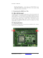
R25, R182, R24, and R183 need to be removed from the ARM Core Tile. Locations
of these resistors are indicated below.
DNMEG_ARM_TILE User Manual
www.dinigroup.com
7
G E T T I N G
S T A R T E D
3 Preparing the DNMEG_ARM_TILE (REV2)
3.1 Power Options / Jumper Settings
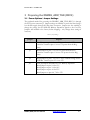
The preferred method for powering the DNMEG_ARM_TILE (REV2) is through
the ATX power connector J5. Jumper settings are available to power the board using a
host board’s supply through the Meg-Array connector. Jumpers are also available to
change the voltage for the AHB and Memory Expansion signals to the Core Tile.
Jumpers will installed at the factory before shipping – only change these settings if
necessary.
Table 2 – Jumper Settings
Jumper
Purpose
J2
Install Jumper on pins 2-3 to use 5V power from the ATX
connector. Install on pins 1-2 to use 5V power from the MegArray.
J3
Install Jumper on pins 2-3 to use 12V power from the ATX
connector. Install on pins 1-2 to use 12V power from the MegArray.
J4
Install Jumper on pins 1-2 to use 3V as the VDDIO voltage for the
AHB Bus. Install on pins 2-3 to use 2.5V.
J11
Leave all jumpers uninstalled for 1.2V Memory Expansion.
Install jumper on pins 2-4 for 1.5V.
Install jumper on pins 3-4 for 1.8V.
Install jumper on pins 4-6 for 2.5V.
Install jumpers on pins 4-6, 7-8 for 3.3V.
DNMEG_ARM_TILE User Manual
www.dinigroup.com
8
G E T T I N G
S T A R T E D
4 Mating the DNMEG_ARM_TILE (REV2) with the
ARM Core Tile
4.1 Aligning the Headers
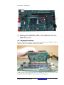
Begin by resting the far edge of the two horizontal headers on the ARM Core Tile on
headers J7 and J14 on DNMEG_ARM_TILE (REV2).
While keeping the far edge aligned, allow the ARM Core Tile to lay flat on top of the
DNMEG_ARM_TILE (REV2). The headers should be aligned.
DNMEG_ARM_TILE User Manual
www.dinigroup.com
9
G E T T I N G
S T A R T E D
4.2 Press Down Firmly
Press down firmly on each of the three ARM headers. Especially when dealing with
new ARM Core Tiles, these connectors can be stiff. Firmly pressing each segment of
each header is recommended.
5 Using the Reference Design
The Dini Group provides reference designs for the DNMEG_ARM_TILE (REV2) to
help the user get started with building applications:
· Reference – Loaded onto the board before shipped, allows for AHB
communication.
· Loopback – Allows for testing of DNMEG_ARM_TILE (REV2) peripherals
excluding AHB communication. Extra test cables are required (and not
included) to test AHB and Meg-Array headers.
5.1 Initial Setup before Applying Power
Attach the ATX Power Supply to the power header (J5) on the
DNMEG_ARM_TILE (REV2) Daughter Card. Connect the “Xilinx Platform Cable
USB” from the Test PC to the JTAG header (J16). Connect the serial cable from the
Test PC to the RS232 header (J26). Ensure that pin 1 location of the cable aligns with
pin 1 location on the PCB.
DNMEG_ARM_TILE User Manual
www.dinigroup.com
10
G E T T I N G
S T A R T E D
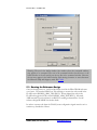
5.2 Serial COM Setup using Hyperterminal
Connect the RS232 Serial cable to a COM port on the host computer and the RS232
header (J26) on the DNMEG_ARM_TILE (REV2) Daughter Card. Configure
Hyperterminal to the following settings:
DNMEG_ARM_TILE User Manual
www.dinigroup.com
11
G E T T I N G
S T A R T E D
Warning: The text in the buffer window (the window above the command window)
may appear to be corrupted. The text in the command window should move to the
buffer window as the text scrolls past the top line in the command window. However,
the text may appear in the buffer window with missing characters or extra characters.
See Microsoft Help and Support, article ID: 274261
5.3 Running the Reference Design
Once the board powers on, it will load the bitfile stored in the Xilinx PROM and come
out of reset. The attached ARM Core Tile will begin to execute the code stored in the
FLASH on the DNMEG_ARM_TILE (REV2). When shipped, the code in the
FLASH will toggle the LEDs on the DNMEG_ARM_TILE (REV2). If desired,
AHB transactions can be initiated over RS232 by sending command files. See the
reference design README for further details.
In order to execute code from the FLASH, some configuration signals must be set in a
certain way, described as follows:
DNMEG_ARM_TILE User Manual
www.dinigroup.com
12
G E T T I N G
S T A R T E D
Table 3 – Reference Design Configuration Signals
Signal Name
XHEADER_BIGENDIN
XHEADER_INITRAM
XHEADER_VINITHI
Pin
S2.1
S2.2
S2.3
Switch State
OFF
ON
ON
Signal State
HIGH
LOW
LOW
5.4 Running the Loopback Design
Power-Up the DNMEG_ARM_TILE (REV2) Daughter Card and program the
Spartan FPGA with the loopback bitfile. See the section on programming the Spartan
FPGA for further detail. Open a Hyperterminal Window and view the output of the
design. The loopback design will run read/write tests on SRAM, DRAM, AHB
headers, and Meg-Array headers. It will also echo RS232 input and PS/2
Keyboard/Mouse input to the RS232 terminal, and detect when an ARM Core Tile is
attached. Because loopback cables are not provided for the AHB headers and MegArray header, errors for these tests will occur. This is a diagnostic test only for testing
interfaces to the DNMEG_ARM_TILE (REV2) peripherals.
5.5 Resetting a Design
Once a design is loaded, there are several ways to reset the design. If running
standalone mode, reloading the design with iMPACT is an easy way to do so. The
reset button S4 is a “hard” reset, and will cause the FPGA to reload from the PROM.
If running attached to a host board, the reset sent across the MEG-Array connector
can be used as a “soft”reset, meaning that it will reset the logic of the FPGA without
reconfiguring it.
DNMEG_ARM_TILE User Manual
www.dinigroup.com
13
P R O G R A M M I N G / C O N F I G U R I N G
T H E
H A R D W A R E
Chapter
3
Programming/Configuring
the Hardware
This chapter details the programming and configuration
instructions for the DNMEG_ARM_TILE (REV2)
Daughter Card.
6 Introduction
Spartan 3 devices are configured by loading application-specific configuration data—
the bitstream—into internal memory. Because Xilinx FPGA configuration memory is
volatile, it must be configured each time it is powered-up. The bitstream is loaded into
the device through special configuration pins. These configuration pins serve as the
interface for a number of different configuration modes (the following configuration
options are supported on this board):
· JTAG/Boundary-Scan
· Master-Serial from on-board Xilinx PROM
7 Configuration Options
This section lists detailed instructions for programming the Xilinx Virtex-5 FPGA
using iMPACT, Version 10.1 tools. Before configuring the FPGA, ensure that the
Xilinx software and the “Xilinx Platform Cable USB” driver software are installed on
the host computer.
Note: This User Manual will not be updated for every revision of the Xilinx ISE tools,
so please be aware of minor differences.
DNMEG_ARM_TILE User Manual
www.dinigroup.com
14
P R O G R A M M I N G / C O N F I G U R I N G
T H E
H A R D W A R E
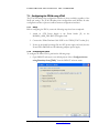
7.1 Configuring the FPGA using JTAG
The JTAG/Boundary-Scan configuration interface is always available, regardless of the
Mode pin settings. The JTAG/Boundary-Scan configuration mode disables all other
configuration modes to prevent conflicts between configuration interfaces.
7.1.1
Setup
Before configuring the FPGA, ensure the following steps have been completed:
1. Attach an ATX Power Supply to the Power header (J5) on the
DNMEG_ARM_TILE (REV2) Daughter Card.
2. Connect the “Xilinx Platform Cable USB” to the “FPGA JTAG” header (J16).
3. Power up the board by turning ON the ATX power supply and verify that the
Power LEDs DS2-DS6 are ON indicating adequate power supply.
7.1.2
Configuring the FPGA
To configure the Xilinx FPGA, perform the following steps:
1. Open iMPACT and create a new default project. Select “Configure devices
using Boundary-Scan (JTAG)” from the iMPACT welcome menu.
DNMEG_ARM_TILE User Manual
www.dinigroup.com
15
P R O G R A M M I N G / C O N F I G U R I N G
T H E
H A R D W A R E
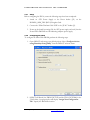
2. iMPACT will identify the PROM (XCF32P) and the FPGA (XC3S5000) in the
JTAG chain. A pop-up window will display “Assign New Configuration
File”. Click “Bypass” and specify the location for the FPGA bit file;
Select Device 2 in the “Device Programming Properties” window and click
“OK” to continue.
3. Right-click on the FPGA and select the “Program” option. A “Progress
Dialog” box will appear indicating programming progress.
4. The activation of the “CFG DONE” blue LED (DS7) indicates that the
FPGA configured successfully.
7.2 Configuring the FPGA using Xilinx PROM
The Master-Serial mode is designed so that the FPGA can be configured from a Xilinx
Flash PROM. The DNMEG_ARM_TILE (REV2) Daughter Card is populated with
an XCF32P, 32Mbit Flash PROM.
DNMEG_ARM_TILE User Manual
www.dinigroup.com
16
P R O G R A M M I N G / C O N F I G U R I N G
7.2.1
T H E
H A R D W A R E
Setup
Before configuring the FPGA, ensure the following steps have been completed:
1. Attach an ATX Power Supply to the Power header (J31) on the
DNMEG_ARM_TILE (REV2) Daughter Card.
2. Connect the “Xilinx Platform Cable USB” to the “JTAG” header (J2).
3. Power up the board by turning ON the ATX power supply and verify that the
Power LEDs DS2-DS6 are ON indicating adequate power supply.
7.2.2
Configuring the FPGA
To configure the Xilinx Flash PROM, perform the following steps:
1. Open iMPACT and create a new default project. Select “Configure devices
using Boundary-Scan (JTAG)” from the iMPACT welcome menu.
2. iMPACT will identify the PROM (XCF32P) and the FPGA (XC3S5000) in the
JTAG chain. A pop-up window will display “Assign New Configuration
File”. Specify the PROM file location.
DNMEG_ARM_TILE User Manual
www.dinigroup.com
17
P R O G R A M M I N G / C O N F I G U R I N G
T H E
H A R D W A R E
Select “Bypass” for the FPGA and click “OK” in the “Device Programming
Properties” window to continue.
3. Right-click on the XCF32P device and select “Program”. A Process Dialog
box will indicate programming progress.
4. Power-cycle the DNMEG_ARM_TILE (REV2) Daughter Card or hit Reset
Button S4 and verify that the “FPGA DONE” blue LED (DS7) is enabled,
indicating successful configuration of the FPGA.
DNMEG_ARM_TILE User Manual
www.dinigroup.com
18
H A R D W A R E
D E S C R I P T I O N
Chapter
4
Hardware Description
This chapter describes the functional blocks of the design and focuses on the
Hardware.
8 Overview
The DNMEG_ARM_TILE (REV2) Daughter Card provides for a comprehensive
collection of peripherals to use in creating a system around the Xilinx Spartan 3 FPGA.
A high level block diagram of the DNMEG_ARM_TILE (REV2) Daughter Card is
shown in Figure 2, followed by a brief description of each section.
DNMEG_ARM_TILE
www.dinigroup.com
19
H A R D W A R E
D E S C R I P T I O N
Figure 2 - DNMEG_ARM_TILE (REV2) Daughter Card Block Diagram
ARM supplies a circuit board with a processor test chip that has an ARM9 (or ARM11)
within. ARM calls this product a RealView® Coretile. The DNMEG_ARM_TILE
(REV2) is an intermediate host for a CoreTile adding the features and interfaces
needed to make the ARM processor on the CoreTile useful for prototyping. The
combination of the DNMEG_ARM_TILE (REV2) with the CoreTile is mounted on
DNMEG_ARM_TILE User Manual
www.dinigroup.com
20
H A R D W A R E
D E S C R I P T I O N
an ASIC FPGA board from The DINI Group, enabling full speed system prototyping
and debug of high gate count ARM-based systems. With a separate power supply, the
DNMEG_ARM_TILE (REV2)/CoreTile combo can be used stand alone.
The CoreTile for ARM926EJ-S, for example, contains an ARM926EJ-S processor
inside a test chip. The ARM9 processor's configuration signals and a multiplexed AHB
bus are connected to the board's headers (HDRX). This CoreTile is mounted onto the
DNMEG_ARM_TILE (REV2), which is, in turn, mounted onto any of the ASIC
prototyping boards available from the DINI Group.
The AHB bus from HDRX is connected to the Spartan-3 FPGA and the 400-pin
MEG_Array expansion header.
Memory expansion via PISMO is enabled to the CoreTile via HDRY. The Spartan-3
FPGA connects to most signals on this connector. User-controllable LEDs (32 in
total) and 20 general purpose I/Os (GPIO) are also connected to the FPGA and
HDRY.
Additional memory expansion via PISMO is enabled to the CoreTile via HDRZ. The
Spartan-3 FPGA also connects to all signals on this header. The
DNMEG_ARM_TILE (REV2) provides the proper connector for the variety of
ARM in-circuit-emulators (ICE) and debug equipment via ARM ICE debug port.
9 Xilinx Spartan 3 FPGA
On the DNMEG_ARM_TILE (REV2) the AHB bus from the ARM processor is
connected to a Xilinx Spartan-3 FPGA. The standard stuffing options is the 3S5000-4.
All resources of this Xilinx FPGA are available to the user application. This is a fairly
large FPGA, containing 66,560 FF/LUT pairs and 240kbytes of block RAM. By a
conservative measure this FPGA alone can prototype 560k ASIC gates excluding
memory and multipliers. This ASIC gate number can be increased in the short term to
as much as 50M ASIC gates via a DN7020k10. When Altera releases the Stratix-4
family, this number will increase to >100M gates.
10 Peripherals
The intention of the DNMEG_ARM_TILE (REV2) is to provide AHB interfaces to
useful peripherals common to most designs. Verilog source is provided for each of the
interfaces, and allows the interface to be mapped into ARM address space for use by
the processor on the Core Tile.
10.1 SDRAM – PC100/PC133
Two Micron synchronous DRAMS (MT48LC16M16A2) are connected to the
FPGA in a 16M x 32 configuration. These SDRAMS are PC100/PC133
compliant.
DNMEG_ARM_TILE User Manual
www.dinigroup.com
21
H A R D W A R E
D E S C R I P T I O N
10.2 SSRAM
A single Cypress pipelined SSRAM is connected to the FPGA in a 512k x 36
configuration.
10.3 FLASH
A single 32 megabit FLASH memory from Atmel is connected to the FPGA in
a 2M x 16 configuration. Non-volatile memory and ARM instructions can be
stored in the FLASH and read out by the ARM processor.
10.4 AC97 Audio
An Analog Devices AD1881A is connected to the FPGA. A CD Audio, Line
Out, and Headphone IN connector is provided. The AD1881A meets the Audio
Codec '97 2.0 and 2.1 Extensions. In addition, the AD1881A SoundMAX Codec is
designed to meet all requirements of the Audio Codec '97, Component Specification,
Revision 1.03. The AD1881A also includes some other Codec enhanced
features such as the built-in PHAT Stereo 3D enhancement.
10.5 Ethernet PHY - 10/100/1000base-T (not available with
DN7020k10 or DN9000k10)
With an appropriate MAC, a Vitesse VSC8601 Ethernet PHY provides
10/100/1000base-T Ethernet.
11 Clock Generation
11.1 Clock Methodology
The DNMEG_ARM_TILE (REV2) has a flexible and configurable clocking scheme.
Figure 3 is a block diagram showing the clocking resources and connections.
DNMEG_ARM_TILE User Manual
www.dinigroup.com
22
Clk_in_plus2
Clk_in_plus1
Gclk5
Gclk4
Gclk7
Gclk6
X_Header (AHB Bus)
Clk_pos_dn
D E S C R I P T I O N
Clk_neg_dn
Clk_out_plus_1
Clk_out_plus_2
Clk_pos_up
Clk_neg_up
Clk_up_thru
CLK_FPGA_OSC_P
CLK_FPGA_OSC_N
Gclk0
Gclk1
Gclk2
Gclk3
CLK_FPGA_FBOUT
H A R D W A R E
Figure 3 - Clocking Block Diagram
The clocking structures for the DNMEG_ARM_TILE (REV2) include the following
features:
· 100 MHz Oscillator (X1)
· LVDS Fanout Buffer (U6) for system-synchronous operation between hostboard and DNMEG_ARM_TILE (REV2)
· Support for both delay-matched and retimed clocks to/from the ARM Core
Tile
· ARM Core Tile Global Clock support
· Ability to clock AHB standalone, from DNMEG_ARM_TILE (REV2) w/
host-board attached, or from host-board
DNMEG_ARM_TILE User Manual
www.dinigroup.com
23
H A R D W A R E
D E S C R I P T I O N
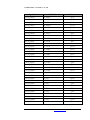
The connections between the FPGA and various clocking resources are documented
in Table 4.
Table 4 – FPGA Clocking
Signal Name
FPGA Pin
Function
CLK_FPGA_OSC_P
U7.AH15
100 MHz from the Oscillator
CLK_FPGA_OSC_N
U7.AJ15
CLK_FPGA_FBOUT
U7.AF15
CLK_FPGA_FBIN_P
U7.B16
CLK_FPGA_FBIN_N
U7.C16
100 MHz from the Oscillator
Output to clock buffer for
system-synchronous operation
Input from system-synchronous
clock buffer
Input from system-synchronous
clock buffer
XHEADER_REFCLK_UP
U7.L4
Output to ARM for use as AHB
hclk input (on selected Core Tiles)
XHEADER_HCLKIN_UP
XHEADER_HCLK_DN
U7.L3
U7.A15
Output to ARM for use as AHB
hclk input (on selected Core Tiles)
Input for clocking AHB interface
ZHEADER_CLK_GLOBAL
U7.B15
Output to ARM for use as AHB
hclk input (on selected Core Tiles)
Retimed clock – see ARM Core
Tile documentation
Retimed clock – see ARM Core
Tile documentation
ZHEADER_CLK_POS_DN_IN
U7.AK16
ZHEADER_CLK_NEG_DN_IN
U7.AJ16
ZHEADER_CLK_POS_UP_OUT
U7.J22
ZHEADER_CLK_NEG_UP_OUT
U7.H22
Retimed clock – see ARM Core
Tile documentation
Retimed clock – see ARM Core
Tile documentation
ZHEADER_CLK_OUT_PLUS1
U7.F22
Delay-matched clock – see ARM
Core Tile documentation
ZHEADER_CLK_OUT_PLUS2
U7.E22
Delay-matched clock – see ARM
Core Tile documentation
ZHEADER_CLK_IN_PLUS1
U7.B16
ZHEADER_CLK_IN_PLUS2
U7.C16
DNMEG_ARM_TILE User Manual
Delay-matched clock – see ARM
Core Tile documentation
Delay-matched clock – see ARM
Core Tile documentation
www.dinigroup.com
24
H A R D W A R E
D E S C R I P T I O N
11.2 Daughter Card Clocks
The 400 pin MEG-Array connector on the bottom of the PCBA is used to interface to
the Dini Group products, e.g. DN7002k10MEG.
11.2.1 Connections between the FPGA and the Daughter Card Header Clocks
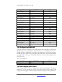
The connections between the FPGA and the Daughter Card Header Clocks are shown
in Table 5.
Table 5 - Connections for Daughter Card Header Clocks
Signal Name
XHEADER_HCLK_DN_2.5V
DC Pin
P1.E1
XHEADER_REFCLK_UP_2.5V P1.F1
CLK_ETHB_RX_2.5V
P1.E3
ZHEADER_CLK_GLOBAL
P1.F3
CLK_FPGA_DC_P
P1.E5
CLK_FPGA_DC_N
P1.F5
XHEADER_HCLKIN_UP
CLK_ETHB_TX
CLK125_ETHB
P1.A37
P1.K37
Function
Input for clocking AHB interface
Output to ARM for use as AHB
hclk input (on selected Core Tiles)
Ethernet clock for receive data
Output to ARM for use as AHB
hclk input (on selected Core Tiles)
Input from system-synchronous
clock buffer
Input from system-synchronous
clock buffer
Output to ARM for use as AHB
hclk input (on selected Core Tiles)
Ethernet clock for transmit data
125 MHz Ethernet reference clock
12 ARM Headers
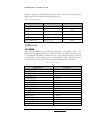
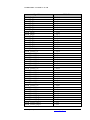
The ARM header (J7, J9, J14) connections were designed to be fully compliant with the
CT926EJ-S featuring an ARM9 processor. For full descriptions of the function of
these signals, please consult the ARM Core Tile documentation.
Table 6 – ARM Header Connections
Signal Name
XHEADER_ARM_PORESET_N
XHEADER_BIGENDOUT
XHEADER_CONFIGINIT
XHEADER_CONFIGRST_N
XHEADER_FIQ_N
XHEADER_HADDR0
XHEADER_HADDR1
DNMEG_ARM_TILE User Manual
FPGA Pin
U7.W4
U7.W7
U7.W6
U7.W3
U7.W9
U7.AA2
U7.AA3
www.dinigroup.com
25
H A R D W A R E
D E S C R I P T I O N
Signal Name
XHEADER_HADDR10
XHEADER_HADDR11
XHEADER_HADDR12
XHEADER_HADDR13
XHEADER_HADDR14
XHEADER_HADDR15
XHEADER_HADDR16
XHEADER_HADDR17
XHEADER_HADDR18
XHEADER_HADDR19
XHEADER_HADDR2
XHEADER_HADDR20
XHEADER_HADDR21
XHEADER_HADDR22
XHEADER_HADDR23
XHEADER_HADDR24
XHEADER_HADDR25
XHEADER_HADDR26
XHEADER_HADDR27
XHEADER_HADDR28
XHEADER_HADDR29
XHEADER_HADDR3
XHEADER_HADDR30
XHEADER_HADDR31
XHEADER_HADDR4
XHEADER_HADDR5
XHEADER_HADDR6
XHEADER_HADDR7
XHEADER_HADDR8
XHEADER_HADDR9
XHEADER_HBURST0
XHEADER_HBURST1
XHEADER_HBURST2
XHEADER_HBUSREQ
XHEADER_HCLKIN_UP
XHEADER_HDATA0
XHEADER_HDATA1
XHEADER_HDATA10
XHEADER_HDATA11
XHEADER_HDATA12
XHEADER_HDATA13
XHEADER_HDATA14
DNMEG_ARM_TILE User Manual
FPGA Pin
U7.T2
U7.Y3
U7.Y4
U7.T7
U7.T8
U7.AB6
U7.J8
U7.K9
U7.K7
U7.K6
U7.Y10
U7.K3
U7.K2
U7.K10
U7.L10
U7.L8
U7.L7
U7.L6
U7.L5
U7.M5
U7.N6
U7.AA10
U7.N5
U7.N4
U7.Y7
U7.Y8
U7.Y5
U7.Y6
U7.T4
U7.T1
U7.V1
U7.V5
U7.V4
U7.V6
U7.L3
U7.AH1
U7.AH2
U7.AE2
U7.AE3
U7.AD3
U7.AD4
U7.AD1
www.dinigroup.com
26
H A R D W A R E
D E S C R I P T I O N
Signal Name
XHEADER_HDATA15
XHEADER_HDATA16
XHEADER_HDATA17
XHEADER_HDATA18
XHEADER_HDATA19
XHEADER_HDATA2
XHEADER_HDATA20
XHEADER_HDATA21
XHEADER_HDATA22
XHEADER_HDATA23
XHEADER_HDATA24
XHEADER_HDATA25
XHEADER_HDATA26
XHEADER_HDATA27
XHEADER_HDATA28
XHEADER_HDATA29
XHEADER_HDATA3
XHEADER_HDATA30
XHEADER_HDATA31
XHEADER_HDATA4
XHEADER_HDATA5
XHEADER_HDATA6
XHEADER_HDATA7
XHEADER_HDATA8
XHEADER_HDATA9
XHEADER_HGRANT
XHEADER_HLOCK
XHEADER_HPROT0
XHEADER_HPROT1
XHEADER_HPROT2
XHEADER_HPROT3
XHEADER_HPROT4
XHEADER_HPROT5
XHEADER_HRDATA0
XHEADER_HRDATA1
XHEADER_HRDATA10
XHEADER_HRDATA11
XHEADER_HRDATA12
XHEADER_HRDATA13
XHEADER_HRDATA14
XHEADER_HRDATA15
XHEADER_HRDATA16
DNMEG_ARM_TILE User Manual
FPGA Pin
U7.AD2
U7.AC7
U7.AD6
U7.AC5
U7.AC6
U7.AG3
U7.AC3
U7.AC4
U7.AC1
U7.AC2
U7.AB4
U7.AB5
U7.AB1
U7.AB2
U7.AA9
U7.AB8
U7.AG4
U7.AA6
U7.AA7
U7.AG1
U7.AG2
U7.AF1
U7.AF2
U7.AE5
U7.AF4
U7.W10
U7.V9
U7.U3
U7.U2
U7.U7
U7.U6
U7.U10
U7.U9
U7.M8
U7.M9
U7.R9
U7.R10
U7.P2
U7.P3
U7.P6
U7.P7
U7.P9
www.dinigroup.com
27
H A R D W A R E
D E S C R I P T I O N
Signal Name
XHEADER_HRDATA17
XHEADER_HRDATA18
XHEADER_HRDATA19
XHEADER_HRDATA2
XHEADER_HRDATA20
XHEADER_HRDATA21
XHEADER_HRDATA22
XHEADER_HRDATA23
XHEADER_HRDATA24
XHEADER_HRDATA25
XHEADER_HRDATA26
XHEADER_HRDATA27
XHEADER_HRDATA28
XHEADER_HRDATA29
XHEADER_HRDATA3
XHEADER_HRDATA30
XHEADER_HRDATA31
XHEADER_HRDATA4
XHEADER_HRDATA5
XHEADER_HRDATA6
XHEADER_HRDATA7
XHEADER_HRDATA8
XHEADER_HRDATA9
XHEADER_HREADY
XHEADER_HRESP0
XHEADER_HRESP1
XHEADER_HRESP2
XHEADER_HSIZE0
XHEADER_HSIZE1
XHEADER_HSIZE2
XHEADER_HTRANS0
XHEADER_HTRANS1
XHEADER_HWRITE
XHEADER_IRQ_N
XHEADER_PLLLOCK
XHEADER_REFCLK_UP
XHEADER_RESET_N
XHEADER_PLLFBDIV0
XHEADER_PLLFBDIV1
XHEADER_PLLFBDIV2
XHEADER_PLLFBDIV3
XHEADER_PLLFBDIV4
DNMEG_ARM_TILE User Manual
FPGA Pin
U7.P10
U7.N1
U7.N2
U7.R1
U7.N8
U7.N9
U7.N10
U7.M10
U7.M1
U7.M2
U7.M3
U7.M4
U7.M6
U7.M7
U7.R2
U7.L1
U7.L2
U7.R3
U7.R4
U7.R5
U7.R6
U7.R7
U7.R8
U7.V8
U7.V10
U7.W2
U7.W1
U7.T5
U7.T10
U7.T9
U7.T3
U7.T6
U7.W5
U7.W8
U7.Y1
U7.L4
U7.Y2
U7.B27
U7.A27
U7.C27
U7.D26
U7.B26
www.dinigroup.com
28
H A R D W A R E
D E S C R I P T I O N
Signal Name
XHEADER_PLLFBDIV5
XHEADER_PLLFBDIV6
XHEADER_PLLFBDIV7
XHEADER_PLLOUTDIV0
XHEADER_PLLOUTDIV1
XHEADER_PLLOUTDIV2
XHEADER_PLLOUTDIV3
XHEADER_PLLREFDIV0
XHEADER_PLLREFDIV1
XHEADER_PLLREFDIV2
XHEADER_PLLREFDIV3
XHEADER_HCLKDIV0
XHEADER_HCLKDIV1
XHEADER_HCLKDIV2
XHEADER_PLLBYPASS
XHEADER_PLLCTRL0
XHEADER_PLLCTRL1
XHEADER_HCLK_DN
YHEADER_MEMEXPA0
YHEADER_MEMEXPA1
YHEADER_MEMEXPA10
YHEADER_MEMEXPA100
YHEADER_MEMEXPA101
YHEADER_MEMEXPA102
YHEADER_MEMEXPA103
YHEADER_MEMEXPA11
YHEADER_MEMEXPA12
YHEADER_MEMEXPA13
YHEADER_MEMEXPA14
YHEADER_MEMEXPA15
YHEADER_MEMEXPA16
YHEADER_MEMEXPA17
YHEADER_MEMEXPA18
YHEADER_MEMEXPA19
YHEADER_MEMEXPA2
YHEADER_MEMEXPA20
YHEADER_MEMEXPA21
YHEADER_MEMEXPA22
YHEADER_MEMEXPA23
YHEADER_MEMEXPA24
YHEADER_MEMEXPA25
YHEADER_MEMEXPA26
DNMEG_ARM_TILE User Manual
FPGA Pin
U7.A26
U7.C25
U7.B25
U7.F25
U7.F24
U7.D24
U7.C24
U7.D23
U7.C23
U7.B23
U7.A23
U7.G24
U7.A24
U7.B24
U7.H23
U7.G23
U7.F23
U7.A15
U7.J29
U7.J30
U7.G25
U7.T22
U7.T23
U7.T24
U7.T25
U7.H24
U7.G29
U7.G30
U7.G27
U7.G28
U7.F28
U7.F29
U7.E29
U7.E30
U7.J26
U7.D29
U7.D30
U7.D27
U7.D28
U7.C29
U7.C30
U7.K22
www.dinigroup.com
29
H A R D W A R E
D E S C R I P T I O N
Signal Name
YHEADER_MEMEXPA27
YHEADER_MEMEXPA28
YHEADER_MEMEXPA29
YHEADER_MEMEXPA3
YHEADER_MEMEXPA30
YHEADER_MEMEXPA31
YHEADER_MEMEXPA32
YHEADER_MEMEXPA33
YHEADER_MEMEXPA34
YHEADER_MEMEXPA35
YHEADER_MEMEXPA36
YHEADER_MEMEXPA37
YHEADER_MEMEXPA38
YHEADER_MEMEXPA39
YHEADER_MEMEXPA4
YHEADER_MEMEXPA40
YHEADER_MEMEXPA41
YHEADER_MEMEXPA42
YHEADER_MEMEXPA43
YHEADER_MEMEXPA44
YHEADER_MEMEXPA45
YHEADER_MEMEXPA46
YHEADER_MEMEXPA47
YHEADER_MEMEXPA48
YHEADER_MEMEXPA49
YHEADER_MEMEXPA5
YHEADER_MEMEXPA50
YHEADER_MEMEXPA51
YHEADER_MEMEXPA52
YHEADER_MEMEXPA53
YHEADER_MEMEXPA54
YHEADER_MEMEXPA55
YHEADER_MEMEXPA56
YHEADER_MEMEXPA57
YHEADER_MEMEXPA58
YHEADER_MEMEXPA59
YHEADER_MEMEXPA6
YHEADER_MEMEXPA60
YHEADER_MEMEXPA61
YHEADER_MEMEXPA62
YHEADER_MEMEXPA63
YHEADER_MEMEXPA64
DNMEG_ARM_TILE User Manual
FPGA Pin
U7.J23
U7.K25
U7.K24
U7.J27
U7.L26
U7.L25
U7.L28
U7.L27
U7.L30
U7.L29
U7.M23
U7.M22
U7.M25
U7.M24
U7.H29
U7.M28
U7.M27
U7.N21
U7.M21
U7.N23
U7.N22
U7.N25
U7.M26
U7.N27
U7.N26
U7.H30
U7.N30
U7.N29
U7.P22
U7.P21
U7.P25
U7.P24
U7.P29
U7.P28
U7.R22
U7.R21
U7.H27
U7.R24
U7.R23
U7.R26
U7.R25
U7.R28
www.dinigroup.com
30
H A R D W A R E
D E S C R I P T I O N
Signal Name
YHEADER_MEMEXPA65
YHEADER_MEMEXPA66
YHEADER_MEMEXPA67
YHEADER_MEMEXPA68
YHEADER_MEMEXPA69
YHEADER_MEMEXPA7
YHEADER_MEMEXPA70
YHEADER_MEMEXPA71
YHEADER_MEMEXPA72
YHEADER_MEMEXPA73
YHEADER_MEMEXPA74
YHEADER_MEMEXPA75
YHEADER_MEMEXPA76
YHEADER_MEMEXPA77
YHEADER_MEMEXPA78
YHEADER_MEMEXPA79
YHEADER_MEMEXPA8
YHEADER_MEMEXPA80
YHEADER_MEMEXPA81
YHEADER_MEMEXPA82
YHEADER_MEMEXPA83
YHEADER_MEMEXPA84
YHEADER_MEMEXPA85
YHEADER_MEMEXPA86
YHEADER_MEMEXPA87
YHEADER_MEMEXPA88
YHEADER_MEMEXPA89
YHEADER_MEMEXPA9
YHEADER_MEMEXPA90
YHEADER_MEMEXPA91
YHEADER_MEMEXPA92
YHEADER_MEMEXPA93
YHEADER_MEMEXPA94
YHEADER_MEMEXPA95
YHEADER_MEMEXPA96
YHEADER_MEMEXPA97
YHEADER_MEMEXPA98
YHEADER_MEMEXPA99
ZHEADER_CFGEN_N
ZHEADER_CLK_GLOBAL
ZHEADER_CLK_NEG_DN_IN
ZHEADER_CLK_NEG_UP_OUT
DNMEG_ARM_TILE User Manual
FPGA Pin
U7.R27
U7.R30
U7.R29
U7.F26
U7.E27
U7.H28
U7.K29
U7.K28
U7.L21
U7.K21
U7.L24
U7.L23
U7.M30
U7.M29
U7.J25
U7.Y27
U7.H25
U7.Y28
U7.Y29
U7.Y30
U7.W29
U7.W30
U7.W21
U7.V21
U7.V22
U7.V23
U7.W26
U7.H26
U7.V25
U7.V29
U7.V30
U7.U21
U7.U22
U7.U24
U7.U25
U7.U28
U7.U29
U7.T21
U7.J17
U7.B15
U7.AJ16
U7.H22
www.dinigroup.com
31
H A R D W A R E
D E S C R I P T I O N
Signal Name
ZHEADER_CLK_OUT_PLUS1
ZHEADER_CLK_OUT_PLUS2
ZHEADER_CLK_POS_DN_IN
ZHEADER_CLK_POS_UP_OUT
ZHEADER_CLK_UP_THRU
ZHEADER_FPGA_IMAGE
ZHEADER_GLOBAL_DONE
ZHEADER_MEMEXPB0
ZHEADER_MEMEXPB1
ZHEADER_MEMEXPB10
ZHEADER_MEMEXPB100
ZHEADER_MEMEXPB101
ZHEADER_MEMEXPB102
ZHEADER_MEMEXPB103
ZHEADER_MEMEXPB11
ZHEADER_MEMEXPB12
ZHEADER_MEMEXPB13
ZHEADER_MEMEXPB14
ZHEADER_MEMEXPB15
ZHEADER_MEMEXPB16
ZHEADER_MEMEXPB17
ZHEADER_MEMEXPB18
ZHEADER_MEMEXPB19
ZHEADER_MEMEXPB2
ZHEADER_MEMEXPB20
ZHEADER_MEMEXPB21
ZHEADER_MEMEXPB22
ZHEADER_MEMEXPB23
ZHEADER_MEMEXPB24
ZHEADER_MEMEXPB25
ZHEADER_MEMEXPB26
ZHEADER_MEMEXPB27
ZHEADER_MEMEXPB28
ZHEADER_MEMEXPB29
ZHEADER_MEMEXPB3
ZHEADER_MEMEXPB30
ZHEADER_MEMEXPB31
ZHEADER_MEMEXPB32
ZHEADER_MEMEXPB33
ZHEADER_MEMEXPB34
ZHEADER_MEMEXPB35
ZHEADER_MEMEXPB36
DNMEG_ARM_TILE User Manual
FPGA Pin
U7.F22
U7.E22
U7.AK16
U7.J22
U7.E23
U7.K20
U7.J21
U7.A4
U7.B4
U7.C7
U7.H18
U7.E18
U7.D18
U7.B18
U7.D7
U7.E8
U7.F8
U7.C8
U7.D8
U7.A8
U7.B8
U7.H9
U7.J9
U7.A5
U7.F10
U7.G10
U7.B10
U7.C10
U7.K11
U7.J10
U7.G11
U7.H11
U7.E11
U7.F11
U7.B5
U7.C11
U7.D11
U7.A11
U7.B11
U7.J12
U7.K12
U7.G12
www.dinigroup.com
32
H A R D W A R E
D E S C R I P T I O N
Signal Name
ZHEADER_MEMEXPB37
ZHEADER_MEMEXPB38
ZHEADER_MEMEXPB39
ZHEADER_MEMEXPB4
ZHEADER_MEMEXPB40
ZHEADER_MEMEXPB41
ZHEADER_MEMEXPB42
ZHEADER_MEMEXPB43
ZHEADER_MEMEXPB44
ZHEADER_MEMEXPB45
ZHEADER_MEMEXPB46
ZHEADER_MEMEXPB47
ZHEADER_MEMEXPB48
ZHEADER_MEMEXPB49
ZHEADER_MEMEXPB5
ZHEADER_MEMEXPB50
ZHEADER_MEMEXPB51
ZHEADER_MEMEXPB52
ZHEADER_MEMEXPB53
ZHEADER_MEMEXPB54
ZHEADER_MEMEXPB55
ZHEADER_MEMEXPB56
ZHEADER_MEMEXPB57
ZHEADER_MEMEXPB58
ZHEADER_MEMEXPB59
ZHEADER_MEMEXPB6
ZHEADER_MEMEXPB60
ZHEADER_MEMEXPB61
ZHEADER_MEMEXPB62
ZHEADER_MEMEXPB63
ZHEADER_MEMEXPB64
ZHEADER_MEMEXPB65
ZHEADER_MEMEXPB66
ZHEADER_MEMEXPB67
ZHEADER_MEMEXPB68
ZHEADER_MEMEXPB69
ZHEADER_MEMEXPB7
ZHEADER_MEMEXPB70
ZHEADER_MEMEXPB71
ZHEADER_MEMEXPB72
ZHEADER_MEMEXPB73
ZHEADER_MEMEXPB74
DNMEG_ARM_TILE User Manual
FPGA Pin
U7.H12
U7.E12
U7.F12
U7.E6
U7.C12
U7.D12
U7.A12
U7.B12
U7.H13
U7.J13
U7.E13
U7.F13
U7.A13
U7.B13
U7.D5
U7.J14
U7.K14
U7.F14
U7.G14
U7.B14
U7.C14
U7.H15
U7.J15
U7.F15
U7.G15
U7.B6
U7.C15
U7.D15
U7.A7
U7.B7
U7.H8
U7.G7
U7.D9
U7.E9
U7.A9
U7.B9
U7.C6
U7.C4
U7.D13
U7.E15
U7.F9
U7.G8
www.dinigroup.com
33
H A R D W A R E
D E S C R I P T I O N
Signal Name
ZHEADER_MEMEXPB75
ZHEADER_MEMEXPB76
ZHEADER_MEMEXPB77
ZHEADER_MEMEXPB78
ZHEADER_MEMEXPB79
ZHEADER_MEMEXPB8
ZHEADER_MEMEXPB80
ZHEADER_MEMEXPB81
ZHEADER_MEMEXPB82
ZHEADER_MEMEXPB83
ZHEADER_MEMEXPB84
ZHEADER_MEMEXPB85
ZHEADER_MEMEXPB86
ZHEADER_MEMEXPB87
ZHEADER_MEMEXPB88
ZHEADER_MEMEXPB89
ZHEADER_MEMEXPB9
ZHEADER_MEMEXPB90
ZHEADER_MEMEXPB91
ZHEADER_MEMEXPB92
ZHEADER_MEMEXPB93
ZHEADER_MEMEXPB94
ZHEADER_MEMEXPB95
ZHEADER_MEMEXPB96
ZHEADER_MEMEXPB97
ZHEADER_MEMEXPB98
ZHEADER_MEMEXPB99
ZHEADER_RTCKEN_N
ZHEADER_SPARE0
ZHEADER_SPARE1
ZHEADER_SPARE10
ZHEADER_SPARE11
ZHEADER_SPARE12
ZHEADER_SPARE2
ZHEADER_SPARE3
ZHEADER_SPARE4
ZHEADER_SPARE5
ZHEADER_SPARE6
ZHEADER_SPARE7
ZHEADER_SPARE8
ZHEADER_SPARE9
ZHEADER_SYSPOR_N
DNMEG_ARM_TILE User Manual
FPGA Pin
U7.K13
U7.K15
U7.B20
U7.A20
U7.K19
U7.F7
U7.J19
U7.H19
U7.G19
U7.F19
U7.E19
U7.D19
U7.C19
U7.B19
U7.A19
U7.G17
U7.F6
U7.F17
U7.C17
U7.B17
U7.K16
U7.J16
U7.H16
U7.G16
U7.E16
U7.D16
U7.J18
U7.F16
U7.D22
U7.B22
U7.E20
U7.D20
U7.C20
U7.A22
U7.G21
U7.F21
U7.C21
U7.B21
U7.H20
U7.G20
U7.F20
U7.A16
www.dinigroup.com
34
H A R D W A R E
D E S C R I P T I O N
Signal Name
ZHEADER_SYSRST_N
FPGA Pin
U7.E25
In addition, several static signals are attached to DIP Switches S1 and S2. When the
switches are in the OFF position, the signals will be HIGH. Turning the switches ON
results in making the signals LOW.
Table 7 – Signals on S1 and S2
Signal Name
XHEADER_BIGENDIN
XHEADER_INITRAM
XHEADER_VINITHI
XHEADER_DBGEN
XHEADER_TESTSELECT
XHEADER_TICSELECT
Pin
S2.1
S2.2
S2.3
S2.4
S1.1
S1.2
13 General Purpose Headers
The FPGA_LED and FPGA_GPIO busses serve as general purpose communication,
the FPGA_LED bus having the added bonus of being connected to LEDs. These
busses are connected to the Spartan FPGA, the ARM Z Header, and surface mount
headers for external interfacing.
Table 8 – General Purpose Headers
Signal Name
FPGA Pin
Header
FPGA_LED0
U7.AH29
J17.1
FPGA_LED1
U7.AH30
J17.3
FPGA_LED2
FPGA_LED3
U7.AG27
U7.AG28
J17.5
J17.7
FPGA_LED4
U7.AG29
J17.9
FPGA_LED5
FPGA_LED6
U7.AG30
U7.AF29
J17.11
J17.13
FPGA_LED7
U7.AF30
J17.15
FPGA_LED8
FPGA_LED9
U7.AF27
U7.AE26
J17.17
J17.2
FPGA_LED10
U7.AE28
J17.4
FPGA_LED11
U7.AE29
J17.6
DNMEG_ARM_TILE User Manual
www.dinigroup.com
35
H A R D W A R E
D E S C R I P T I O N
Signal Name
FPGA Pin
Header
FPGA_LED12
U7.AD27
J17.8
FPGA_LED13
FPGA_LED14
U7.AD28
U7.AD29
J17.10
J17.12
FPGA_LED15
U7.AD30
J17.14
FPGA_LED16
FPGA_LED17
U7.AD25
U7.AC24
J17.16
J17.18
FPGA_LED18
U7.AC25
J18.1
FPGA_LED19
U7.AC26
J18.3
FPGA_LED20
U7.AC27
J18.5
FPGA_LED21
FPGA_LED22
U7.AC28
U7.AC29
J18.7
J18.9
FPGA_LED23
U7.AC30
J18.11
FPGA_LED24
U7.AB26
J18.13
FPGA_LED25
U7.AB27
J18.15
FPGA_LED26
U7.AB29
J18.17
FPGA_LED27
FPGA_LED28
U7.AB30
U7.AB23
J18.2
J18.4
FPGA_LED29
U7.AA22
J18.6
FPGA_LED30
U7.AA24
J18.8
FPGA_LED31
U7.AA25
J18.10
FPGA_GPIO0
U7.AA28
J18.12
FPGA_GPIO1
FPGA_GPIO2
U7.AA29
U7.AA21
J18.14
J18.16
FPGA_GPIO3
U7.Y21
J18.18
FPGA_GPIO4
FPGA_GPIO5
U7.Y23
U7.Y23
J21.1
J21.3
FPGA_GPIO6
U7.Y25
J21.5
FPGA_GPIO7
FPGA_GPIO8
U7.Y26
U7.T26
J21.7
J21.9
FPGA_GPIO9
U7.T27
J21.11
FPGA_GPIO10
U7.T28
J21.13
FPGA_GPIO11
U7.T29
J21.15
FPGA_GPIO12
U7.T30
J21.2
DNMEG_ARM_TILE User Manual
www.dinigroup.com
36
H A R D W A R E
D E S C R I P T I O N
Signal Name
FPGA Pin
Header
FPGA_GPIO13
U7.W22
J21.4
FPGA_GPIO14
FPGA_GPIO15
U7.W23
U7.W24
J21.6
J21.8
FPGA_GPIO16
U7.W25
J21.10
FPGA_GPIO17
FPGA_GPIO18
U7.W27
U7.W28
J21.12
J21.14
FPGA_GPIO19
U7.V26
J21.16
FPGA_GPIO20
U7.V27
J21.17
FPGA_GPIO21
U7.AB25
J21.18
14 LED Indicators
The DNMEG_ARM_TILE (REV2) provides various LED’s to indicate that status of
the board.
14.1 User LED’s
32 green LED’s are provided to the user as a design aid during debugging. The LED’s
can be turned ON by driving the corresponding pin LOW. Table 9 describes the user
LED’s and their associated pin assignments on the FPGA (U7).
Table 9 – User LED’s
Signal Name
FPGA_LED0
FPGA Pin
U7.AH29
LED
DS10
FPGA_LED1
U7.AH30
DS12
FPGA_LED2
FPGA_LED3
U7.AG27
U7.AG28
DS14
DS16
FPGA_LED4
U7.AG29
DS18
FPGA_LED5
U7.AG30
DS20
FPGA_LED6
U7.AF29
DS22
FPGA_LED7
U7.AF30
DS24
FPGA_LED8
FPGA_LED9
U7.AF27
U7.AE26
DS26
DS28
FPGA_LED10
U7.AE28
DS30
FPGA_LED11
FPGA_LED12
U7.AE29
U7.AD27
DS32
DS34
DNMEG_ARM_TILE User Manual
www.dinigroup.com
37
H A R D W A R E
D E S C R I P T I O N
Signal Name
FPGA Pin
LED
FPGA_LED13
U7.AD28
DS36
FPGA_LED14
FPGA_LED15
U7.AD29
U7.AD30
DS38
DS40
FPGA_LED16
U7.AD25
DS42
FPGA_LED17
FPGA_LED18
U7.AC24
U7.AC25
DS44
DS46
FPGA_LED19
U7.AC26
DS29
FPGA_LED20
U7.AC27
DS31
FPGA_LED21
U7.AC28
DS33
FPGA_LED22
FPGA_LED23
U7.AC29
U7.AC30
DS35
DS37
FPGA_LED24
U7.AB26
DS39
FPGA_LED25
U7.AB27
DS41
FPGA_LED26
U7.AB29
DS43
FPGA_LED27
U7.AB30
DS45
FPGA_LED28
FPGA_LED29
U7.AB23
U7.AA22
DS21
DS23
FPGA_LED30
U7.AA24
DS25
FPGA_LED31
U7.AA25
DS27
14.2 Configuration DONE LED
After the FPGA has received all the configuration data successfully, it releases the
DONE pin, which is pulled high by a pull-up resistor. A low-to-high transition on the
DONE indicates configuration is complete and initialization of the device can begin.
DONE pin drives a NFET and turns ON the blue LED (DS17) when the DONE pin
goes high. Table 10 describes the DONE LED and its associated pin assignment on
the FPGA (U21).
Table 10 – FPGA_DONE LED
Signal Name
FPGA_DONE
FPGA Pin
U7.AJ28
LED
DS7
14.3 Power Supply Status LED’s
LED’s are provided to indicate the presence of various power supplies. The power
monitors (U15, U16) monitor the P12VD, P3.3VD, P3.0VD, P2.5VD, and P1.2VD
voltage levels and signals an under-voltage condition by pulling “FPGA_PROG_N”
DNMEG_ARM_TILE User Manual
www.dinigroup.com
38
H A R D W A R E
D E S C R I P T I O N
signal low. The status of this signal is indicated by DS19. Table 11 describes the power
supply status LED’s and their associated voltage source.
Table 11 – Power Supply Status LED’s
Signal Name
P12VD
P5VD
P3.3VD
P2.5VD
PVDDIO
FPGA_PROG_N
Source
LED
DS4
DS3
DS2
DS6
DS5
DS19
J5.1
J5.4
PSU5.6
PSU2.6
J4.2 (PSU1.6 or PSU3.6)
U15.4, U16.4
15 Memory
15.1 SRAM
The 32-bit wide SRAM has the following connections to the Spartan FPGA. The
SRAM shares its address and data bus with the FLASH – this requires that transactions
to the SRAM and FLASH be mutually exclusive. Some address bits may not be used
on the SRAM – check stuffing options for actual address width. Signal descriptions
and functionality can be found in the datasheet distributed with this document.
Table 12 – SRAM Connections
Signal Name
SRAM_ADSC_N
SRAM_ADSP_N
SRAM_ADV_N
SRAM_BWA_N
SRAM_BWB_N
SRAM_BWC_N
SRAM_BWD_N
SRAM_BWE_N
SRAM_CE1_N
SRAM_CE2
SRAM_CE3_N
SRAM_CLK
SRAM_DQ16
SRAM_DQ17
SRAM_DQ18
SRAM_DQ19
SRAM_DQ20
FPGA Pin
U7.AD15
U7.AE15
U7.AE6
U7.AH8
U7.AA11
U7.AA15
U7.AB10
U7.AG8
U7.AG15
U7.AC8
U7.AD8
U7.AJ7
U7.AK12
U7.AA12
U7.AA13
U7.AB13
U7.AC13
DNMEG_ARM_TILE User Manual
www.dinigroup.com
39
H A R D W A R E
D E S C R I P T I O N
Signal Name
SRAM_DQ21
SRAM_DQ22
SRAM_DQ23
SRAM_DQ24
SRAM_DQ25
SRAM_DQ26
SRAM_DQ27
SRAM_DQ28
SRAM_DQ29
SRAM_DQ30
SRAM_DQ31
SRAM_DQP0
SRAM_DQP1
SRAM_DQP2
SRAM_DQP3
SRAM_FLASH_A0
SRAM_FLASH_A1
SRAM_FLASH_A10
SRAM_FLASH_A11
SRAM_FLASH_A12
SRAM_FLASH_A13
SRAM_FLASH_A14
SRAM_FLASH_A15
SRAM_FLASH_A16
SRAM_FLASH_A17
SRAM_FLASH_A18
SRAM_FLASH_A19
SRAM_FLASH_A2
SRAM_FLASH_A20
SRAM_FLASH_A21
SRAM_FLASH_A3
SRAM_FLASH_A4
SRAM_FLASH_A5
SRAM_FLASH_A6
SRAM_FLASH_A7
SRAM_FLASH_A8
SRAM_FLASH_A9
SRAM_FLASH_DQ0
SRAM_FLASH_DQ1
SRAM_FLASH_DQ10
SRAM_FLASH_DQ11
SRAM_FLASH_DQ12
FPGA Pin
U7.AF13
U7.AG13
U7.AJ13
U7.AA14
U7.AB14
U7.AE13
U7.AE14
U7.AH14
U7.AJ14
U7.AB15
U7.AC15
U7.AJ5
U7.AH7
U7.AJ12
U7.AK13
U7.AE9
U7.AE10
U7.AJ11
U7.AK11
U7.AC11
U7.AB12
U7.AC12
U7.AD12
U7.AE12
U7.AF12
U7.AG12
U7.AH12
U7.AH10
U7.AH4
U7.AK15
U7.AJ10
U7.AD10
U7.AD11
U7.AE11
U7.AF11
U7.AG11
U7.AH11
U7.AK5
U7.AG5
U7.AB9
U7.AC9
U7.AF9
DNMEG_ARM_TILE User Manual
www.dinigroup.com
40
H A R D W A R E
D E S C R I P T I O N
Signal Name
SRAM_FLASH_DQ13
SRAM_FLASH_DQ14
SRAM_FLASH_DQ15
SRAM_FLASH_DQ2
SRAM_FLASH_DQ3
SRAM_FLASH_DQ4
SRAM_FLASH_DQ5
SRAM_FLASH_DQ6
SRAM_FLASH_DQ7
SRAM_FLASH_DQ8
SRAM_FLASH_DQ9
SRAM_MODE
SRAM_OE_N
SRAM_WE_N
SRAM_ZZ
FPGA Pin
U7.AG9
U7.AJ9
U7.AK9
U7.AF6
U7.AH6
U7.AJ6
U7.AD7
U7.AE7
U7.AG7
U7.AJ8
U7.AK8
U7.AD14
U7.AE8
U7.AF8
U7.AD16
15.2 DRAM
The DNMEG_ARM_TILE (REV2) uses two 16-bit wide DRAM chips in parallel to
create a 32-bit wide DRAM interface. The connections to the DRAM are listed below.
Some address bits may not be used on the DRAM – check stuffing options for actual
address width. Signal descriptions and functionality can be found in the datasheet
distributed with this document.
Table 13 – DRAM Connections
Signal Name
FPGA Pin
DRAM_A0
DRAM_A1
DRAM_A10
DRAM_A11
DRAM_A12
DRAM_A2
DRAM_A3
DRAM_A4
DRAM_A5
DRAM_A6
DRAM_A7
DRAM_A8
DRAM_A9
DRAM_BA0
DRAM_BA1
U7.AK27
U7.AJ27
U7.AH23
U7.AG23
U7.AK23
U7.AK26
U7.AJ26
U7.AF25
U7.AG26
U7.AC23
U7.AD24
U7.AF23
U7.AE23
U7.AJ23
U7.AC22
DNMEG_ARM_TILE User Manual
www.dinigroup.com
41
H A R D W A R E
D E S C R I P T I O N
Signal Name
DRAM_CAS_N
DRAM_CKE
DRAM_CLK0
DRAM_CLK1
DRAM_CS_N
DRAM_DQ0
DRAM_DQ1
DRAM_DQ10
DRAM_DQ11
DRAM_DQ12
DRAM_DQ13
DRAM_DQ14
DRAM_DQ15
DRAM_DQ16
DRAM_DQ17
DRAM_DQ18
DRAM_DQ19
DRAM_DQ2
DRAM_DQ20
DRAM_DQ21
DRAM_DQ22
DRAM_DQ23
DRAM_DQ24
DRAM_DQ25
DRAM_DQ26
DRAM_DQ27
DRAM_DQ28
DRAM_DQ29
DRAM_DQ3
DRAM_DQ30
DRAM_DQ31
DRAM_DQ4
DRAM_DQ5
DRAM_DQ6
DRAM_DQ7
DRAM_DQ8
DRAM_DQ9
DRAM_DQM0
DRAM_DQM1
DRAM_DQM2
DRAM_DQM3
DRAM_RAS_N
FPGA Pin
U7.AA19
U7.AG20
U7.AK20
U7.AJ20
U7.AC19
U7.AB22
U7.AG22
U7.AB21
U7.AD20
U7.AC20
U7.AF20
U7.AE20
U7.AH20
U7.AK19
U7.AJ19
U7.AC18
U7.AB18
U7.AF22
U7.AF18
U7.AE18
U7.AK18
U7.AJ18
U7.AB17
U7.AA17
U7.AE17
U7.AJ17
U7.AH17
U7.AC16
U7.AK22
U7.AB16
U7.AE16
U7.AJ22
U7.AE21
U7.AD21
U7.AJ21
U7.AH21
U7.AA20
U7.AF19
U7.AE19
U7.AH19
U7.AG19
U7.AD19
DNMEG_ARM_TILE User Manual
www.dinigroup.com
42
H A R D W A R E
D E S C R I P T I O N
Signal Name
DRAM_WE_N
FPGA Pin
U7.AB19
15.3 FLASH
The FLASH w/ 16-bit wide data has the following connections to the Spartan FPGA.
The FLASH can be given a 32-bit wide interface in RTL, requiring multiple
reads/writes per transaction. The FLASH shares its address and data bus with the
SRAM – this requires that transactions to the SRAM and FLASH be mutually
exclusive. Some address bits may not be used on the FLASH – check stuffing options
for actual address width. Signal descriptions and functionality can be found in the
datasheet distributed with this document.
Table 14 – FLASH Connections
Signal Name
FLASH_CE_N
FLASH_OE_N
FLASH_RESET_N
FLASH_WE_N
FLASH_WP_N
SRAM_FLASH_A0
SRAM_FLASH_A1
SRAM_FLASH_A10
SRAM_FLASH_A11
SRAM_FLASH_A12
SRAM_FLASH_A13
SRAM_FLASH_A14
SRAM_FLASH_A15
SRAM_FLASH_A16
SRAM_FLASH_A17
SRAM_FLASH_A18
SRAM_FLASH_A19
SRAM_FLASH_A2
SRAM_FLASH_A20
SRAM_FLASH_A21
SRAM_FLASH_A3
SRAM_FLASH_A4
SRAM_FLASH_A5
SRAM_FLASH_A6
SRAM_FLASH_A7
SRAM_FLASH_A8
SRAM_FLASH_A9
FPGA Pin
U7.AJ25
U7.AH25
U7.AH24
U7.AE24
U7.AE25
U7.AE9
U7.AE10
U7.AJ11
U7.AK11
U7.AC11
U7.AB12
U7.AC12
U7.AD12
U7.AE12
U7.AF12
U7.AG12
U7.AH12
U7.AH10
U7.AH4
U7.AK15
U7.AJ10
U7.AD10
U7.AD11
U7.AE11
U7.AF11
U7.AG11
U7.AH11
DNMEG_ARM_TILE User Manual
www.dinigroup.com
43
H A R D W A R E
D E S C R I P T I O N
Signal Name
SRAM_FLASH_DQ0
SRAM_FLASH_DQ1
SRAM_FLASH_DQ10
SRAM_FLASH_DQ11
SRAM_FLASH_DQ12
SRAM_FLASH_DQ13
SRAM_FLASH_DQ14
SRAM_FLASH_DQ15
SRAM_FLASH_DQ2
SRAM_FLASH_DQ3
SRAM_FLASH_DQ4
SRAM_FLASH_DQ5
SRAM_FLASH_DQ6
SRAM_FLASH_DQ7
SRAM_FLASH_DQ8
SRAM_FLASH_DQ9
FPGA Pin
U7.AK5
U7.AG5
U7.AB9
U7.AC9
U7.AF9
U7.AG9
U7.AJ9
U7.AK9
U7.AF6
U7.AH6
U7.AJ6
U7.AD7
U7.AE7
U7.AG7
U7.AJ8
U7.AK8
16 PS/2 Keyboard and Mouse
The PS/2 interface consists of a bidirectional clock and a single bidirectional data
signal. Please see the Schematic Errata for the actual circuit used in production. The
signal connections are listed below.
Table 15 – PS/2 Connections
Signal Name
KEYBOARD_CK
KEYBOARD_TX
MOUSE_CK
MOUSE_TX
FPGA Pin
U7.AG24
U7.AK24
U7.AA16
U7.AA18
17 AC97
The on-board AC97 SoundMAX® Codec has two 3.5mm audio jacks (J29 and J30)
for input/output to the chip. There are also multiple testpoints that can be connected
manually by the user to an external source for inputs/outputs to the chip other than
those provided. Please consult the AC97 specification for a complete description of
the functionality of the codec.
Table 16 – AC97 Connections
Signal Name
DNMEG_ARM_TILE User Manual
Pin
www.dinigroup.com
44
H A R D W A R E
D E S C R I P T I O N
Signal Name
AUDIO_BIT_CLK
AUDIO_RESET
AUDIO_SDATA_IN
AUDIO_SDATA_OUT
AUDIO_SYNC
LINE_OUT_R
LINE_OUT_L
MIC_IN
Pin
U7.AE22
U7.AK28
U7.AF16
U7.AG18
U7.AH27
J30.3
J30.2
J29.2
In addition, several static signals are attached to DIP Switch S3. When the switches are
in the OFF position, the signals will be HIGH. Turning the switches ON results in
making the signals LOW.
Table 17 – Signals on S3
Signal Name
AUDIO_MODE
AUDIO_CS0
AUDIO_CS1
AUDIO_EAPD
Pin
S3.8
S3.7
S3.6
S3.5
18 RS232 Port
An RS232 serial port is provided for low speed communication with the application on
the FPGA. The RS-232 standard specifies output voltage levels between –5V to –15V
for logical 1 and +5V to +15V for logical 0. Input must be compatible with voltages in
the range of -3V to -15V for logical 1 and +3V to +15V for logical 0. This ensures data
bits are read correctly even at maximum cable lengths between DTE and DCE,
specified as 50 feet.
The connections between the FPGA and the RS232 Port are shown below
Table 18 - Connections between FPGA and the RS232 Port
Signal Name
FPGA_RXD
FPGA_TXD
RS232_EN_N
FPGA Pin
U7.K17
U7.K18
U7.A18
DNMEG_ARM_TILE User Manual
www.dinigroup.com
45
H A R D W A R E
D E S C R I P T I O N
19 JTAG
There are several JTAG connections on the DNMEG_ARM_TILE (REV2). The first
of these connections, the Xilinx JTAG Header J16, allows for programming the
Spartan 3 FPGA and the Xilinx PROM on the DNMEG_ARM_TILE (REV2).
Figure 4 – Xilinx JTAG Connector
P2.5VD
C142
0.1uF
FPGA JTAG
(Cable IV)
P2.5VD
R223
1K
J16
1
3
5
7
9
11
13
GND
GND
GND
GND
GND
GND
GND
VCC
TMS
TCK
TDO
TDI
NC
NC
R222
1K
R226
1K
R229
1K
2
4
6
8
10
12
14
JTAG_TMS
JTAG_TCK
JTAG_TDO
JTAG_TDI
87832-1420 2mm
J10 is the JTAG connector on the board for connecting an ARM debugger/emulator
to the ARM Core Tile.
Note: for J10 to be active, the signal
ZHEADER_CFG_EN_N attached to the Spartan FPGA must be held HIGH.
Figure 5 – Multi-ICE JTAG Connector
Silkscreen:
ICE DEBUG JTAG
J10
20
18
16
14
12
10
8
6
4
2
GND
NC
GND
NC
GND SRSTN
GND
TDO
GND
RTCK
GND
TCK
GND
TMS
GND
TDI
GND TRSTN
VCC
VCC
19
17
15
13
11
9
7
5
3
1
P3.3VD
JTAG_DEBUG_SRSTN
JTAG_DEBUG_TDO
JTAG_DEBUG_RTCK
JTAG_DEBUG_TCK
JTAG_DEBUG_TMS
JTAG_DEBUG_TDI
JTAG_DEBUG_TRSTN
R150
R153
1K
1K
R156
R158
R159
R160
1K
1K
1K
1K
P3.3VD
JTAG_CONN_ICE
TSS-110-01-T-D
C357
0.1uF
C358
0.1uF
For connector spec, see multi-ice user guide F.1
The final two JTAG connectors, J12 and J13, are for reconfiguring devices on the
ARM Core Tile. Both Xilinx- and Multi-ICE-style connectors are provided for this
function, since there are both Xilinx and non-Xilinx parts in the JTAG chain on the
Arm Core Tile.
Note: for J12 and J13 to be active, the signal
ZHEADER_CFG_EN_N attached to the Spartan FPGA must be held LOW.
DNMEG_ARM_TILE User Manual
www.dinigroup.com
46
H A R D W A R E
D E S C R I P T I O N
More detail about the JTAG chains on the ARM Core Tile can be found in the
documentation provided with the Core Tile.
20 Daughter Card Headers
The DNMEG_ARM_TILE (REV2) has one 400-pin MEG-Array daughter card
header (P1). All signals on the DNMEG_ARM_TILE (REV2) Daughter Card
Headers are all routed as differential, 50-Ohm transmission lines. No length-matching
is done on the PCB for Daughter Card signals, (except within a differential pair)
because the Virtex-5 is capable of variable-delay input using the built-in Input/Output
Delay Element (IODELAY) capabilities. Other connections on the daughter card
connector system include three dedicated, differential clock connections for inputting
global clocks from an external source, power connections, bank VCCO power, and a
reset signal.
20.1 Daughter Card clocking
Refer to the Clocking Chapter in this User Manual.
20.2 Daughter Card Header Pin Assignments
The pin assignments of the DNMEG_ARM_TILE (REV2) Daughter Card Headers
were designed to reduce cross talk to manageable levels while operating at full speed of
the Virtex-5 LVDS standards. The Daughter Card Header is divided into three banks,
refer to the following figure.
DNMEG_ARM_TILE User Manual
www.dinigroup.com
47
H A R D W A R E
D E S C R I P T I O N
A B C D E F G H J K
1
2
3
4
5
6
7
8
9
10
11
12
13
14
15
16
17
18
19
20
21
22
+12V
+5V
+3.3V
B0
L1P
B0
L2P
B0
L5P
B0
L10P
B0
L13P
B0
L14P
B0
L17P
B0
L26P
B0
L25N
B1
L3P
B1
L7P
B1
L11P
B1
L11N
23
24
25
26
27
28
29
30
31
32
33
34
35
36
37
38
39
40
B1
L19P
B1
L15N
B1
L19N
B2
L1N
VCCO
2
B2
L5N
B2
L9P
B2
L9N
B2
L13N
B2
L17N
B2
L21N
B2
L27P
B2
L27N
B2
L22N
B1
L21P
B2
L28P
B2
L28N
B2
L29P
B2
L29N
B2
L30P
B2
L30N
B2
L31P
B2
L31N
B1
L22P
25
26
27
28
29
30
31
32
33
34
35
36
37
38
39
40
B1
L26P
B1
L26N
B2
L3P
B2
L4P
B2
L4N
B2
L7P
B2
L7N
B2
L8P
B2
L8N
B2
L11P
B2
L11N
VCCO
2
B2
L12P
B2
L12N
B2
L15P
B2
L15N
B2
L16P
B2
L16N
B2
L19P
B2
L19N
B2
L20P
B2
L20N
B2
L23P
B2
L23N
23
24
B1
L22N
B1
L25P
1
2
3
4
5
6
7
8
9
10
11
12
13
14
15
16
17
18
19
20
21
22
B1
L18P
B1
L18N
B2
L3N
B2
L18N
B2
L22P
B1
L14N
B1
L25N
B2
L14N
B2
L18P
B2
L21P
B2
L26N
B2
L10N
B2
L14P
B2
L17P
B2
L26P
B2
L6N
B2
L10P
B2
L13P
B2
L25N
VCCO
1
B1
L14P
B1
L17P
B1
L21N
B2
L2N
B2
L6P
B1
L13P
B1
L31N
B2
L25P
B1
L10P
B1
L10N
B1
L17N
B1
L24N
B2
L2P
B1
L9P
B1
L13N
B1
L20N
B1
L23N
B2
L5P
B1
L30N
B1
L31P
B1
L24P
B2
L1P
B1
L30P
B1
L16N
B1
L20P
B1
L23P
B1
L29N
B1
L6P
B1
L6N
B1
L9N
B1
L12N
B1
L16P
B1
L5P
B1
L28N
B1
L29P
B1
L2P
B1
L2N
B1
L5N
B1
L28P
B1
L12P
B1
L1P
B1
L27N
B1
L8N
B0
L24P
B0
L24N
B1
L1N
B1
L27P
B1
L8P
B1
L7N
B0
L23P
B0
L31N
B1
L4N
B0
L20P
B0
L20N
B0
L23N
B0
L31P
B1
L4P
B0
L19P
B0
L30N
B0
L26N
B1
L3N
B1
L15P
B0
L30P
B0
L16P
B0
L16N
B0
L19N
B0
L22N
B0
L12P
B0
L15P
B0
L29N
VCCO
0
B0
L12N
B0
L15N
B0
L29P
B0
L22P
B0
L21N
B0
L11P
B0
L28N
B0
L18N
B0
L8P
B0
L8N
B0
L11N
B0
L28P
B0
L18P
B0
L25P
B0
L27N
B0
L14N
B0
L17N
B0
L21P
B0
L7N
B0
L27P
B0
L4P
B0
L4N
B0
L7P
GCCN
B0
L10N
B0
L13N
RSTn
B0
L3N
GCCP
+12V
B0
L3P
GCBN
B0
L6N
B0
L9N
VCCO
1
GCBP
B0
L6P
B0
L9P
+3.3V
B0
L2N
B0
L5N
+5V
GCAN
+3.3V
B0
L1N
VCCO
0
GCAP
B2
L24P
B2
L24N
A B C D E F G H J K
Figure 6 - Daughter Card Header Pin Assignments
DNMEG_ARM_TILE User Manual
www.dinigroup.com
48
H A R D W A R E
D E S C R I P T I O N
20.3 FPGA to Daughter Card Header IO Connections
Most connections to the Daughter Card Header come from the ARM X Header,
which carries the signals for the AHB bus. The intention in the design was to provide
direct access to the ARM Core Tile from a host board (not needing to route through
an intermediary FPGA). While this is completely achieved, the Spartan is still necessary
to drive some setup signals for correct ARM execution. The Ethernet connection on
the DNMEG_ARM_TILE (REV2) is only available if the host board is connected –
these signals are routed directly to the Meg-Array connector.
Table 19 - Daughter Card Header IO Connections
DC SIGNAL
SIGNAL
DC_B0L17N_CC
DC_B0L17P_CC
DC_B0L18N
DC_B0L18P
DC_B0L19N
DC_B0L19P
DC_B0L20N_CC
DC_B0L20P_CC
DC_B0L21N
DC_B0L21P
DC_B0L22N
DC_B0L22P
DC_B0L23N
DC_B0L23P
DC_B0L24N
DC_B0L24P
DC_B0L25N
DC_B0L25P
DC_B0L26N
DC_B0L26P
DC_B0L31N
DC_B0L31P
DC_B1L10N_VREF
DC_B1L10P
DC_B1L12N
DC_B1L12P
DC_B1L13N
DC_B1L13P
DC_B1L14N_VREF
DC_B1L14P
XHEADER_HRDATA1
XHEADER_HRDATA0
XHEADER_HRDATA3
XHEADER_HRDATA2
XHEADER_HRDATA5
XHEADER_HRDATA4
XHEADER_HRDATA7
XHEADER_HRDATA6
XHEADER_HRDATA9
XHEADER_HRDATA8
XHEADER_HRDATA11
XHEADER_HRDATA10
XHEADER_HRDATA13
XHEADER_HRDATA12
XHEADER_HRDATA15
XHEADER_HRDATA14
XHEADER_HRDATA17
XHEADER_HRDATA16
XHEADER_HRDATA19
XHEADER_HRDATA18
XHEADER_HRDATA29
XHEADER_HRDATA28
XHEADER_HADDR12
XHEADER_HADDR13
XHEADER_HSIZE1
XHEADER_HADDR9
XHEADER_HADDR6
XHEADER_HADDR7
XHEADER_HADDR4
XHEADER_HADDR5
DNMEG_ARM_TILE User Manual
Daughter Card
Receptacle
P1.B12
P1.A11
P1.D12
P1.C11
P1.G12
P1.H11
P1.J12
P1.K11
P1.B14
P1.A13
P1.D14
P1.C13
P1.G14
P1.H13
P1.J14
P1.K13
P1.B16
P1.A15
P1.D16
P1.C15
P1.F15
P1.E15
P1.J20
P1.K19
P1.D22
P1.C21
P1.G22
P1.H21
P1.J22
P1.K21
www.dinigroup.com
49
H A R D W A R E
D E S C R I P T I O N
DC SIGNAL
DC_B1L17N
DC_B1L17P
DC_B1L18N_CC
DC_B1L18P_CC
DC_B1L1N
DC_B1L1P
DC_B1L21N
DC_B1L21P
DC_B1L22N_CC
DC_B1L22P_CC
DC_B1L25N
DC_B1L25P
DC_B1L26N
DC_B1L26P
DC_B1L27N
DC_B1L27P
DC_B1L29N
DC_B1L29P
DC_B1L2N
DC_B1L2P
DC_B1L30N
DC_B1L30P
DC_B1L3N
DC_B1L3P
DC_B1L4N
DC_B1L4P
DC_B1L5N
DC_B1L5P
DC_B1L6N
DC_B1L6P
DC_B1L7N_VREF
DC_B1L7P
DC_B1L8N
DC_B1L8P
DC_B1L9N
DC_B1L9P
DC_B2L10N
DC_B2L10P
DC_B2L11N
DC_B2L11P
Daughter Card
Receptacle
SIGNAL
XHEADER_HDATA30
XHEADER_HDATA31
XHEADER_HDATA28
XHEADER_HDATA29
XHEADER_HADDR30
XHEADER_HADDR31
XHEADER_PLLLOCK
XHEADER_ARM_PORESET_N
XHEADER_CONFIGINIT
XHEADER_HCLKIN_UP
XHEADER_HLOCK
XHEADER_HREADY
XHEADER_HWRITE
XHEADER_HBUSREQ
XHEADER_HBURST1
XHEADER_HRDATA30
XHEADER_HSIZE2
XHEADER_HBURST0
XHEADER_HADDR28
XHEADER_HADDR29
XHEADER_HRDATA25
XHEADER_HRDATA24
XHEADER_HADDR26
XHEADER_HADDR27
XHEADER_HADDR24
XHEADER_HADDR25
XHEADER_HADDR22
XHEADER_HADDR23
XHEADER_HADDR20
XHEADER_HADDR21
XHEADER_HADDR18
XHEADER_HADDR19
XHEADER_HADDR16
XHEADER_HADDR17
XHEADER_HADDR14
XHEADER_HADDR15
XHEADER_HDATA1
XHEADER_HDATA2
XHEADER_HDATA20
XHEADER_HDATA0
DNMEG_ARM_TILE User Manual
P1.G24
P1.H23
P1.J24
P1.K23
P1.G16
P1.H15
P1.G26
P1.H25
P1.J26
P1.K25
P1.G28
P1.H27
P1.J28
P1.K27
P1.F17
P1.E17
P1.F21
P1.E21
P1.J16
P1.K15
P1.F23
P1.E23
P1.B18
P1.A17
P1.D18
P1.C17
P1.G18
P1.H17
P1.J18
P1.K17
P1.B20
P1.A19
P1.D20
P1.C19
P1.G20
P1.H19
P1.D34
P1.C33
P1.G34
P1.H33
www.dinigroup.com
50
H A R D W A R E
D E S C R I P T I O N
DC SIGNAL
DC_B2L12N_VREF
DC_B2L12P
DC_B2L13N_CC
DC_B2L13P_CC
DC_B2L14N
DC_B2L14P
DC_B2L15N
DC_B2L15P
DC_B2L16N_CC
DC_B2L16P_CC
DC_B2L17N_CC
DC_B2L17P_CC
DC_B2L18N
DC_B2L18P
DC_B2L19N
DC_B2L19P
DC_B2L1N
DC_B2L1P
DC_B2L20N_CC
DC_B2L20P_CC
DC_B2L22N
DC_B2L22P
DC_B2L23N
DC_B2L23P
DC_B2L24N
DC_B2L24P
DC_B2L26N
DC_B2L26P
DC_B2L27N
DC_B2L27P
DC_B2L28N
DC_B2L28P
DC_B2L29N
DC_B2L29P
DC_B2L30N
DC_B2L30P
DC_B2L3N
DC_B2L3P
DC_B2L4N
DC_B2L4P
Daughter Card
Receptacle
SIGNAL
XHEADER_HDATA18
XHEADER_HDATA19
XHEADER_HDATA16
XHEADER_HDATA17
XHEADER_HADDR10
XHEADER_HADDR11
XHEADER_HADDR2
XHEADER_HADDR3
XHEADER_HADDR0
XHEADER_HADDR1
XHEADER_HBURST2
XHEADER_HRDATA31
XHEADER_HRDATA21
XHEADER_HRDATA20
XHEADER_HRDATA23
XHEADER_HRDATA22
XHEADER_HDATA25
XHEADER_HDATA26
XHEADER_HADDR8
XHEADER_HSIZE0
XHEADER_HRDATA27
XHEADER_HRDATA26
XHEADER_HTRANS0
XHEADER_HTRANS1
XHEADER_HGRANT
XHEADER_HRESP0
XHEADER_HDATA23
XHEADER_HDATA24
XHEADER_HDATA21
XHEADER_HDATA22
XHEADER_HPROT0
XHEADER_HPROT1
XHEADER_CONFIGRST_N
XHEADER_RESET_N
XHEADER_HRESP1
XHEADER_HRESP2
XHEADER_HDATA15
XHEADER_HDATA27
XHEADER_HDATA13
XHEADER_HDATA14
DNMEG_ARM_TILE User Manual
P1.J34
P1.K33
P1.B36
P1.A35
P1.D36
P1.C35
P1.G36
P1.H35
P1.J36
P1.K35
P1.B38
P1.A37
P1.D38
P1.C37
P1.G38
P1.H37
P1.B30
P1.A29
P1.J38
P1.K37
P1.D40
P1.C39
P1.G40
P1.H39
P1.J40
P1.K39
P1.F29
P1.E29
P1.F31
P1.E31
P1.F33
P1.E33
P1.F35
P1.E35
P1.F37
P1.E37
P1.G30
P1.H29
P1.J30
P1.K29
www.dinigroup.com
51
H A R D W A R E
D E S C R I P T I O N
DC SIGNAL
DC_B2L5N_VREF
DC_B2L5P
DC_B2L6N
DC_B2L6P
DC_B2L7N
DC_B2L7P
DC_B2L8N_VREF
DC_B2L8P
DC_B2L9N_VREF
DC_B2L9P
DC_rB1L28N
DC_rB1L28P
DC_VCCO0_1
DC_VCCO0_2
DC_VCCO1_1
DC_VCCO1_2
DC_VCCO2_1
DC_VCCO2_2
DC_xB0L10N
DC_xB0L10P
DC_xB0L11N
DC_xB0L11P
DC_xB0L12N_VREF
DC_xB0L12P
DC_xB0L13N_CC
DC_xB0L13P_CC
DC_xB0L14N
DC_xB0L14P
DC_xB0L15N
DC_xB0L15P
DC_xB0L16N_CC
DC_xB0L16P_CC
DC_xB0L1N_SDA
DC_xB0L1P_SCL
DC_xB0L2N
DC_xB0L2P
DC_xB0L3N
DC_xB0L3P
DC_xB0L4N
DC_xB0L4P
Daughter Card
Receptacle
SIGNAL
XHEADER_HDATA11
XHEADER_HDATA12
XHEADER_HDATA9
XHEADER_HDATA10
XHEADER_HDATA7
XHEADER_HDATA8
XHEADER_HDATA5
XHEADER_HDATA6
XHEADER_HDATA3
XHEADER_HDATA4
ETHB_MDC
ETHB_MDIO
PVDDIO
PVDDIO
PVDDIO
PVDDIO
PVDDIO
PVDDIO
XHEADER_HPROT2
XHEADER_HPROT3
HOST_SPARTAN_IC4
HOST_SPARTAN_IC3
HOST_SPARTAN_IC6
HOST_SPARTAN_IC5
HOST_SPARTAN_IC8
HOST_SPARTAN_IC7
HOST_SPARTAN_IC10
HOST_SPARTAN_IC9
HOST_SPARTAN_IC12
HOST_SPARTAN_IC11
HOST_SPARTAN_IC14
HOST_SPARTAN_IC13
XHEADER_FIQ_N
XHEADER_IRQ_N
HOST_SPARTAN_IC15
XHEADER_BIGENDOUT
HOST_SPARTAN_IC25
HOST_SPARTAN_IC16
HOST_SPARTAN_IC27
HOST_SPARTAN_IC26
DNMEG_ARM_TILE User Manual
P1.B32
P1.A31
P1.D32
P1.C31
P1.G32
P1.H31
P1.J32
P1.K31
P1.B34
P1.A33
P1.F19
P1.E19
P1.A6
P1.K6
P1.A20
P1.K20
P1.A32
P1.K32
P1.D8
P1.C7
P1.G8
P1.H7
P1.J8
P1.K7
P1.B10
P1.A9
P1.D10
P1.C9
P1.G10
P1.H9
P1.J10
P1.K9
P1.B4
P1.A3
P1.D4
P1.C3
P1.G4
P1.H3
P1.J4
P1.K3
www.dinigroup.com
52
H A R D W A R E
D E S C R I P T I O N
DC SIGNAL
DC_xB0L5N_VREF
DC_xB0L5P
DC_xB0L6N
DC_xB0L6P
DC_xB0L7N
DC_xB0L7P
DC_xB0L8N_VREF
DC_xB0L8P
DC_xB0L9N_VREF
DC_xB0L9P
DC_xB1L11N_VREF
DC_xB1L11P
DC_xB1L15N_CC
DC_xB1L15P_CC
DC_xB1L16N
DC_xB1L16P
DC_xB1L19N_CC
DC_xB1L19P_CC
DC_xB1L20N
DC_xB1L20P
DC_xB1L23N
DC_xB1L23P
DC_xB1L24N
DC_xB1L24P
DC_xB2L2N
DC_xB2L2P
DC_xzrB2L31N
DC_xzrB2L31P
DC_zB0L27N
DC_zB0L27P
DC_zB0L28N
DC_zB0L28P
DC_zB0L29N
DC_zB0L29P
DC_zB0L30N
DC_zB0L30P
Daughter Card
Receptacle
SIGNAL
not connected
HOST_SPARTAN_IC28
HOST_SPARTAN_IC2
not connected
XHEADER_HPROT4
XHEADER_HPROT5
XHEADER_HPROT2
XHEADER_HPROT3
XHEADER_HPROT4
XHEADER_HPROT5
not connected
not connected
not connected
not connected
not connected
not connected
HOST_SPARTAN_IC18
HOST_SPARTAN_IC17
HOST_SPARTAN_IC20
HOST_SPARTAN_IC19
HOST_SPARTAN_IC22
HOST_SPARTAN_IC21
HOST_SPARTAN_IC24
HOST_SPARTAN_IC23
HOST_SPARTAN_IC1
HOST_SPARTAN_IC0
not connected
CLK125_ETHB_25
ETHB_RXD1
ETHB_RXD0
ETHB_RXD3
ETHB_RXD2
ETHB_TXD2
ETHB_TXD1
ETHB_RX_CTL
ETHB_TXD3
DNMEG_ARM_TILE User Manual
P1.B6
P1.A5
P1.D6
P1.C5
P1.G6
P1.H5
P1.J6
P1.K5
P1.B8
P1.A7
P1.B22
P1.A21
P1.B24
P1.A23
P1.D24
P1.C23
P1.B26
P1.A25
P1.D26
P1.C25
P1.B28
P1.A27
P1.D28
P1.C27
P1.D30
P1.C29
P1.F39
P1.E39
P1.F7
P1.E7
P1.F9
P1.E9
P1.F11
P1.E11
P1.F13
P1.E13
www.dinigroup.com
53
H A R D W A R E
D E S C R I P T I O N
20.4 Power and Reset
The +3.3V, +5V and +12V power rails are supplied to the DNMEG_ARM_TILE
(REV2) Daughter Card Headers from the host Dini Card, e.g. DN9000K10. Each pin
on the MEG-Array connector is rated to tolerate 1A of current without thermal
overload. Each power rail supplied from the Daughter Card Header is fused to prevent
damage from overload. The preferred power source is the ATX connector (J5) and
not the power pins on the MEG-Array
The “DC_RST_N” signal is pulled up on the DNMEG_ARM_TILE (REV2)
Daughter Card. The signal is also routed to the FPGA (U7) and can be used as a reset
to the logic, refer to Table 20.
Table 20 – Daughter Card Reset Signal (DC_RST_N)
Signal Name
FPGA
DC_RST_N
U7.V2
DNMEG_ARM_TILE User Manual
www.dinigroup.com
54
H A R D W A R E
D E S C R I P T I O N
20.5 Insertion/Removal of Daughter Card
Due to the high density MEG-Array connectors, the pins on the plug and receptacle of
the MEG-Array connectors are very delicate. When plugging in a daughter card, make
sure to align the daughter card first before pressing on the connector. Be absolutely certain
that both the small and the large keys at the narrow ends of the MEG-Array headers line up
BEFORE applying pressure to mate the connectors!
Place it down flat, then press down gently.
DNMEG_ARM_TILE User Manual
www.dinigroup.com
55
H A R D W A R E
D E S C R I P T I O N
20.6 MEG Array Specifications
Manufacturer
FCI
Part Number
74390-101LF – Bottom Receptacle (P2)
84520-102LF – Top Plug (P1)
RoHS
Lead
Compatible
Free yes
Total Number Of Positions
400
Contact Area Plating
0.76 µm (30 µin.) gold over 0.76 µm (30 µin.) nickel
Mating Force
30 grams per contact average
Unmating Force
20 grams per contact average
Insulation Resistance
1000 M ohms
Withstanding Voltage
200 VAC
Current Rating
0.45 amps
Contact Resistance
20 to 25 m ohms max (initial), 10 m ohms max increase
(after testing)
Temperature Range
-40 °C to +85 °C
Trademark
MEG-Array®
Approvals and Certification
UL and CSA approved
Product Specification
GSe -12-100, from FCI website
Pick-up Cap
yes
Housing Material
LCP
Contact Material
Copper Alloy
Durability (Mating Cycles)
50
DNMEG_ARM_TILE User Manual
www.dinigroup.com
56
H A R D W A R E
D E S C R I P T I O N
21 Mechanical
21.1 Dimensions
The DNMEG_ARM_TILE (REV2) Daughter Card measures 133mm x 196.75mm.
DNMEG_ARM_TILE User Manual
www.dinigroup.com
57
A P P E N D I X
Chapter
5
Appendix
22 Appendix A: UCF File
See the CUSTOMER CD for the Xilinx Universal Constraint File (UCF) file.
23 Appendix B: Using a Third-Party ARM Debugger
ARM debuggers are extremely useful for the development of ARM applications, and
the DNMEG_ARM_TILE (REV2) supports a wide range of third-party debuggers
through the DEBUG JTAG interface (see section 19). To successfully use such a
debugger, the DEBUG path must be present and enabled. Make sure the following
signals are configured correctly.
Signal Name
Value
Purpose
XHEADER_DBGEN
ZHEADER_CFGEN_N
Attached
To…
S2.4
U7.J17
HIGH
HIGH
ZHEADER_RTCKEN_N
U7.
LOW
Enable debugging on ARM Chip
Disable CONFIG JTAG path /
Enable DEBUG JTAG path
Enable RTCK on DEBUG JTAG
interface
Also consider the speed of the JTAG clock. Please consult the documentation for
your ARM Test Chip and your debugger interface for specific timings and
compatibility; as a rule of thumb, lower JTAG clock speeds are preferred for best
compatibility. Testing has shown the DEBUG interface to run reliably at 3MHz.
DNMEG_ARM_TILE User Manual
www.dinigroup.com
58