1
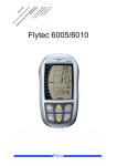
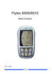
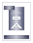
LIMITED ONE YEAR WARRANTY
Chaney Instrument Company warrants that all products it manufactures to be of good material and workmanship and to be free of
defects if properly installed and operated for a period of one year from date of purchase. REMEDY FOR BREACH OF THIS
WARRANTY IS EXPRESSLY LIMITED TO REPAIR OR REPLACEMENT OF DEFECTIVE ITEMS. Any product which, under normal use
and service, is proven to breach the warranty contained herein within ONE YEAR from date of sale will, upon examination by
Chaney, and at its sole option, be repaired or replaced by Chaney. In all cases, transportation costs and charges for returned
goods shall be paid for by the purchaser. Chaney hereby disclaims all responsibility for such transportation costs and charges.
This warranty will not be breached, and Chaney will give no credit for products it manufactures which shall have received normal
wear and tear, been damaged, tampered, abused, improperly installed, damaged in shipping, or repaired or altered by others than
authorized representatives of Chaney.
THE ABOVE-DESCRIBED WARRANTY IS EXPRESSLY IN LIEU OF ALL OTHER WARRANTIES, EXPRESS OR IMPLIED, AND ALL
OTHER WARRANTIES ARE HEREBY EXPRESSLY DISCLAIMED, INCLUDING WITHOUT LIMITATION THE IMPLIED WARRANTY OF
MERCHANTABILITY AND THE IMPLIED WARRANTY OF FITNESS FOR A PARTICULAR PURPOSE. CHANEY EXPRESSLY DISCLAIMS
ALL LIABILITY FOR SPECIAL, CONSEQUENTIAL OR INCIDENTAL DAMAGES, WHETHER ARISING IN TORT OR BY CONTRACT FROM
ANY BREACH OF THIS WARRANTY. SOME STATES DO NOT ALLOW THE EXCLUSION OR LIMITATION OF INCIDENTAL OR
CONSEQUENTIAL DAMAGES, SO THE ABOVE LIMITATION OR EXCLUSION MAY NOT APPLY TO YOU. CHANEY FURTHER DISCLAIMS
ALL LIABILITY FROM PERSONAL INJURY RELATING TO ITS PRODUCTS TO THE EXTENT PERMITTED BY LAW. BY ACCEPTANCE
OF ANY OF CHANEY’S EQUIPMENT OR PRODUCTS, THE PURCHASER ASSUMES ALL LIABILITY FOR THE CONSEQUENCES
ARISING FROM THEIR USE OR MISUSE. NO PERSON, FIRM OR CORPORATION IS AUTHORIZED TO ASSUME FOR CHANEY ANY
OTHER LIABILITY IN CONNECTION WITH THE SALE OF ITS PRODUCTS. FURTHERMORE, NO PERSON, FIRM OR CORPORATION IS
AUTHORIZED TO MODIFY OR WAIVE THE TERMS OF THIS PARAGRAPH, AND THE PRECEDING PARAGRAPH, UNLESS DONE IN
WRITING AND SIGNED BY A DULY AUTHORIZED AGENT OF CHANEY. THIS WARRANTY GIVES YOU SPECIFIC LEGAL RIGHTS, AND
YOU MAY ALSO HAVE OTHER RIGHTS WHICH VARY FROM STATE TO STATE.
For in-warranty repair, please contact:
Customer Care Department
Chaney Instrument Company
965 Wells Street
Lake Geneva, WI 53147
This device complies with part 15 of the FCC rules. Operation is subject to the
following two conditions:
1- This device may NOT cause harmful interference, and
2- This device must accept any interference received, including interference that
may cause undesired operation.
NOTE: This equipment has been tested and found to comply with the limits for a Class B digital device,
pursuant to Part 15 of the FCC rules. These limits are designed to provide reasonable protection
against harmful interference in a residential installation. This equipment generates, uses and can
radiate radio frequency energy and, if not installed and used in accordance with the instructions, may
cause harmful interference to radio communications. However, There is no guarantee that interference
will not occur in a particular installation. If this equipment does cause harmful interference to radio or
television reception, which can be determined by turning the equipment off and on, the user is
encouraged to try to correct the interference by one or more of the following measures:
• Reorient or relocate the receiving antenna.
• Increase the separation between the equipment and the receiver.
• Connect the equipment into an outlet on a circuit different from that to which the
receiver is connected.
• Consult the dealer or an experienced radio/TV technician for help.
NOTE: The manufacturer is not responsible for any radio or TV interference caused by unauthorized
modifications to this equipment. Such modifications could void the user authority to operate the
equipment.
01035 INST 080911
Professional Weather Center
model #01035
Instruction Manual
Contents
1
Introduction: About the Professional Weather Center
Section 1: Setup
2
Installing Batteries and Powering On
4
Installing the Wireless Multi-Sensor
6
Setting Time and Date
8
Language Selection
9
USB PC Connection
10 USB Mode Setup/Use
11 Setting Unit Preferences
Section 2: Using the Professional Weather Center
13 Basic Functions
14 Wind Speed & Direction
15 Temperature & Humidity
16 Weather Forecast
17 Atmospheric Pressure
18 Rainfall
19 Weather Category History
20 Weather Category Alarms
23 Weather TickerTM Functions
Introduction
The AcuRite® Professional Weather Center with Integrated
Multi-Sensor collects outside weather data and sends the data via
wireless signal to the included Display Console via a low-power
radio frequency. This weather center has been designed to be
easy to install and use, without compromising any of the
professional weather tracking features you want.
The AcuRite® 5-in-1 Multi-Sensor is completely wireless and
contains a self-emptying rain collector for measuring rainfall,
temperature/humidity sensor, anemometer, and a wind vane. The
anemometer measures wind speed, and the wind vane measures
wind direction. The Integrated Multi-Sensor is battery powered
and features a solar panel for running an internal aspirating fan.
The internal fan will assist in drawing ambient air through to
reduce the heating effects of solar radiation, resulting in a more
accurate air temperature measurement.
Section 3: Tips and Troubleshooting
26 Maintenance Tips
27 Troubleshooting
29 Calibrating Your Weather Center
30 Specifications & Reference
The sleek display console houses a liquid crystal display (LCD)
which will calculate and display all the weather data received
from the Integrated Multi-Sensor outside. The Display Console can
be powered via AC power utilizing the included AC adaptor, or it
can be powered with batteries. The Display Console has
professional weather features such as alarms for high and low
conditions, daily/all time record highs and lows, and an area for
displaying a multitude of extra weather information- the Weather
TickerTM. The display console also features a USB connection to
send your weather data to your PC.
Parts List
Please read through this manual to learn more about the
AcuRite® Professional Weather Center. Keep this manual for
future reference.
model #01035
1. Display console with table top stand
2. 5-in-1 multi-sensor
3. 5-in-1 multi-sensor mounting bracket
4. Snap-in debris filter for 5-in-1 rain collector
5. AC power adaptor for display console
6. USB cable
Please DO NOT return product to the retail store.
For technical assistance and product return information, please call
Customer Care: 877-221-1252 Mon. - Fri. 7:00 A.M. to 7:00 P.M. (CST)
1
SETUP
Installing Batteries - 5-in-1 Multi-Sensor
ABC
SET “ABC” SWITCH TO MATCH
DISPLAY CONSOLE
“ABC” SWITCH SELECTION
!
Installing Batteries - Display Console
ABC
!
SET “ABC” SWITCH TO MATCH
SENSOR “ABC” SWITCH SELECTION
Remove
Battery
Compartment
Cover
WRITE DOWN YOUR
DEVICE I.D. / M.A.C.
You will need the device ID
number that is printed on
the back of the display
for (OPTIONAL) online
connectivity,
so keep it handy!
1 Remove Battery
Compartment
Cover
3 Remove Tape
& Rain Gauge
Stabilizer
-discard-
2 Install 4
“AA” Alkaline*
Batteries
Install 6
“AA”
Alkaline
Batteries
Connect
power
adaptor
*install lithium batteries for
use in temperatures
below -4ºF
NOTE: Make sure to remove the tape and small plastic rain gauge
stabilizer installed in the bottom of the sensor housing. The rain
gauge will not function until this is removed.
BATTERIES MUST BE INSTALLED FOR THE INTEGRATED SENSOR
TO OPERATE: The integrated sensor features a solar cell for
collecting sunlight and converting it into usable power, this feature is
intended to EXTEND the life of the batteries you install. This sensor
REQUIRES batteries be installed to operate, and will not function on
solar power alone.
PLEASE DISPOSE OF OLD OR DEFECTIVE BATTERIES IN AN ENVIRONMENTALLY
SAFE WAY AND IN ACCORDANCE WITH YOUR LOCAL LAWS AND
REGULATIONS.
2
The display console will operate under battery power OR AC power
alone, however, it is recommended that batteries be installed to
retain records and to ensure continued operation during a power
outage.
Note that the Weather Ticker will display a scrolling welcome
message and basic instructions after powering on.
IMPORTANT: set the time and date as soon as possible, weather
history data is driven by the time and date and will record incorrect
time and date information if the time and date are not set correctly.
3
SETUP
SETUP
Installing the Wireless 5-in-1 Multi-Sensor
After installing batteries into the Wireless Multi-sensor, you must
choose a location to install the sensor. To ensure that your
professional weather center performs at its best, follow these
guidelines to choose a mounting location for the wireless multi-sensor:
NO OBSTRUCTIONS ABOVE
OR AROUND
Install the wireless
multi-sensor with the solar
cell facing south to properly
orient the wind direction
vane.
UTH
SO
INSTALL AWAY FROM HEAT & HUMIDITY SOURCES:
DO NOT Place the wireless multi-sensor near localized heat
sources like heaters, air conditioners, chimneys and exhaust
vents. Install the wireless multi-sensor away from asphalt or
concrete as these surfaces radiate heat from the sun. Also avoid
installing the sensor near pools, spas, or other bodies of water
as these water sources may affect the accuracy of the humidity.
(1.5 meters)
INSTALL AWAY FROM SPRINKLER HEADS:
DO NOT install the wireless multi-sensor where it will be directly
sprayed by a sprinkler system, this will affect the rainfall
measurement accuracy and may force water into the housing.
WIND & RAIN OBSTRUCTIONS:
DO NOT mount the sensor with obstructions above it, as this will
ensure proper rainfall measurement. Also consider a mounting
location that has very little structures around the sensor, to
ensure proper wind speed and direction measurements.
INSTALLATION HEIGHT:
DO Mount the wireless multi-sensor at least 5 feet off the ground
(higher is better for accurate wind measurements) in an open
area NO FURTHER than 300 feet (100 meters) from the display
console. A typical installation would involve mounting the
bracket to a secured length of 2x4 or 4x4 wood (not included).
LEVEL INSTALLATION:
DO Install the wireless multi-sensor as level as possible to ensure
accurate rain and wind measurements. Use the bubble level on
the top to ensure a level installation.
SOLAR CELL ORIENTATION:
DO Install the sensor onto the mounting bracket with the solar cell
facing SOUTH. This is important to ensure that the cell receives as
much sun as possible, and also orients the wind direction
properly.
4
Choose an open location
with no obstructions above
or around the sensor for
accurate rain and wind
measurement.
Secure the included sensor
mounting bracket to a post
or pole (not included)
utilizing the included
hardware.
TO CLEAR DATA COLLECTED DURING INSTALLATION:
During the process of installation, internal sensors were likely
triggered-resulting in erroneous rainfall and wind measurements.
When installation is complete, you may want to clear out the
erroneous data from the display consoles memory.
To clear out the display consoles memory without having to reset the
clock and re-establish communication, press the “CLEAR TODAY”
button. This button will clear out any data that was recorded since
12:00 am that day. The “CLEAR TODAY” button is located on the
back of the display console within the battery compartment.
5
SETUP
Setting the Time & Date
After powering on the display console, you must set your local time
and date. It is important to do this as soon as possible, as the history
functions will utilize the clock and calendar to time stamp records
and data of interest.
After setting the clock upon initial startup, the display should
automatically bring you to the “SET DATE?” If “SET DATE?” is not
currently displayed, press the up or down buttons until “SET DATE?”
is displayed.
The default selected weather category on the display should be “SET
CLOCK” after initial power on. If “SET CLOCK” is not currently
displayed, press the up or down buttons until “SET CLOCK?” is
displayed.
1. Press the “ ” button to set the date
2. Adjust the month up or down
1. Press the “ ” button to set the clock
2. Adjust the hour up or down,note the “AM” and “PM” indicators
3. Press the “ ” button to confirm hour selection
4. Adjust the minute up or down
3. Press the “
” button to confirm month selection
4. Adjust the day up or down
5. Press the “
” button to confirm day selection.
6. Adjust the year up or down.
7. Press the “
5. Press the “
” button to confirm minute selection.
” button to confirm year selection.
The Date setting procedure is now complete.
The clock setting procedure is now complete.
6
7
SETUP
SETUP
Language Selection
USB PC Connection
The display console is designed for use in either English(default) or
French. To set the display to a different language, press the “ ”
button until you see the category read “SET LANG?” Press the “ ”
button to set the language, then press the “ ” button to select the
desired language. Press the “
” button again to confirm your
language selection.
The display console gives you the option to connect the display to
your PC for expanded functionality and features. The integrated USB
port for is located next to the power adaptor port within the battery
compartment.
NOTE: If the display runs out of power or is reset, English will be
display language as it is the default language selection.
Display Features
current
wind
direction
previous
two wind
directions
current
wind
speed
wind
speed
peak
current
outdoor
temperature
& trend
alarm on
indicator
wind
speed
one hour
average
current
outdoor
humidity
& trend
weather
select
multidisplay
rainfall
data
display
area
sensor
signal
strength
current
date
alarm
functions
display
area
history
records
display
area
currently selected
weather category
weather ticker
display area
(optional)
1. Go to www.acurite.com
and click on the “My Backyard
Weather” link and follow the
on-screen instructions for
installing software for your
USB connected weather
station display console.
www.AcuRite.com
2. Connect USB
cable to display
console
(PC)
3. Connect USB
cable to your
PC
PC CONNECT REQUIREMENTS: A PC running Windows® XP,
Windows® Vista, or Windows® 7 with an available USB port.
A high speed internet connection is required to use some of the
advanced features of the USB connect Acu-Link system.
8
9
SETUP
USB Connectivity
(optional)
Once you have installed the software from the website and connected
the USB cable to your PC, you must choose a USB mode to take
advantage of the USB connectivity..
The display console has 512kb of internal memory*, which is enough
space to log (save) about 2 weeks worth of weather data. When the
internal memory is nearing capacity, the weather ticker will display a
message informing you to download the internal memory to your PC
soon. This is done using the download application (available from
www.acurite.com).
The download to your PC will export the logged data from the display
console onto your PC as a simplified data-view CSV file
(Comma-separated values).
The display console web bridge mode can also be enabled to stream
live data to the internet to the AcuRite weather servers. From there,
you can access your home weather data from any internet-connected
PC or from your smart phone using the aculink app.
RUN UNLOAD
EXPORT
SOFTWARE TO CONSOLE
EXPORT TO
DATA TO
PC
CSV FILE
(optional)
USB Mode 1: Display logging ON
•Display console logs (saves) data internally every 12 minutes
•Run download software on your PC to export console data into CSV
(comma separated values- data sheet) file
USB Mode 2: Display logging OFF (DEFAULT)
•Display console DOES NOT log (save) any internal data
(if you choose NOT to connect the display console to your PC)
FOR MODES 3 & 4, YOU WILL NEED YOUR DEVICE I.D. / M.A.C. NUMBER TO
REGISTER FOR ONLINE ACCESS AND APP ACCESS TO YOUR WEATHER DATA.
THIS NUMBER IS LOCATED ON THE BACK OF THE DISPLAY CONSOLE
USB Mode 3: Web Bridge Mode/Display Logging ON
•Display console logs (saves) data internally every 12 minutes
•Sends data stream from your PC internet connection in real time**
in raw format to Acu-Rite weather servers. (automatic)
•Run download software on your PC to export console data into CSV
file
USB Mode 4: Web Bridge Mode/Display Logging OFF
•Display console DOES NOT log (save) any internal data
•Sends data stream from your PC internet connection in real time**
in raw format to Acu-Rite weather servers. (automatic)
Setting USB Mode
USB Modes Overview
LOGS DATA
INTERNALLY
EVERY
12 MINS.
USB Modes
SENDS DATA
TO ACURITE
SERVERS
VIEW DATA
ONLINE
& ON APP
USB
MODE
**
**
USB
MODE
**
**
To set the USB mode, you need to first select “SET USB MODE?” in
the center display area by pressing the up or down buttons. Press the
“ ” button to enter into USB set mode.
USB
MODE
1
USB
MODE
2
3
Press the up or down buttons to browse through the 4 different USB
modes. Press the “ ” button to confirm your selection.
4
* internal memory is not expandable
** Requires an “always-on” internet connection for continuous data streaming
10
11
SETUP
USE
Setting Unit preferences
Basic Functions
CHANGING UNITS
The Professional Wireless Weather Center comes pre-set from the
factory in standard units ( mph, ºF, etc.). You may wish to change to
metric units ( kph, ºC, etc.).
The Professional Wireless Weather Center was designed to give you
the most often used information at a glance. The following is an
overview of basic functions for everyday use.
To change the units, you need to first select “SET UNITS?” in the
center display area by pressing the up or down buttons.
WEATHER SELECT:
The “Weather Select” area of the display features heat index, dew
point, wind chill calculations, as well as indoor temperature and
humidity. Rainfall rate (inches per hour) can also be viewed in the
weather select area. To change the “Weather Select” category,
press the selection arrow button just to the left of the weather select
display area.
= Heat Index
1. Press the “
= Dew Point
” button to adjust the unit preference
= Wind Chill
2. Press the up or down buttons to select either “STAND” for standard
or “METRIC” for metric units.
3. Press the “
” button to confirm your desired selection
= Indoor Conditions
press the selection arrow to
change the weather select display
= Rainfall Rate (in./hr)
4. You will now see “WIND MPH”, press the up or down buttons to
select either MPH, KPH, or KNOTS for wind speed unit of
measurement.
5. Press the “ ” button again to confirm your desired selection
and exit “SET UNITS?” menu.
12
WIRELESS SIGNAL RECEPTION ICON:
The display console features a “SENSOR” signal reception icon to the
left of the clock display area. If there are a low number of “bars”
present, you may experience no temperature display ( “--” ) or
inaccuracy. Occasionally, due to intermittent physical obstructions (such
as vehicle traffic, etc.) or other environmental interference, the signal
may be lost. If the sensor batteries are low the signal will be lost as well.
After a signal loss- the display console will automatically begin to search
for the wireless multi-sensor and attempt to re-acquire the wireless signal.
In the event that the signal is lost completely and cannot be re-acquired,
the weather ticker will display “SENSOR SIGNAL LOST- CHECK BATTERIES
AND PLACEMENT”. See “troubleshooting” for more information.
13
USE
USE
Wind Speed & Direction
Temperature & Humidity
The display console features WIND SPEED PEAK, AVERAGE,
CURRENT WIND SPEED, CURRENT WIND DIRECTION, and WIND
DIRECTION RECENT HISTORY INDICATORS. All of the wind data
points are displayed in the center and upper left portion of the
display.
The display console features OUTDOOR TEMPERATURE &
HUMIDITY as well as INDOOR TEMPERATURE & HUMIDITY.
Outdoor temperature and humidity data points are shown in the
upper right portion of the display. Indoor readings are viewable in
the weather select display area.
TREND:
STEADY
exterior
TREND:
RISING
WIND SPEED PEAK:
The WIND SPEED PEAK will display the highest wind speed
recorded in the previous 60 minutes.
WIND SPEED AVERAGE:
The WIND SPEED AVERAGE will display the average of all the
wind speed numbers recorded in the previous 2 minutes.
CURRENT WIND SPEED:
The CURRENT wind speed will display the currently recorded
wind speed and is updated every 18 seconds.
CURRENT WIND DIRECTION:
The CURRENT WIND DIRECTION rosette graphic will display
the currently recorded direction that the wind is coming from,
this is updated every 18 seconds. The current wind directions is
represented by the “FULL ARROW” graphic.
INDOOR
TEMPERATURE & HUMIDITY
OUTDOOR
TEMPERATURE & HUMIDITY
OUTDOOR TEMPERATURE:
The OUTDOOR TEMPERATURE sensor is located within the
wireless multi-sensor. This sensor is fan-aspirated, which will
provide an accurate temperature measurement-even in direct
sunlight.
OUTDOOR HUMIDITY:
The OUTDOOR HUMIDITY sensor is located within the wireless
multi-sensor. This sensor is fan-aspirated, which will provide an
accurate overall humidity measurement.
TREND INDICATORS:
The OUTDOOR TEMPERATURE AND HUMIDITY displaysʼ both
feature a trend arrow indicator. One of the three arrow icons
will illuminate- indicating if the temperature or humidity is
RISING, STEADY, or FALLING.
RECENT HISTORY- WIND DIRECTION:
The RECENT HISTORY-WIND DIRECTION is the “memory” of
the last two wind direction readings. The last two readings are
represented by the “PARTIAL ARROW” bump graphics. This
feature will give you a good idea of the more general direction
the wind is coming from.
INDOOR TEMPERATURE & HUMIDITY:
The INDOOR TEMPERATURE & HUMIDITY is viewed in the
WEATHER SELECT display. The INDOOR sensors are located
within the display console, which is ventilated for accuracy.
SEE “USING ALARMS”, “HISTORY” AND “WEATHER TICKER” TO
EXPLORE MORE ADVANCED WIND FEATURES
SEE “USING ALARMS”, “HISTORY” AND “WEATHER TICKER” TO
EXPLORE MORE ADVANCED TEMPERATURE & HUMIDITY FEATURES
14
15
USE
USE
Weather Forecast
Atmospheric Pressure
FORECAST: 14 day learning mode
This weather station has a patented “fourteen day learning mode”
calibration process. During this learning mode the weather station
will make altitude calculations that may affect the accuracy of the
forecast. Once the 14 day learning mode process is complete, the
learning mode icon will disappear and the weather forecast should
be ready for superior operation.
Atmospheric Pressure is defined as the pressure at any location on
the Earth, caused by the weight of the column of air above it. At sea
level, atmospheric pressure has an average value of one atmosphere
and gradually decreases as altitude increases. Also called
barometric pressure.
learning mode progress indicator
...after 3 days
...half-way
completed
...one day
to go
FORECAST: future forecast icon
The display console features a weather forecast icon which gives you
the predicted weather forecast for the next 12 to 24 hours based on
an advanced algorithm that observes the changes in barometric
pressure and temperature. The FORECAST icon will then predict the
future (next 12 to 24 hours) weather forecast. This weather station
will provide the most accurate forecast that a single station weather
instrument can provide.
PRODUCT REGISTRATION
The weight of the atmosphere that envelopes Earth exerts pressure
on all points of the planet's surface. Meteorologists use barometers
to measure this atmospheric pressure (also called barometric
pressure). At sea level the atmospheric pressure is approximately 1
kilogram per square centimeter (14.7 pounds per square inch),
which will cause a column of mercury in a mercury barometer to rise
760 millimeters (30.4 inches). Variations in the atmospheric pressure
greatly affect the weather. Low pressure generally brings rain. In
areas of low air pressure, the air is less dense and relatively warm,
which causes it to rise. The expanding and rising air naturally cools,
and the water vapor in the air condenses, forming clouds and the
drops that fall as rain. In high pressure areas, the air is dense and
relatively cool, which causes it to sink. The water vapor in the sinking
air doesnʼt condense, resulting in clear skies.
PRESSURE:
The display console
features a pressure
read-out, just to the
right of the forecast
icon. The pressure
readout area will also
indicate if the pressure
is FALLING, STEADY, or
RISING.
To receive product updates
and information, Go to
www.AcuRite.com
Register a Product
16
17
USE
USE
Rainfall
Weather Category History Functions
RAINFALL EVENT:
The “RAINFALL EVENT” display will give you the rainfall total
from the current rain event. A weather system may come into
your area very slowly, and may rain over many hours or days
without many breaks. The rainfall event total accounts for this
and will continue to display the total until the rain event is over.
RAINFALL MONTH TOTAL:
The “MONTH” display will give you the rainfall total from the
current calendar month.
RAINFALL TOTAL:
The “TOTAL” display will give you the rainfall total recorded
since the display console and wireless multi-sensor were
powered on.
HISTORY MODE:
Each weather category (example- “OUTDOOR TEMP” category
shown below) will display todayʼs LOW and/or HIGH record by
default.
To view the all time low record for the currently selected weather
category, press the “HISTORY MODE” (
) button. The display will
show the all time low record as well as the month/date and year the
record was set. The history display will return to default after 15
seconds of no button activity.
To view the all time high record for the currently selected weather
category, press the “HISTORY MODE” (
) BUTTON AGAIN. The
display will show the all time high record as well as the month/date
and year the record was set. The history display will return to default
after 15 seconds of no button activity.
= Event Total
= Month Total
= All-Time Total
RAINFALL RATE:
The “RAINFALL RATE” display will calculate how many inches of rain
would accumulate in a one hour time period, based on the current
rainfall rate.
Rainfall Rate Shown:
1.33 inches per hour
currently selected
weather category
OTHER HISTORY RECORDS ARE DISPLAYED AUTOMATICALLY IN THE
WEATHER TICKER DISPLAY WHEN RELEVANT. SEE “WEATHER TICKER”
SECTION OF THIS MANUAL FOR MORE DETAILS
press the selection arrow to
change the weather select display
18
19
USE
USE
Weather Category Alarm Functions
WEATHER ALARMS:
Each weather category (example- “OUTDOOR TEMP” category
shown below) features alarm options. The alarm options are
displayed to the left of the currently selected weather category.
Alarms are all set to “OFF” by default upon powering on the display
console.
NOTE: Some weather categories will only have either low alarm OR
high alarm options. For example, WIND SPEED only has a HIGH
wind speed alarm. In these cases, only the relevant alarms for the
selected weather category may be set.
ALARM VALUE ADJUST MODE:
To adjust an alarm value for the currently selected weather category,
press AND HOLD the “ALARM” button for the alarm you wish to set.
Note the adjust (ADJ) indicator
press and HOLD “ALARM”
to enter into adjust mode
To adjust the alarm value, press the down or up buttons. When you
are finished making adjustments to the alarm value, press the
“ALARM” button again to confirm your adjustments.
TURNING ALARMS ON or OFF:
After you have adjusted and set an alarm value, you will note that
the alarm is NOT automatically turned on. This is done to help prevent
“false alarms” and also allows you to set all your preferred alarm
values ahead of time without having to turn them all off when you
are finished.
To turn an alarm ON, press the alarm button. You will note the
“OFF” will change to “ON” momentarily, and then the alarm value
will be displayed. This alarm is now “ON”, and the display console
will alert you when this value is reached with an audible alarm and
an alarm icon indicator on the display.
ADJ
press “ALARM” to
turn alarm on or off
SILENCE A SOUNDING ALARM:
When an alarm is sounding, the weather category display will
automatically change to show the affected category and alarm
(flashing). The affected weather data on the display console will also
flash.
The alarm will sound initially for a few minutes, then silence itself.
The alarm will then sound every few minutes afterwards until one of
the following takes place.
1. “SNOOZE”- To silence a sounding alarm, press any button. This
will act similar to the “SNOOZE” function on an alarm clock. The
alarm will silence, but will sound again if the alarm condition still
exists later.
press to adjust
the alarm value
down or up
20
2. Turn the alarm “OFF”- The only way to permanently silence any
potential alarms is to turn the alarm “OFF”.
21
USE
USE
Weather Category Alarm Notes
Weather TickerTM
RAIN ALARM NOTE:
The “RAIN ALARM” can either be set to ON or OFF, no numerical
value can be set. If set to “ON”, the rain alarm will sound as soon as
the first amount of rain is recorded.
The WEATHER TICKERTM is a scrolling text area at the bottom of the
main console display. This area will automatically display an array of
relevant messages, like extra weather details and records.
STORM ALARM NOTE:
The “STORM ALARM” can either be set to ON or OFF, no numerical
value can be set. If set to “ON”, the STORM alarm will sound as
soon as a large ATMOSPHERIC PRESSURE DROP is observed by the
display console. A large pressure drop will usually indicate an
approaching storm.
CAUTION: the storm alarm feature is NOT intended to be a safety
device and should not be considered a warning system. Your local
weather warning system and the national weather service should be
your main source for severe weather warnings and information.
SUMMARY OF AVAILABLE WEATHER ALARMS:
OUTDOOR TEMPERATURE ALARMS AVAILABLE: LOW & HIGH
OUTDOOR HUMIDITY ALARMS AVAILABLE: LOW & HIGH
WIND SPEED ALARM AVAILABLE: HIGH
RAIN ALARM AVAILABLE: START OF RAIN
HEAT INDEX ALARM AVAILABLE: HIGH
DEW POINT ALARMS AVAILABLE: LOW & HIGH
WIND CHILL ALARM AVAILABLE: LOW
INDOOR TEMP ALARMS AVAILABLE: LOW & HIGH
INDOOR HUMIDITY ALARMS AVAILABLE: LOW & HIGH
AUTOMATIC DEFAULT WEATHER TICKER DISPLAY:
There are default WEATHER TICKERTM messages that will display on
an automatic cycle every day, such as MOON PHASE and
FORECAST, as well as others. Below is an overview of the daily
default WEATHER TICKERTM messages.
• FORECAST= a text readout of the 12-24 hour future forecast
• MOON PHASE= the current moon phase
• INDOOR COMFORT= dry, OK or humid
• IT FEELS LIKE __ OUTSIDE= this is a calculation based on
temperature, humidity and wind speed which will tell you how the
temperature actually feels like
• OUTDOOR TEMP THIS WEEK HIGH __= highest temperature
recorded this calendar week.
• OUTDOOR TEMP THIS WEEK LOW __= lowest temperature
recorded this calendar week.
• OUTDOOR TEMP THIS MONTH HIGH __= highest temperature
recorded this calendar month.
• OUTDOOR TEMP THIS MONTH LOW __= lowest temperature
recorded this calendar month.
You may also MANUALLY cycle through all the available weather
ticker messages by pressing the “ ” button at any time.
These messages can be removed or added back into the automatic
weather ticker display whenever you wish. To learn how to remove
or add messages to the WEATHER TICKERTM , see “CUSTOMIZING
THE WEATHER TICKERTM ”
STORM ALARM AVAILABLE: LARGE PRESSURE DROP
CYCLE button
manually cycles
through all currently
available weather messages
22
23
USE
USE
Weather TickerTM Extra Messages
Customizing the Weather TickerTM
EXTRA WEATHER TICKER MESSAGES:
In addition to the automatic general daily messages, there are extra
automatic messages which provide additional interesting details
about the current weather conditions. Below is an overview of the
extra WEATHER TICKERTM messages.
The WEATHER TICKERTM allows for a certain amount of customizing.
This customizing feature allows you to be in control; you may choose
which general weather messages will be displayed on the WEATHER
TICKERTM display.
• NEW HIGH TEMPERATURE RECORD __= will display when there
is a new HIGH temperature record recorded (outdoor)
• NEW LOW TEMPERATURE RECORD __= will display when there
is a new LOW temperature record recorded (outdoor)
• NEW WIND SPEED RECORD TODAY__= will display when a new
high wind speed record is recorded
• CURRENT RAINFALL RATE __ inches per hour= will display the
rainfall rate (inches per hour) when the rainfall rate is steady enough
and duration is long enough to be calculated
• CURRENT RAIN EVENT STARTED__= will display when the current
rainfall event started
• NO RAIN RECORDED SINCE__= will display how many DAYS
have elapsed since the last rainfall was recorded by the integrated
wireless sensor
To take quick stock of what messages are included or removed from
the automatic WEATHER TICKERTM cycle, press the “ ” button to
go through each available message manually. The area to the left of
each message will display the “X” if the message has been removed
from the automatic WEATHER TICKERTM cycle, and a “ ” if it is
included in the automatic WEATHER TICKERTM.
While manually cycling through the available WEATHER TICKERTM
messages using the “ ” button, you may then press the “remove”
button to remove the currently selected message from the automatic
message cycle, or press the “add” button to add/include the
message in the automatic cycle.
Please note that you MUST be manually (using the “ ” button)
cycling through the messages to mark them to be removed OR
added, pressing the “remove” button when in normal automatic
cycle mode will not remove messages.
The WEATHER TICKERTM will also display diagnostic messages as
well, such as “SENSOR BATTERIES LOW” and “SENSOR SIGNAL
LOST.” The WEATHER TICKERTM will also display any WEATHER
ALARM messages.
TICKER SPEED ADJUSTMENT:
The WEATHER TICKERTM text scrolling speed can be changed. use
the “UP” or “DOWN” buttons to select “TICKER SPEED”. Press the
“SET” button to adjust the ticker speed to SLOW, MEDIUM, or FAST.
24
A
B
EXAMPLE:
press “REMOVE” to
remove FORECAST
from automatic
ticker message cycle
CYCLE button
manually cycles
through all
standard
messages
25
B
EXAMPLE:
press “ADD” to
add/include FORECAST
back into automatic
cycle when viewing
manually
MAINTENANCE
TROUBLESHOOTING
DISPLAY CONSOLE MAINTENANCE:
Clean with a soft damp cloth, do not use caustic cleaners or
abrasives as these will damage the finish on the display console.
Keep away from dust and dirt and moisture, dust ventilation ports
regularly with a gentle puff of air, this will keep the indoor
temperature and humidity accurate.
INTEGRATED WIRELESS SENSOR MAINTENANCE:
Clean the housing with a damp cloth, do not use abrasive cleaners
or any materials that will mar the polished surfaces of the rain
collection funnel or the solar panel- this will result in decreased
performance and reliability.
Occasionally remove the rain collector screen cup and empty it. This
will filter out seeds and small sticks, etc. (the rain collector screen cup
is located within the rain funnel- remove from the top gently by
squeezing and pulling out).
Remove any foreign matter on the outside of the housing to allow for
free movement of wind vane and anemometer.
INSECTS: in most cases, insects will not pose a problem. However, in
some instances, insects may cause repeated obstructions to weather
measurement by nesting or building homes in or on the integrated
wireless sensor. In these cases, it may help to spray the housing with
a commercially available home insect guard/repellent product (not
included) to limit the problem. Please consult the insect repellent
manufacturers instructions and safety information before using.
BATTERY SAFETY: Clean the battery contacts and also those of the device prior to
battery installation. Remove batteries from equipment which is not to be used for an
extended period of time. Follow the polarity (+/-) diagram in the battery
compartment. Promptly remove dead batteries from the device. Dispose of used
batteries properly. Only batteries of the same or equivalent type as recommended
are to be used. DO NOT incinerate used batteries. DO NOT dispose of batteries in
fire, as batteries may explode or leak. DO NOT mix old and new batteries or types
of batteries (alkaline/standard). DO NOT use rechargeable batteries. DO NOT
recharge non-rechargeable batteries. DO NOT short-circuit the supply terminals.
26
Problem
Bad
Wireless Sensor
Reception
no bars
No Wireless Sensor Data
(no communication)
no bars and flashing
“ -- ” data
Possible Solution
Relocate the main unit and/or the wireless
sensor. Both units must be within 330 feet
(100m) from each other. Make sure both
units are placed at least 3 feet (.91 m) from
other electronic appliances and devices that
may interfere with the wireless
communication (such as TVʼs, microwaves,
computers etc). NOTE: It may take up to 20
minutes for the main unit to re-synchronize
with the sensor when batteries are replaced.
Use lithium batteries in sensor when
temperature is below -4ºF (-20ºC).
If wireless reception is bad (no bars), see
“Bad Reception” section above. The wireless
ID setting on each unit must match for all
units to communicate properly. See “Set
Wireless ID” on the next page.
Batteries may need replacing
Display Console
Screen Not Working
Check that AC adaptor is fully inserted if
running off AC power only
USB Connectivity
is not working
Check that the USB cable is securely
connected to the display console AND to
your PC USB port.
Confirm that the correct mode is selected.
I Cannot Access
my Data Online or
from the APP
Check that the USB cable is securely
connected to the display console AND to
your PC USB port.
Confirm that USB mode 3 or 4 is selected.
Make Certain that the display console is
powered on.
Confirm your display console DEVICE I.D. /
M.A.C. number is entered into your online
account correctly at www.acu-link.com
27
TROUBLESHOOTING
CALIBRATION
CALIBRATING THE DISPLAY CONSOLE:
The integrated wireless sensor is designed and engineered to provide
accurate measurements, the internal fan aspiration ensures a proper
ambient air temperature in most cases.
Set Wireless I.D.
This wireless thermometer
uses long range 433mhz
radio frequency for
communication.
If you feel that the placement or other environmental factors are
affecting the indoor or outdoor temperature or humidity readings,
the display console features a calibration feature for the indoor and
outdoor temperature and humidity. This allows you to adjust the
temperature or humidity reading up or down to compensate for the
affected reading.
In the event that you have
reception problems due to
interference, both the main
unit and the wireless sensor
have a selectable wireless
ID. The ID switches are
located within the battery
compartments of the
display console and the
integrated wireless sensor.
ABC
ABC
Both wireless ID
switches
must match
You may choose A, B or C;
but both the main unit and
the wireless sensor ID's
must match for successful
synchronization.
IMPORTANT NOTICE
Have questions about product setup or operation? We’re here to help!
24/7 Support:
www.acurite.com
Product Setup & Demo Videos
Product Manuals
Frequently Asked Questions
CALIBRATION PROCESS:
1. Select the affected category (outdoor temp example shown here)
2. Press AND HOLD the “DOWN”, “SET”, and “UP” buttons at the
same time for 15-20 seconds.
• The display console will “BEEP”, and all information on the display
will disappear except for the value you are calibrating.
• You will note the “ ” (calibrate) and the adjust up and down
arrows next to the value you are calibrating.
3. Press the “UP” or “DOWN” arrows to calibrate the display
console reading up or down from the actual reading.
4. Press the “SET” button to confirm your calibration adjustment.
• Note that the calibration icon will stay illuminated next to all
calibrated values. This is done so that you know that the value has
been calibrated.
Register your Product
Support Forum
Submit Feedback & Ideas
TOLL FREE:
EMAIL:
(877) 221-1252
[email protected]
7:00 a.m. - 7:00 p.m. CST
1-Year Warranty
Don’t forget! Register your
product at: www.acurite.com
28
press and HOLD all three buttons
for 15-20 seconds to calibrate
the calibration icon will
stay illuminated after
value is calibrated
29
SPECIFICATIONS
REFERENCE
Product Facts
#01035
Integrated Multi-Sensor Features
Batteries: 10 x “AA” (included)
Lithium Batteries Recommended below -4ºF
wind speed
anemometer
AC Power: 4.5 v adaptor (included)
Measurement Ranges
Outdoor Temperature: -40ºF to 158ºF
rainfall
collector
-40ºC to 70ºC
solar
panel
1% to 99%
Outdoor Humidity:
Outdoor temperature and humidity sensors are
internally fan aspirated to provide accurate
readings, even in sunlight
wind
direction
vane
0 to 99mph
Wind Speed:
0 to 159 kph
Wind Direction Indicators: 16 points
Rainfall:
0 to 99.99 in.
Indoor Temperature:
32ºF to 122ºF
Indoor Humidity:
16% to 98%
Backlight:
0ºC to 50ºC
mounting
point
Display Console Features
backlight
touch control
Yes
Backlight is momentary when weather center
display unit is on battery power, always on or off
when utilizing AC power adaptor (included).
Calibration:
Yes
The temperature and humidity readings on the
weather center display may be calibrated.
battery
access
and AC
adaptor/USB
port
weather select
button
(BACK)
Rainfall can be manually calibrated on the
5-in-1 wireless sensor. Basic tools required.
Wireless Range:
temperature
and humidity
battery
access
330 ft / 100 m MAX
alarm function
buttons
history records
button
Depending on home construction materials
Transmission Interval: 18 seconds
weather ticker
buttons
Patent numbers: 5,978,738; 6,076,044; 6,597,990; US 7,637,141 B2
and other patents applied for
Acurite and Acu-Link are trademarks and My Backyard Weather
is a registered trademark of Chaney Instrument Co.
965 Wells St. • Lake Geneva, WI 53147
30
31