1
Code: 538918 V
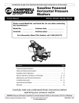
USER GUIDE
Edited/Published/Produced by:
Code: 538918 V
Olivetti S.p.A.
Gruppo Telecom Italia
Via Jervis, 77
Ivrea (TO) - Italy
www.olivetti.com
Trademarks: Microsoft and Windows are registered
trademarks of Microsoft Corporation.
Copyright © Olivetti, 2010
All rights reserved
Date of publication: March 2010
Other trademarks and trade names
may be used in this document to refer to either the entities
claiming the marks and names or their products.
Olivetti disclaims any proprietary interest in trademarks and
trade names other than its own.
This product is in compliance with requirements of European Directives
2004/108/EC e 2006/95/EC relating to electromagnetic compatibility and safety of
electrical equipment designed for use within certain voltage limits.
The Declaration of Conformity can be found at:
www.olivetti.com/site/public/support.asp
DIRECTIVE 2002/96/CE ON THE TREATMENT, COLLECTION,
RECYCLING AND DISPOSAL OF ELECTRIC AND ELECTRONIC
DEVICES AND THEIR COMPONENTS
1. FOR COUNTRIES IN THE EUROPEAN UNION (EU)
The disposal of electric and electronic devices as solid urban waste is
strictly prohibited: it must be collected separately. The dumping of these
devices at unequipped and unauthorized places may have hazardous
effects on health and the environment.
Offenders will be subjected to the penalties and measures laid down by
the law.
To dispose of our devices correctly:
a) Contact the Local Authorities, who will give you the practical
information you need and the instructions for handling the waste
correctly, for example: location and times of the waste collection
centres, etc.
b) When you purchase a new device of ours, give a used device similar
to the one purchased to our dealer for disposal.
The mark affixed to the product certifies that
the product satisfies the basic quality
Requirements.
Here by, Olivetti S.p.A. declares that this product is in compliance with the
essential requirements and other relevant provisions of Directive 1999/5/EC.
Directive 2002/96/CE
The ENERGY STAR program is an energy reduction plan introduced by
theUnited States Environmental Protection Agency in response to
environmental issues and for the purpose of advancing the development and
utilization of more energy efficient office equipment.
Energy Star qualified products help you save money and reduce
environmental impacts by meeting strict energy efficiency guidelines.
More information about Energy Star can be found at www.energystar.gov
The crossed dustbin symbol on the device means that:
- When it to be disposed of, the device is to be taken to
the equipped waste collection centres and is to be
handled separately from urban waste;
- Olivetti guarantees the activation of the treatment,
collection, recycling and disposal procedures in
accordance with Directive 2002/96/CE (and subsequent
amendments).
2. FOR OTHER COUNTRIES (NOT IN THE EU)
The treatment, collection, recycling and disposal of electric and electronic
devices will be carried out in accordance with the laws in force in the
country in question.
Table of Contents
Contents
Introducing the Notebook PC
General Overview ...................................................1-2
Notes For The User ...............................................1-2
Safety Precautions ..................................................1-3
Transportation Precautions .....................................1-5
Preparing your Notebook PC ..................................1-6
Knowing the Parts
Top Side .................................................................2-2
Right Side ...............................................................2-5
Right Side (cont.) ....................................................2-6
Left Side .................................................................2-7
Left Side (cont.) ......................................................2-8
Bottom Side ...........................................................2-9
Bottom Side (cont.) .............................................. 2-10
Getting Started
Installing and Customizing the Operating System for the
First Time ...............................................................3-2
Restoring the Computer's Factory Default Settings .3-4
Power System .........................................................3-6
Using AC Power ...................................................3-6
Using Battery Power .............................................3-8
Battery Care .........................................................3-9
Powering ON the Notebook PC .........................3-10
The Power-On Self Test (POST) ...........................3-11
Checking Battery Power .....................................3-12
Charging the Battery Pack ..................................3-13
Power Options ....................................................3-13
Emergency Shutdown .........................................3-14
Power Management Modes ................................3-15
Thermal Power Control .......................................3-16
Special Keyboard Functions ..................................3-17
Colored Hot Keys ...............................................3-17
Colored Hot Keys (cont.) .....................................3-18
Colored Hot Keys (cont.) .....................................3-19
Microsoft Windows Keys ....................................3-20
Keyboard as Cursors ...........................................3-20
Switches and Status Indicators ..............................3-21
Switches .............................................................3-21
Switches and Status Indicators (cont.) ...................3-22
Status Indicators .................................................3-22
Status Indicators (cont.) ......................................3-23
1
Table of Contents
Using the Notebook PC
Pointing Device .....................................................4-2
Using the Touchpad .............................................4-2
Touchpad Usage Illustrations ...............................4-3
Caring for the Touchpad .....................................4-5
Automatic Touchpad Disabling ............................4-6
Storage Devices ......................................................4-8
Hard Disk Drive ....................................................4-8
Memory (RAM) ....................................................4-8
Optical Drive ........................................................4-9
Optical Drive (Cont.) ........................................... 4-10
Optical Drive (Cont.) ........................................... 4-11
Flash Memory Card Reader ................................. 4-13
Express Card ..................................................... 4-15
Connections ......................................................... 4-17
Network Connection .......................................... 4-17
Wireless LAN Connection ................................... 4-19
Declarations and Safety Statements ....................... A-2
DVD-ROM Drive Information .............................. A-2
Technical specifications ......................................... B-2
2
Introducing the Notebook PC
Chapter 1: Introducing the Notebook PC
General Overview
Safety Precautions
Transportation Precautions
Preparing your Notebook PC
NOTE: Photos and icons in this document are used for artistic purposes only and do not show what is
actually used in the product itself.
1-1
1
1
Introducing the Notebook PC
General Overview
This document provides information on the various components in the Notebook PC and how to use them. The following
are the major sections of this document:
1. Introducing the Notebook PC
Introduces you to the Notebook PC and its documentation.
2. Knowing the Parts
Gives you information on the Notebook PC’s components.
3. Getting Started
Gives you information on getting started with the Notebook PC.
4. Using the Notebook PC
Gives you information on using the Notebook PC’s components.
Notes For The User
A few notes and warnings in bold are used throughout this document that you should be aware of in order to complete
certain tasks safely and completely. These notes have different degrees of importance as described below:
NOTE: Tips and information for special situations.
TIP: Tips and useful information for completing tasks.
IMPORTANT! Vital information that must be followed to prevent damage to data, components, or persons.
WARNING! Important information that must be followed for safe operation.
< > Text enclosed in < > or [ ] represents a key on the keyboard; do not actually type the < > or [ ] and the
[ ] enclosed letters.
1 - 2 General Overview
Introducing the Notebook PC
Safety Precautions
The following safety precautions will increase the life of the Notebook PC. Follow all precautions and instructions. Except
as described in this document, refer all servicing to qualified personnel. Do not use damaged power cords, accessories,
or other peripherals. Do not use strong solvents such as thinners, benzene, or other chemicals on or near the surface.
IMPORTANT! Disconnect the AC power and remove the battery pack(s) before cleaning. Wipe the
Notebook PC using a clean cellulose sponge or chamois cloth dampened with a solution of nonabrasive
detergent and a few drops of warm water and remove any extra moisture with a dry cloth.
DO NOT place on uneven or unsta-ble work surfaces.
Seek servicing if the casing has been damaged.
DO NOT place or drop objects on top and do not shove
any foreign objects into the Notebook PC.
DO NOT press or touch the display panel. Do not place
together with small items that may scratch or enter the
Notebook PC.
DO NOT expose to strong magnetic or electrical fields.
DO NOT expose to dirty or dusty environments. DO NOT
operate during a gas leak.
DO NOT expose to or use near liquids, rain, or moisture.
DO NOT use the modem during an electri-cal storm.
DO NOT leave the Notebook PC on your lap or any part of
the body in order to prevent discomfort or injury from heat
exposure.
Battery safety warnings: DO NOT throw the battery in fire.
DO NOT disassemble the battery. DO NOT short circuit the
contacts.
SAFE TEMP: This Notebook PC should only be used in
environ-ments with ambient temperatures between 5°C
(41°F) and 35°C (95°F).
INPUT RATING: Refer to the rating label on the bottom of
the Notebook PC and be sure that your power adapter
complies with the rating.
Safety Precautions 1 - 3
1
1
Introducing the Notebook PC
DO NOT throw the Notebook PC, battery pack or any of
its parts in municipal waste. Check local regulations for
disposal of electronic products.
CAUTION! Danger of explosion if the battery pack is
incorrectly replaced. Replace only with the same or equivalent type recommended by the manufacturer.
1 - 4 Safety Precautions
DO NOT carry or cover a Notebook PC that is powered
ON with any materials that will reduce air circulation such
as a carrying bag.
Introducing the Notebook PC
Transportation Precautions
To prepare the Notebook PC for transport, you should turn it OFF and disconnect all external peripherals to prevent
damage to the connectors. The hard disk drive’s head retracts when the power is turned OFF to prevent scratching of the
hard disk surface during transport. Therefore, you should not transport the Notebook PC while the power is still ON. Close
the display panel and check that it is latched securely in the closed position to protect the keyboard and display panel.
IMPORTANT! The Notebook PC’s surface is easily dulled if not properly cared for. Be careful not to rub or
scrape the Notebook PC surfaces.
Cover Your Notebook PC
Purchase a carrying bag to protect the Notebook PC from dirt, water, shock, and scratches.
Charge Your Batteries
If you intend to use battery power, be sure to fully charge your battery pack and any optional battery packs before going
on long trips. Remember that the power adapter charges the battery pack as long as it is plugged into the computer and
an AC power source. Be aware that it takes much longer to charge the battery pack when the Notebook PC is in use.
Airplane Precautions
Contact your airline if you want to use the Notebook PC on the airplane. Most airlines will have restrictions for using
electronic devices. Most airlines will allow electronic use only between and not during takeoffs and landings.
IMPORTANT! There are three main types of airport security devices: X-ray machines (used on items placed
on conveyor belts), magnetic detectors (used on people walking through security checks), and magnetic
wands (hand-held devices used on people or individual items). You can send your Notebook PC and
diskettes through airport X-ray machines. However, it is recommended that you do not send your
Notebook PC or diskettes through airport magnetic detectors or expose them to magnetic wands.
Transportation Precautions 1 - 5
1
1
Introducing the Notebook PC
Preparing your Notebook PC
These are only quick instructions for using your Notebook PC. Read the later pages for detailed information on using your
Notebook PC.
IMPORTANT! Selected models may feature display panels that do not fully open to a 180-degree angle,
with such models do not attempt to force the display panel beyond its limit as it may cause damage to
the device.
1. Install the battery pack
1 - 6 Preparing your Notebook PC
2. Connect the AC Power Adapter
Introducing the Notebook PC
3. Open the Display Panel
4. Turn ON the Notebook PC
IMPORTANT! When opening, do not force the display panel down to the table or else the hinges may
break! Never lift the Notebook PC by the display panel!
The power switch turns the Notebook PC ON and OFF or puts the Notebook PC into sleep or hibernation modes.
Actual behavior of the power switch can be customized in Windows Control Panel > Power Options > System Settings.
Preparing your Notebook PC 1 - 7
1
1
Introducing the Notebook PC
Page left intentionally blank
1 - 8 Preparing your Notebook PC
Knowing the Parts
Chapter 2: Knowing the Parts
Top Side
Right Side
Left Side
Bottom Side
NOTE: Photos and icons in this document are used for artistic purposes only and do not show what is
actually used in the product itself.
2-1
2
2
Knowing the Parts
Top Side
Refer to the diagram below to identify the components on this side of the Notebook PC.
NOTE: The keyboard will be different for each territory.
IMPORTANT! Selected models may feature display panels that do not fully open to a 180-degree angle,
with such models do not attempt to force the display panel beyond its limit as it may cause damage to
the device.
2 - 2 Top Side
Knowing the Parts
11
2
3
3
7
4
8
5
66
Top Side 2 - 3
2
2
Knowing the Parts
1
Camera
2
Display Panel
3
Audio Speakers
4
Power Switch
5
Keyboard
6
Touchpad and Buttons
7
Wireless Switch
8
Status Indicators
The built-in camera allows picture taking or video recording. Can be used with video conferencing and other interactive applications.
The Notebook PC uses an ultra-clear flat panel which provides excellent viewing like that of desktop monitors without any harmful
radiation or flickering, so it is easier on the eyes. Use a soft cloth without chemical liquids (use plain water if necessary) to clean the
display panel. WARNING: The display panel is fragile. Do not to bend or press the panel.
The built-in stereo speaker system allows you to hear audio without additional attachments. The multimedia sound system features an integrated digital audio controller that produces rich, vibrant sound (results improved with external stereo headphones or
speakers). Audio features are software controlled.
The power switch turns the Notebook PC ON and OFF or puts the Notebook PC into sleep or hibernation modes. Actual behavior
of the power switch can be customized in Windows Control Panel “Power Options.”
The keyboard provides keys with comfortable travel (depth at which the keys can be depressed) and palm rest for both hands. A
Windows function key is provided to help ease navigation in the Windows operating system.
The touchpad with its buttons is a pointing device that provides the same functions as a desktop mouse. A software-controlled
scrolling function is available after setting up the included touchpad utility to allow easy Windows or web navigation.
This switch allows you to toggle the Notebook PC’s wireless connection. See details for the switches in Section 3.
Status indicators represent various hardware/software conditions. See indicator details in Section 3.
2 - 4 Top Side
Knowing the Parts
Right Side
Refer to the diagram below to identify the components on this side of the Notebook PC.
1
2
1
Headphone Output Jack
2
Microphone Input Jack
3
USB Ports (2.0/1.1)
4
Optical Drive
3
4
5
6
The stereo headphone jack (1/8 inch) is used to connect the Notebook PC’s audio out signal to amplified speakers or headphones.
Using this jack automatically disables the built-in speakers.
The mono microphone jack (1/8 inch) can be used to connect an external microphone or output signals from audio devices. Using
this jack automatically disables the built-in microphone. Use this feature for video conferencing, voice narrations, or simple audio
recordings.
The USB (Universal Serial Bus) ports are compatible with USB 2.0 or USB 1.1 devices such as keyboards, pointing devices, cameras,
hard disk drives, printers, and scanners connected in a series up to 12Mbits/sec (USB 1.1) and 480Mbits/sec (USB 2.0). USB allows
many devices to run simultaneously on a single computer, with some peripherals acting as additional plug-in sites or hubs. USB
supports hot-swapping of devices so that most peripherals can be connected or disconnected without restarting the computer.
The Notebook PC comes in various models with different optical drives. The Notebook PC’s optical drive may support compact
discs (CD) and/or digital video discs (DVD) and may have recordable (R) or re-writable (RW) capabilities. See the marketing specifications for details on each model.
(continued on the next page)
Right Side 2 - 5
2
2
Knowing the Parts
Right Side (cont.)
1
5
2
3
4
5
6
Power (DC) Input
The supplied power adapter converts AC power to DC power for use with this jack. Power supplied through this jack supplies
power to the Notebook PC and charges the internal battery pack. To prevent damage to the Notebook PC and battery pack,
always use the supplied power adapter.
CAUTION: The adapter may become warm to hot when in use. be sure not to cover the adapter and keep
it away from your body.
6
Kensington® Lock Port
The Kensington® lock port allows the Notebook PC to be secured using Kensington® compatible Notebook PC security products.
These security products usually include a metal cable and lock that prevent the Notebook PC to be removed from a fixed object.
Some may also include a motion detector to sound an alarm when moved.
2 - 6 Right Side (cont.)
Knowing the Parts
Left Side
Refer to the diagram below to identify the components on this side of the Notebook PC.
1
1
Display (Monitor) Output
2
LAN Port
3
USB Port (2.0/1.1)
4
USB Port (2.0/1.1)
2
3
4
5
6
The 15-pin D-sub monitor port supports a standard VGA-compatible device such as a monitor or projector to allow viewing on a
larger external display.
The RJ-45 LAN port with eight pins is larger than the RJ-11 modem port and supports a standard Ethernet cable for connection to
a local network. The built-in connector allows convenient use without additional adapters.
The USB (Universal Serial Bus) port is compatible with USB 2.0 or USB 1.1 devices such as keyboards, pointing devices, cameras,
hard disk drives, printers, and scanners connected in a series up to 12Mbits/sec (USB 1.1) and 480Mbits/sec (USB 2.0). USB allows
many devices to run simultaneously on a single computer, with some peripherals acting as additional plug-in sites or hubs. USB
supports hot-swapping of devices so that most peripherals can be connected or disconnected without restarting the computer.
(continued on the next page)
Left Side 2 - 7
2
2
Knowing the Parts
Left Side (cont.)
1
5
ExpressCard Slot
6
Flash Memory Card Reader
2
3
4
5
6
One 26pin Express card slot is available to support an ExpressCard/34mm or ExpressCard/54mm expansion card. This interface is
faster by using a serial bus supporting USB 2.0 and PCI Express instead of the slower parallel bus used in the PC card slot. (Not
compatible with previous PCMCIA cards.)
This Notebook PC has a built-in high-speed memory card reader that can conveniently read from and write to many flash memory
cards used in devices such as digital cameras, MP3 players, mobile phones, and PDAs.
2 - 8 Left Side (cont.)
Knowing the Parts
Bottom Side
Refer to the diagram below to identify the components on this side of the Notebook PC.
7
2
1
11
3
Battery Pack
The battery pack is automatically charged when the Notebook PC is connected to an AC power source and maintains power to the
Notebook PC when AC power is not connected. This allows use when moving temporarily between locations. Battery time varies by
usage and by the specifications for this Notebook PC. The battery pack cannot be disassembled and must be purchased as a single unit.
(continued on the next page)
Bottom Side 2 - 9
2
2
Knowing the Parts
Bottom Side (cont.)
7
2
2
Hard Disk Drive Compartment
3
Memory (RAM) Compartment
11
3
The hard disk drive is secured in a compartment. Hard Disk Drive (HDD) is a non-volatile data storage device. It stores data on a
magnetic surface layered onto hard disk platters. Visit an authorized service center or retailer for more information on the hard
disk drive of your Notebook PC.
The memory compartment contains pre-installed RAM. RAM (Random Access Memory) is where operating system, application
programs, and data in current use are kept so that they can be quickly reached. Visit an authorized service center or retailer for
more information on the memory of your Notebook PC.
2 - 10 Bottom Side (cont.)
Getting Started
Chapter 3: Getting Started
Installing and Customizing the Operating System for the First Time
Restoring the Computer's Factory Default Settings
Power System
Special Keyboard Functions
Switches and Status Indicators
NOTE: Photos and icons in this document are used for artistic purposes only and do not show what is
actually used in the product itself.
3-1
3
3
Getting Started
Installing and Customizing the Operating System for the First Time
When installing Windows 7, certain information need to
be entered to configure and customize the system
according to the user's needs.
NOTE: The following procedure applies only to the
preinstalled version of Windows 7.
1. When powering on the computer for the first time,
after a brief initial screen startup phase, the Set Up
Windows screen is displayed allowing you to select in
which language you wish to use the operating system.
2. Click Next.
Select Country, Time, Currency and Keypad layout
to continue with the Set Up Windows.
3. Click Next.
Type a user name and a computer name to continue
with the Set Up Windows.
4. Click Next.
Type the Windows version serial number to continue
with the Set Up Windows.
NOTE: The serial number is found on the label affixed
on the back panel of the notebook.
5. Type serial number of your Windows version and start
the automatic activation procedure. Click Next to
continue.
3 - 2 Installing and Customizing the Operating System for the First Time
Getting Started
6. Upon completion the system will ask you to accept the
license agreement ("Accept the Licenze Agreement") .
7. Click Next to continue.
Set Help protect your computer and improve
Windows automatically to end the Windows
configuration procedure.
8. Review the time and data setting. Click Next to
continue.
3-3
3
3
Getting Started
Restoring the Computer's Factory Default Settings
Proceed as follows to restore the computer to its initial
factory default configuration (the configuration that the
computer was in at the time of purchase).
2. From the Advanced Startup Options menu, select
Repair Your computer.
You are prompted to select a keypad input mode.
WARNING! : Remember to attach the power
cord to the computer and to the electrical
outlet before starting so as to ensure that the
battery remains charged during the entire
reinstallation process.
1. Shortly after having pressed the power button on your
computer, repeatedly press the <F8> key on the
keypad until displaying the Advanced Boot Options
screen.
3. Select English and then click Next.
3 - 4 Restoring the Computer's Factory Default Settings
Getting Started
4. To continue, the System Recovery Options require
that you to type the User name and its associated
Password. The user (or users) that can be selected are
those that have been defined on the computer in use.
Type the User name and, if necessary, its associated
Password and then click OK. You can now select the
type of recovery to perform.
5. Select Startup Repair and then select Shut Down.
You are now prompted to confirm the selected
operation.
WARNING! This operation will delete all the data
that was loaded on the computer after its
purchase.
To continue, confirm by clicking Yes.
Wait for the system recovery operation to end
before powering off the computer. An interruption
of this operation will render the operating system
unusable.
Restoring the Computer's Factory Default Settings 3 - 5
3
3
Getting Started
Power System
Using AC Power
The Notebook PC power is comprised of two parts, the
power adapter and the battery power system. The power
adapter converts AC power from a wall outlet to the DC
power required by the Notebook PC. Your Notebook PC
comes with a universal AC-DC adapter. That means that
you may connect the power cord to any 100V-120V as well
as 220V-240V outlets without setting switches or using
power converters. Different countries may require that an
adapter be used to connect the provided US-standard AC
power cord to a different standard. Most hotels will
provide universal outlets to support different power cords
as well as voltages. It is always best to ask an experienced
traveler about AC outlet voltages when bringing power
adapters to another country.
TIP: You can buy travel kits for the Notebook PC that includes power and modem adapters for almost
every country.
With the AC power cord connected to the AC-DC converter, connect the AC power cord to an AC outlet (preferably with
surge-protection) and then connect the DC plug to the Notebook PC. Connecting the AC-DC adapter to the AC outlet
first allows you to test the AC outlet’s power and the AC-DC converter itself for compatibility problems before connecting
the DC power to the Notebook PC. The power indicator on the adapter (if available) will light if the power is within
accepted ranges.
3 - 6 Power System
Getting Started
IMPORTANT! Damage may occur if you use a different adapter to power the Notebook PC or use the
Notebook PC’s adapter to power other electrical devices. If there is smoke, burning scent, or extreme heat
coming from the AC-DC adapter, seek servicing. Seek servicing if you suspect a faulty AC-DC adapter. You
may damage both your battery pack(s) and the Notebook PC with a faulty AC-DC adapter.
NOTE: This Notebook PC may come with either a two or three-prong plug depending on territory. If a
three-prong plug is provided, you must use a grounded AC outlet or use a properly grounded adapter to
ensure safe operation of the Notebook PC.
WARNING! THE POWER ADAPTER MAY BECOME WARM TO HOT WHEN IN USE. BE SURE NOT TO COVER
THE ADAPTER AND KEEP IT AWAY FROM YOUR BODY.
Power System 3 - 7
3
3
Getting Started
Using Battery Power
The Notebook PC is designed to work with a removable battery pack. The battery pack consists of a set of battery cells
housed together. A fully charged pack will provide several hours of battery life, which can be further extended by using
power management features through the BIOS setup. Additional battery packs are optional and can be purchased
separately through a Notebook PC retailer.
Installing and Removing the Battery Pack
Your Notebook PC may or may not have its battery pack installed. If your Notebook PC does not have its battery pack
installed, use the following procedures to install the battery pack.
IMPORTANT! Never attempt to remove the battery pack while the Notebook PC is turned ON, as this may
result in the loss of working data.
To install the battery pack:
3 - 8 Power System
To remove the battery pack:
Getting Started
IMPORTANT! Only use battery packs and power adapters supplied with this Notebook PC or
specifically approved by the manufacturer or retailer for use with this model or else damage may
occur to the Notebook PC.
Battery Care
The Notebook PC’s battery pack, like all rechargeable batteries, has a limit on the number times it can be recharged. The
battery pack’s useful life will depend on your environment temperature, humidity, and how your Notebook PC is used. It
is ideal that the battery be used in a temperature range between 5°C and 35°C (41°F and 95°F). You must also take into
account that the Notebook PC’s internal temperature is higher than the outside temperature. Any temperatures above or
below this range will shorten the life of the battery. But in any case, the battery pack’s usage time will eventually decrease
and a new battery pack must be purchased from an authorized dealer for this Notebook PC. Because batteries also have
a shelf life, it is not recommended to buy extras for storing.
WARNING! For safety reasons, DO NOT throw the battery in fire, DO NOT short circuit the contacts, and
DO NOT disassemble the battery. If there is any abnormal operation or damage to the battery pack caused
by impact, turn OFF the Notebook PC and contact an authorized service center.
Power System 3 - 9
3
3
Getting Started
Powering ON the Notebook PC
The Notebook PC’s power-ON message appears on the screen when you turn it ON. If necessary, you may adjust the
brightness by using the hot keys. If you need to run the BIOS Setup to set or modify the system configuration, press [F2]
upon bootup to enter the BIOS Setup. If you press [Tab] during the splash screen, standard boot information such as the
BIOS version can be seen. Press [ESC] and you will be presented with a boot menu with selections to boot from your
available drives.
NOTE: Before bootup, the display panel flashes when the power is turned ON. This is part of the Notebook
PC’s test routine and is not a problem with the display.
IMPORTANT! To protect the hard disk drive, always wait at least 5 seconds after turning OFF your
Notebook PC before turning it back ON.
WARNING! DO NOT carry or cover a Notebook PC that is powered ON with any materials that will reduce
air circulation such as a carrying bag.
3 - 10 Power System
Getting Started
The Power-On Self Test (POST)
When you turn ON the Notebook PC, it will first run through a series of software-controlled diagnostic tests called the
Power-On Self Test (POST). The software that controls the POST is installed as a permanent part of the Notebook PC’s
architecture. The POST includes a record of the Notebook PC’s hardware configuration, which is used to make a
diagnostic check of the system. This record is created by using the BIOS Setup program. If the POST discovers a difference
between the record and the existing hardware, it will display a message on the screen prompting you to correct the
conflict by running BIOS Setup. In most cases the record should be correct when you receive the Notebook PC. When the
test is finished, you may get a message reporting “No operating system found” if the hard disk was not preloaded with
an operating system. This indicates that the hard disk is correctly detected and ready for the installation of a new
operating system.
Self Monitoring and Reporting Technology
The S.M.A.R.T. (Self Monitoring and Reporting
Technology) checks the hard disk drive during POST and
gives a warning message if the hard disk drive requires
servicing. If any critical hard disk drive warning is given
during bootup, backup your data immediately and run
Windows disk checking program. To run Window’s disk
checking program: click Start > select Computer > rightclick a hard disk drive icon > choose Properties > click the
Tools tab > click Check Now > click Start. You can also
select “Scan ... sectors” for more effective scan and repair
but the process will run slower.
IMPORTANT! If warnings are still given during bootup after running a software disk checking utility, you
should take your Notebook PC in for servicing. Continued use may result in data loss.
Power System 3 - 11
3
3
Getting Started
Checking Battery Power
The battery system implements the Smart Battery standard under the Windows environment, which allows the battery to
accurately report the amount of charge left in the battery. A fully-charged battery pack provides the Notebook PC a few
hours of working power. But the actual figure varies depending on how you use the power saving features, your general
work habits, the CPU, system memory size, and the size of the display panel.
NOTE: Screen captures shown here are examples
only and may not reflect what you see in your
system.
Right-click the battery icon
Left-click the battery icon
NOTE: You will be warned when battery power is low. If you continue to ignore the low battery warnings,
the Notebook PC eventually enters suspend mode (Windows default uses STR).
WARNING! Suspend-to-RAM (STR) does not last long when the battery power is depleted. Suspendto-Disk (STD) is not the same as power OFF. STD requires a small amount of power and will fail if no power
is available due to complete battery depletion or no power supply (e.g. removing both the power adapter
and battery pack).
3 - 12 Power System
Getting Started
Charging the Battery Pack
Before you use your Notebook PC on the road, you will have to charge the battery pack. The battery pack begins to charge
as soon as the Notebook PC is connected to external power using the power adapter. Fully charge the battery pack before
using it for the first time. A new battery pack must completely charge before the Notebook PC is disconnected from
external power. It takes a few hours to fully charge the battery when the Notebook PC is turned OFF and may take twice
the time when the Notebook PC is turned ON. The battery status indicator on the Notebook PC turns OFF when the
battery pack is charged.
NOTE: The battery stops charging if the temperature is too high or the battery voltage is too high.
WARNING! Do not leave the battery pack discharged. The battery pack will discharge over time. If not
using a battery pack, it must continued to be charged every three months to extend recovery capacity or
else it may fail to charge in the future.
Power Options
The power switch turns ON and OFF the Notebook PC or putting the Notebook PC into sleep or hibernation modes. Actual
behavior of the power switch can be customized in Windows Control Panel “Power Options.”
For other options, such as “Switch User, Restart, Sleep, or Shut Down,” click the arrowhead next to the lock icon.
Restarting or Rebooting
After making changes to your operating system, you may
be prompted to restart the system. Some installation
processes will provide a dialog box to allow restart. To
restart the system manually, choose Restart.
Power System 3 - 13
3
3
Getting Started
IMPORTANT! To protect the hard drive, wait at least 5 seconds after turning OFF your Notebook PC before
turning it back ON.
Emergency Shutdown
In case your operating system cannot properly turn OFF or
restart, there is a manual way to shutdown your Notebook
PC:
Hold the power button
over 4 seconds
IMPORTANT! Do not use emergency shutdown while data is being written; doing so can result in loss
or destruction of your data.
3 - 14 Power System
Getting Started
Power Management Modes
The Notebook PC has a number of automatic or adjustable power saving features that you can use to maximize battery
life and lower Total Cost of Ownership (TCO). You can control some of these features through the Power menu in the
BIOS Setup. ACPI power management settings are made through the operating system. The power management features
are designed to save as much electricity as possible by putting components into a low power consumption mode as often
as possible but also allow full operation on demand.
Sleep and Hibernate
Power management settings can be found in the Windows >
Control Panel > Power Options. In System Settings, you can
define “Sleep/Hibernate” or “Shut Down” for closing the
display panel or pressing the power button. “Sleep” and
“Hibernate” saves power when your Notebook PC is not in
use by turning OFF certain components. When you resume
your work, your last status (such as a document scrolled
down half way or email typed half way) will reappear as if
you never left. “Shut Down” will close all applications and
ask if you want to save your work if any are not saved.
Power System 3 - 15
3
Getting Started
3
Sleep is the same as Suspend-to-RAM (STR). This function
stores your current data and status in RAM while many
components are turned OFF. Because RAM is volatile, it
requires power to keep (refresh) the data. Click the Start
button and the arrowhead next to the lock icon to see this
option. You can also use the keyboard shortcut [Fn F1] to
activate this mode. Recover by pressing any keyboard key
except [Fn]. (NOTE: The power indicator will blink in this
mode).
The computer is shipped enabled for power management
and the default settings are in compliance with Energy Star
5.0 requirements:
- the device automatically enters in sleep mode within 30
minutes of user inactivity
- the display automatically enters in sleep mode within 15
minutes of user inactivity.
To wake up the computer from this state press any
key on the keypad or press the power button.
Hibernate is the same as Suspend-to-Disk (STD) and stores
your current data and status on the hard disk drive.
By doing this, RAM does not have to be periodically
refreshed and power consumption is greatly reduced but
not completely eliminated because certain wake-up
components like LAN needs to remain powered.
“Hibernate” saves more power compared to “Sleep”. Click
the Start button and the arrowhead next to the lock icon
to see this option. Recover by pressing the power button.
(NOTE: The power indicator will be OFF in this mode).
Thermal Power Control
There are three power control methods for controlling the Notebook PC’s thermal state. These methods cannot be
configured by the user and should be known in case the Notebook PC should enter these states. The following
temperatures represent the chassis temperature (not CPU).
•
•
•
The fan turns ON for active cooling when temperature reaches the safe upper limit.
The CPU decreases speed for passive cooling when the temperature exceeds the safe upper limit.
The system shuts down for critical cooling when temperature exceeds the maximum safe upper limit.
3 - 16 Power System
Getting Started
Special Keyboard Functions
Colored Hot Keys
The following defines the colored hot keys on the
Notebook PC’s keyboard. The colored commands can only
be accessed by first pressing and holding the function key
while pressing a key with a colored command.
NOTE: The Hot Key locations on the function keys may vary depending on model but the functions should
remain the same.
Moon Icon (F1): Places the Notebook PC in suspend mode (either Save-to-RAM or Save-to-Disk depending on sleep button setting in
power management setup).
Signal Icon (F2): Wireless Models Only: Toggles the internal wireless LAN ON or OFF with an on-screen-display. When enabled, the
corresponding wireless indicator will light. Windows software settings are necessary to use the wireless LAN.
Open Sun Icon (F3):
Increases the display brightness.
Filled Sun Icon (F4):
Decreases the display brightness.
LCD/Monitor Icons (F5): Toggles between the Notebook PC’s LCD display and an external monitor in this series: Notebook PC LCD > External Monitor -> Both. (This function does not work in 256 Colors, select High Color in Display Property Settings.) NOTE: Must
connect an external monitor “before” booting up.
(continued on the next page)
Special Keyboard Functions 3 - 17
3
3
Getting Started
Colored Hot Keys (cont.)
Speaker X Icon (F7):
Toggles the speakers ON and OFF (only in Windows OS).
Speaker Low Icon (F8):
Decreases the speaker volume (only in Windows OS).
Speaker High Icon (F9):
Increases the speaker volume (only in Windows OS).
Bluetooth Icon (F11): Toggles the internal bluetooth ON or OFF with an on-screen-display. Windows software settings are necessary
to connect to bluetooth devices. (on selected models only).
Camera Icon (F12): Toggles the built-in camera ON (enabled) and OFF (disabled).Disabling the camera will prevent any images or
videos from being taken and transmitted accidentally.
Scr Lk (NumLk): Toggles the “Scroll Lock” ON and OFF. Allows you to use a larger portion of the keyboard for cell navigation.
Battery Icon (Home): Toggles Intel’s Configuration Center ON and OFF.
(continued on the next page)
3 - 18 Special Keyboard Functions
Getting Started
Colored Hot Keys (cont.)
Play/Pause Icon ( ):
Plays or pauses media in the media player.
Stop Icon ( ):
Stops a media player during playback.
Rewind Icon ( ):
Rewinds or moves the media a step backwards during playback.
Fast-forward Icon ( ):
Fast-forwards or moves the media a step forward during playback.
Special Keyboard Functions 3 - 19
3
3
Getting Started
Microsoft Windows Keys
There are two special Windows keys on the keyboard as described below.
The key with the Windows Logo activates the Start menu located at the bottom left of the Windows desktop.
The other key, that looks like a Windows menu with a small cursor, activates the properties menu and is equivalent to pressing the
right mouse button on a Windows object.
Keyboard as Cursors
The keyboard can be used as cursors while Number Lock is
ON or OFF in order to increase navigation ease while
entering numeric data in spreadsheets or similar
applications.
With Number Lock OFF, press [Fn] and one of the cursor
keys shown below. For example [Fn][8] for up, [Fn][K] for
down, [Fn][U] for left, and [Fn][O] for right.
With Number Lock ON, use [Shift] and one of the cursor
keys shown below. For example [Shift][8] for up, [Shift][K]
for down, [Shift][U] for left, and [Shift][O] for right.
NOTE: The red arrows are illustrated here for your reference. They are not labeled on the keyboard as
shown here.
3 - 20 Special Keyboard Functions
Getting Started
Switches and Status Indicators
Switches
Wireless Switch
Wireless Models Only: Toggles the internal wireless LAN or Bluetooth (on selected models) ON or OFF with an on-screen display. When
enabled, the corresponding wireless indicator will light. Windows software settings are necessary to use the wireless LAN or Bluetooth.
(continued on the next page)
Switches and Status Indicators 3 - 21
3
3
Getting Started
Switches and Status Indicators (cont.)
Status Indicators
Capital Lock Indicator
Indicates that capital lock [Caps Lock] is activated when lighted. Capital lock allows some of the keyboard letters to type using capitalized letters (e.g. A, B, C). When the capital lock light is OFF, the typed letters will be in the lower case form (e.g. a,b,c).
Bluetooth Indicator
This is only applicable on models with internal Bluetooth (BT). This indicator will light to show that the Notebook PC’s built-in Bluetooth (BT) function is activated.
Drive Activity Indicator
Indicates that the Notebook PC is accessing one or more storage device(s) such as the hard disk. The light flashes proportional to
the access time.
Wireless Indicator
This is only applicable on models with built-in wireless LAN and/or built-in Bluetooth. When the built-in wireless LAN and/or built-in
Bluetooth is enabled, this indicator will light. (Windows software settings are necessary.)
(continued on the next page)
3 - 22 Switches and Status Indicators (cont.)
Getting Started
Status Indicators (cont.)
Battery Charge Indicator
The battery charge indicator shows the status of the battery’s power as follows:
ON: The Notebook PC’s battery is charging when AC power is connected.
OFF: The Notebook PC’s battery is charged or completely drained.
Blinking: Battery power is less than 10% and the AC power is not connected.
Number Lock Indicator
Indicates that number lock [Num Lk] is activated when lighted. Number lock allows some of the keyboard letters to act as numbers
for easier numeric data input.
Switches and Status Indicators (cont.) 3 - 23
3
3
Getting Started
Page left intentionally blank
3 - 24 Switches and Status Indicators (cont.)
Using the Notebook PC
Chapter 4: Using the Notebook PC
Pointing Device
Storage Devices
Connections
NOTE: Photos and icons in this document are used for artistic purposes only and do not show what is
actually used in the product itself.
4-1
4
4
Using the Notebook PC
Pointing Device
The Notebook PC’s integrated touchpad pointing device is
fully compatible with all two/three-button and scrolling
knob PS/2 mice. The touchpad is electrostatic sensitive and
contains no moving parts; therefore, mechanical failures
can be avoided. A device driver is still required for working
with some application software.
Cursor
Movement
IMPORTANT! Do not use any objects in place of
your finger to operate the touchpad or else
damage may occur to the touchpad’s surface.
Left Click
Right Click
Using the Touchpad
Light pressure with the tip of your finger is all that is
required to operate the touchpad. Because the touchpad is
electrostatic sensitive, objects cannot be used in place of
your fingers. The touchpad’s primary function is to move
the cursor around or select items displayed on the screen
with the use of your fingertip instead of a standard desktop
mouse. The following illustrations demonstrate proper use
of the touchpad.
Moving The Cursor
Place your finger in the center of the touchpad and slide in
a direction to move the cursor.
4 - 2 Pointing Device
Slide finger
forward
Slide finger
left
Slide finger
right
Slide finger
backward
Using the Notebook PC
Scrolling (on selected models)
Slide your finger up or down on the right side to scroll a
window up or down.
NOTE: A software-controlled scrolling function is
available after setting up the included touchpad
utility to allow easy Windows or web navigation.
Scroll Up
Scroll Down
Touchpad Usage Illustrations
Clicking/Tapping - With the cursor over an item, press the left button or use your fingertip to touch the touchpad lightly,
keeping your finger on the touchpad until the item is selected. The selected item will change color. The following 2
examples produce the same results.
Clicking
Press the left cursor button and release.
Tapping
Lightly but rapidly strike the touchpad.
Pointing Device 4 - 3
4
4
Using the Notebook PC
Double-clicking/Double-tapping - This is a common skill for launching a program directly from the corresponding icon you
select. Move the cursor over the icon you wish to execute, press the left button or tap the pad twice in rapid succession,
and the system launches the corresponding program. If the interval between the clicks or taps is too long, the operation
will not be executed. You can set the double-click speed using the Windows Control Panel “Mouse.” The following 2
examples produce the same results.
Double-Clicking
Press the left button twice and release.
Double-Tapping
Lightly but rapidly strike the touchpad twice.
Dragging - Dragging means to pick up an item and place it anywhere on the screen you wish. You can move the cursor
over the item you select, and while keeping the left button depressed, moving the cursor to the desired location, then
release the button. Or, you can simply double-tap on the item and hold while dragging the item with your fingertip. The
following illustrations produce the same results.
Dragging-Clicking
Hold left button and slide finger on touchpad.
4 - 4 Pointing Device
Dragging-Tapping
Lightly strike the touchpad twice, sliding finger on
touchpad during second strike.
Using the Notebook PC
Caring for the Touchpad
The touchpad is pressure sensitive. If not properly cared for, it can be easily damaged. Take note of the following
precautions.
•
•
•
•
Make sure the touchpad does not come into contact with dirt, liquids or grease.
Do not touch the touchpad if your fingers are dirty or wet.
Do not rest heavy objects on the touchpad or the touchpad buttons.
Do not scratch the touchpad with your finger nails or any hard objects.
NOTE: The touchpad responds to movement not to force. There is no need to tap the surface too hard.
Tapping too hard does not increase the responsiveness of the touchpad. The touchpad responds best to
light pressure.
Pointing Device 4 - 5
4
4
Using the Notebook PC
Automatic Touchpad Disabling
Windows can automatically disable the Notebook PC’s touchpad when an external USB mouse is attached. This feature
is normally OFF, to turn ON this feature, select the option in Windows Control Panel > Mouse Properties > Device Settings
(or USB mouse connection).
Control Panel Home
Models with Synaptics touchpad.
Select this option
to enable this feature.
4 - 6 Pointing Device
Using the Notebook PC
Control Panel - Classic View
Models with ALPS touchpad.
Select this option
to enable this feature.
Pointing Device 4 - 7
4
4
Using the Notebook PC
Storage Devices
Storage devices allow the Notebook PC to read or write documents, pictures, and other files to various data storage
devices. This Notebook PC has the following storage devices:
•
•
•
•
•
Hard Disk Drive
Memory (RAM)
Optical Drive
Flash Memory Card Reader
ExpressCard
Hard Disk Drive
Hard disk drives have higher capacities and operate at much faster speeds than floppy disk drives and optical drives. The
Notebook PC comes with a replaceable hard disk drive. Current hard drives support S.M.A.R.T. (Self Monitoring and
Reporting Technology) to detect hard disk errors or failures before they happen.
IMPORTANT! Poor handling of the Notebook PC may damage the hard disk drive. Handle the Notebook
PC gently and keep it away from static electricity and strong vibrations or impact. The hard disk drive is
the most delicate component and will likely be the first or only component that is damaged if the
Notebook PC is dropped.
Memory (RAM)
RAM (Random Access Memory) is the component in a computer where the operating system, application programs, and
data in current use are kept so that they can be quickly reached by the computer’s processor. Upon startup the BIOS
automatically detects the amount of memory in the system and configures CMOS accordingly during the POST (PowerOn-Self-Test) process.
4 - 8 Storage Devices
Using the Notebook PC
Optical Drive
Inserting an optical disc
1. While the Notebook PC’s power is ON, press the drive’s
eject button and the tray will eject out partially.
2. Gently pull on the drive’s front panel and slide the tray
completely out. Be care-ful not to touch the drive lens
and other mechanisms. Make sure there are no
obstructions that may get jammed under the drive’s
tray.
Storage Devices 4 - 9
4
4
Using the Notebook PC
Optical Drive (Cont.)
3. Hold the disc by the edge and face the disc’s printed
side up. Push down on both sides of the disc’s center
until the disc snaps onto the hub. The hub should be
higher than the disc when correctly mounted.
4. Slowly push the drive’s tray back in. The drive will begin
reading the table of con-tents (TOC) on the disc. When
the drive stops, the disc is ready to be used.
NOTE: It is normal to hear as well as feel the disc spinning with great intensity in the optical drive while
data is read.
4 - 10 Storage Devices
Using the Notebook PC
Optical Drive (Cont.)
Removing an optical disc
Eject the tray and gently pry the edge of the disc upwards
at an angle to remove the disc from the hub.
Emergency eject
The emergency eject is located in a hole on the optical drive
and is used to eject the optical drive tray in case the
electronic eject does not work. Do not use the emergency
eject in place of the electronic eject. Note: Make sure not
to stab the activity indicator located in the same area.
Actual location will
vary by model.
Storage Devices 4 - 11
4
4
Using the Notebook PC
Using the Optical Drive
Optical discs and equipment must be handled with care because of the precise mechanics involved. Keep in mind the
important safety instructions from your disc suppliers. Unlike desktop optical drives, the Notebook PC uses a hub to hold
the disc in place regardless of the angle. When inserting a disc, it is important that the disc be pressed onto the center
hub or else the optical drive tray will scratch the disc.
WARNING! If the disc is not properly locked onto the center hub, the disc can be damaged when the tray
is closed. Always watch the disc closely while closing the tray slowly to prevent damage.
An optical drive letter should be present regardless of the presence of a disc in the drive. After the disc is properly inserted,
data can be accessed just like with hard disk drives; except that nothing can be written to or changed on the disc. Using
the proper software, a CD-RW drive or DVD+CD-RW drive can allow CD-RW discs to be used like a hard drive with writing,
deleting, and editing capabilities.
Vibration is normal for high-speed optical drives due to unbalanced discs or prints. To decrease vibration, use the
Notebook PC on an even surface and do not place labels on the disc.
Listening to Audio CDs
The optical drives can play audio CDs, but only the DVD-ROM drive can play DVD audio. Insert the audio CD and Windows
automatically opens an audio player and begins playing. Depending on the DVD audio disc and installed software, it may
require that you open a DVD player to listen to DVD audio. You can adjust the volume using hotkeys or Windows speaker
icon on the taskbar.
4 - 12 Storage Devices
Using the Notebook PC
Flash Memory Card Reader
Normally a memory card reader must be purchased separately in order to use memory cards from devices such as digital
cameras, MP3 players, mobile phones, and PDAs. This Notebook PC has a built-in memory card reader that can use many
flash memory cards as shown in the example below. The built-in memory card reader is not only convenient, but also
faster than most other forms of memory card readers because it utilizes the internal high-bandwidth PCI bus.
IMPORTANT! Flash memory card compatibility varies depending on Notebook PC model and flash memory
card specifications. Flash memory card specifications constantly change so compatibility may change
without warning.
Flash Memory Card Examples
Storage Devices 4 - 13
4
4
Using the Notebook PC
MMC (Multimedia Card)
MMC Plus
RS-MMC (Reduced Size) (with MMC adapter)
SD (Secure Digital)miniSD (with SD adapter)
SDHC (Secure Digital High Capacity)microSD (with SD adapter)
Memory stick (MS) / PRO / MagicGate / Select
Memory Stick Duo/Duo Pro/MagicGate (with MS adapater)
Memory Stick Micro (with MS adapter)
IMPORTANT! Never remove cards while or immediately after reading, copying, formatting, or deleting
data on the card or else data loss may occur.
WARNING! To prevent data loss, use “Windows Safely Remove Hardware” on the taskbar before
removing the flash memory card
4 - 14 Storage Devices
Using the Notebook PC
Express Card
One 26pin Express card slot is available to support one ExpressCard/34mm or one ExpressCard/54mm expansion card.
This new interface is faster by using a serial bus supporting USB 2.0 and PCI Express instead of the slower parallel bus
used in the PC card slot. (Not compatible with previous PCMCIA cards).
Inserting an ExpressCard
1. If there is an ExpressCard socket protec-tor, remove it
using the “Removing an ExpressCard” instructions
below.
Be sure the ExpressCard
is level when inserting.
2. Insert the ExpressCard with the connector side first and
label side up. Standard Ex-pressCards will be flush
with the Notebook PC when fully inserted.
Storage Devices 4 - 15
4
4
Using the Notebook PC
3. Insert the ExpressCard with the connector side first and
label side up. Standard Ex-pressCards will be flush
with the Notebook PC when fully inserted.
Removing an ExpressCard
The ExpressCard slot does not have an eject button. Press
the ExpressCard inwards and release to eject the
ExpressCard. Carefully pull the ejected ExpressCard out of
the socket.
4 - 16 Storage Devices
Using the Notebook PC
Connections
Network Connection
Connect a network cable, with RJ-45 connectors on each end, to the modem/network port on the Notebook PC and the
other end to a hub or switch. For 100 BASE-TX / 1000 BASE-T speeds, your network cable must be category 5 or better
(not category 3) with twisted-pair wiring. If you plan on running the interface at 100/1000Mbps, it must be connected to
a 100 BASE-TX / 1000 BASE-T hub (not a BASE-T4 hub). For 10Base-T, use category 3, 4, or 5 twisted-pair wiring. 10/100
Mbps Full-Duplex is supported on this Notebook PC but requires connection to a network switching hub with “duplex”
enabled. The software default is to use the fastest setting so no user-intervention is required.
1000BASE-T (or Gigabit) is only supported on selected models.
Twisted-Pair Cable
The cable used to connect the Ethernet card to a host (generally a Hub or Switch) is called a straight-through Twisted Pair
Ethernet (TPE). The end connectors are called RJ-45 connectors, which are not compatible with RJ-11 telephone
connectors. If connecting two computers together without a hub in between, a crossover LAN cable is required (FastEthernet model). (Gigabit models support auto-crossover so a crossover LAN cable is optional).
Connections 4 - 17
4
4
Using the Notebook PC
Example of the Notebook PC connected to a Network Hub or Switch for use with the built-in Ethernet
controller.
Network Hub or Switch
LAN
connector
Network cable with RJ-45 connectors
4 - 18 Connections
Using the Notebook PC
Wireless LAN Connection
The optional built-in wireless LAN is a compact easy-to-use wireless Ethernet adapter. Implementing the IEEE 802.11
standard for wireless LAN (WLAN), the optional built-in wireless LAN is capable of fast data transmission rates using
Direct Sequence Spread Spectrum (DSSS) and Orthogonal Frequency Division Multiplexing (OFDM) technologies on
2.4GHz/5GHz frequencies. The optional built-in wireless LAN is backward compatible with the earlier IEEE 802.11
standards allowing seamless interfacing of wireless LAN standards.
The optional built-in wireless LAN is a client adapter that supports Infrastructure and Ad-hoc modes giving you
flexibility on your existing or future wireless network configurations for distances up to 40 meters between the client
and the access point.
To provide efficient security to your wireless communication, the optional built-in wireless LAN comes with a 64-bit/
128-bit Wired Equivalent Privacy (WEP) encryption and Wi-Fi Protected Access (WPA) features.
Ad-hoc mode
The Ad-hoc mode allows the Notebook PC to connect to
another wireless device. No access point (AP) is required
in this wireless environment.
These are examples of the Notebook PC
connected to a Wireless Network.
Notebook PC
Desktop PC
(All devices must install optional 802.11 wireless LAN adapters).
PDA
Connections 4 - 19
4
4
Using the Notebook PC
Infrastructure mode
The Infrastructure mode allows the Notebook PC and
other wireless devices to join a wireless network created
by an Access Point (AP) (sold separately) that provides a
central link for wireless clients to communicate with each
other or with a wired network.
Notebook PC
Desktop PC
(All devices must install optional 802.11 wireless LAN adapters).
Access
Point
PDA
4 - 20 Connections
Using the Notebook PC
Windows Wireless Network Connection
Connecting to a network
1. Switch ON the Wireless function if necessary for your
model (see switches and/or special keyboard functions
in Section 3).
2. You should see the “Connections are available“
network icon.
3. Select “Show Wireless” if you have many networks in
your area.
Connections 4 - 21
4
4
Using the Notebook PC
4. Select the wireless network you want to connect to.
5. Right click on the network icon and select Connect to
a network.
4 - 22 Connections
6. When connecting, you may have to enter a password.
7. After connection has been established, “Connected”
will be shown.
Appendix A
Appendix A
Declarations and Safety Statements
NOTE: Photos and icons in this document are used for artistic purposes only and do not show what is
actually used in the product itself.
A-1
A
A
Appendix A
Declarations and Safety Statements
DVD-ROM Drive Information
The Notebook PC comes with an optional DVD-ROM drive or a CD-ROM drive. In order to view DVD titles, you must install
your own DVD viewer software. Optional DVD viewer software may be purchased with this Notebook PC. The DVD-ROM
drive allows the use of both CD and DVD discs.
Regional Playback Information
Playback of DVD movie titles involves decoding MPEG2 video, digital AC3 audio and decryption of CSS protected content.
CSS (sometimes called copy guard) is the name given to the content protection scheme adopted by the motion picture
industry to satisfy a need to protect against unlawful content duplication.
Although the design rules imposed on CSS licensors are many, one rule that is most relevant is playback restrictions on
regionalized content. In order to facilitate geographically staggered movie releases, DVD video titles are released for specific geographic regions as defined in “Region Definitions” below. Copyright laws require that all DVD movies be limited
to a particular region (usually coded to the region at which it is sold). While DVD movie content may be released for multiple regions, CSS design rules require that any system capable of playing CSS encrypted content must only be capable of
playing one region.
NOTE: The region setting may be changed up to five times using the viewer software, then it can only
play DVD movies for the last region setting. Changing the region code after that will require factory re
setting which is not covered by warranty. If resetting is desired, shipping and resetting costs will be at
the expense of the user.
A - 2 Declarations and Safety Statements
Appendix A
Region Definitions
Region 1
Canada, US, US Territories
Region 2
Czech, Egypt, Finland, France, Germany, Gulf States, Hungary, Iceland, Iran, Iraq, Ireland, Italy, Japan, Netherlands, Norway, Poland, Portugal, Saudi Arabia, Scotland, South Africa, Spain, Sweden, Switzerland, Syria, Turkey, UK, Greece,
Former Yugoslav Republics, Slovakia
Region 3
Burma, Indonesia, South Korea, Malaysia, Philippines, Singapore, Taiwan, Thailand, Vietnam
Region 4
Australia, Caribbean (Except US Territories), Central America, New Zealand, Pacific Islands, South America
Region 5
CIS, India, Pakistan, Rest of Africa, Russia, North Korea
Region 6
China
Declarations and Safety Statements A - 3
A
A
Appendix A
Optical Drive Safety Information
Laser Safety Information
Internal or external optical drives sold with this Notebook PC contains a CLASS 1 LASER PRODUCT. Laser classifications
can be found in the glossary at the end of this user’s manual.
WARNING! Making adjustments or performing procedures other than those specified in the user’s manual
may result in hazardous laser exposure. Do not attempt to disassemble the optical drive. For your safety,
have the optical drive serviced only by an authorized service provider.
Service warning label
CAUTION! INVISIBLE LASER RADIATION WHEN OPEN. DO NOT STARE INTO BEAM OR VIEW DIRECTLY WITH
OPTICAL INSTRUMENTS.
1 - 4 Declarations and Safety Statements
Appendix B
Appendix B
Technical specifications
NOTE: The specifications listed in this Appendix are correct at the time of going to press. Certain items
(particularly processor types/speeds) may be changed, delayed or updated due to the manufacturer's
release schedule. Check with your service center for details.
Technical specifications B - 1
B
B
Appendix B
Technical
specifications
BIOS
Interfaces
American Megatrend
Four USB 2.0 ports
One Headphone-out jack
One Microphone-in jack
One LAN RJ-45 jack
One DC input jack
One external monitor port
One 12.7 mm CD, DVD+/-RW optical drive
Processor
Storage
Intel® I3 330
One 320 GB SATA (Serial) hard drive
Core Logic
Security
Intel® HM55
Kensington Lock
Display
Comunication
15.6” - LED-backlit, 16:9 format
Audio
IEEE 802.11 b/g/n Intel My WiFi
Memory
Realtek ALC269
Two 2 x 2W audio speakers
10Mbps/100Mbps/1000Mbps Ethernet LAN
DDRIII (DDR3) 800/1600 MHz memory
Two Dual-channel modules, 1GB each
Video Adapter
Chipset-embedded GFX with up to
763MB shared memory
B - 2 Technical specifications
Pointing Device
Incorportated TouchPad (integrated
scrolling key functionality)
Integrated 1.3M pixel PC camera
Bluetooth EDR 2.1
Operating System
Windows 7 Professional Edition
Keyboard
Card Reader
Digital key keyboard (with embedded
numeric keypad)
Embedded 3-in-1 card reader
(MMC/SD/MS)
Appendix B
Slot
Dimensions & Weight
One Mini-card slot (for PCIe-type wireless
LAN module)
389mm (width) x 249mm (depth) x 34.5mm
(height)
Power Management
Theft proof
Wake On LAN
Wake On USB
Gravity sensor (G-sensor)
Power
Full range AC/DC adapter
AC input: 100 - 240 V, 50 - 60 HzDC DC
DC output: 19V, 3.42A (65 Watts)
Battery
11,1V - 4800mAh - 54Wh Lithium-ion
battery pack
Environmental Specs
Temperature
Operating: 5 °C - 35 °C
Non-operating: -20 °C - 60 °C
Relative humidity
Operating: 20% - 80%
Non-operating: 10% - 90%
Technical specifications B - 3
B
B
Appendix B
Page left intentionally blank
B - 4 Technical specifications
Edited/Published/Produced by:
Code: 538918 V
Olivetti S.p.A.
Gruppo Telecom Italia
Via Jervis, 77
Ivrea (TO) - Italy
www.olivetti.com
Trademarks: Microsoft and Windows are registered
trademarks of Microsoft Corporation.
Copyright © Olivetti, 2010
All rights reserved
Date of publication: March 2010
Other trademarks and trade names
may be used in this document to refer to either the entities
claiming the marks and names or their products.
Olivetti disclaims any proprietary interest in trademarks and
trade names other than its own.
This product is in compliance with requirements of European Directives
2004/108/EC e 2006/95/EC relating to electromagnetic compatibility and safety of
electrical equipment designed for use within certain voltage limits.
The Declaration of Conformity can be found at:
www.olivetti.com/site/public/support.asp
DIRECTIVE 2002/96/CE ON THE TREATMENT, COLLECTION,
RECYCLING AND DISPOSAL OF ELECTRIC AND ELECTRONIC
DEVICES AND THEIR COMPONENTS
1. FOR COUNTRIES IN THE EUROPEAN UNION (EU)
The disposal of electric and electronic devices as solid urban waste is
strictly prohibited: it must be collected separately. The dumping of these
devices at unequipped and unauthorized places may have hazardous
effects on health and the environment.
Offenders will be subjected to the penalties and measures laid down by
the law.
To dispose of our devices correctly:
a) Contact the Local Authorities, who will give you the practical
information you need and the instructions for handling the waste
correctly, for example: location and times of the waste collection
centres, etc.
b) When you purchase a new device of ours, give a used device similar
to the one purchased to our dealer for disposal.
The mark affixed to the product certifies that
the product satisfies the basic quality
Requirements.
Here by, Olivetti S.p.A. declares that this product is in compliance with the
essential requirements and other relevant provisions of Directive 1999/5/EC.
Directive 2002/96/CE
The ENERGY STAR program is an energy reduction plan introduced by
theUnited States Environmental Protection Agency in response to
environmental issues and for the purpose of advancing the development and
utilization of more energy efficient office equipment.
Energy Star qualified products help you save money and reduce
environmental impacts by meeting strict energy efficiency guidelines.
More information about Energy Star can be found at www.energystar.gov
The crossed dustbin symbol on the device means that:
- When it to be disposed of, the device is to be taken to
the equipped waste collection centres and is to be
handled separately from urban waste;
- Olivetti guarantees the activation of the treatment,
collection, recycling and disposal procedures in
accordance with Directive 2002/96/CE (and subsequent
amendments).
2. FOR OTHER COUNTRIES (NOT IN THE EU)
The treatment, collection, recycling and disposal of electric and electronic
devices will be carried out in accordance with the laws in force in the
country in question.
Code: 538918 V
USER GUIDE