1
E84 Analysis Application User Manual
Version 2.8
Data Recoding Mode
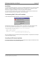
The initial mode for the E84 Analysis application is Data Recording Mode. When recording live data, the
Data Recording Mode provides the interface to start and stop data recording. When connected to the
E84 DLD, Data Recording Mode also supports uploading logged data.
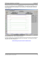
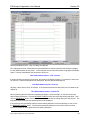
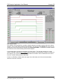
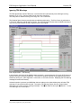
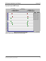
During data recording, the E84 Analysis application plots the acquired E84 Signal Stream on a timing
diagram graph in real-time and saves it to a temporary file on disk. During data upload via the E84 DLD,
the E84 Analysis application converts the logged data and saves it to a temporary file on disk. Data
analysis features are not available during Data Recording Mode (except for the real-time updates to the
timing diagram graph, when not in Long Term Recording mode). Recorded and uploaded data can be
analyzed using the Playback Analysis Mode described below.
Recorded Data File Structure
The recorded data file contains all user supplied test information, along with time-stamped data samples
for each signal state change that occurred during the recording session. Only those data samples that
contain a state change are logged to the data file. This provides a compressed file format to limit the size
requirements of the data file. If every sampled data point were stored (at the 1 kHz sample rate), the
storage requirements would be 4 kBytes for each second of recorded data. For a typical 3 minute test,
that would equate to a 720 kByte file. Saving only the signal state changes reduces this storage
requirement to under 100 bytes (for a typical load sequence). E84 Specification violations such as idle
noise will affect the storage requirements.
The compressed data file is expanded during Playback Analysis Mode to display the true 1 mSecond
sample data recorded by the E84 Recorder.
Starting and Stopping Data Recording
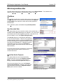
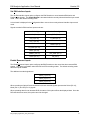
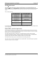
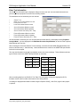
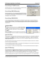
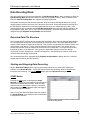
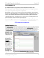
While in Data Record Mode (with Long Term Recording enabled or not), three option buttons are
available on the Graph Window. The START button initiates data recording, while the STOP button
terminates data recording. The UPLOAD DLD button opens the Upload DLD dialog box
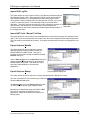
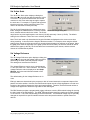
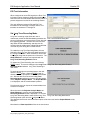
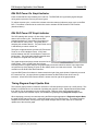
START Button
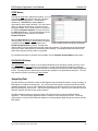
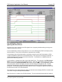
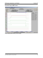
Pressing the Start button re-displayed the Graph
Window (to include the user supplied Test Information if
entered) and initiates data recording. Data recording
continues until the Stop button is pressed. Recorded
data is added to the timing diagram graph, and logged
to disk in a temporary data file.
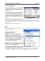
Note, if Long Term Recording Mode has been enabled,
the Graph Window is not displayed, and recorded data
is not plotted in real-time.
Data Recording Mode
E84_Analysis_Application_User_Manual.wpd
15