1
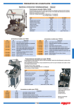
® Communication Systems, Inc. Wireless Table Radio AM and FM Radio plus Wireless TV Control MODEL: PDI-TR100 PDI-TR100 Table Radio User Manual CAUTION CAUTION: TO REDUCE THE RISK OF ELECTRIC SHOCK.DO NOT REMOVE COVER (OR BACK) NO USER SERVICEABLE PARTS INSIDE.REFER SERVICING TO QUALIFIED SERVICE PERSONNEL. CAUTION TO REDUCE THE RISK OF ELECTRIC SHOCK, DO NOT REMOVE COVER OR BACK. THERE ARE NO USER-SERVICEABLE PARTS INSIDE. REFER SERVICING TO QUALIFIED SERVICE PERSONNEL. TO REDUCE THE RISK OF FIRE OR ELECTRIC SHOCK, DO NOT EXPOSE THIS UNIT TO RAIN OR MOISTURE. FCC INFORMATION This equipment has been tested and found to comply with the limits for Class B digital devices, pursuant to Part 15 of the FCC Rules. These limits are designed to provide reasonable protection against harmful interference. This equipment generates, uses and can radiate radio frequency energy and, if not installed and used in accordance with the instructions, may cause harmful interference to radio communications. However, there is no guarantee that interference will not occur in a particular installation. If this equipment does cause harmful interference to radio or television reception, which can be determined by turning the equipment off and on, the user is encouraged to try to correct interference by one or more of the following measures: • Reorient or relocate the receiving antenna. • Increase the separation between the equipment and receiver. • Connect the equipment into an outlet on a circuit different from that to which the receiver is connected. • Consult the dealer or an experienced Radio/TV technician for help. This equipment complies with Part 15 of the FCC Rules. Operation is subject to the following conditions: • This equipment may not cause harmful interference. • This equipment must accept any interference received, including interference that may cause undesired operation. MODIFICATIONS Changes or modifications not expressly approved by the party responsible for compliance could void the user’s authority to operate the equipment. SERVICING User Servicing If your product is not operating correctly or exhibits a marked change in performance and you are unable to restore normal operation by following the detailed procedure in its operating instructions, do not attempt to service it yourself as opening or removing covers may expose you to dangerous voltage or other hazards. Refer all servicing to qualified service personnel. 2 Document: PD196-191R2.doc The lightning flash with arrow-head symbol within an equilateral triangle is intended to alert the user to the presence of uninsulated “dangerous voltage” within the unit’s enclosure that may be of sufficient magnitude to constitute a risk of electric shock. The exclamation point within an equilateral triangle is intended to alert the user to the presence of important operating and maintenance (servicing) instructions in the literature accompanying the unit. Damage Requiring Service Unplug this product from the wall outlet and refer servicing to qualified service personnel under the following conditions: • When the power supply cord or plug is damaged. • If liquid has been spilled, or objects have fallen into the product. • If the product has been exposed to rain or water. • If the product does not operate normally by following the operating instructions. Adjust only those controls that are covered by the operating instructions as an improper adjustment of other controls may result in damage and will often require extensive work by a qualified technician to restore the product to its normal operation. • If the product has been dropped or damaged in any way. • When the product exhibits a distinct change in performance which indicates a need for service. Replacement Parts When replacement parts are required, be sure the service technician has used replacement parts specified by the manufacturer or have the same characteristics as the original part. Unauthorized substitutions may result in fire, electric shock, or other hazards. Safety Check Upon completion of any service or repairs to this product, ask the service technician to perform safety checks to determine that the product is in safe operating conditions. CLEANING & DISINFECTING • • • • Unplug the radio before cleaning. Use a soft damp cloth to clean. Do not use harsh chemicals such as solvents. Wipe off water droplets from the cabinet as soon as possible as they may leave spots. DISCLAIMER The author and publisher have used their best efforts in preparing these instructions. PDI Communication Systems, Inc. make no representation or warranties with respect to the accuracy or completeness of the contents of this guide and specifically disclaim any implied warranties or merchantability or fitness for any particular purpose and shall in no event be liable for any loss of profit or any other damages. The information contained herein is believed accurate, but is not warranted and is subject to change without notice or obligation. COPYRIGHT PDI communication Systems, Inc. claims proprietary right to the material disclosed in these instructions and issues them for user information only and may not be used to manufacture anything shown herein. Copyright 2011 by PDI Communication System, Inc. PDI-TR100 Table Radio User Manual Document: PD196-191R2.doc IMPORTANT SAFETY INSTRUCTIONS 1. Read these instructions. 2. Keep these instructions. 3. Heed all warnings. 4. Follow all instructions. 5. Do not use this apparatus near water. 6. Clean only with dry cloth. 7. Do not block any ventilation openings. Install in accordance with the manufacturer’s instructions. 8. Do not install near any heat sources such as radiators, heat registers, stoves, or other apparatus (including amplifiers) that produce heat. 9. Do not defeat the safety purpose of the polarized or grounding-type plug. A polarized plug has two blades with one wider than the other. A grounding type plug has two blades and a third grounding prong. The wide blade or the third prong are provided for your safety. If the provided plug does not fit into your outlet, consult an electrician for replacement of the obsolete outlet. 10. Protect the power cord from being walked on or pinched particularly at plugs, convenience receptacles, and the point where they exit from the apparatus. 11. Only use attachments/accessories specified by the manufacturer. 12. User only with the cart, stand, tripod, bracket, or table specified by the manufacturer, or sold with the apparatus. When a cart is used, use caution when moving the cart/apparatus combination to avoid injury from tip-over. 13. Unplug this apparatus during lightning storms or when unused for long periods of time. 14. Refer all servicing to qualified service personnel. Servicing is required when the apparatus has been damaged in any way, such as power-supply cord or plug is damaged, liquid has been spilled or objects have fallen into the apparatus, the apparatus has been exposed to rain or moisture, does not operate normally, or has been dropped. 15. If an outside antenna or cable system is connected to this apparatus, be sure the antenna or cable system is grounded so as to provide some protection against voltage surges and built-up static charges. Section 810 of the National Electrical Code, ANSI/NFPA 70, provides information with respect to proper grounding of the mast and supporting structure, grounding of the lead-in wire to an antenna discharge unit, size of grounding conductors, location of antenna-discharge unit, connection to grounding electrodes, and requirements for the grounding electrode. See Figure A. NEC – NATIONAL ELECTRICAL CODE ANTENNA LEAD IN WIRE GROUND CLAMP ELECTRIC SERVICE EQUIPMENT ANTENNA DISCHARGE UNIT (NEC SECTION 810 – 20) GROUNDING CONDUCTORS (NEC SECTION 810 – 21) GROUND CLAMPS FIG. A POWER SERVICE GROUNDING ELECTRODE SYSTEM (NEC ART 250, PART H) NOTE: This reminder is provided to call the CATV system installer’s attention to article 820-40 of the NEC that provides guidelines for proper grounding and, in particular, specifies that the cable ground shall be connected to the grounding system of the building, as close to the point of cable entry as practical. 16. WARNING: To Reduce The Risk Of Fire Or Electrical Shock, Do Not Expose This Apparatus to Rain or Moisture. The apparatus shall not be exposed to dripping or splashing and that no objects filled with liquids, such as vases, shall be placed on the apparatus. 3 PDI-TR100 Table Radio User Manual Document: PD196-191R2.doc Package Contents Carefully unpack your Table Radio and verify that the following items are included. FM Antenna Table Radio Power Adapter ® on icati mun . Com ms, Inc te s y S o Radi ablioe T s ol s tr ad le on Wire and FM R ireless C AM T plus AM Antenna AAA Batteries VW EL: MOD 100 TR PDI- mber: ent Nu Docum 1.doc -191R PD196 User Manual Installing Location The PDI-TR100 table radio is designed to provide both AM/FM radio reception and also wireless Pairing Digital Interface control of PDI wall mounted hospital televisions.* Please keep these guidelines in mind when selecting a location. • Place the radio on a flat surface. • Do not use the radio in a damp location. • Locate the table radio in the same room as the TV if wireless connectivity is desired. • A location near the patient’s bed or chair side is preferred for easy operation. wireless Pairing Digital Interface * Note: PDI wall mounted television model must offer wireless connectivity to function. 4 PDI-TR100 Table Radio User Manual Document: PD196-191R2.doc Installing - continued Battery Installation Two AAA batteries are provided to keep the table radio’s clock running and backup the internal memory should power be interrupted. The batteries do not power the table radio or light the display. 1. Locate the CLOCK BATTERY cover on the back of the table radio. 2. Press the tab on the cover and remove. 3. Insert each of the AAA batteries provided into the battery compartment making certain to match the battery (+) and (-) polarities as shown. 4. Reinstall the CLOCK BATTERY cover making certain the tab snaps in place to secure the cover. WARNING: Do not expose the batteries to excessive heat such as sunshine, fire or the like. Antenna Installation FM ANTENNA 1. Connect the supplied FM antenna to the FM Antenna jack on the back of the radio. HEADPHONES C L O C K B A T T E R Y The table radio relies upon 2 externally connected antennas for signal. F M A N T E N N A S C A N P A I R C L O C K S E T D C 1 5 V 1 . 6 A A M A N T E N N A 2. Alternatively, an FM signal available on a CATV system cable can be connected. Contact your cable provider for assistance. AM ANTENNA 1. Connect the supplied AM antenna to the AM Antenna jack on the back of the radio. FM Antenna AM Antenna 5 PDI-TR100 Table Radio User Manual Document: PD196-191R2.doc Installing - continued Anti-Theft Lock HEADPHONES C L O C K B A T T E R Y C L O C K B A T T E R Y L O C K B A T T E R Y C A laptop cable lock (not supplied) can be attached to the back of the radio to deter theft. F M A N T E N N A P A I R S C A N C L O C K S E T D C 1 5 V 1 . 6 A A M A N T E N N A Lock Slot Power Adapter Installation HEADPHONES The radio is powered from an external power adapter. 1. Connect the Power Adapter plug into the DC power jack on the back cabinet. 2. Connect the body of the Power Adapter into an AC wall outlet. Headphone Connection For private listening the radio comes equipped with a rear mounted Headphone Jack. 1. Connect the headphones (not supplied) to the Headphone Jack. The Radio’s internal speakers will be muted. Radio sound should now play through the connected headphones. 2. Disconnect the headphones to restore sound to the Radio’s internal speakers. 6 F M A N T E N N A P A I R S C A N S E T C L O C K D C 1 5 V 1 . 6 A A M A N T E N N A HEADPHONES F M A N T E N N A P A I R C L O C K S E T S C A N D C 1 5 V 1 . 6 A A M A N T E N N A PDI-TR100 Table Radio User Manual Document: PD196-191R2.doc Programming Controls Three knobs control the functions of Volume, Mode, and Tuning. 1. VOLUME - Adjust volume. Push in and release to Mute sound. Push in again and release or rotate knob to un-Mute. 2. MODE - Place the radio in STANDBY, TV, FM, or AM mode. 3. TUNING - Tune AM, FM, and TV channels. In TV mode, Push in and release for Closed Captions. 2 1 3 DISPLAY The front display provides a considerable amount of information. A. MODE - Display active TV, FM, or AM mode. A TV C L IN K 12:00 AM B. ALARM - Icon visible when Alarm is enabled. C. LINK - Icon visible when radio is linked to a TV. 15 D. VOLUME - Volume level (0~30). E. BATTERY - Replace batteries when icon is visible. B D M01 G A E F F. MEMORY - Active memory channel (0~20). G. TIME / FREQUENCY - Displays current AM/FM frequency or time. 7 PDI-TR100 Table Radio User Manual Document: PD196-191R2.doc Programming - continued Setting the Clock The clock is set using the CLOCK SET button and the Tuning knob. Push in on the Tuning knob to advance through the clock settings. HEADPHONES CLOCK BATTERY 1. Place the radio in STANDBY mode. 2. Press and hold down the CLOCK SET button on the back of the radio until the Time Display Hours begins to blink. Release the button. FM ANTENNA PAIR CLOCK SET SCAN DC15V-1.6A AM ANTENNA 3. Turn the Tuning knob clockwise or counter clockwise to set the current hour. 4. Push in and release the Tuning knob until the minute display begins to blink. CLOCK SET Button 5. Turn the Tuning knob clockwise or counter clockwise to set the current minutes. 6. Push in and release the Tuning knob, turn it clockwise or counter clockwise to select 12 or 24 hour display format. 7. Push in and release the Tuning knob to exit. Searching for Radio Stations HEADPHONES 1. Turn the radio to the desired mode either FM or AM. 2. Press and hold down the Scan button on the back of the radio until the front frequency display begins to scan. The Memory indicator will index as the radio discovers active stations and reads them into memory. 3. Advance through the stored memory channels using the Tuning knob and check for stored stations. Note: If the radio does not discover expected stations, try to reorient the antenna for better reception and Scan again. C L O C K B A T T E R Y AM or FM radio stations can be manually tuned or scanned and stored into the radio’s channel memory. The radio’s channel memory is then tuned during normal listening. F M A N T E N N A P A I R S C A N S E T C L O C K D C 1 5 V 1 . 6 A A M A N T E N N A Scan Button FM 93.7 MHz 15 Memory Indicator M01 4. Alternately, press the Scan button until the Memory Indicator disappears and tune the radio manually. 8 PDI-TR100 Table Radio User Manual Document: PD196-191R2.doc Programming - continued Wireless Pairing to a Television PDI Television models that offer wireless capability can be linked to the table radio. Both remote control of the TV and TV sound are available through the table radio. Verify the PDI television model offers wireless connectivity by turning the TV On and then press and hold down the TV/ AV button on the TV for 6 seconds - a Wireless Audio menu will appear on compatible models. 1. Use a PDI programming remote control and enter the TV’s Setup menu and select Features. 2. In the Features menu, set Standby Power to Normal. 3. In the Features menu, also set Wireless Audio to Enabled. 4. On the TV press and hold down the TV/AV button for 6 seconds until the Wireless Audio menu appears. 5. In the Wireless Audio menu, set the Wireless Audio Status item to Wireless PDi. 6. Now, set the Radio to TV mode. The radio will remain in Pairing Mode for 180 seconds. If necessary re-enable Pairing Mode by depressing the Pair button for 5 seconds. ■ ■ ■ ■ ■ ■ ■ ■ ■ ■ ■ ■ Power On Caption Mode Inactive Power Off(h:mm) Bed A/B Caption Text Modes Digital Captions Digital Mode Time Setup Diagnostics Channel Up Power Off Channel to other Sources Power on ARC Mode Standby Power Wireless Audio Last Disabled A Disabled ▶ ▶ ▶ Disabled Enabled Last Normal Enabled Position: Exit: SETUP Next: Wireless Audio ■ Wireless Audio Status ■ Pair Wireless Audio ■ Clear Wireless Audio Device Position: Exit: SETUP Wireless PDi Next: HEADPHONES C L O C K B A T T E R Y 7. Press and hold down the Pair button on the back of the radio for 5 seconds until the word PAIR appears on the radio’s display. Features F M A N T E N N A P A I R S C A N C L O C K S E T D C 1 5 V 1 . 6 A A M A N T E N N A Pair Button 9 PDI-TR100 Table Radio User Manual Document: PD196-191R2.doc Programming - continued Wireless Pairing to a Television - continued 8. In the Wireless Audio menu, select Pair Wireless Audio. The TV will now search for available nearby wireless devices. Wireless Audio ■ Wireless Audio Status ■ Pair Wireless Audio ■ Clear Wireless Audio Device Position: Exit: SETUP 9. In the Wireless Device Listing menu, select the appropriate table radio device recently located, keeping in mind that more than one device may appear. NOTE: Listing of wireless devices may differ from those illustrated. Next: Wireless Device Listing Found the following nearby devices ■ TR100-01 ■ TR100-02 Position: Exit: SETUP 10.Enter the Passkey code 0, 0, 0, 0 for the table radio. Press the next arrow (Volume Up button) to continue. 944452C80F08 944452C80F09 Next: Wireless Device Passkey ■ Passkey 0 0 0 0 __ __ __ __ __ __ __ __ Exit: TV/AV 10 Wireless PDi Next: PDI-TR100 Table Radio User Manual Document: PD196-191R2.doc Programming - continued Wireless Pairing to a Television - continued 11.A success message will appear when the radio is paired with the TV. Press Volume up to continue. Wireless Device Passkey Wireless Device Paired Successfully Press to continue 12.Check for TV sound from the radio. 13.Adjust the Tuning knob on the radio. The TV displays Channel Numbers as the knob is rotated. Select the desired Channel. The TV should then change to the displayed channel. Next: Exit: TV/AV 14.Turn the Mode knob to Standby, AM, or FM. The TV should turn Off for all modes except when set to TV. Turn the Knob to TV - the TV should turn On. Wireless Audio Clearing a Wireless Paired Device A device that is linked to the radio can be disconnected. To disconnect the TV from the radio use the following procedure. ■ Wireless Audio Status ■ Pair Wireless Audio ■ Clear Wireless Audio Device Wireless PDi 1. Turn the radio to TV mode. 2. On the TV press and hold down the TV/ AV button for 6 seconds until the Wireless Audio menu appears. 3. In the Wireless Audio menu highlight Clear Wireless Audio Device. Press Volume up to select. Position: Exit: SETUP Next: Wireless Device Clearing Are you sure you would like to disconnect and unpair wireless device? 4. A confirmation screen will appear. Select Yes to disconnect the device. No Yes 5. Verify the radio is no longer linked to the TV. Exit: TV/AV Next: 11 PDI-TR100 Table Radio User Manual Document: PD196-191R2.doc Additional Settings Display Brightness Adjustment 1. Place the radio in STANDBY mode. 2. Push the Tuning Knob in for 3 seconds until the display changes to DIMMER ALARM. DIMMER ALARM HI OFF 3. Turn the Tuning Knob clockwise or counter clockwise to set the display brightness to either HI (high) , MI (medium), or LO (low). 4. Push the Tuning knob in to advance the selection to ALARM. 5. Turn the Tuning knob clockwise or counter clockwise to turn the ALARM On or Off. Setting the Alarm 6. To set the Alarm Time, turn the ALARM On and then press the Tuning Knob once to display the Alarm’s time. 7. Turn the Tuning knob clockwise or counter clockwise to set the current hour. 8. Push in on the Tuning knob until the minute display begins to blink. 9. Turn the Tuning knob clockwise or counter clockwise to set the current minutes. 10.Push in on the Tuning knob to exit. 11.Turn either the Volume or Tuning knob to silence the Alarm. Bass and Treble Adjustment 1. Place the radio in AM or FM mode. 2. Push the Tuning Knob in for 3 seconds until the display changes to BASS TREBLE. BASS TREBLE 0 -1 3. Turn the Tuning Knob clockwise or counter clockwise to set the Bass level (-3 ~ 3). 4. Push the Tuning Knob in to advance the selection to Treble. 5. Turn the Tuning Knob clockwise or counter clockwise to set the Treble level (-3 ~ 3). 6. Push in on the Tuning knob to exit. 12 PDI-TR100 Table Radio User Manual Document: PD196-191R2.doc Troubleshooting SYMPTOM Radio does not function. • • No Sound. • • • Table radio does not link or control TV. AM radio reception is weak. • • • • • • • • FM radio reception is weak. • • • • RESOLUTION Make certain the Power Adapter wired connector is inserted securely into the radio. Verify the Power Adapter is plugged fully into a powered AC wall outlet. Increase the Volume. Push in and release the Volume button and verify the radio sound is not muted. Disconnect Headphones if connected and recheck for sound. Verify that the TV is a PDI brand with wireless option. Verify the PDI television model offers wireless connectivity by turning the TV On and then press and hold down the TV/AV button for 6 seconds - a Wireless Audio menu will appear on compatible models. Verify the Table Radio is within 30 feet of the TV. Verify the external AM Antenna is connected. Re-scan for channels. If the radio does not discover expected stations, try to reorient the antenna for better reception and Scan again. Move the radio farther away form sources of interference such as fluorescent lights or other electronic equipment which generate electrical noise. The radio’s location may be in an area of weak AM signal coverage. Verify the external FM Wire Antenna is connected. Re-scan for channels. If the radio does not discover expected stations, try to reorient the antenna for better reception and Scan again. The radio’s location may be in an area of weak FM signal coverage. Customer Service For additional help in resolving problems, contact PDI Customer Service. PDI Communication Systems, Inc. 40 Greenwood Lane Springboro, Ohio 45066 PH: 800-628-9870 FX: 937-743-5664 13 PDI-TR100 Table Radio User Manual Document: PD196-191R2.doc SPECIFICATIONS* MODEL:PDI-TR100 FM/AM Tuner: Yes FM Frequency Range: 87.5 ~ 108 Mhz AM Frequency Range: 530 ~ 1700 Khz Wireless Audio Output: Yes Backlit Display: Yes TV Channel Selection: Yes, with compatible TV Models Only Alarm Clock:Yes Speaker Size: 3 inch Full Range Power Adaptor Rating: 15 Vdc, 1.6 A Input: 15 Vdc, 1.6 A Power Maximum: 8 Watts Power Standby: less than 1 Watt Operating Temperature: For moderate climates Storage Temperature: -4° F to +113° F Dimensions: 4.7H x 5.5D x 7.1W Inch Weight:2.75 lbs. *Specifications are believed accurate, but are not warranted, and are subject to change without notice or obligation. 14 PDI-TR100 Table Radio User Manual Document: PD196-191R2.doc PDI Limited Warranty PDI Communication Systems (PDI) warrants this product, except as set forth below, ONLY TO THE ORIGINAL PURCHASER to be FREE FROM DEFECTIVE MATERIAL AND WORKMANSHIP from the date of original purchase for a period of 2 years for parts and 2 years for labor (“The Warranty Period”). THIS LIMITED WARRANTY IS VALID ONLY IN THE FIFTY (50) UNITED STATES, THE DISTRICT OF COLUMBIA, AND CANADA. If this product is found to be defective, PDI will repair or replace defective parts at no charge to the original owner during the warranty period. Such repair and replacement services shall be rendered by PDI or a PDI Authorized Servicer during normal business hours. Parts used for replacement or repair are warranted only for the remainder of the Warranty Period. To return a product for service please obtain a Return Material Authorization (RMA) from PDI. Products returned without a RMA will not be serviced. WHAT IS NOT COVERED This limited warranty provided by PDI does NOT cover: 1. Product which has been subject to abuse, accident, alteration, modification, tampering, negligence, misuse, faulty installation, lack of reasonable care, or if affixed to any attachment not specified for the product; 2. Product that has either the model number or serial number altered, tampered with, defaced or removed; 3. Initial installation and removal for repair; 4. Operational adjustments covered in the Owner’s Manual, normal maintenance, and cleaning; 5. Damage that occurs in shipment, due to act of God, and cosmetic damage; 6. Signal reception problems and failures due to line power surge; 7. The cost for shipping the product to PDI’s service center; 8. Accessories; 9. Batteries; There are no expressed warranties except as listed above. THE DURATION OF ANY IMPLIED WARRANTIES, INCLUDING THE IMPLIED WARRANTY OF MERCHANTABILITY, IS LIMITED TO THE DURATION OF THE EXPRESSED WARRANTY HEREIN. PDI SHALL NOT BE LIABLE FOR THE LOSS OF USE OF THE PRODUCT, INCONVENIENCE, LOSS OR ANY OTHER DAMAGES, WHETHER DIRECT, INCIDENTAL OR CONSEQUENTIAL RESULTING FROM THE USE OF THIS PRODUCT, OR ARISING OUT OF ANY BREACH OF THIS WARRANTY. ALL EXPRESSED AND IMPLIED WARRANTIES, INCLUDING THE WARRANTIES OF MERCHANTABILITY AND FITNESS FOR A PARTICULAR PURPOSE, ARE LIMITED TO THE WARRANTY PERIOD SET FORTH ABOVE. Some states do not allow the exclusion of incidental or consequential damages or limitations on how long an implied warranty lasts, so these limitations or exclusions may not apply to you. This warranty gives you specific legal rights and you may also have other rights which vary from state to state. Refurbished products carry a separate warranty. This warranty does not apply. For details of refurbished product warranty, please refer to the refurbished product warranty information packaged with each refurbished product. PDI Communication Systems, Inc. 40 Greenwood Lane Springboro, Ohio 45066 PH: 800-628-9870 FX: 937-743-5664 15 ® Communication Systems, Inc. 40 Greenwood Lane Springboro, Ohio 45066 USA MODEL: PDI-TR100 User Manual Document Number: PD196-191R2.doc