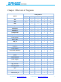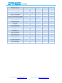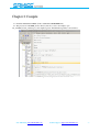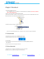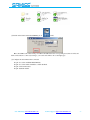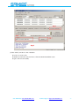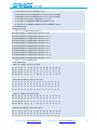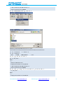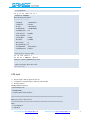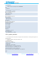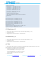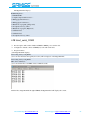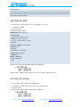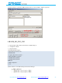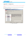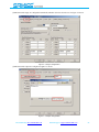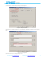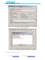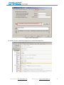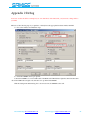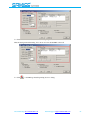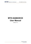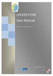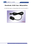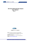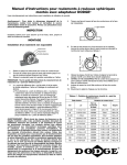
1
MBS
MBS-SAM9G15/9G25
/9G25
/9G35/9X25/9X35
MDK User Manual
:
:
Rev V1.1 Date 2012.05.15
Embest Info&Tech Co., LTD.
Revision History
Rev
Date
Description
By
1.0
2012-03-07
Initial version
huangyin
1.1
2012-5-15
Examples added
This document copyright belongs to embest technology Co., LTD. © 2012
Sales &Marketing: [email protected]
huangyin
Technical support: [email protected]
Catalog
Chapter 1 The List of Programs .................................................................................................... - 1 Chapter 2 Compile ........................................................................................................................ - 3 Chapter 3 Download ..................................................................................................................... - 4 3.1 Auto download ........................................................................................................................................... - 4 3.2 Manual download ...................................................................................................................................... - 4 -
Chapter 4 Programs Testing .......................................................................................................... - 9 4.1 ADC_adc10 .......................................................................................................................................... - 9 4.2 CAN ........................................................................................................................................................... - 9 4.3 DMA ........................................................................................................................................................ - 10 4.4 EEPROM ................................................................................................................................................. - 12 4.5 EMAC0 (eth0) test................................................................................................................................... - 12 4.6 EMAC1 (eth1) test................................................................................................................................... - 13 4.7 getting-started .......................................................................................................................................... - 14 4.8 hsmci_multimedia_card ........................................................................................................................... - 14 4.9 hsmci_sdcard ........................................................................................................................................... - 15 4.10 hsmci_sdio ............................................................................................................................................. - 17 4.11 LCD_4.3 ................................................................................................................................................ - 19 4.12 LCD_7.0 ................................................................................................................................................ - 19 4.13 LCD_10.2 .............................................................................................................................................. - 19 4.14 periph_protect ........................................................................................................................................ - 19 4.15 pmc_clock_switching ............................................................................................................................ - 20 4.16 PWM...................................................................................................................................................... - 21 4.17 qtouch .................................................................................................................................................... - 21 4.18 Rs485_loopback .................................................................................................................................... - 22 4.19 Rs485_twoport....................................................................................................................................... - 22 4.20 smc_nandflash ....................................................................................................................................... - 22 4.21 spi_serialflash ........................................................................................................................................ - 24 4.22 ssc_dma_audio ....................................................................................................................................... - 24 4.23 sysc ........................................................................................................................................................ - 26 4.24 tc_capture_waveform ............................................................................................................................ - 27 4.25 Touchscreen_4.3 .................................................................................................................................... - 28 4.26 Touchscreen_7.0 .................................................................................................................................... - 28 4.27 TWI ........................................................................................................................................................ - 28 4.28 Usart_serial_COM0 ............................................................................................................................... - 29 4.29 Usart_serial_COM3 ............................................................................................................................... - 30 4.30 Usart_hw_handshaking_COM3............................................................................................................. - 30 4.31 USB_Audio ........................................................................................................................................... - 31 4.32 USB_CDC_serial................................................................................................................................... - 31 4.33 USB_core............................................................................................................................................... - 31 4.34 USB_HID_mouse .................................................................................................................................. - 32 4.35 USB_HID_keyboard.............................................................................................................................. - 32 -
Sales &Marketing: [email protected]
Technical support: [email protected]
4.36 USB_HID_MSD .................................................................................................................................... - 33 4.37 USB_HID_transfer ................................................................................................................................ - 33 4.38 USB_IAD_CDC_CDC .......................................................................................................................... - 34 4.39 USB_IAD_CDC_HID ........................................................................................................................... - 35 4.40 USB_IAD_CDC_MSD.......................................................................................................................... - 35 4.41 USB_massstorage .................................................................................................................................. - 36 -
Appendix 1 Configuration ........................................................................................................... - 37 Appendix 2 Debug ...................................................................................................................... - 42 Appendix 3 Contact Us ............................................................................................................... - 44 -
Sales &Marketing: [email protected]
Technical support: [email protected]
Chapter 1 The List of Programs
ARM9 products
projects
9G15
9G25
9G35
9x25
9x35
adc
√
√
√
√
√
can
×
×
×
√
√
dma
√
√
√
√
√
eeprom
√
√
√
√
√
Emac(eth0)
×
√
√
√
√
Emac(eth1)
×
×
×
√
×
getting-started
√
√
√
√
√
Hsmci_multimedia_card
√
√
√
√
√
Hsmci_sdcard
√
√
√
√
√
Hsmci_sdio
√
√
√
√
√
LCD_4.3
√
×
√
×
√
LCD_7.0
√
×
√
×
√
LCD_10.2
√
×
√
×
√
periph_protect
√
√
√
√
√
pmc_clock_switching
√
√
√
√
√
pwm
√
√
√
√
√
qtouch
√
√
√
√
√
Rs485_loopback
√
√
√
√
√
Rs485_twoport
√
√
√
√
√
Smc_nandflash
√
√
√
√
√
Spi_serialflash
√
√
√
√
√
Ssc_dma_audio
√
√
√
√
√
sysc
√
√
√
√
√
tc_capture_waveform
√
√
√
√
√
Touchscreen_4.3
√
×
√
×
√
Sales &Marketing: [email protected]
Technical support: [email protected]
-1-
Touchscreen_7.0
√
×
√
×
√
twi
√
√
√
√
√
Usart_serial_COM0
√
√
√
√
√
Usart_serial_COM3
×
√
×
√
×
Usart_hw_handshaking_COM3
×
√
×
√
×
usb_audio_looprec
√
√
√
√
√
usb_cdc_serial
√
√
√
√
√
usb_core
√
√
√
√
√
usb_hid_keyboard
√
√
√
√
√
usb_hid_mouse
√
√
√
√
√
usb_hid_msd
√
√
√
√
√
usb_hid_transfer
√
√
√
√
√
usb_iad_cdc_cdc
√
√
√
√
√
usb_iad_cdc_hid
√
√
√
√
√
usb_iad_cdc_msd
√
√
√
√
√
usb_masstorage
√
√
√
√
√
Sales &Marketing: [email protected]
Technical support: [email protected]
-2-
Chapter 2 Compile
(1)Install the keil RealView MDK, (in 04-tools\RealView MDK\MDK4.22a)
(2)The projects are in 05-MDK_Source directory. We choose adc as an example: open
adc_adc10\Project\adc_adc10.uvproj, and compile it(project-rebuild all target files) as shown below:
Figure 1-1 compilation
Sales &Marketing: [email protected]
Technical support: [email protected]
-3-
Chapter 3 Download
(1) Install the SAM-BA(in 03-Tools\);
Note: If SAM-BA 2.10 or less is installed, we should uninstall it before installation.(uninstall both SAM-BA
software and board USB driver)
(2) Power on and connect the board and PC with micro USB;
(3) Turn off the the number 1 and nuber 2 switch of SW, and reset the board. And we should install the driver at the
first time. The driver can be found under its installation directory:
(4) Check it in the device manager, it should be like this:
Now we can download the program in auto or manual way. Auto download is strongly recommended.
3.1 Auto download
1) install the sam-ba( in detals to 03-tools\SAM-BA\sam-ba install)
2) disable the JP3,and reset the board, you can see the flag as follows:
3) connet the JP3
4) open the package of 01_audio\download.and click the file of SAM9G45_MDK_nandflash.bat,
let it download
5) reset the board,you can see the output of the board
3.2 Manual download
(1) Take 9G15-adc as an example, after building the program, open the folder
05_MDK_Source\adc_adc10\Download\9g15, it should be like this:
Sales &Marketing: [email protected]
Technical support: [email protected]
-4-
(2) Switch on the SW-2 and run the SAM-BA_V2.11
on PC:
Here, the COM8 is the virtual serial port COM of the USB. Select the corresponding board, here is 9G15, and
click connect button to connect.(according to your own board’s kind to choose the right type)
(3) Configure the environment when connected:
Step1 choose the serialflash AT25/AT26 tab;
Step2 choose the enable serialflash to enable dataflash;
Step3 click execute button;
Step4 dataflash enabled.
:
:
:
:
Sales &Marketing: [email protected]
Technical support: [email protected]
-5-
(4) After enabled, send the boot file of dataflash:
Step1: choose send boot file;
Step2:click execute button and select the boot file at91sam9x5ek-dataflashboot.bin;
Step3:boot file sent successfully.
Sales &Marketing: [email protected]
Technical support: [email protected]
-6-
Sales &Marketing: [email protected]
Technical support: [email protected]
-7-
(5) Send the image file ddram.bin:
Step1:select ddram.bin;
Step2:enter the download address 0x8400;
Step3:send file;
Step4:download successfully.
Sales &Marketing: [email protected]
Technical support: [email protected]
-8-
Chapter 4 Programs Testing
4.1 ADC_adc10
Test description: This program describes how to use the function of ADC.
Configuration: default
Test phenomenon:
The HyperTerminal will show the information as below:
-- ADC12 Example 2.0 --- SAM9XX5-EK
-- Compiled: Mar 27 2012 17:47:23 -=================================
- d: DMA Enable/Disable
- s: Channel sequence switch
- 0, 1, 2,
3: TRIGGER mode:
SW EXT Periodic Continuous
Refresh slow --> fast ....
=================================
= DMA: Enabled; Trigger mode: 0
= Sequence: 09 00 02
=================================
Vols(mV): #09:1400 #00:2322 #02:0509
4.2 CAN
Test description: This program shows how to transform USB to RS-232 serial port.
Configuration: default. disconnect JP9. connect USART0 with serial cable as DBGU, connect J18 and J19
Test phenomenon:
the HyperTerminal displays:
-- CAN Example 2.0 --- SAM9XX5-EK
-- Compiled: May 3 2012 09:12:59 -- Test start, DBGU not available now
-I- 0: 210000
- CAN0 Sync OK
-I- 1: 210000
- CAN1 Sync OK
-I- 0:20a00002
Sales &Marketing: [email protected]
Technical support: [email protected]
-9-
-I- 1: a00060
-I- 0:20a00006
-I- 1: a00060
-I- 1:40a00040
- CAN0.1: Simple test data received
- CAN0.2: Messages to 1 Mailbox received
-I- 0: a0000e
- CAN0.3: Messages to 1 Mailbox(OVR) received
-I- 1:20a00060
-I- 0: a0001e
- CAN1.5: Remote requested data received
-I- 1:20a00062
-I- 0: a0007e
-I- 1:20a00066
-I- 0: a0007e
-I- 0:40a0005e
- CAN1.1: Simple test data received
- CAN1.2: Messages to 1 Mailbox received
-I- 1: a0006e
- CAN1.3: Messages to 1 Mailbox(OVR) received
-I- 0:20a0007e
-I- 1: a0007e
- CAN0.5: Remote requested data received
-I- 0: 10007e
-I- 1: 10007e
4.3 DMA
Test description: This program describes the function of DMA
Configuration: default
Test phenomenon:
The HyperTerminal will show
-- DMA Example 2.0 --- SAM9XX5-EK
-- Compiled: Mar 27 2012 17:50:19 -Menu :
------ 1-9, A, B: Programming DMAC for Multiple Buffer Transfers
1: Single Buffer or Last buffer of a multiple buffer transfer
2: Multi Buffer transfer with contiguous DADDR
3: Multi Buffer transfer with contiguous SADDR
4: Multi Buffer transfer with LLI support
5: Multi Buffer transfer with DADDR reloaded
Sales &Marketing: [email protected]
Technical support: [email protected]
- 10 -
6: Multi Buffer transfer with SADDR reloaded
7: Multi Buffer transfer with BTSIZE reloaded and contiguous DADDR
8: Multi Buffer transfer with BTSIZE reloaded and contiguous SADDR
9: Automatic mode channel is stalling BTsize is reloaded
A: Automatic mode BTSIZE, SADDR and DADDR reloaded
B: Automatic mode BTSIZE, SADDR reloaded and DADDR contiguous
- s: Start DMA transfer
- h: Display this menu
Choose 1~9, A, Multiple Buffer Transfer:
Programming DMAC for Multiple Buffer Transfers in row 1
Programming DMAC for Multiple Buffer Transfers in row 2
Programming DMAC for Multiple Buffer Transfers in row 3
Programming DMAC for Multiple Buffer Transfers in row 4
Programming DMAC for Multiple Buffer Transfers in row 5
Programming DMAC for Multiple Buffer Transfers in row 6
Programming DMAC for Multiple Buffer Transfers in row 7
Programming DMAC for Multiple Buffer Transfers in row 8
Programming DMAC for Multiple Buffer Transfers in row 9
Programming DMAC for Multiple Buffer Transfers in row 10
Programming DMAC for Multiple Buffer Transfers in row 11
Choose s, start the DMA transfer:
-I- Start DMA transfer
-I- The Source Buffer content before transfer
00 01 02 03 04 05 06 07 08 09 0a 0b 0c 0d 0e 0f
00 02 04 06 08 0a 0c 0e 10 12 14 16 18 1a 1c 1e
00 03 06 09 0c 0f 12 15 18 1b 1e 21 24 27 2a 2d
00 04 08 0c 10 14 18 1c 20 24 28 2c 30 34 38 3c
-I- The Destination Buffer content before transfer
5a 5a 5a 5a 5a 5a 5a 5a 5a 5a 5a
5a 5a 5a 5a 5a 5a 5a 5a 5a 5a 5a
5a 5a 5a 5a 5a 5a 5a 5a 5a 5a 5a
5a 5a 5a 5a 5a 5a 5a 5a 5a 5a 5a
-I- The Source Buffer content after transfer
00 01 02 03 04 05 06 07 08
00 02 04 06 08 0a 0c 0e 10
00 03 06 09 0c 0f 12 15 18
00 04 08 0c 10 14 18 1c 20
09
12
1b
24
0a
14
1e
28
5a
5a
5a
5a
0b
16
21
2c
5a
5a
5a
5a
0c
18
24
30
5a
5a
5a
5a
0d
1a
27
34
5a
5a
5a
5a
5a
5a
5a
5a
0e 0f
1c 1e
2a 2d
38 3c
-I- The Destination Buffer content after transfer
00 01 02 03 00 01 02 03 00 01 02 03 00 01 02 03
00 01 02 03 00 01 02 03 00 01 02 03 5a 5a 5a 5a
5a 5a 5a 5a 5a 5a 5a 5a 5a 5a 5a 5a 5a 5a 5a 5a
Sales &Marketing: [email protected]
Technical support: [email protected]
- 11 -
5a 5a 5a 5a 5a 5a 5a 5a 5a 5a 5a 5a 5a 5a 5a 5a
Done
4.4 EEPROM
Test description: This program tests the EEPROM module.
Configuration: default
Test phenomenon:
-- EEPROM Example 2.0 --- SAM9XX5-EK
-- Compiled: Mar 6 2012 10:42:02 --I- Filling page #0 with zeroes ...
-I- Filling page #1 with zeroes ...
-I- Read/write on page #0 (polling mode)
-I- 0 comparison error(s) found
-I- Read/write on page #1 (IRQ mode)
-I- Callback fired !
-I- Callback fired !
-I- 0 comparison error(s) found
4.5 EMAC0 (eth0) test
Test description: This routine tests the respond to the ping command issued by the PC through the Ethernet
MAC (EMAC) interface and onboard network transceiver.
Configuration: default. Connect the board to the net (if the board is connected to the PC directly, we must
use crossover cable).
Test phenomenon:
the HyperTerminal displays:
-- EMAC Example 2.0 --- SAM9XX5-EK
-- Compiled: May 3 2012 10:31:32 --- MAC 0:45:56:78:9a:bc
-- IP 192.168.2.115
-I- ** Valid PHY Found: 0
Open command window, and input” ping 192.168.2.115”.
Sales &Marketing: [email protected]
Technical support: [email protected]
- 12 -
Test OK!
4.6 EMAC1 (eth1) test
Test description: This routine tests the respond to the ping command issued by the PC through the Ethernet
MAC (EMAC) interface and onboard network transceiver.
Configuration: default. Connect the board to the net (if the board is connected to the PC directly, we must
use crossover cable).
Test phenomenon:
the HyperTerminal displays:
-- EMAC Example 2.0 --- SAM9XX5-EK
-- Compiled: May 3 2012 10:31:32 --- MAC 0:45:56:78:9a:bc
-- IP 192.168.2.115
-I- ** Valid PHY Found: 0
Open command window, and input” ping 192.168.2.115”.
Test OK!
Sales &Marketing: [email protected]
Technical support: [email protected]
- 13 -
4.7 getting-started
Test description: This program shows the blink of LEDs
Configuration: default
Test phenomenon:
The D1 and D2 blink alternately. On the HyperTerminal, enter 1 to control D1, and enter 2 to control D2.
4.8 hsmci_multimedia_card
Test description: This program describes the identification, initialization and function testing of SD card.
Configuration: default.
Note: SD and MicroSD cards are needed. Insert the card after the HyperTerminal shows the message.
Test phenomenon:
The HyperTerminal will show:
-I- I cache is already enabled.
-- Basic MultiMedia Card Project 2.0 --- SAM9XX5-EK
-- Compiled: Mar 28 2012 14:26:08 --I- Cannot check if SD card is write-protected
Enter "1": the main menu
==========================================
-!- MCK is 133MHz
-!- Buffer@2000b748,size 0x400000
# i,I
: Re-initialize card
#t
: Disk R/W/Verify test
#T
: Disk performance test
#p
: Change number of blocks in one access for test
#m
: Change MCI interface used
Enter "m", choose the card: MCI0 refers to microSD, and MCI1 refers to SD. Take MCI1 as an example.
When card is chosen, it will be identified and initialized, we can get the information through the HyperTerminal:
==========================================
-I- SdMmcIdentify.Cmd5: 3
-I- SD MEM
-I- Card Type 2, CSD_STRUCTURE 0
-W- SD 4-bit mode
-I- HS Not Supported in SD Rev 0x0
-I- Set SD/MMC clock to 22222K
-I- SD/MMC card initialization successful
-I- MEM Card OK, size: 123 MB, 246016 * 512B
-I- ======= CID =======-I- ===================
Sales &Marketing: [email protected]
Technical support: [email protected]
- 14 -
-I- .MID Manufacturer ID
03
……
Enter "1" again, test SD as the same way:
Enter "i" or "I", initialize the SD card.
Enter "t", test read and write functions of SD
==========================================
-!- Test code: 1.clr, 2.wr, 3.rd
-I- Testing block [239128 - 246015] ...All block tested!
Enter T:
==========================================
-I- Performance test, size 4096K, Multi 8192, MCK 133MHz
-I- Read by Multi block, size 512
-I- Write by Multi block, size 512
--- Write test .. Done, Bad 0, Speed 2820K
--- Read test .. Done, Bad 0, Speed 10131K
--- Data verify .. OK
Enter p:
-!- Performance Multi set to 1
-!- Performance Multi set to 2
-!- Performance Multi set to 4
-!- Performance Multi set to 8
-!- Performance Multi set to 16
-!- Performance Multi set to 32
-!- Performance Multi set to 64
-!- Performance Multi set to 128
-!- Performance Multi set to 256
-!- Performance Multi set to 512
-!- Performance Multi set to 1024
-!- Performance Multi set to 2048
-!- Performance Multi set to 4096
-!- Performance Multi set to 8192
Testing succeed
4.9 hsmci_sdcard
Test description: This program tests the SD module.
Configuration: default; insert the SD card in the slot
Test phenomenon:
-- Basic HSMCI SD/MMC Example 2.0 --- SAM9XX5-EK
-- Compiled: Mar 21 2012 16:45:22 --I- Cannot check if SD card is write-protected
-- Please insert a card
SD
插入 卡后:
Sales &Marketing: [email protected]
Technical support: [email protected]
- 15 -
==========================================
-I- SdMmcIdentify.Cmd5: 3
-E- Acmd41.cmd55:3
-E- SdMmcIdentify.Cmd1: 3
-E- SD_Init.Identify: 5
-I- SdMmcIdentify.Cmd5: 3
-I- SD MEM
-I- Card Type 2, CSD_STRUCTURE 0
-W- SD 4-bit mode
-I- HS Not Supported in SD Rev 0x0
-I- Set SD/MMC clock to 22222K
-I- SD/MMC card initialization successful
-I- Card size: 123 MB, 246016 * 512B
-I- ======= CID =======-I- ===================
-I- .MID Manufacturer ID
03
-I- .CBX Card/BGA (eMMC)
3
-I- .OID OEM/Application ID (SD)
SD
-I- .OID OEM/Application ID (MMC)
44
-I- .PNM Product name (SD)
SD128
-I- .PNM Product name (MMC)
SD128€
-I- .PRV Product revision (SD)
80
-I- .PRV Product revision (MMC)
90
-I- .PSN Product serial number (SD) 90182858
-I- .PSN Product serial number (MMC) 18285800
-I- .MDT Manufacturing date (SD)
2006/11
-I- .MDT Manufacturing date (MMC)
2003/11
-I- .CRC checksum
49
-I- ======== CSD ========-I- ===================
-I- .CSD_STRUCTURE
0x0
-I- .SPEC_VERS (eMMC) 0x0
-I- .TAAC
0x26
-I- .NSAC
0x0
-I- .TRAN_SPEED
0x32
-I- .CCC
0x5F5
-I- .READ_BL_LEN
0x9
-I- .READ_BL_PARTIAL
0x1
-I- .WRITE_BLK_MISALIGN 0x0
-I- .READ_BLK_MISALIGN 0x0
-I- .DSR_IMP
0x0
-I- .C_SIZE
0xF03
-I- .C_SIZE_HC
0xFEFA
-I- .VDD_R_CURR_MIN
0x7
-I- .VDD_R_CURR_MAX
0x6
-I- .VDD_W_CURR_MIN
0x7
Sales &Marketing: [email protected]
Technical support: [email protected]
- 16 -
-I-I-I-I-I-I-I-I-I-I-I-I-I-I-I-I-I-I-I-I-I-I-
.VDD_W_CURR_MAX
0x6
.C_SIZE_MULT
0x4
.ERASE_BLK_EN
0x1
.SECTOR_SIZE
0x1F
.WP_GRP_SIZE
0x7F
.WP_GRP_ENABLE
0x1
.R2W_FACTOR
0x4
.WRITE_BL_LEN
0x9
.WRITE_BL_PARTIAL 0x0
.FILE_FORMAT_GRP
0x0
.COPY
0x1
.PERM_WRITE_PROTECT 0x0
.TMP_WRITE_PROTECT 0x0
.FILE_FORMAT
0x0
.ECC (MMC)
0x0
.CRC
0x5A
.MULT
0x40
.BLOCKNR
0x3C100
.BLOCKNR_HC
0x3FBEC00
.BLOCK_LEN
0x200
-TOTAL_SIZE
0x7820000
-TOTAL_SIZE_HC
0xF7D80000
==========================================
-!- MCI 1, code: 1.clr, 2.wr, 3.rd
-I- Testing block [246000 - 246015] ...All block tested!
4.10 hsmci_sdio
Test description: This program tests the SDIO module of SD
Configuration: default; insert the SDIO in the SD slot
Test phenomenon: the HyperTerminal displays:
-- MSMCI SDIO Example 2.0 --- SAM9XX5-EK
-- Compiled: Apr 17 2012 15:41:54 --I- Cannot check if SD card is write-protected
-I- SDIO
-I- Card Type 8, CSD_STRUCTURE 0
-I- HS Mode not supported by SDIO
-I- Set SD/MMC clock to 33333K
-I- SD/MMC card initialization successful
-I- ** SDIO ONLY card
-I- ====== CCCR ======
-I- .SDIO
01
Sales &Marketing: [email protected]
Technical support: [email protected]
- 17 -
-I- .CCCR
01
-I- .SD
01
-I- .IOE
00
-I- .IOR
02
-I- .IEN
00
-I- .INT
0
-I- .CD
0
-I- .SCSI
0
-I- .ECSI
0
-I- .BUS_WIDTH 0
-I- .4BLS
0
-I- .LSC
0
-I- .E4MI
0
-I- .S4MI
0
-I- .SBS
0
-I- .SRW
0
-I- .SMB
1
-I- .SDC
0
-I- .CIS_PTR
001000
-I- .BR
0
-I- .BS
0
-I- .DF
0
-I- .FS
0
-I- .EX
0
-I- .EXM
0
-I- .RF
0
-I- .RFM
0
-I- .FN0_SIZE 0(0000)
-I- .EMPC
0
-I- .SMPC
0
-I- .EHS
0
-I- .SHS
0
-I- ==== CISTPL_MANFID ====
-I- ._MANF 03BB
-I- ._CARD 0000
-I- == CISTPL_FUNCE Fun0 ==
-I- ._FN0_BLK_SIZE 512(0x0200)
-I- ._MAX_TRAN_SPEED 5A
==========================================
R/W Direct test:
CIA:
-I- buffer 20: .. .. .. ..
0: 11 01 00 02 00 00 00 00 02 00 10 00 00 00 00 00
Sales &Marketing: [email protected]
Technical support: [email protected]
- 18 -
10: 00 00 00 00
Write 0x03 to IEN(CIA.4): rc 0
IEN After Write:0x03
-- test OK
R/W Extended test:
Dump CIA:
-I- buffer 20: .. .. .. ..
0: 11 01 00 02 00 00 00 00 02 00 10 00 00 00 00 00
10: 00 00 00 00
Modify Some R/W bytes (2,4) for FN0 and write:
CIA after write:
-I- buffer 20: .. .. .. ..
0: 11 01 02 02 02 00 00 00 02 00 10 00 00 00 00 00
10: 00 00 00 00
-- test OK
4.11 LCD_4.3
Test description: This program tests the display of the LCD module.(including 4.3", 7.0", 10.2")
Configuration: default
Test phenomenon: the LCD displays pictures
4.12 LCD_7.0
Test description: This program tests the display of the LCD module.(including 4.3", 7.0", 10.2")
Configuration: default
Test phenomenon: the LCD displays pictures
4.13 LCD_10.2
Test description: This program tests the display of the LCD module.(including 4.3", 7.0", 10.2")
Configuration: default
Test phenomenon: the LCD displays pictures
4.14 periph_protect
Test description: This program shows how to prevent programs from interfering with the PIO controller.
Configuration: default
Test phenomenon:
The HyperTerminal displays:
-- Peripheral Protect Example 2.0 --- SAM9XX5-EK
Sales &Marketing: [email protected]
Technical support: [email protected]
- 19 -
-- Compiled: Apr 6 2012 11:45:15 -Enter 'l' to enable Write Protect and enter 'u' to disable Write Protect.
Select the register to be written by a value(0x12345678).
0 : PIO Enable Register
(0x0000)
1 : PIO Disable Register
(0x0004)
2 : PIO Output Enable Register
(0x0010)
3 : PIO Output Disable Register
(0x0014)
4 : PIO Input Filter Enable Register (0x0020)
5 : PIO Input Filter Disable Register (0x0024)
6 : PIO Multi-driver Enable Register (0x0050)
7 : PIO Multi-driver Disable Register (0x0054)
8 : PIO Pull Up Disable Register
(0x0060)
9 : PIO Pull Up Enable Register
(0x0064)
a : PIO Peripheral ABCD Select Register 1
(0x0070)
b : PIO Peripheral ABCD Select Register 2
(0x0074)
c : PIO Output Write Enable Register (0x00A0)
d : PIO Output Write Disable Register (0x00A4)
e : PIO Pad Pull Down Disable Register
(0x0090)
f : PIO Pad Pull Down Enable Register (0x0094)
Press "1"
No write protect violation is detected.
Press "u"
The Write Protect is disabled.
4.15 pmc_clock_switching
Test description: This program shows how to switch system clock(PLLA, UPLL, SLCK, MAINCK).
Configuration: default; baud rate: 1200; debug in SRAM mode only
Test phenomenon:
(1) the HyperTerminal displays:
** Switch to 1200 bps for DBG **
-- PMC Clock Switching example 2.0 --- SAM9XX5-EK
-- Compiled: Apr 17 2012 15:13:31 ---- Current PMC clock from lowlevel pmc configuration --The slow clock source is internal 32 kHz RC oscillator
PLLA clock is 800 MHz
PLLA clock is the source of Master clock
MCK Master Clock is prescaler output clock divided by 3
-I- Select main clock as the master clock
-I- Please measure the clock on PCK to make sure it is 12000000 Hz...
Sales &Marketing: [email protected]
Technical support: [email protected]
- 20 -
-I- Press ` to switch next clock configuration...
Press "`" to switch system clock:
-I- Select PLLA clock as the master clock
-I- Please measure the clock on PCK to make sure it is 12500000 Hz...
-I- Press ` to switch next clock configuration...
Press "`" to switch system clock:
-I- Select UTMI PLL clock as the master clock
-I- Please measure the clock on PCK to make sure it is 7500000 Hz...
-I- Press ` to switch next clock configuration...
Press "`" to switch system clock:
-I- Switch the XTAL 32K crystal oscillator to be the source of the slow clock
-I- Please measure the clock on PCK to make sure it is 32768 Hz...
-I- Debuging in EWARM IAR C_SPY, the JLINK will disconnect on some PC!
-I- Press ` to switch next clock configuration...
4.16 PWM
Test description: This program tests the PWM module.
Configuration: default
Test phenomenon:
(1) Connect pin18 of J22 to pin6 of J23, the D13 blinks at the frequency of f1;
(2) Connect pin17 of J22 to pin6 of J23, the D13 blinks st the frequency of f2;
f2 > f1
4.17 qtouch
Test description: This program tests the function of qtouch.
Configuration: default
Test phenomenon
The HyperTerminal displays:
Example 2.0 --- SAM9XX5-EK
-- Compiled: Apr 6 2012 11:14:19 --I- QT1070 Chip ID is 2e, Firmware version is 15
Press K3, it shows:
-I- Key 03 detected , signal 2bf
Press K4, it shows:
-I- Key 02 detected , signal 314
Press K5, it shows:
-I- Key 01 detected , signal 32b
Press K6, it shows:
-I- Key 00 detected , signal 327
Sales &Marketing: [email protected]
Technical support: [email protected]
- 21 -
4.18 Rs485_loopback
Test description: This program tests the RS485 mode of the USART module.
Configuration: Jumpers JP2,JP3,JP4 should be open ,others default
Test phenomenon
The HyperTerminal displays:
RomBOOT
Start AT91Bootstrap...
Init DDR... Done!
Loading 1-Wire info...
Enumerate all roms:
Rom#0x0: 0x8f 0x0 0x0 0x3 0x6 0xe1 0x9e 0x2d
Rom#0x1: 0x3f 0x0 0x0 0x2 0x55 0xaa 0xe3 0x2d
Done, 0x2 1-wire chips found!
Board name: SAM9G15-CM [B1]; Vendor name: EMBEST
Board name: SAM9x5-EK [B0]; Vendor name: FLEX
sn: 0x4000022; rev: 0x8401
Downloading image...
detected dataflash id = 0x1f 0x47 0x1 0x0 0x0.
: Apr 28 2012 09:46:33 -RS485 TEST OK!
4.19 Rs485_twoport
Test description: This program tests the RS485 mode of the USART module.
Configuration: Jumpers JP2,JP3,JP4 should be open ,others default. J16 and J17 connected Docking by two
wires.
Test phenomenon
The HyperTerminal displays:
-- Compiled: Apr 28 2012 11:11:45 -USART0 Sent
:Hi,I am USART0.Who are you?
USART1 Received:Hi,I am USART0.Who are you?
USART1 Sent
:Hello USART0,I am USART1.
USART0 Received:Hello USART0,I am USART1.
4.20 smc_nandflash
Test description: This program tests the nandflash module.
Configuration: default; enable the nandflash
Test phenomenon:
The HyperTerminal will show:
Sales &Marketing: [email protected]
Technical support: [email protected]
- 22 -
-I- I cache is already enabled.
-- SMC NandFlash Example 2.0 --- SAM9XX5-EK
-- Compiled: Mar 28 2012 14:46:08 --I- Nandflash ID is 0x9580DA2C
Menu :
------ i: Dump Nand flash information
- d: Enable or disable DMA
- r: Performance test (Raw without ECC)
- s: Performance test (Software ECC)
- p: Performance test (PMECC)
- h: Display this menu
Enter "h", display the menu;
Enter "i":
-I- Size of the whole device in bytes : 0x10000000
-I- Size in bytes of one single block of a device : 0x20000
-I- Number of blocks in the entire device : 0x800
-I- Size of the data area of a page in bytes : 0x800
-I- Number of pages in one block : 0x40
Enter "d":
-I- Initialize DMA done.
-I- Disable DMA done.
-I- Initialize DMA done.
-I- Disable DMA done.
Enter "r":
-I- Erase block 10
-I- Write block 10
-I- Raw block write speed 4228K/s
-I- Read block 10
-I- Raw block Read speed 6553K/s
Enter "s":
-I- Disable PMECC using Software ECC.
-I- Erase block 10
-I- Write block 10
-I- Raw block write speed 1506K/s
-I- Read block 10
-I- Raw block Read speed 1899K/s
Enter "p":
Sales &Marketing: [email protected]
Technical support: [email protected]
- 23 -
-I- Initialize PMECC.
-I- Erase block 10
-I- Write block 10
-I- Raw block write speed 3449K/s
-I- Read block 10
-I- Raw block Read speed 5041K/s
4.21 spi_serialflash
Test description: This program tests the dataflash module.
Configuration: default; enable the dataflash.
Test phenomenon:
The HyperTerminal shows:
ith Serialflash Example 2.0 --- SAM9XX5-EK
-- Compiled: Mar 28 2012 15:50:29 -DMA driver initialized with IRQ
SPI and AT25 drivers initialized
ID read: 1471f
AT25DF321A serial flash detected
Flash unprotected
Chip is being erased...
Checking erase ...
Checking page #16383king page #16097
Erase successful.
Programming a walking 1 on all pages ...
Programming page #16383gramming page #8175
Walking 1 test successful.
4.22 ssc_dma_audio
Test description: This program tests the audio module.
Configuration: default.
Test phenomenon:
The HyperTerminal shows:
dc-audio Example 2.0 --- SAM9XX5-EK
-- Compiled: Mar 28 2012 16:01:26 –
-- ssc_dma_audio -Menu :
-----Sales &Marketing: [email protected]
Technical support: [email protected]
- 24 -
x: Receive WAV file with XModem Protocol
X: Receive WAV file through DBGU
x:XModem Protocol
这里选择
传输,如下图所示:
Transfer wav file with 1K XModem, Ctrl + D to cancel
CCCCCCCCCCCCCCCCCCCCCCCCCCCCCCCCCCCCCCCCCCCCCCCCCCC
xmodem
Ctrl+C
sample.wav...
100%
274 KB
8 KB/s 00:00:34
0
正在开始
传输。 按
取消。
正在传输
发送完毕后,超级终端显示选择目录:
错误
[2J-- ssc_dma_audio -Menu :
-----W: Play the WAV file loaded
I: Display the information of the WAV file
x: Receive WAV file with XModem Protocol
X: Receive WAV file through DBGU
W
-- ssc_dma_audio -Menu :
-----I: Display the information of the WAV file
按照提示行选择,选择 ,可以用耳机听到播放的音乐,同时超级终端显示:
Sales &Marketing: [email protected]
Technical support: [email protected]
- 25 -
S: Stop playback
I
WAV
-- WAV file @ 22000000
Wave file header information
-------------------------------- Chunk ID
= 0x46464952
- Chunk Size
= 281028
- Format
= 0x45564157
- SubChunk ID
= 0x20746D66
- Subchunk1 Size = 16
- Audio Format
= 0x0001
- Num. Channels = 2
- Sample Rate
= 48000
- Byte Rate
= 192000
- Block Align
=4
- Bits Per Sample = 16
- Subchunk2 ID
= 0x61746164
- Subchunk2 Size = 280992
选择 ,可以看到
文件的信息:
-- Press any key to return to menu
x:
WAV
X
DBGU
WAV
Transfer wav file through RAW binary mode
选择 重新传输
选择 重新通过
文件;
传送
文件。
-- Please start binary data in 20 seconds:
***********????
4.23 sysc
Test description: This program tests the sysc
Configuration: default; baudrate: 1200; disconnect the JP1
Test phenomenon:
The HyperTerminal displays:
-- SYSC Example 2.0 --- SAM9XX5-EK
-- Compiled: Mar 15 2012 10:50:59 -===============================================================
Menu: press a key to select a mode.
===============================================================
Mode:
N : Normal Mode
I : Idle Mode
Sales &Marketing: [email protected]
Technical support: [email protected]
- 26 -
B : Backup Mode
(Entered 1 times, last wakeup/reset status 0x00020000).
Quit:
Q : Quit test.
--------------------------------------------------------------* Current RTC Time: 9 : 48 : 10
Press "N", enter the normal mode:
Enter in Normal Mode
- Press a key to go out...
Exit Normal mode
Press "I", enter the interrupt mode:
Enter in Idle Mode
- Wait for interrupt
- Press a key to go out...
Exit Idle Mode
Press "B", enter the backup mode:
Enable RTC Alarm(Y/N)?Y
Select Alarm Time:
1. In 2 seconds
2. In 3 seconds
3. In 5 seconds
4. In 10 seconds
Selection: 2
* Current time: 9 : 52 : 12
Enter in Backup Mode
- Press WAKE UP button to wakeup
4.24 tc_capture_waveform
Test description: This routine describes in capture model, the TC functions of measure pulse frequency and
calculate the values.
Configuration: default; connect pin13 and pin14 of J28
Test phenomenon
The HyperTerminal displays:
-- Capture waveform example 2.0 --- SAM9XX5-EK
-- Compiled: Apr 6 2012 11:55:07 -Configure TC0 channel 1 as waveform operating mode
Start waveform: Frequency = 178 Hz,Duty Cycle = 30%
Configure TC0 channel 2 as capture operating mode
Please Connect PA22 to PA23 on SAM9xx5-EK for wave capture test.
Menu :
-----Sales &Marketing: [email protected]
Technical support: [email protected]
- 27 -
Output waveform property:
0: Set Frequency = 178 Hz, Duty Cycle = 30%
1: Set Frequency = 375 Hz, Duty Cycle = 50%
2: Set Frequency = 800 Hz, Duty Cycle = 75%
3: Set Frequency = 1000 Hz, Duty Cycle = 80%
4: Set Frequency = 4000 Hz, Duty Cycle = 55%
------------------------------------------c: Capture waveform from TC 0 channel 2
s: Stop capture and display informations what have been captured
h: Display menu
-----Start waveform: Frequency = 178 Hz,Duty Cycle = 30%
Start waveform: Frequency = 375 Hz,Duty Cycle = 50%
Start waveform: Frequency = 800 Hz,Duty Cycle = 75%
Start waveform: Frequency = 1000 Hz,Duty Cycle = 80%
Start waveform: Frequency = 4000 Hz,Duty Cycle = 55%
Start capture, press 's' to stop
Captured 17787 pulses from TC0 channel 2, RA = 1874, RB = 4166
Captured wave frequency = 4000 Hz, Duty cycle = 55%
4.25 Touchscreen_4.3
Test description: This program tests the touch of the LCD module.(including 4.3", 7.0")
Configuration: default
Test phenomenon: follow the instructions to calibrate the LCD
4.26 Touchscreen_7.0
Test description: This program tests the touch of the LCD module.(including 4.3", 7.0")
Configuration: default
Test phenomenon: follow the instructions to calibrate the LCD
4.27 TWI
Test description: This program tests the slave mode of the TWI module. It simulates the function of the serial
memory, TWI host can read and write data in the internal SRAM.
Configuration: there should be 2 board: a master and a slave
Connect the TWD0 (SDA) to each other: pin 18 of the J25
Connect the TWCK0 (SCL) to each other: pin 17 of the J25
Connect the GND to each other: pin 29 or 30 of the J25
Test phenomenon:
Sales &Marketing: [email protected]
Technical support: [email protected]
- 28 -
The HyperTerminal dispays:
ROM Example 2.0 --- SAM9XX5-EK
-- Compiled: Apr 28 2012 15:29:31 --I- Filling page #0 with zeroes ...
-I- Filling page #1 with zeroes ...
-I- Read/write on page #0 (polling mode)
-I- 0 comparison error(s) found
-I- Read/write on page #1 (IRQ mode)
-I- Callback fired !
-I- Callback fired !
-I- 0 comparison error(s) found
4.28 Usart_serial_COM0
Test description: This routine simulate USART0 as DBGU port to transfer data.
Configuration: default; connect USART0(J13) to PC with serial cable.
Test phenomenon:
(1) the HyperTerminal displays:
Start waiting data by using DMA:
(2) we can enter characters through keyboard, they will be displayed on the HyperTerminal:
Start waiting data by using DMA:
Hello, this is usart0 test!
(3) we can transfer files to USART0. Create a .TXT file on PC:
Send the file to HyperTerminal through UASRT0, the HyperTerminal will displays the content.
Sales &Marketing: [email protected]
Technical support: [email protected]
- 29 -
usart0 test OK!
4.29 Usart_serial_COM3
Test description: This routine simulate USART0 as DBGU port to transfer data.
Configuration: default; connect USART0(J14) to PC with serial cable.
Test phenomenon:
(1) the HyperTerminal displays:
Start waiting data by using DMA:
(2) we can enter characters through keyboard, they will be displayed on the HyperTerminal:
Start waiting data by using DMA:
Hello, this is usart0 test!
4.30 Usart_hw_handshaking_COM3
Test description: This routine tests USART Hardware Handshaking
Configuration: default; connect USART3(J14) to PC with serial cable.
Test phenomenon:
The HyperTerminal displays:
-- USART Serial Example 2.0 --- SAM9XX5-EK
-- Compiled: May 2 2012 16:46:15 --- Start to echo serial inputs -- 4.29 Usart_hw_handshaking_COM3
Test description: This routine tests the USART Hardware Handshaking.
Configuration:
HyperTerminal configuration: default; data flow control: hardware.
Connect the USART3 and PC (TXD to RXD, RTS to CTS, GND to GND) with a serial cable which support
hardware control.
Test phenomenon:
The HyperTerminal displays:
-- USART Hardware Handshaking Example 2.0 --- SAM9XX5-EK
-- Compiled: May 2 2012 16:39:45 –
B
Sales &Marketing: [email protected]
Technical support: [email protected]
- 30 -
-- Bps:
0; Tot:
0
Send (without any protocol) a TXT file to the board. Choose "Transmit -> Send a text file" (This option does
not support binary file transfer). After beginning bps and total size will be shown on the screen.
When succeed, the number of bytes received should be the size of the file (If it is a text file, the number of
bytes received may not equal to the size of the file. Refer to Readme.txt).
4.31 USB_Audio
Test description: This routine tests the USB Audio Loopback-Recorder
Configuration: default
Test phenomenon: This routine simulates a USB Desktop Speaker which has a microphone. It can only echo
the voice as a microphone input, and can not speak. The board running this routine connected to a host (such as PCs)
via a USB cable is the host of the desktop speaker. You can play sound in host side through the USB Audio Device.
When playing sound, you can also record through the USB Audio Device on the host.
The HyperTerminal displays:
ice Audio LoopREC Example 2.0 --- SAM9XX5-EK
-- Compiled: May 2 2012 16:59:01 -USBD_Init
When connecting USB cable to windows, the LED blinks, and the host reports a new USB device attachment
(if it's the first time you connect an audio speaker demo board to your host). You can find new "USB Composite
Device" and "USB Audio Device" appear in the hardware device list.
4.32 USB_CDC_serial
Test description: This program shows how to transform USB to RS-232 serial port.
Configuration: default
Test phenomenon:
(1) Follow the instructions to install the CDC driver. (libraries\usb\device\cdc-serial\drv)
(2) After the driver installed successfully, there will be a new serial COM in the device manager:
4.33 USB_core
Test description: This program tests the USB module.
Configuration: default; connect the board and PC with USB cable.
Test phenomenon: the PC prompted the discovery of new hardware, and we can find new USB device through
the Device Manager:
Sales &Marketing: [email protected]
Technical support: [email protected]
- 31 -
4.34 USB_HID_mouse
Test description: control the mouse using the board USB module keys
Configuration: default; connect the board and PC with USB cable;
Test phenomenon: the PC prompted the discovery of new hardware, and we can find new USB device through
the Device Manager:
The HyperTerminal displays:
-- Device HID Mouse Project 2.0 --- SAM9XX5-EK
-- Compiled: Mar 28 2012 17:35:02 --- Press W S A D to move cursor
-I- HIDDFunction_Initialize
USBD_Init
-I- VBus configuration
-I- conn
Press W, S, A, D to move cursor
4.35 USB_HID_keyboard
Test description: control the keyboard using the board USB module
Configuration: default; connect the board and PC with USB cable;
Test phenomenon: the PC prompted the discovery of new hardware, and we can find new USB device through
the Device Manager:
The HyperTerminal displays:
-- Device HID Keyboard Project 2.0 --- SAM9XX Mar 28 2012 17:32:58 --- : DBG key 1 2 used as buttons
-- : 1st press to push, 2nd press to release
-I- HIDDFunction_Initialize
USBD_Init
-I- VBus configuration
-I- conn
…….
Press "1"on the keyboard, the HyperTerminal will continue to enter "a"; when press "1" again, it will stop:
Sales &Marketing: [email protected]
Technical support: [email protected]
- 32 -
-I- Key 0 pressed
aaaaaaaaaaaaaaaaaaaaaaaaaaaaaaaaaaaaaaaaaaaaaaaaaaaaaaaaaaaaaaaaaaaaaaaaaaaaaaaaaaaaaaaaaaaaaaaaaaaaaaaa
aaaaaaaaaaaaaaaaaaaaaaaaaaaaaaaaaaaaaaaaaaaaaaaaaaaaaaaaaaaaaaaaaaaaaaaaaaaaaaaaaaaaaaaaaaaaaaaaaaaaaaaa
aaaaaaaaaaaaaa-I- Key 0 released
4.36 USB_HID_MSD
Test description: This program tests the storage function of usb_hid
Configuration: default
Test phenomenon:
(1) the HyperTerminal displays:
SB HIDMSD Device Project 2.0 --- SAM9XX5-EK
-- Compiled: Mar 28 2012 17:37:09 --- : DBG key 1 2 used as buttons
-- : 1st press to push, 2nd press to release
-I- LUN init
RamDisk @ 22000000, size 10485760
-I- RAM Disk init
-I- LUN init
-I- LUN: blkSize 1, size 20480
-I- HIDDFunction_Initialize
-I- MSDFun init
MSDReset USBD_Init
-I- VBus configuration
-I- conn
…….
(2) We can see another virtual COM through the Device Manager:
(3) There will be a 10M removable disk. We can use it as an ordinary disk after format it.
4.37 USB_HID_transfer
Test description: This program tests the HID transfer.
Configuration: default; after reset the board, double click hidTest.exe
Test phenomenon:
(1) One more HID virtual COM is found in the Device Manager:
Sales &Marketing: [email protected]
Technical support: [email protected]
- 33 -
(2) Click read button to get the ID of HID; and the D1, D2 are control by "LED1", "LED2" respectively.
4.38 USB_IAD_CDC_CDC
Test description: This routine tests the function of USB virtual port.
Configuration: default
Test phenomenon:
(1) the HyperTerminal displays:
-- Vitual CDC Device Project 2.0 --- SAM9XX5-EK
-- Compiled: Mar 23 2012 17:09:23 --I- DUALCDCDDriver_Initialize
-I- CDCDSerialPort_Initialize
-I- CDCDSerialPort_Initialize
USBD_Init
-I- VBus configuration
-I- conn
…….
(2) there will be two more USB virtual ports in the device manager:
Sales &Marketing: [email protected]
Technical support: [email protected]
- 34 -
4.39 USB_IAD_CDC_HID
Test description: This routine tests the function of USB_IAD_CDC key.
Configuration: default
Test phenomenon:
(1) the HyperTerminal will displays:
-- Device Project 2.0 --- SAM9XX5-EK
-- Compiled: Mar 27 2012 18:35:20 --- : DBG key 1 2 used as buttons
-- : 1st press to push, 2nd press to release
-I- CDCDSerial_Initialize
-I- CDCDSerialPort_Initialize
-I- HIDDFunction_Initialize
USBD_Init
-I- VBus configuration
-I- conn
…….
(2) We can find another USB virtual port in the device manager:
(3) Press "1"on the keyboard, the HyperTerminal will continue to enter "a"; when press "1" again, it will stop:
-I- Key 0 pressed
aaaaaaaaaaaaaaaaaaaaaaaaaaaaaaaaaaaaaaaaaaaaaaaaaaaaaaaaaaaaaaaaaaaaaaaaaaaaaaaaaaaaaaaaaaaaaaaaaaaaaaaa
aaaaaaaaaaaaaaaaaaaaaaaaaaaaaaaaaaaaaaaaaaaaaaaaaaaaaaaaaaaaaaaaaaaaaaaaaaaaaaaaaaaaaaaaaaaaaaaaaaaaaaaa
aaaaaaaaaaaaaa-I- Key 0 released
4.40 USB_IAD_CDC_MSD
Test description: This routine tests the storage function of USB_CDC.
Configuration: default
Test phenomenon:
(1) the HyperTerminal displays:
-- USB CDCMSD Device Project 2.0 --- SAM9XX5-EK
-- Compiled: Mar 27 2012 18:08:04 --I- LUN init
RamDisk @ 22000000, size 10485760
-I- RAM Disk init
-I- LUN init
-I- LUN: blkSize 1, size 20480
-I- CDCDSerial_Initialize
Sales &Marketing: [email protected]
Technical support: [email protected]
- 35 -
-I- CDCDSerialPort_Initialize
-I- MSDFun init
MSDReset USBD_Init
-I- VBus configuration
-I- conn
…….
( 2) We can find another USB virtual port in the device manager:
(3) There will be a 10M removable disk. We can use it as an ordinary disk after format it.
4.41 USB_massstorage
Test description: This program tests the function of usb_massstorage.
Configuration: default
Test phenomenon:
(1) the HyperTerminal displays:
-- USB Device Mass Storage Example 2.0 --- SAM9XX5-EK
-- Compiled: Mar 23 2012 17:17:49 --I- LUN init
RamDisk @ 22000000, size 10485760
-I- RAM Disk init
-I- LUN init
-I- LUN: blkSize 1, size 20480
-I- MSDFun init
MSDReset USBD_Init
-I- VBus configuration
-I- conn
…….
(2) There will be a 10M removable disk. We can use it as an ordinary disk after format it.
Sales &Marketing: [email protected]
Technical support: [email protected]
- 36 -
Appendix 1 Configuration
Note: here we take the 9G15 as example. If you own other kinds of the 9X5 serial, you just need to change 9G15 to
your kind.
The environment is set by default, we can download the program directly. We must check out the configuration
unless it cannot be compiled or download.
(1) Choose Project/Options for Target Audio, select AT91SAM9G15 as figure 1.1:
Figure 1.1 device selection
Sales &Marketing: [email protected]
Technical support: [email protected]
- 37 -
(2) The items under target are configured Automatically when the device has been chosen. As figure 1.2 shown:
Figure 1.2 target configuration
(3) The items under output are configured as figure 1.3 shown:
Figure 1.3 output configuration
Sales &Marketing: [email protected]
Technical support: [email protected]
- 38 -
(4) Click listing tab, select the folder project\9g15 as shown in figure 1.4:
Figure 1.4 Listing configuration
(5) the User tab are configured as figure 1.5 to convert ddram.axf to ddram.bin, and deposits it into the download
folder.
Figure 1.5 User configuration
(6) the items of C/C++ tab are configured as figure 1.6-1.7:
Sales &Marketing: [email protected]
Technical support: [email protected]
- 39 -
Figure 1.6 C/C++ configuration(1)
Figure 1.7 C/C++ configuration(2)
(7) Configure the Link tab as figure 1.8 shown:
Sales &Marketing: [email protected]
Technical support: [email protected]
- 40 -
Figure 1.8 Link configuration
(8) Choose project-rebuild all target files to rebuild all target files:
Sales &Marketing: [email protected]
Technical support: [email protected]
- 41 -
Appendix 2 Debug
Note: here we take the 9G15 as example. If you own other kinds of the 9X5 serial, you just need to change 9G15 to
your kind.
The basis of the following steps is you purchase or already have the appropriate hardware emulator ULink2.
1
) Choose the emulator and initial the script
)
2 Check the ULINK2, this step is optional.
Connect the ULINK2 to board via USB cable, if the RUN and COM indicator light first turns blue then turns
off, and the USB indicator light is red, then there is no problem with ULINK2.
Click the Setting menu under Debug, if it is shown as below, the ULINK2 works well.
Sales &Marketing: [email protected]
Technical support: [email protected]
- 42 -
)
3 Check the ULINK2 can detect the board, this step is optional.
Click the Setting menu under Debug, if it is shown as below, the ULINK2 works well.
4
) Click
or click Debug->Start/Stop Debug Session to debug:
Sales &Marketing: [email protected]
Technical support: [email protected]
- 43 -
Appendix 3 Contact Us
Sales
Tel: 0755-25621715
Fax: 0755-25616057
E-mail: [email protected]
Technical support
Tel: 027-87290817
E-mail: [email protected]
URL: http://www.embedinfo.com/en/
Sales &Marketing: [email protected]
Technical support: [email protected]
- 44 -