1
EA
EB
DA
DB
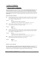
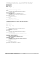
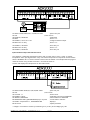
Turns on PWM output to Terminal V1
Turns on PWM output to Terminal V2
Disables PW M output on Terminal V1 ( V1 = high impedance )
Disables PW M output on Terminal V2 ( V2 = high impedance )
Note1: When PW M pins are disabled they are put into high impedance state.
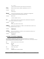
TAdddd
Sets the period of PW M output A on terminal V1 ( dddd=0000 to 1024 )
( 0000 = 0% 1024 = 100% )
example;
TA512<CR>
period is set to 512/1024 = 50%
TBdddd
Sets the period of PW M output B on terminal V2 ( dddd=0000 to 1024 )
( 0000 = 0% 1024 = 100% )
example;
TB232<CR>
period is set to 232/1024 = 22.65%
c) DIGITAL PORT COMMANDS
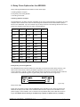
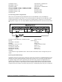
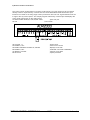
There is one, eight bit digital port on the ADR2000 labeled PORT A. The individual I/O lines are
labeled PA0-PA7. The following commands allow the user to;
-configure individual bits an input or output
-SET or RESET individual bits
-read individual bits
-read entire port in binary or decimal format
-write to entire port in binary or decimal format.
The digital port commands are;
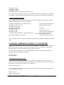
CPAxxxxxxxx
Configures each bit of PORT A . All eight bits must be specified. Order
is MSB-LSB ( x=1 for input, x=0 for output )
example;
CPA11110000<CR>
( PA7 ,PA6, PA5, PA4 are configured as inputs and PA3, PA2, PA1, PA0 are
configured as outputs )
SPAxxxxxxxx
Outputs binary data to PORT A. All eight bits must be specified.
Order is MSB-LSB. Individual bits configured as input are not
effected by this command. (x=1 or 0 )
example;
SPA10101000<CR>
( PA7, PA5, PA3 are set, PA6, PA4, PA2, PA1, PA0 are reset )
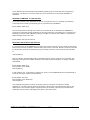
RPA
Returns status of all I/O lines in PORT A in binary format. Order is MSB-LSB.
Individual lines configured as output will return last data set on the port.
example;
RPA<CR>
ONTRAK CONTROL SYSTEMS INC.
9/24
www.ontrak.net