1
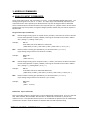
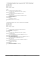
70 INPUT#1, SW1
80 PRINT#1, “RPA1"
90 INPUT#1,SW 2
100 T1$=”CLOSED” IF SW 1=1 THEN T1$=”OPEN
110 T2$=”CLOSED” IF SW 2=1 THEN T2$=”OPEN
120 PRINT “SW 1 is “ T1$
130 PRINT “SW 2 is “ T2$
140 GOTO 60
;saves status in variable SW1
;reads PA1 ( SW 2 )
;saves status in variable SW2
“ ;define T1$
“ ;define T2$
;print SW 1 status
;print SW 2 status
;repeat procedure
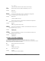
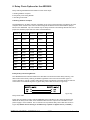
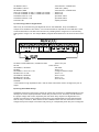
C) Connecting LED’s to Digital Ports
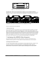
LED’s may be controlled using the digital I/O lines on the ADR2000. Only one additional
component is needed to drive LED’s. A current limit resistor is required for each LED with a value
of around 220 Ohms. The LED is the turned on by resetting PA0 to a logic zero or turned off by
setting PA0 to a logic one. The sample BASIC program demonstrates how to turn the LED on and
off.
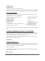
10 OPEN “COM1:9600,N,8,1,CS,DS,RS” AS#1
;opens com port
20 CLS
;clears screen
30 PRINT#1, “SETPA0"
;sets PA0*
40 REM
;forces <cr>
50 PRINT#1, “CPA11111110"
;configures PA0 as output
60 REM Turn on LED
;forces <cr>
70 PRINT#1, “RESPA0"
;turns on LED
80 REM Turn off LED
;forces <cr>
90 PRINT#1, “SETPA0"
;turns off LED
100 END
* PA0 remains in high impedance state until the CPA command is used to configure the port as
output.
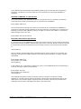
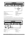
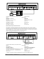
D) Driving Solid State Relays
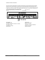
Solid-State relays that require a DC voltage to operate may be driven by ADR2000 digital I/O lines
directly if the current input specification for the relay is 20mA or less. The relay must be rated for
the proper voltage and current required by the load. Each relay requires one digital I/O line to
operate and requires no other external components. The sample BASIC program demonstrates
how the relay is turned on. Note that the I/O line is RESET before the CPA command is used to
configure the port as output to avoid the relay turning on unexpectedly when the port is configured.
ONTRAK CONTROL SYSTEMS INC.
19/24
www.ontrak.net