1
6. Daisy Chain Options for the ADR2000
Daisy chaining ADR2000 series boards involves three steps.
A. Setting Address Jumpers
B. Physically Connecting Boards
C. Sending commands
A. Setting Address Jumpers
The ADR2000 can be daisy-chained, regardless of the type of serial interface provided by the host
computer. Each board on the chain must be assigned an address via the BCD address jumper
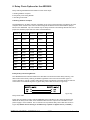
block on the ADR2000. Up to ten boards may be daisy-chained. The following table shows how to
jumper the address jumper block to select a board address.
Position 8
Position 4
Position 2
Position 1
Address
OPEN
OPEN
OPEN
OPEN
0
OPEN
OPEN
OPEN
JUMP
1
OPEN
OPEN
JUMP
OPEN
2
OPEN
OPEN
JUMP
JUMP
3
OPEN
JUMP
OPEN
OPEN
4
OPEN
JUMP
OPEN
JUMP
5
OPEN
JUMP
JUMP
OPEN
6
OPEN
JUMP
JUMP
JUMP
7
JUMP
OPEN
OPEN
OPEN
8
JUMP
OPEN
OPEN
JUMP
9
Table 1. Address Jumper Settings.
B. Physically Connecting Boards
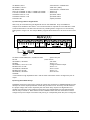
The ADR2000 series interface boards have two DB9 connectors that allow daisy chaining. The
data format used in daisy chaining is RS485 regardless of the host communication type. To
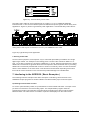
connect boards on a chain, a daisy chain cable must be constructed. The cable must provide two
connections for the RS485 signals. A typical daisy-chain cable is shown in Figure 5a)
Figure 5a):
Daisy-chain cable
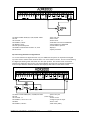
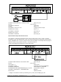
Power may be shared in daisy-chained ADR2000 series interfaces if two extra conductors are
added to the daisy-chain cable. Care should be taken that the output current limitation on the
power supply is not exceeded. The connections for a powered daisy-chain cable are shown in
Figure 5B) NOTE: Pow er sharing is available only if pow er is applied via J2 ( 7-15VDC ).
ONTRAK CONTROL SYSTEMS INC.
16/24
www.ontrak.net