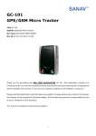
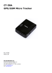
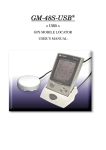
Download SANAV MU-201 GPS/GPRS Nano Tracker User Manual
Transcript
SANAV MU-201 GPS/GPRS Nano Tracker User Manual Revision: 1.1.6 Revision Date: 2012/08/01 August 2012 1.1.6 Copyright © 2011 San Jose Technology, Inc. All Rights Reserved. This document contains information that is the property of SANAV. This document may not be copied, reproduced, reduced to any electronic medium or machine readable form, or otherwise duplicated, and the information herein may not be used, disseminated or otherwise disclosed, except with the prior written consent of SANAV a MU-201 GPS/GPRS Nano Tracker User Manual MU-201 User Documentation Introduction SANAV MU-201 is a more compact version of focusing on the pets or asset tracking market. Its location can be real time tracked through internet or specified terminals. The user can communicate with the service server through GPRS/GSM network, transfer alarms of Emergency, Geo-fencing., Remote Control, and Lower power, and record the tracking history stored in internal memory through USB or website. This User Manual details the specification, hardware introduction, SMS commands and Tracker Status of MU-201. If you have any question about the operation of MU-201, please contact SANAV Customer Service [email protected]. Disclaimer This document, and all other related products, such as device, firmware, and software, is developed by San Jose Technology Inc. thoroughly. At the time of release, it is most compatible with specified firmware version. Due to the functionalities of the devices are being developed and improved from time to time, the change in the protocol, specification, and firmware functions are subjects to change without prior notice. SANAV is obligated to modify all the documentation without the limitation of time frame. A change notice shall be released to San Jose Technology Inc. customers upon the completion of document modification. San Jose Technology Inc. products are not intended to be used as life support or rescue equipments. San Jose Technology Inc. is not liable for any loss or injury caused by using or referencing to any products. Any possible means of using or integrating San Jose Technology Inc. products shall be avoided. Copyright Copyright © 2011, San Jose Technology, Inc. All rights reserved. The information in this publication is proprietary to San Jose Technology, Inc. No part of this publication may be used, disclosed, reproduced, adapted, translated, stored in a retrieval system, or transmitted in any form of or by any means, electronic or mechanical, for any purpose, without the prior written permission of San Jose Technology, Inc. although every precaution has been taken in the preparation of this publication, San Jose Technology, Inc., assumes no (i) responsibility for errors or omissions contained herein or (ii) liability for any damages resulting from the use of information contained herein. Information in this publication is subject to change without notice. b Copyright © 2011 San Jose Technology, Inc. All Rights Reserved. MU-201 GPS/GPRS Nano Tracker User Manual Document Amendments Revision Date F/W Version Comments 1.0.1 2011/1/5 B2.02T Main Functions implemented 1.0.2 2011/3/8 B2.02T LED & SMS commands Redefined 1.0.3 2011/4/20 B2.03T Bug fixes, VS status show/hide, HTTP get/post protocol. 1.0.4 2011/5/25 B2.05T Specifications& VS status show/hide 1.0.5 2011/7/29 V2.06 Vibration sensitivity 1.0.6 2011/8/18 V2.07 1. Define over speed logic 2. Add Tail Report On/Off 3. Modify all respond messages by SMS/COTA. 1.0.7 2011/10/5 V2.08 1. Define the battery gauge (%) data come after voltage information. 2. Px3kr connection support 1.0.8 2011/11/10 V2.09 Vibration Sensor logic 1.0.9 2011/12/7 V3.00 Quick reset 1.1.0 2011/12/27 V3.01 1. Heartbeat 2. During startup, GPS and GSM LED will stay ON (Red light) for 20 seconds. 1.1.1 2011/12/29 V3.02 Add GF clear data function 1.1.2 2012/3/21 V3.03 1. PIN Code 2. Show LP when under 3.7V LP, 3. MCU shutdown voltage is from 3.4V to 3.15V, 4. Power button 5. AUTO ON 6. Power OFF Message 7. Power ON/OFF schedule 8. Use”;” replace with”,” for GF and voltage message 1.1.3 2012/4/10 V3.031 Bug fix for PIN code setup fail 1.1.4 2012/7/2 V3.06 Log GPRMC sentences increased from 2000 to 5000 1.1.5 2012/7/16 V3.06 New amendment& release 1. Voltage Percentage (P53) 1.1.6 2012/8/1 V4.00 1. Log/Backup Mode features added. 2. HDOP value added in GPRMC sentences. c Copyright © 2011 San Jose Technology, Inc. All Rights Reserved. MU-201 GPS/GPRS Nano Tracker User Manual Contents Document Amendments .......................................................................... c MU-201 Hardware General Introduction ..................................................... 1 Specification .......................................................................................... 1 Package Contents .................................................................................................................. 2 Front View ................................................................................................................................ 3 MU-201 LED Indication ....................................................................................................... 3 Charging MU-201 .................................................................................................................. 5 Dimension ................................................................................................................................ 6 Command Setup for MU-201 .................................................................... 7 Change User Name ................................................................................. 8 Change Password ................................................................................... 9 Request IMEI Number ........................................................................... 10 Set up APN for GPRS Service .................................................................. 11 Set up Route for Data Transmission ......................................................... 12 Set up URL .......................................................................................... 14 Set up TCP/UDP Server Address ............................................................. 15 Set up Phone Book List.......................................................................... 16 Set up Security Phone Book List ............................................................. 17 Enable Security Phone Book ................................................................... 18 Set up Answer Call Mode ....................................................................... 19 Set up SOS Phone Book ........................................................................ 20 Set up SOS Event Report Interval ........................................................... 21 SOS Event Report Flow .......................................................................... 22 Stop SOS Report (Exit from SOS Mode) ................................................... 23 Set up Auto Report ............................................................................... 24 Auto Report by Distance ........................................................................ 25 Auto Report by Stationary Times ............................................................ 26 Current Position Polling.......................................................................... 28 Set up Polling Format ............................................................................ 29 Google MAP Report with Address ............................................................ 30 Set up Address Language ...................................................................... 32 Language Codes Reference Table ............................................................ 33 Set up Park/Move ................................................................................. 35 Set up Move Interval............................................................................. 36 Set up Vibration ................................................................................... 37 Show Vibration Status ........................................................................... 38 Vibration Sensitivity .............................................................................. 39 Set up Over Speed ............................................................................... 40 Set up Over Speed Interval .................................................................... 41 Set up Geo-Fence Coordinates................................................................ 42 Enable Geo-Fence ................................................................................. 44 Set up Geo-Fence Event Report Interval .................................................. 46 d Copyright © 2011 San Jose Technology, Inc. All Rights Reserved. MU-201 GPS/GPRS Nano Tracker User Manual Setup Backup/Log Interval Mode (Pre-defined Backup Times) ..................... 47 Erase the Logged Data .......................................................................... 49 Power Button ....................................................................................... 50 Power Cord AUTO ON ............................................................................ 51 Power ON/OFF Schedule ........................................................................ 53 Request Battery Voltage ........................................................................ 54 Voltage Percentage ............................................................................... 55 Reset to Default Setting ........................................................................ 56 Tail Report ........................................................................................... 57 Appendix 1: Tracker Event List ............................................................... 59 Appendix 2: GPRMC Data Output Format ................................................. 60 Appendix 3: NMEA 0183 GPRMC Data Format ........................................... 63 FAQ .................................................................................................... 64 Warranty Regulation ............................................................................. 65 e Copyright © 2011 San Jose Technology, Inc. All Rights Reserved. MU-201 GPS/GPRS Nano Tracker User Manual MU-201 Hardware General Introduction Specification GSM Quad-Band: 850/900/1800/1900MHz Frequency: Compliant to GSM phase 2/2+ -Class 4 (2W @ 850/900MHz) -Class 1 (1W @ 1800/1900MHz) GPRS: RMS Phase Error: GPRS multi-slot class 10 GPRS mobile station class B ≤5deg Max Out RF power: 33.0dBm±2dBm Dynamic Input Range: -15 ~ -102 dBm Receiving Sensitivity: Class II RBER≤2%(-102dBm) Stability Of Frequency: Greater than 2.5ppm Max Frequency Error: ±0.1ppm GPS GPS Chipset: UBX-G5010 50 Channels Receiver Type GPS L1 frequency, C/A Code GALILEO Open Service L1 frequency Tracking & Navigation -160 dBm Sensitivity: Acquisition -160 dBm Cold Start (Autonomous) -145 dBm TTFF (Open Sky): Cold start 40 s average Warm start <30s Hot start <2 s User Interface Mini USB Connector: Include charger Power Button: Power on and power off. General Dimension: 60mm* 35 mm * 19mm Weight: 65 g Backup Battery: Li-Polymer 650 mAh , 3.7V Standby Time: Charge Voltage 10 minutes reporting: 50 Hours (estimation) 60 minutes reporting: 100 Hours (estimation) 5 V DC Air Interface Protocol Transmit Protocol: TCP,UDP,SMS Geo-Fence: 10 Geo-Fence regions can be defined. Low Power Alarm: Alarm when battery is low Power On Report: Report on power up Operating Environment Operating Temperature 0°C to +55°C Storage Temperature -20°C to +85°C *This specification is subject to change without prior notice 1 Copyright © 2011 San Jose Technology, Inc. All Rights Reserved. MU-201 GPS/GPRS Nano Tracker User Manual Package Contents MU-201 x 1 Power Cord (USB Type) x 1 AC Adapter x 1 100~240V AC / 1.2A Utility CD x 1 ( Manual& SW) Note: Connect Power Cord to AC Adapter to be a whole power charging solution. Optional Accessories Utility AP Data Cable 2 Note the Difference!!! Copyright © 2011 San Jose Technology, Inc. All Rights Reserved. MU-201 GPS/GPRS Nano Tracker User Manual Front View z GSM LED (Red) SOS/Park Button z GPS LED (Blue) z SOS - Press and hold for 3s to trigger SOS Mode. z Exit from SOS - In SOS Mode, press and hold for 3s again. z Park - One Short Press to trigger Park Mode. z Exit from Park – In Park mode, one short press again to exit Park Mode. MU-201 LED Indication Device Status GSM Red GPS Green Red Steady ON Steady ON Power ON then following then following Long Press Power key for 3s booting procedure booting procedure (About 20s) (About 20s) Blue Power OFF Steady ON around 8s Steady ON around 8s Long Press Power key for 3s Than power off Than power off GPS is not fixed - - Flash/5s - - - - Flash/5s GPS sleeping mode - - - - GSM NOT in Service Flash/5s - - - - Flash/5s - - Steady ON - Steady ON - Park Trigger on - - Flash 5 times Park state - Flash/5s - - - - Flash 5 times - Flash 5 times - - Flash/1s - Battery Charging - - - Flash/1s Battery Full Charged - Flash/1s - - OFF OFF - - GPS Status GPS is fixed GSM Status GSM in Service SOS Mode Park Mode In SOS Mode Park Trigger off Receive SMS Command Low Power NO SIM or Invalid SIM ERROR (After Power On) 3 - Copyright © 2011 San Jose Technology, Inc. All Rights Reserved. MU-201 GPS/GPRS Nano Tracker User Manual Top View Power button Turn ON/OFF: Press and hold for more than 3 seconds. ON: Both red LEDs steady ON OFF: Both green& blue LEDs steady ON Note: Please insert SIM card BEFORE turning ON the device. Bottom View Hidden Microphone (For Overhearing) Side View SIM Card Holder 4 Copyright © 2011 San Jose Technology, Inc. All Rights Reserved. MU-201 GPS/GPRS Nano Tracker User Manual Insert SIM Card (Please note the SIM Card direction) Note: Please make sure PIN Code function is disabled before inserting the SIM card. Charging MU-201 MINI USB 8 PIN Plug power cord into Mini USB socket for charging. (5V DC Input) Charge the device for 2~3 hours for 1st time charging. 5 Copyright © 2011 San Jose Technology, Inc. All Rights Reserved. MU-201 GPS/GPRS Nano Tracker User Manual Dimension 60 mm 35 mm 19mm Weight: 65g 6 Copyright © 2011 San Jose Technology, Inc. All Rights Reserved. MU-201 GPS/GPRS Nano Tracker User Manual Command Setup for MU-201 MU-201 currently provides SMS command and COTA (TCP) command for remote setup. User can setup the MU-201 by following the instructions shown in following chapters via SMS/COTA. Key the specific SMS message in your cellular phone and send it to the SIM number of MU-201. The setup messages are showed in the following sections. 1: The default setting: Default ID is “username”. Please read chapter Change User Name to desired ID. Default password is “0000”. Please read chapter Change Password to change the password. There is no number in the default contact. Please read chapter Set up Phone Book List to add the number. Default setting of Auto Report is deactivated. Please read chapter Set up Auto Report by Time to setup the regular auto report. Default setting of APN is only suitable for Taiwan GSM network. Please read chapter Set up APN for GPRS Service to change the APN. Default setting of URL is http://www.sanavtw.com/uploadM1.php. Please read chapter Set up URL to change the URL for http server setup. Before doing any setup, please ensure the device is connected with the GSM network. The GSM LED must light on. And please note the device is not in SOS/Panic mode. 2: Please note that all the characters which include #, * and comma (,) should be HALFWIDTH form. 3: Please be aware of the upper (capital)/lower cases when entering the SMS command. 4: While entering any SMS command, note that NO SPACE is allowed between the characters, comma and signs in the SMS. 5: Any setup command must be started with a “#” sign and ended up with a “*” sign. 6: The comma (,) can be abbreviated if no further setup required for the command besides Set up APN for GPRS Service. Please refer to the examples of Set up Auto Report. 6: Add or not add the “+ “sign in front of the cellular phone number(s) are both acceptable, while the”+” sign should precede the international call prefixes. The specified international call prefix is required if “+ “sign is not added. 7: The device will update setting Only when the password, username and setup command are all correct. If the command is not valid, a failure report is going to be sent to the user’s cell phone. 8: Some PREPAID PHONE CARD SIM modules do not enable or even support GPRS service. Please consult with GSM carrier for further information. 7 Copyright © 2011 San Jose Technology, Inc. All Rights Reserved. MU-201 GPS/GPRS Nano Tracker User Manual Change User Name Generally, SMS command execution needs correct user name with password, or it will remain the same setting. The SMS command default user name is “username”. It can be changed by following the command format. For example, entering the SMS command as the following allows user to change the user name from “username” to a new user name “jacky”. Only enter new command with new user name after it has been changed. Setup Format: #「username」,「Password」,「Function Mode」,「New User Name」* Command: #username,0000,1,jacky* SMS/ COTA Command Description # Start sign. user name Default ID of the device. 0000 Default password. If you have changed the password, please use the updated one. 1 Mode 1 defines user name setup mode. jacky New user name changed by the user. At the maximum of 16 characters, including a~z,A~Z,0~9, @ - _ / .!%& Please notice that you should notice if the letters is capitalized or in small letters when sending the command. * End sign. Table: User Name Change Format Description Situation Message Reply Setup Succeeds <OK>Username setup,V4.231;100% Setup Fail <FAIL>Username setup,V4.231;100% Emergency Mode <FAIL>PANIC ON; Command not Allow!,V4.200;100% Table: User Name Change Response Description 8 Copyright © 2011 San Jose Technology, Inc. All Rights Reserved. MU-201 GPS/GPRS Nano Tracker User Manual Change Password Generally, SMS command execution needs correct user name with password, or it will remain the same setting. The SMS command default password is “0000”. It can be changed by following the command format. For example, entering the SMS command as the following allows user to change the password from “0000” to a new password “1111”. Only enter new command with new password after it has been changed. Setup Format: #「username」,「Password」,「Function Mode」,「new Password」,「new Password」* Command: #username,0000,2,1111,1111* SMS/ COTA Command Description # Start sign. username Default ID of the device. If you have changed the username, please use the updated one. Default password. If you have changed the password, please use the updated one. 0000 2 Mode 2 defines the password setup mode. 1111 New password (Please note at the maximum of 4 number) 1111 Reconfirm the password * End sign. Table: Password Change Format Description Situation Message Reply Setup Succeeds <OK>Password setup,V4.239;100% Setup Fail <FAIL>Password setup,V4.239;100% Emergency Mode <FAIL>PANIC ON; Command not Allow!,V4.200;100% Table: Password Change Response Description 9 Copyright © 2011 San Jose Technology, Inc. All Rights Reserved. MU-201 GPS/GPRS Nano Tracker User Manual Request IMEI Number IMEI stands for International Mobile Equipment Identification, a unique number for identifying mobile devices validity in GSM network. As above stated, each device has a unique IMEI number. Entering the command as the following allows user to check the IMEI number of the device for network registration and tracking. Setup Format: #「username」,「Password」,「Function Mode」* Command: #username,0000,imei* SMS/ COTA Command Description # Start sign. username Default ID of the device. If you have changed the user name, please use the updated one. 0000 Default password. If you have changed the password, please use the updated one. imei Mode “imei” defines the device IMEI number request mode. * End sign. Table: IMEI Number Request Format Description Situation Message Reply Setup Succeeds <OK>Read IMEI=357566000046804,V4.097;98% Table: IMEI Number Request Response Description 10 Copyright © 2011 San Jose Technology, Inc. All Rights Reserved. MU-201 GPS/GPRS Nano Tracker User Manual Set up APN for GPRS Service Access Point Name (APN) is a protocol that typically allows a user's device to access the internet using the mobile phone network. It is a network identifier used by a mobile device when connecting to a GSM carrier. The carrier will then examine this identifier to determine what type of network connection should be created. For uploading the data to a web server, a set of GPRS APN from your GSM network is required. Various GSM network provides different GPRS APN settings. Please ask your GMS carrier about the APN settings. If the user name and password of APN are indefinite or showed in blank, just leave the parameters empty (no space). User can follow the Setup Format below to setup the APN that is provided by your GSM carrier. Setup Format: #「username」,「Password」,「Function Mode」,「APN name」,「APN username」,「APN password」,「APN DNS」* Example1:#username,0000,3,twm,1234,1234, 172.20.2.10* Example2:#username,0000,3,internet,,* Note1: The total length of APN name, APN username, APN Password, and APN DNS should be less than 70 characteristics. Note2: Some PREPAID PHONE CARD SIM modules do not enable or even support GPRS service. Please consult with GSM carrier for further information. SMS/ COTA Command Description # Start sign. username Default ID of the device. If you have changed the user name, please use the updated one. Default password. If you have changed the password, please use the updated one. 0000 3 Mode 3 defines the APN setup mode. twm APN Name 1234 APN user name (optional) 1234 APN Password (optional) 172.20.2.10 APN DNS (optional) * End sign. Table: APN Setup Format Description Situation Message Reply Setup Succeeds <OK>GPRS APN setup,V4.195;100% Emergency Mode <FAIL>PANIC ON; Command not Allow!,V4.091;98% Table: APN Setup Response Description 11 Copyright © 2011 San Jose Technology, Inc. All Rights Reserved. MU-201 GPS/GPRS Nano Tracker User Manual Set up Route for Data Transmission This SMS command instructs the device decide to transmit GPS (GPRMC) positioning data to where in which protocol. Please confirm the back-end server protocol type and corresponded URL or IP address (with port number if required) before setup. There are 4 main protocols available for transmitting route setup: 1. HTTP: Hypertext Transfer Protocol. An internet browser based server protocol that usually has a specified URL (Uniform Resource Locator). 2. TCP/IP: Transmission Control Protocol. An OSI Transport layer protocol that has more complex frame structure, higher reliability but slower processing speed than UDP/IP. 3. UDP/IP: User Datagram Protocol. An OSI Transport layer protocol that has faster processing than TCP/IP but does not guarantee data delivery. 4. SMS: The DEVICE will send GPS data by SMS message format to Cellular phone. User can choose the route to transmit the data by HTTP/TCP/UDP protocol individually or with SMS message as a backup route. Please refer to the following table for the route setup. Setup Format: #「username」,「Password」,「Function Mode」,「0,2,4,6,7,8 or 9」* Command: #username,0000,14,6* SMS/ COTA Command Description # Start sign. Username Default ID of the device. If you have changed the user name, please use the updated one. 0000 Default password. If you have changed the password, please use the updated one. 14 Mode 14 defines Transmission Route mode. 0 6 message instead. 2 HTTP only. Send data to HTTP server. No SMS backup route. 4 SMS only. Send data by SMS message to cell phone. No backup route. 6 7 8 9 * HTTP/SMS. Send data to HTTP server. If the route is not available, send data by SMS TCP/SMS. Send data to TCP server. If the route is not available, send data by SMS message instead. TCP Only. Send data to TCP server. No SMS backup route. UDP/SMS. Send data to UDP server. If the route is not available, send data by SMS message instead. UDP Only. Send data to UDP server. No SMS backup route. End sign. Table: Transmission Route Setup Format Description 12 Copyright © 2011 San Jose Technology, Inc. All Rights Reserved. MU-201 GPS/GPRS Nano Tracker User Manual Situation Message Reply <OK>Route is HTTP/SMS mode, V3.793;56% <OK>Route is HTTP mode, V3.793;56% <OK>Route is SMS mode, V3.793;56% Setup Succeeds <OK>Route is TCP/SMS mode, V3.793;56% <OK>Route is TCP mode, V3.793;56% <OK>Route is UDP/SMS mode, V3.793;56% <OK>Route is UDP mode, V3.793;56% <FAIL>PANIC ON; Command not Allow!,V4.091;98% <FAIL>PANIC ON; Command not Allow!,V4.091;98% <FAIL>PANIC ON; Command not Allow!,V4.091;98% Emergency Mode <FAIL>PANIC ON; Command not Allow!,V4.091;98% <FAIL>PANIC ON; Command not Allow!,V4.091;98% <FAIL>PANIC ON; Command not Allow!,V4.091;98% <FAIL>PANIC ON; Command not Allow!,V4.091;98% Table: Transmission Route Setup Response Description 13 Copyright © 2011 San Jose Technology, Inc. All Rights Reserved. MU-201 GPS/GPRS Nano Tracker User Manual Set up URL This SMS command instructs the device to transmit GPS (GPRMC) positioning data to a specified URL (Uniform Resource Locator) or IP address of HTTP protocol server for real time GPS tracking. Entering the SMS command as the following allows user to changes the address to “http://www.sanavtw.com/uploadM1.php”. The address will be assigned to receive the GPS data sent by the device. Setup Format: #「username」,「Password」,「Function Mode」,「URL」* Command: #username,0000,4, http://www.sanavtw.com/uploadM1.php* Note: The URL should be less than 80 characteristics. SMS/ COTA Command Description # Start sign. username Default ID of the device. If you have changed the user name, please use the updated one. Default password. If you have changed the password, please use the updated one. 0000 4 Mode 4 defines the URL setup mode. http://www.sanavtw.com/ URL of the HTTP server. uploadM1.php * End sign. Table: URL or IP Setup Format Description Situation Message Reply Setup Succeeds <OK>IP/Domain setup, V3.793;56% Emergency Mode <FAIL>PANIC ON; Command not Allow!,V4.091;98% Table: URL or IP Setup Response Description 14 Copyright © 2011 San Jose Technology, Inc. All Rights Reserved. MU-201 GPS/GPRS Nano Tracker User Manual Set up TCP/UDP Server Address User can use IP address setup command to indicate the device transmit GPS (GPRMC) positioning data to a specified TCP or UDP protocol based server for real time tracking. Entering the SMS command as the following allows user to change the address to specified IP and port. The IP address will be assigned to receive the GPS data sent by the device. Setup Format: #「username」,「Password」,「Function Mode」, 「TCP/UDP server address」* Command: #username,0000,18,220.128.123.1:7878 * Or #username,0000,18,icare-u.com.tw:12345* SMS/ COTA Command Description # Start sign. username Default ID of the device. If you have changed the user name, please use the updated one. 0000 Default password. If you have changed the password, please use the updated one. 18 Mode 18 defines the TCP/UDP Server Address setup mode. 220.128.123.1:7878 TCP/UDP Server Address and Port * End sign. / Domain name Table: Server Address Setup Format Description Situation Message Reply Setup Succeeds <OK>TCP/UDP URL setup, V3.793;56% Emergency Mode <FAIL>PANIC ON; Command not Allow!,V4.091;98% Table: Server Address Setup Response Description 15 Copyright © 2011 San Jose Technology, Inc. All Rights Reserved. MU-201 GPS/GPRS Nano Tracker User Manual Set up Phone Book List There are three main purposes of Phone Book List setup: 1. Backup Route: As a backup route when the data is not able to send to the server. The data will be sent to 1st cellular number PH-01 only. 2. SOS Alarm Route: When the device is in SOS mode, it will send SOS event report to the phone numbers in the list. 3. SMS Data Route: When the data route is set to SMS, the device will send GPRMC data to to 1st cellular number PH-01 only. Use this SMS command to set up the cellular phone book (Max. of 3 numbers) as the following format: Setup Format: #「username」,「Password」,「Function Mode」,「PH-01」,「PH-02」,「PH-03」* Command: #username,0000,5,+886123456789,+492234567890,+866323456789* Note1: Add or not add the “+ “sign in front of the cellular phone numbers are both acceptable, while the”+” sign should precede the international call prefixes. Note2: When the Phone Book is set and Security Phone Book is enabled, the numbers will be considered as security numbers. Only the security numbers are allowed to do the command setting and overhearing (answer call) from the device. SMS/ COTA Command Description # Start sign. username Default ID of the device. If you have changed the user name, please use the updated one. Default password. If you have changed the password, please use the updated one. 0000 5 Mode 5 defines the Phone Book List setup mode. +886123456789 1st cellular numbers, PH-01 +492234567890 2nd cellular numbers, PH-02 +866323456789 3rd cellular numbers, PH-03 * End sign. Table: Phone Book List Setup Format Description Situation Message Reply Setup Succeeds <OK>;P1=0935304180;P2=;P3=, V3.793;56% Emergency Mode <FAIL>PANIC ON; Command not Allow!,V4.091;98% Table: Phone Number List Setup Response Description 16 Copyright © 2011 San Jose Technology, Inc. All Rights Reserved. MU-201 GPS/GPRS Nano Tracker User Manual Set up Security Phone Book List Security Phone Number list allows limited administrators to manage and change the settings of the device. When the Security Phone Numbers are set, even the User Name and Password are correct, if the setup number is not matched with the list, the setup or any change will be invalid. By the way, only the administrators of the list are allowed to call the device for real time communication when the Security Phone Numbers are set. Maximum 10 sets of numbers are available. Setup Format: #「username」,「Password」,「Function Mode」, 「1~10」, 「Phone number」* Command: #username,0000,secphone,1,+886123456789* SMS/ COTA Command Description # Start sign. username Default ID of the device. If you have changed the user name, please use the updated one. 0000 Default password. If you have changed the password, please use the updated one. Secphone Mode “secphone” defines the Security Phone Book setup mode. 1 The ID of each phone number. User can put 1~10 here +886123456789 The Security Phone number you would like to assign to the ID. * End sign. Table: Security Phone Number Setup Format Description Situation Message Reply Setup Succeeds <OK>Sec phone(1)=0916004972,V4.112;100% Emergency Mode <FAIL>PANIC ON; Command not Allow!,V4.091;98% Table: Security Phone Number Setup Response Description 17 Copyright © 2011 San Jose Technology, Inc. All Rights Reserved. MU-201 GPS/GPRS Nano Tracker User Manual Enable Security Phone Book User can use this command to enable/disable Security Numbers Functions. Setup Format: #「username」,「Password」,「Function Mode」,「on/off」* Command: #username,0000,security,on* Note: The numbers preset in “SOS Phone” and “Phone Book” are also considered as Security Phone number once this function is enabled. SMS/ COTA Command Description # Start sign. username Default ID of the device. If you have changed the user name, please use the updated one. 0000 Default password. If you have changed the password, please use the updated one. security Mode “security” defines the enable Security Phone Number mode. on/off on Only accept calls/commands by security number. off Accept all the calls/commands. * End sign. Table: Enable Security Phone Number Format Description Situation Setup Succeeds Emergency Mode Message Reply <OK>Security ON!,V4.112;100% <OK>Security OFF!,V4.112;100% <FAIL>PANIC ON; Command not Allow!,V4.091;98% Table: Enable Security Phone Number Response Description 18 Copyright © 2011 San Jose Technology, Inc. All Rights Reserved. MU-201 GPS/GPRS Nano Tracker User Manual Set up Answer Call Mode User can use Answer Call (Voice Mode) command to define the response when MU-201 is receiving an incoming call. The device can answer the call automatically or hang up the call and send current location message. Setup Format: #「username」,「Password」,「Function Mode」, 「0~3」* Command: #username,0000,8,1* Note: If user has enabled “Security Phone Book” function, MU-201 will verify whether the caller’s number is in the Security Phone Book. If not, MU-201 will not react to the incoming call. SMS/ COTA Command Description # Start sign. username Default ID of the device. If you have changed the user name, please use the updated one. 0000 Default password. If you have changed the password, please use the updated one. 8 Mode 8 defines the Voice Mode setup. 1 0 /1 The device will answer the incoming call automatically. * 2 The device will hang up the call and respond its current location to caller’s cell phone. 3 The device will hang up the call and respond its current location to the defined route. End sign. Table: Answer Call Mode Setup Format Description Situation Message Reply <OK>Monitor mode 0/1;auto answer call, V3.793;56% Setup Succeeds <OK>Monitor mode 2;reply to caller V3.793;56% <OK>Monitor mode 3;reply by router,V4.156;100% Emergency Mode <FAIL>PANIC ON; Command not Allow!,V4.091;98% Table: Answer Call Mode Setup Response Description 19 Copyright © 2011 San Jose Technology, Inc. All Rights Reserved. MU-201 GPS/GPRS Nano Tracker User Manual Set up SOS Phone Book Use this SMS/COTA command to define the SOS cellular number by following the format below. The device will first send 1 SOS event/alarm report to all number in the phone book and then make a phone call to the SOS phone number immediately. Setup Format: #「username」,「Password」,「Function Mode」,「SOS Phone」* Command: #username,0000,sosphone,+886123456789* Note: Add or not add the “+ “sign in front of the cellular phone number(s) are both acceptable, while the”+” sign should precede the international call prefixes. SMS/ COTA Command Description # Start sign. username Default ID of the device. If you have changed the user name, please use the updated one. Default password. If you have changed the password, please use the updated one. 0000 sosphone Mode “sosphone” defines the SOS Phone Book setup mode. +886123456789 SOS Phone number * End sign. Table: SOS Phone Book Setup Format Description Situation Message Reply Setup Succeeds <OK>SOS phone=0935304180, V3.793;56% Emergency Mode <FAIL>PANIC ON; Command not Allow!,V4.091;98% Table: SOS Phone Book Setup Response Description 20 Copyright © 2011 San Jose Technology, Inc. All Rights Reserved. MU-201 GPS/GPRS Nano Tracker User Manual Set up SOS Event Report Interval Use this SMS/COTA command to predefine the SOS report interval by following the format below. Setup Format: #「username」,「Password」,「Function Mode」,「SOS report interval」,「Total number of SOS reports」 * Command: #username,0000,15,30,3* Note: SOS report interval ranges from 1~65000 seconds; SOS report times ranges from 1~9999 times. SMS/ COTA Command Description # Start sign. username Default ID of the device. If you have changed the user name, please use the updated one. Default password. If you have changed the password, please use the updated one. 0000 15 Mode 15 defines the SOS Report Interval setup mode. 30 It defines the report interval (in this case, one report per 30s) when SOS is triggered. 3 It defines how many times the SOS report will be sent to the assigned route. (in this case, 3 times) * End sign. Table: SOS Alarm Report Interval Setup Format Description Situation Message Reply Setup Succeeds <OK>Panic setup, V3.793;56% Emergency Mode <FAIL>PANIC ON; Command not Allow!,V4.091;98% Table: SOS Alarm Report Interval Setup Response Description 21 Copyright © 2011 San Jose Technology, Inc. All Rights Reserved. MU-201 GPS/GPRS Nano Tracker User Manual SOS Event Report Flow Long Press SOS Button Yes Check Phonebook No Send SOS event report to all numbers Yes Check SOS Phone Send SOS message to all numbers Call hangs up No Send the rest SOS event reports to server by interval and times SOS Event Report Flow Description 1. SOS mode: Long press power button to more than 3s, the SOS function will be triggered with "beep" sound. 2. Send 1 SOS event/alarm report to all number in the phone book if the phone book number is set. Please refer to Set up Phone Book List. 3. Calls SOS phone number if this number is set in the SOS phone book. Please refer to Set up SOS Phone Book. 3.1 User can finish the call anytime without limitation. 3.2 Send the rest SOS event reports to the server by report interval and times after the call is finished. 4. 22 For SOS event report interval and times setup, please refer to Set up SOS Event Report Interval. Copyright © 2011 San Jose Technology, Inc. All Rights Reserved. MU-201 GPS/GPRS Nano Tracker User Manual Stop SOS Report (Exit from SOS Mode) While the device is in SOS Mode, user can use this SMS/COTA command to stop the SOS report and Exit from SOS mode. Setup Format: #「username」,「Password」,「offpanic」* Command: #username,0000,offpanic* Note: User can exit SOS Mode by long pressing the SOS button again. Please refer to Hardware General Introduction. SMS/ COTA Command Description # Start sign. username Default ID of the device. If you have changed the user name, please use the updated one. Default password. If you have changed the password, please use the updated one. 0000 offpanic Mode offpanic defines the SOS Exit mode. * End sign. Table: Exit from SOS Mode Setup Description Situation Message Reply Setup Succeeds <OK>Panic OFF to normal mode, V3.793;56% Table: Exit from SOS Mode Response Description 23 Copyright © 2011 San Jose Technology, Inc. All Rights Reserved. MU-201 GPS/GPRS Nano Tracker User Manual Set up Auto Report Generally, the device will generate GPS (GPRMC) data and report to server, specified cellular phone or network routes. Auto Report setup can enable the device report GPS data automatically during a period of time. Use this command to set up the frequency of Auto Report. The device can report according to time interval. If you send the SMS command as the following example, the device will send a report every 5 minutes (300 seconds) and the total number of reports is 99. Setup Format: #「User Name」,「Password」,「Function Mode」,「Intervals (sec.)」,「Total number of reports」,,, [Time Unit(s/m/h)]* Example1:#username,0000,6,300,99* Example2:#username,0000,6,300,99,,,s* Note: The report times of Auto Reports can be set by entering the digits from 1 to 9998 in the「total number of reports」 field. When 9999 is entered, the device will generate unlimited Auto Reports, when 0 is entered, the device will stop/disable Auto Report. SMS/ COTA Command Description # Start sign. username Default user name of the device. If you have changed the username, please use the updated one. Default password. If you have changed the password, please use the updated one. 0000 6 Mode 6 defines Auto Report setup mode. 300 Time Interval (period) of Auto Report. 99 Times (frequency) of Auto Reports that will be sent automatically. s Time Unit as “s” for seconds (default), “m” for minutes, and “h” for hours. In this example, we put “300” in constant interval of sending data and blank for the Time Unit, so the actual report will be 300 seconds. * End sign. Table: Auto Report Setup Format Description Situation Message Reply Setup Succeeds <OK>Auto setup,V3.793;56% Emergency Mode <FAIL>PANIC ON; Command not Allow!,V4.091;98% Table: Auto Report Setup Response Description 24 Copyright © 2011 San Jose Technology, Inc. All Rights Reserved. MU-201 GPS/GPRS Nano Tracker User Manual Auto Report by Distance The GPS (GPRMC) data can report to server or cellular phone automatically during a period of time or during a distance of travel. Use this command to set up the distance Auto Report. The device will report only when both time interval and distance traveled are matched. If you send the SMS command as the following example, the device will check the distance traveled every 5 minutes (300 seconds) with previous GPS data, the device will send Auto Report if the distance exceeds 100m from last known position, or it will not send report if the distance does not exceed 100m, it will check the distance again at the next 5 minute time interval. The total number of reports times is 99. Setup Format: #「User Name」,「Password」,「Function Mode」,「Intervals (sec.)」,「Total number of reports」, 「Distance Interval(m)」,,[Time Unit(s/m/h)]* Command: #username,0000,6,300,99,100* NOTE: When the “Distance” interval or “Stationary Detection” is set, the tracker status (event) will be “AGF” instead of “AUTO”. SMS/ COTA Command Description # Start sign. username Default user name of the device. If you have changed the username, please use the updated one. Default password. If you have changed the password, please use the updated one. 0000 6 Mode 6 defines Auto Report setup mode. 300 Time Interval (period) of Auto Report. 99 Times (frequency) of Auto Reports that will be sent automatically. Distance Interval: when the auto report function is activated, the tracker will take the current position as the start. If this value is defined, when the tracker exceeds the distance 100 traveled during a time of period, the event report will be sent to the assigned route. The unit of this function is meter. The minimum distance setting is 100m. s Time Unit as “s” for seconds (default), “m” for minutes, and “h” for hours. * End sign. Table: Auto Report by Distance Setup Format Description Situation Message Reply Setup Succeeds <OK>AGF setup, V3.793;56% Emergency Mode <FAIL>PANIC ON; Command not Allow!,V4.091;98% Table: Auto Report by Distance Setup Response Description 25 Copyright © 2011 San Jose Technology, Inc. All Rights Reserved. MU-201 GPS/GPRS Nano Tracker User Manual Auto Report by Stationary Times The GPS (GPRMC) data can report to server or cellular phone automatically during a period of time or during a distance of travel or by stationary (vehicle stop/park status) times. Use this command to set up the stationary detection times of Auto Report, the device will report 2 types of Auto Reports: Distance Auto Reports and Stationary Auto Reports. If you send the SMS command as the following example, the device will check the distance traveled every 5 minutes when vehicle is moving, and check the stationary status every 5 minutes (300 seconds) when vehicle is stopped. The device will send Auto Report if the device detected continuously 10 times stationary status, so the actual Auto Report interval will be 5 minutes x 10 =50 minutes (it means the device will send stationary Auto Report every 50 minutes). The device will not send report if the device detected stationary status fewer than 10 times or non-continuity 10 times stationary status. The total number of reports times is 99. Setup Format: #「User Name」,「Password」,「Function Mode」,「Intervals (sec)」,「Total number of reports」,「Distance Interval(m)」,「stationary Detection(times)」, [Time Unit(s/m/h)]* Command: #username,0000,6,300,99,100,10,s* NOTE: When the “Distance” interval or “Stationary Detection” is set, the tracker status (event) will be “AGF” instead of “AUTO”. SMS/ COTA Command Description # Start sign. username Default user name of the device. If you have changed the username, please use the updated one. Default password. If you have changed the password, please use the updated one. 0000 6 Mode 6 defines Auto Report setup mode. 300 Time Interval (period) of Auto Report. 99 Times (frequency) of Auto Reports that will be sent automatically. Distance Interval: when the auto report function is activated, the tracker will take the current position as the start. If this value is defined, when the tracker exceeds the distance 100 traveled during a time of period, the event report will be sent to the assigned route. The unit of this function is meter. The minimum distance setting is 100m. Stationary Detection: If this value is defined by 5, the tracker will detect if the tracker 10 exceeds the circle for 5 times. If the tracker doesn’t exceed this circle, the tracker will send a notice command. The unit is times. s Time Unit as “s” for seconds (default), “m” for minutes, and “h” for hours. In this example, we put “300” in constant interval and “s” for the Time Unit, so the actual report will be 300 seconds. * End sign. Table: Auto Report by Stationary Setup Format Description 26 Copyright © 2011 San Jose Technology, Inc. All Rights Reserved. MU-201 GPS/GPRS Nano Tracker User Manual Situation Message Reply Setup Succeeds <OK>AGF setup, V3.793;56% Emergency Mode <FAIL>PANIC ON; Command not Allow!,V4.091;98% Table: Auto Report by Stationary Setup Response Description 27 Copyright © 2011 San Jose Technology, Inc. All Rights Reserved. MU-201 GPS/GPRS Nano Tracker User Manual Current Position Polling The user can send the SMS command according to the example shown below to have the device send GPS data right away (SMS Polling). It will transmit current GPS data to the USER’S CELL PHONE NUMBER at once. While the route is set to SMS mode, it will transmit current data to your cell phone that you sent the SMS Polling command to the device. Setup Format: #「username」,「Password」,「Function Mode」* Command: #username,0000,10* Note: For Google hyper-link setting, please refer to Set up SMS Google Map Report. SMS/ COTA Command Description # Start sign. user name Default ID of the device. If you have changed the user name, please use the updated one. Default password. If you have changed the password, please use the updated one. 0000 10 Mode 10 defines the SMS Polling setup mode. * End sign. Table: SMS Polling Setup Format Description Situation Setup Succeeds Message Reply username,$GPRMC,062032.00,A,2457.80696,N,12125.52737,E,0.344,26.82,090211,,,A* 59,POLL, V3.793;56% Setup Succeeds username,http://maps.google.com/maps?q=24.963528,121.425658(tracker)&,POLL, Google hyper-link V3.793;56% Table: SMS Polling Setup Response Description 28 Copyright © 2011 San Jose Technology, Inc. All Rights Reserved. MU-201 GPS/GPRS Nano Tracker User Manual Set up Polling Format The user can send the SMS/COTA polling according to the shown example to get desired information. It defines the report format when you set SMS polling. Setup Format: #「username」,「Password」,「Function Mode」, 「Report Format Code」* Command: #username,0000,10,2* SMS/ COTA Command Description # Start sign. user name Default ID of the device. If you have changed the user name, please use the updated one. Default password. If you have changed the password, please use the updated one. 0000 10 Mode 10 defines the SMS Polling setup mode. 2 Report Format Code: * 2 Google Map Hyperlink 4 Actual Address (show the nearest address from Google database) 6 To include both Google Map Hyperlink and Actual Address End sign. Table: Polling Format Setup Description Situation Message Reply Setup Succeeds username,http://maps.google.com/maps?q=24.963528,121.425658(tracker)&,POLL, Google hyper-link V3.793;56% Setup Succeeds No. 36, Zhongshan Rd., Tucheng District, New Taipei City, Taiwan 236 Actual address Table: Polling Setup Response Description 29 Copyright © 2011 San Jose Technology, Inc. All Rights Reserved. MU-201 GPS/GPRS Nano Tracker User Manual Google MAP Report with Address Use this command to define the SMS report format when route is set at 4. SMS, or Answer Call Mode is set at “2” or “3”. There are 2 modes: 1) GPRMC Format and 2) SMS Google Map Format. With SMS Google Map Format, the device will send the device location in Google Map hyper-link. It can be shown on the mobile browser which supports Google Map display (GPRS/3G required). User also can use this command to have the device send location address information which corresponds to the nearest position of the device. The Google Map hyper-link and address information can be set both available or individually. There will be 2 separate messages sent to the caller’s cell phone if both Google Map hyper-link and address are enabled, one is Google Map hyper-link sentence and the other is address sentence. Setup Format: #「username」,「Password」,「Function Mode」, 「on/off」* Command: #username,0000,google,3* Google Map hyper-link sentence example: http://maps.google.com/maps?q=24.963544,121.425648(tracker)&,AUTO, V3.793;56% Original GPRMC Format sentence example: username,$GPRMC,052720.00,A,2457.48758,N,12125.32333,E,1.015,128.84,100312,,,A*66,AUTO,V3.793;56% Address message sentence example: No.36, Zhongshan Rd, Tucheng District, Xinbei, Taiwan 236 SMS/ COTA Command Description # Start sign. username Default ID of MU-58. If you have changed the Username, please use the updated one. 0000 Default password. If you have changed the password, please use the updated one. google Mode “google” defines the Google Map Address setup mode. 3 0 google hyper-link OFF; addr OFF 1 google hyper-link ON; addr OFF 2 google hyper-link OFF; addr ON 3 google hyper-link ON; addr ON * End sign. Table: Google Map Address Setup Format Description 30 Copyright © 2011 San Jose Technology, Inc. All Rights Reserved. MU-201 GPS/GPRS Nano Tracker User Manual Situation Message Reply <OK>google hyper-link OFF; addr OFF,V4.022;88% Setup Succeeds <OK>google hyper-link ON; addr OFF,V4.022;88% <OK>google hyper-link OFF; addr ON,V4.097;99% <OK>google hyper-link ON; addr ON,V4.096;99% Emergency Mode <FAIL>PANIC ON; Command not Allow!, V4.133;100% Table: Google Map Address Setup Response Description 31 Copyright © 2011 San Jose Technology, Inc. All Rights Reserved. MU-201 GPS/GPRS Nano Tracker User Manual Set up Address Language The user can change the SMS polling address language by setting language codes. The default address language is in en-us (English United States), the user can send the following command to define the report in another language: Setup Format: #「username」,「Password」,「Function Mode」,「Report Format Code」* Command: #hl,zh-tw* Note: Some language codes might be not available, the actual supported codes relies on map service provider. SMS/ COTA Command Description # Start sign. hl Mode “hl” defines the SMS Polling Address setup mode. zh-tw The language code, such as: en-us, zh-tw,ar-ae…etc. * End sign. Table: Address Setup Format Description Situation Message Reply Setup Succeeds <OK>google hl=zh-tw,V4.133;100% Emergency Mode <FAIL>PANIC ON; Command not Allow!, V4.133;100% Table: Address Setup Response Description 32 Copyright © 2011 San Jose Technology, Inc. All Rights Reserved. MU-201 GPS/GPRS Nano Tracker User Manual Language Codes Reference Table Code Country/Region Code Country/Region af Afrikaans sq Albanian ar-sa Arabic (Saudi Arabia) ar-iq Arabic (Iraq) ar-eg Arabic (Egypt) ar-ly Arabic (Libya) ar-dz Arabic (Algeria) ar-ma Arabic (Morocco) ar-tn Arabic (Tunisia) ar-om Arabic (Oman) ar-ye Arabic (Yemen) ar-sy Arabic (Syria) ar-jo Arabic (Jordan) ar-lb Arabic (Lebanon) ar-kw Arabic (Kuwait) ar-ae Arabic (U.A.E.) ar-bh Arabic (Bahrain) ar-qa Arabic (Qatar) eu Basque bg Bulgarian be Belarusian ca Catalan zh-tw Chinese (Taiwan) zh-cn Chinese (PRC) zh-hk Chinese (Hong Kong SAR) zh-sg Chinese (Singapore) hr Croatian cs Czech da Danish nl Dutch (Standard) nl-be Dutch (Belgium) en English en-us English (United States) en-gb English (United Kingdom) en-au English (Australia) en-ca English (Canada) en-nz English (New Zealand) en-ie English (Ireland) en-za English (South Africa) en-jm English (Jamaica) en English (Caribbean) en-bz English (Belize) en-tt English (Trinidad) et Estonian fo Faeroese fa Farsi fi Finnish fr French (Standard) fr-be French (Belgium) fr-ca French (Canada) fr-ch French (Switzerland) fr-lu French (Luxembourg) gd Gaelic (Scotland) ga Irish de German (Standard) de-ch German (Switzerland) de-at German (Austria) de-lu German (Luxembourg) de-li German (Liechtenstein) el Greek he Hebrew hi Hindi hu Hungarian is Icelandic id Indonesian it Italian (Standard) it-ch Italian (Switzerland) ja Japanese ko Korean ko Korean (Johab) 33 Copyright © 2011 San Jose Technology, Inc. All Rights Reserved. MU-201 GPS/GPRS Nano Tracker User Manual Code Country/Region Code Country/Region lv Latvian lt Lithuanian mk Macedonian (FYROM) ms Malaysian mt Maltese no Norwegian (Bokmal) no Norwegian (Nynorsk) pl Polish pt-br Portuguese (Brazil) pt Portuguese (Portugal) rm Rhaeto-Romanic ro Romanian ro-mo Romanian (Republic of Moldova) ru Russian ru-mo Russian (Republic of Moldova) sz Sami (Lappish) sr Serbian (Cyrillic) sr Serbian (Latin) sk Slovak sl Slovenian sb Sorbian es Spanish (Spain) es-mx Spanish (Mexico) es-gt Spanish (Guatemala) es-cr Spanish (Costa Rica) es-pa Spanish (Panama) es-do Spanish (Dominican Republic) es-ve Spanish (Venezuela) es-co Spanish (Colombia) es-pe Spanish (Peru) es-ar Spanish (Argentina) es-ec Spanish (Ecuador) es-cl Spanish (Chile) es-uy Spanish (Uruguay) es-py Spanish (Paraguay) es-bo Spanish (Bolivia) es-sv Spanish (El Salvador) es-hn Spanish (Honduras) es-ni Spanish (Nicaragua) es-pr Spanish (Puerto Rico) sx Sutu sv Swedish sv-fi Swedish (Finland) th Thai ts Tsonga tn Tswana tr Turkish uk Ukrainian ur Urdu ve Venda vi Vietnamese xh Xhosa ji Yiddish zu Zulu Source link: http://msdn.microsoft.com/en-us/library/ms533052(v=vs.85).aspx 34 Copyright © 2011 San Jose Technology, Inc. All Rights Reserved. MU-201 GPS/GPRS Nano Tracker User Manual Set up Park/Move The user can set this command or press SOS button shortly to enable and disable the Park function. When Park is enabled, Auto Report will be pending until MOVE event is triggered. If the device senses movement (MOVE), it will send MOVE reports to the assigned route by interval and times. Park mode will be disabled and Auto Report will be recovered once all MOVE reports are sent. Setup Format: #「username」,「Password」,「Function Mode」, [on/off]* Command: #username,0000,park,on* SMS/ COTA Command Description # Start sign. username Default ID of the device. If you have changed the user name, please use the updated one. Default password. If you have changed the password, please use the updated one. 0000 park Mode “park” defines the Park setup mode. on on Activate Park function off Deactivate Park function * End sign. Table: Park Setup Format Description Situation Setup Succeeds Emergency Mode Message Reply <OK>PARK ON, V3.793;56% <OK>PARK OFF, V3.793;56% in emergency, Park mode cannot be activated.,3.833V Table: Park Setup Response Description 35 Copyright © 2011 San Jose Technology, Inc. All Rights Reserved. MU-201 GPS/GPRS Nano Tracker User Manual Set up Move Interval When the park function is activated, user can use this command to set up MOVE report interval (period) and times (frequency). Setup Format: #「username」,「Password」,「Function Mode」, 「intervals (sec)」, 「Total number of report」* Command: #username,0000,16,60,3* Note: This is for “conditions setting” only, please send #username,0000,PARK,ON* to activate the function. SMS/ COTA Command Description # Start sign. username Default ID of the device. If you have changed the user name, please use the updated one. Default password. If you have changed the password, please use the updated one. 0000 16 Mode 16 defines the Move Interval setup mode. 60 Interval (period) of MOVE Report. : Maximum 65000 seconds 3 Total number of MOVE reports : 1-9998 times; 9999 is infinite * End sign. Table: Park Interval Setup Format Description Situation Message Reply Setup Succeeds <OK>Move setup, V3.793;56% Emergency Mode <FAIL>PANIC ON; Command not Allow!,V4.091;98% Table: Park Interval Setup Response Description 36 Copyright © 2011 San Jose Technology, Inc. All Rights Reserved. MU-201 GPS/GPRS Nano Tracker User Manual Set up Vibration Vibration sensor is embedded in the device. User can use following commands to enable vibration detection. If the Vibration is set, the GPS module of the device will be in power save mode when the device stops moving for more than 3 minutes. Since the device is in vibration detection mode, it will always send the same longitude/latitude coordinates GPRMC data, thus the GPS module consumes no power to obtain data from the satellites, and the device operation time will be extended. Setup Format: #「username」,「Password」,「Function Mode」,「on/off」* Command: #username,0000,vs,on* SMS/ COTA Command Description # Start sign. username Default ID of the device. If you have changed the user name, please use the updated one. 0000 Default password. If you have changed the password, please use the updated one. vs Mode ‘vs’ defines Vibration setup mode. on on Enable the vibration. off Disable the vibration. * End sign. Table: Vibration Setup Format Description Situation Message Reply Setup Succeeds <OK>VS ON,V3.937;76% Emergency Mode <FAIL>PANIC ON; Command not Allow!, V3.937;76% Table: Vibration Setup Response Description 37 Copyright © 2011 San Jose Technology, Inc. All Rights Reserved. MU-201 GPS/GPRS Nano Tracker User Manual Show Vibration Status User can set Vibration Status function to SHOW or HIDE Vibration Status event when triggering the detection. When the Vibration Status function is set to SHOW, the general Vibration Status events are shown as the following: The device is moved: imei=357248014534899&rmc=$GPRMC,032459.00,V,2457.81052,N,12125.53545,E,0.073,,200411,,,A*61,MOVE, V3.793;56% The device is stopped: imei=357248014534899&rmc=$GPRMC,032459.00,V,2457.81052,N,12125.53545,E,0.073,,200411,,,A*61,STOP, V3.793;56% When the Vibration Status function is set to HIDE, when the detection is triggered, the Vibration Status events shown above will NOT be displayed. Setup Format: #「username」,「Password」,「Function Mode」,「on/off」,「show/hide」* Command: #username,0000,vs,on,show* SMS/ COTA Command Description # Start sign. username Default ID of the device. If you have changed the user name, please use the updated one. 0000 Default password. If you have changed the password, please use the updated one. vs Mode ‘vs’ defines Vibration setup mode. on on Enable the vibration. off Disable the vibration. show show Enable Vibration Status events report. hide * Disable Vibration Status events report. End sign. Table: Vibration Event Setup Format Description Situation Message Reply Setup Succeeds <OK>VS ON;VS SHOW,V3.937;76% Emergency Mode <FAIL>PANIC ON; Command not Allow!, V3.937;76% Table: Vibration Event Setup Response Description 38 Copyright © 2011 San Jose Technology, Inc. All Rights Reserved. MU-201 GPS/GPRS Nano Tracker User Manual Vibration Sensitivity User can define the sensitivity of Vibration by setting the following SMS/COTA command. There are 3 steps to define the sensitivity from most sensitive to least sensitive. Setup Format: #「username」,「Password」,「Function Mode」,「on/off」,「show/hide」,「write」,「Sensitivity」, 「Stop Detection Buffer Time」* Command: #username,0000,vs,on,show,write,1,180* SMS/ COTA Command Description # Start sign. username Default ID of the device. If you have changed the user name, please use the updated one. 0000 Default password. If you have changed the password, please use the updated one. vs Mode ‘vs’ defines Vibration setup mode. on on Enable the vibration. off Disable the vibration. show show Enable Vibration Status events report. hide Disable Vibration Status events report. write The write command for sensitivity setting. 1 Sensitivity Level: 180 1 Most vibration sensitivity 2 Less vibration sensitivity 3 Least vibration sensitivity To define if the device stops for how long will be counted as “stop”. There are 60/120/180/240/300 second steps setting. * End sign. Table: Vibration Sensitivity Setup Format Description Situation Message Reply Setup Succeeds <OK>VS Write;VS SHOW,V3.937;76% Emergency Mode <FAIL>PANIC ON; Command not Allow!, V3.937;76% Table: Vibration Sensitivity Setup Response Description 39 Copyright © 2011 San Jose Technology, Inc. All Rights Reserved. MU-201 GPS/GPRS Nano Tracker User Manual Set up Over Speed GPS receivers calculate the speed using algorithms in the Kalman filter. Most receivers compute speed by a combination of movement per unit time and computing the Doppler shift in the pseudo range signals from the satellites. MU-201 provides Over Speed Detection. It will send an Over Speed report when GPS module calculates the speed value is greater then the defined speed limit. Over Speed function consumes more power since the GPS module calculates the speed all the time once the Over Speed function is enabled. Setup Format: #「username」,「Password」,「Function Mode」, 「on/off」* Command: #username,0000,speed,on* SMS/ COTA Command Description # Start sign. username Default ID of the device. If you have changed the user name, please use the updated one. Default password. If you have changed the password, please use the updated one. 0000 speed Mode “speed” defines the Overspeed activation setup mode. on on Enable Speed Detection; off Disable Speed Detection * End sign Table: Over Speed Setup Format Description Situation Setup Succeeds Emergency Mode Message Reply <OK>Speed detect is ON,V4.188;100% <OK>Speed detect is OFF,V4.152;100% <FAIL>PANIC ON; Command not Allow!,V4.091;98% Table: Over Speed Setup Response Description 40 Copyright © 2011 San Jose Technology, Inc. All Rights Reserved. MU-201 GPS/GPRS Nano Tracker User Manual Set up Over Speed Interval Use this command to set up the Over Speed threshold and interval. Once the Over Speed detection is enabled, the device will start to report according speed limit, interval and times. MU-201 provides Over Speed Detection. User can also set up detection time for misreporting. Setup Format: #「username」,「Password」,「Function Mode」,「Speed Limit」,「Unit」,「Interval(Sec.)」,「Total number of reports」,「Detection Times」* Command: #username,0000,11,100,km,10,3,5* Note1: With the above setting, the device will send Over Speed Alarm at every 10~15 second (it will be more than 10 since there is some delay in detection) when it goes over 100km/hr. Note2: This is for “conditions setting” only, please send #username,0000,speed,on* to activate the function. SMS/ COTA Command Description # Start sign. username Default ID of the device. If you have changed the user name, please use the updated one. Default password. If you have changed the password, please use the updated one. 0000 11 Mode 11 defines the Overspeed setup mode. 100 Speed Limit threshold. Range: 1~999. km Speed Unit per hour. There are 3 speed units for calculation: km kilometer/hr mi miles/hr nm nautical miles/hr 10 Time Interval (period) of Over Speed Report. 3 Times (frequency) of Over Speed Reports that will be sent automatically. 5 Detection times x 3s. In this case, the device reports Over Speed if it detects continuous 5 times x 3s=15 seconds Over Speed events. * End sign Table: Over Speed Interval Setup Format Description Situation Message Reply Setup Succeeds <OK>Speed limit setup, V3.793;56% Emergency Mode <FAIL>PANIC ON; Command not Allow!,V4.091;98% Table: Over Speed Interval Response Description 41 Copyright © 2011 San Jose Technology, Inc. All Rights Reserved. MU-201 GPS/GPRS Nano Tracker User Manual Set up Geo-Fence Coordinates A Geo-Fence is a virtual perimeter for a real-world geographic area. Geo-Fencing is a term utilized primarily in the corporations that refers to the practice of limiting mobile employees to a specific geographic location by tracking their whereabouts via the GPS. The purpose of geo-Fencing is to ensure a company’s mobile employees travel locally or drive company vehicles as part of their job, stay within the boundaries the company deems productive. It is essentially another way for large corporations and businesses to monitor their employees’ actions at work. User can set up the Geo-Fence coordinates by entering SMS command below. The Geo-Fence coordinates (gf1~gf10) are defined as a circular area. Therefore, the coordinate is the center and the radius is defined in meter. There are totally 10 groups of Geo-Fence coordinates can be set and saved. Setup Format: #「username」,「Password」,「gf1~10」, 「Latitude」,「N/S」, 「Longitude」, 「E/W」, 「Radius」,「GF Function Mode」* Command: #username,0000,gf1,2458.9741,N,12125.6460,E,500,1* #username,0000,gf1,1* (Enable Geo-Fence detection if the coordinates are predefined) SMS/ COTA Command Description # Start sign. username Default ID of the device. If you have changed the user name, please use the updated one. Default password. If you have changed the password, please use the updated one. 0000 gf1 Mode “gf (1~10)” defines the Geo-Fence (1~10) setup mode. 2458.97411 Latitude (unit:ddmm.mmmmm) N N = Northern, S = Southern 12125.64601 Longitude (unit:dddmm.mmmmm) E E= Eastern , W= Western 500 500 meters in radius. Minimum recommended radius: 100 meters. 0 Disable the Geo-Fence Detection. 1 Enable and trigger the event when the tracker is outside of the Geo-Fence. 1 2 Enable and trigger the event when the tracker is inside of the Geo-Fence. 3 * Enable and trigger the event when the tracker is either outside or inside of the Geo-Fence. End sign. Table: Geo-Fence Coordinate Setup Format Description 42 Copyright © 2011 San Jose Technology, Inc. All Rights Reserved. MU-201 GPS/GPRS Nano Tracker User Manual Situation Response Success <OK>GF ONgf1 SETUP,V4.172;100% <OK>GF OFFgf1 SETUP,V4.172;100% Emergency Mode <FAIL>PANIC ON; Command not Allow!,V4.172;100% Table: Geo-Fence Coordinates Setup Response Description 43 Copyright © 2011 San Jose Technology, Inc. All Rights Reserved. MU-201 GPS/GPRS Nano Tracker User Manual Enable Geo-Fence User can enable or disable the Geo-Fence detection by this short command without inputting longitude and latitude if the coordinates are predefined. Setup Format: #「username」,「Password」,「Function Mode」,「Parameter」* Command: #username,0000,gf1,1* SMS/ COTA Command Description # Start sign. username Default ID of the device. If you have changed the user name, please use the updated one. Default password. If you have changed the password, please use the updated one. 0000 gf1 Mode “gfx” defines the Geo-Fence setup mode. User can input gf1, gf2, gf3, gf4…gf10 to define each Geo-Fence range. There are 10 sets of Geo-Fence can be predefined. 1 * 0 It will disable the Geo-Fence detection. 1 It will trigger the event when the tracker is outside of the Geo-Fence. 2 It will trigger the event when the tracker is inside of the Geo-Fence. 3 It will trigger the event when the tracker is either outside or inside of the Geo-Fence. End sign. Table: Geo-Fence Coordinate Enable Format Description Situation Message Reply Setup Succeeds <OK>GF ONgf1 SETUP, V3.793;56% Emergency Mode <FAIL>PANIC ON; Command not Allow!,V4.091;98% Table: Geo-Fence Coordinate Enable Response Description 44 Copyright © 2011 San Jose Technology, Inc. All Rights Reserved. MU-201 GPS/GPRS Nano Tracker User Manual If the user likes to enable all the 10 sets of Geo-Fence coordinates at once, it can be done by entering the following SMS/COTA command: Setup Format: #「username」,「Password」,「Function Mode」* Command: #username,0000,gf,on* SMS/ COTA Command Description # Start sign. username Default ID of the device. If you have changed the user name, please use the updated one. Default password. If you have changed the password, please use the updated one. 0000 gf Mode “gf” defines the Geo-Fence setup mode. on on To enable Geo-Fence function (all 10 sets) off To disable Geo-Fence function (all 10 sets) read To read Geo-Fence GF function code (all 10 sets) clear To clear Geo-Fence coordinates and function setting (all 10 sets) * End sign. Table: All Geo-Fence Coordinate Enable Format Description Situation Message Reply <OK>GF ON, V3.793;56% <OK>GF OFF, V3.793;56% Setup Succeeds <OK>I60;T3;M0;G1=3;G2=0;G3=0;G4=0;G5=0;G6=0;G7=0;G8=0;G9=0;G10=0,V3.7 93;56% <OK>GF CLEAR, V3.793;56% Emergency Mode <FAIL>PANIC ON; Command not Allow!,V4.091;98% Table: All Geo-Fence Coordinate Enable Response Description 45 Copyright © 2011 San Jose Technology, Inc. All Rights Reserved. MU-201 GPS/GPRS Nano Tracker User Manual Set up Geo-Fence Event Report Interval User can use this command to define the Geo-Fence Report interval (period) and times (frequency). The command is applied to all the 10 Geo-Fence coordinate sets. Setup Format: #「username」,「Password」,「Function Mode」,「Intervals (sec.)」,「Total number of reports」* Command: #username,0000,17,60,3* SMS/ COTA Command Description # Start sign. username Default ID of the device. If you have changed the user name, please use the updated one. 0000 Default password. If you have changed the password, please use the updated one. 17 Mode 17 defines the Geo-Fence Report Interval setup mode. 60 Time Interval (period) of Event Report. Ranges from 0 to 65000. 3 Times (frequency) of Event Reports that will be sent automatically. * End sign. Table: Geo-Fence Interval Setup Format Description Situation Message Reply Setup Succeeds <OK>GF report setup,V3.793;56% Emergency Mode <FAIL>PANIC ON; Command not Allow!,V4.091;98% Table: Geo-Fence Interval Setup Response Description 46 Copyright © 2011 San Jose Technology, Inc. All Rights Reserved. MU-201 GPS/GPRS Nano Tracker User Manual Set up Backup/Log Mode The device reports GPRMC data to the server/cell phone normally via GSM/GPRS mobile network. When the GSM/GPRS is not in service or the GSM/GPRS signal is poor, the GPRMC data will not be able to report to the server. User can use this command to define the historical GPRMC data will be ignored directly or saved to flash memory and send to the server when GSM/GPRS service is recovered. Setup format:#「username」,「Password」,「Function mode」, 「Backup Mode」* Command: #username,0000,21,1* Text Keyed In SMS/COTA Description # Start sign. Username Default ID of the device. If you have changed the user name, please use the updated one. 0000 Default password. If you have changed the password, please use the updated one. 21 1 Mode 21 defines the historical data Backup mode. 0 Disable Backup or Log function completely. 1 Enable Backup function, the device will log the data when there is no GSM/GPRS reception. * End sign. Table: Backup Mode Setup Format Description Situation Setup Succeeds Message Reply <OK>LOG mode is disable, V3.793;56% <OK>LOG mode is backup mode, V3.793;56% Emergency Mode <FAIL>PANIC ON; Command not Allow!,V4.091;98% Table: Backup Mode Setup Response Description 47 Copyright © 2011 San Jose Technology, Inc. All Rights Reserved. MU-201 GPS/GPRS Nano Tracker User Manual Operation logic Diagram of Backup Mode 1: #username,0000,21,1* MU-201 48 Copyright © 2011 San Jose Technology, Inc. All Rights Reserved. MU-201 GPS/GPRS Nano Tracker User Manual Erase the Backup Data The device reports GPRMC data to the server/cell phone normally via GSM/GPRS mobile network. When the GSM/GPRS is not in service or the GSM/GPRS signal strength is poor, the GPRMC data will not be able to report to the server. They will be saved to flash memory as backup and back to the server when GSM/GPRS service is recovered. User can use this command to erase the logged (historical) GPRMC data stored at the flash memory of the device. Setup Format: #「username」,「Password」,「Function Mode」* Command: #username,0000,er* SMS/ COTA Command Description # Start sign. username Default ID of the device. If you have changed the user name, please use the updated one. 0000 Default password. If you have changed the password, please use the updated one. er Mode “er” defines the Data Erase mode. * End sign. Table: Erase the Logged Data Format Description Situation Message Reply Setup Succeeds <OK>Logged data is erased, V3.793;56% Emergency Mode <FAIL>PANIC ON; Command not Allow!,V4.091;98% Table: Erase the Logged Data Response Description 49 Copyright © 2011 San Jose Technology, Inc. All Rights Reserved. MU-201 GPS/GPRS Nano Tracker User Manual Power Button User can use the command to enable or disable power button function. When the device is ON and power button is disabled, press power button will never turn OFF the device. When the device is powered OFF due to low power, press power button can power ON the device when the device is charging. Command: #powerkey,off* SMS/ COTA Command Description # Start sign. powerkey Mode “powerkey” defines the power button mode. off on Enable the power button, power ON/OFF is available (default) off Disable the power button, press power button will be invalid * End sign. Table: Power Button Setup Description Situation Message Reply Setup Succeeds <OK>POWERKEY OFF,V4.124;100% Emergency Mode <FAIL>PANIC ON; Command not Allow!,V4.091;98% Table: Power Button Setup Response Description 50 Copyright © 2011 San Jose Technology, Inc. All Rights Reserved. MU-201 GPS/GPRS Nano Tracker User Manual Power Cord AUTO ON User can use the command to power ON the device automatically without pressing Power Button when plugging into wall outlet. Command: #autoon,on* SMS/ COTA Command Description # Start sign. autoon Mode “autoon” defines the Power ON via Power Cord mode. on on Enable the AUTO ON function. off Disable the AUTO ON function. * End sign. Table: AUTO ON Setup Description Situation Message Reply Setup Succeeds <OK>AUTOON ON,V4.154;100% Table: AUTO ON Setup Response Description 51 Copyright © 2011 San Jose Technology, Inc. All Rights Reserved. MU-201 GPS/GPRS Nano Tracker User Manual Power OFF Message User can use the command to have the device send Power OFF report when pressing power button to turn OFF the device. Therefore, the device will be turned OFF for a while (about 10 seconds) when pressing power button. Command: #poweroffsend,on* SMS/ COTA Command Description # Start sign. poweroffsend Mode “poweroffsend” defines the Power OFF message mode. on on Enable the power off message function. Show report when turn off. off Disable the power off message function. * End sign. Table: Power OFF Message Setup Description Situation Message Reply Setup Succeeds <OK>POWEROFFSEND ON,V4.169;100% Table: Power OFF Message Setup Response Description 52 Copyright © 2011 San Jose Technology, Inc. All Rights Reserved. MU-201 GPS/GPRS Nano Tracker User Manual Power ON/OFF Schedule Use the command to set up the Power ON/OFF Schedule per day of the device. User can set the device when will be turned ON and when will be OFF. There are totally 4 stages of a day can be scheduled. The device still can be turned ON when the device is scheduled OFF. Command: #username,0000,sp,disable* (to disable all the 4 stages of the schedule) #username,0000,sp,enable* (to enable all the 4 stages of the schedule) #username,0000,sp,on,0000,off,1200* (to turn on at 00:00 and turn off at 12:00) #username,0000,sp,on,0030,off,0645,on,1200,dis,1830* (to turn on at 00:30, turn off at 6:45, turn on again at 12:00 and disable the last stage that should be turned off at 18:30) SMS/ COTA Command Description # Start sign. Username Default ID of MU-201. If you have changed the Username, please use the updated one. 0000 Default password. If you have changed the password, please use the updated one. sp Mode “sp” defines the Power Schedule mode. disable/ dis disable to disable all the 4 stages of schedule on dis To disable specified stage(s) of schedule enable to enable all the 4 stages of schedule on to turn on the device automatically off to turn off the device automatically 0000 The UTC time schedule to turn on or turn off the device * End sign. Table: Power OFF Message Setup Description Situation Message Reply <OK>Schedule DisableSP Setup Succeeds 1 State;1;DISABLE;ON,0030;2;DISABLE;OFF,0645;3;DISABLE;ON,1200;4;DISABLE;OFF,18 30,V3.839;62% <OK>Schedule EnableSP Setup Succeeds 2 State;1;ENABLE;ON,0030;2;ENABLE;OFF,0645;3;ENABLE;ON,1200;4;ENABLE;OFF,1830,V 3.839;62% <OK>Schedule SetupSP Setup Succeeds 3 State;1;ENABLE;ON,0030;2;ENABLE;OFF,0645;3;ENABLE;ON,1200;4;DISABLE;OFF,1830, V3.839;62% Table: Power OFF Message Setup Description 53 Copyright © 2011 San Jose Technology, Inc. All Rights Reserved. MU-201 GPS/GPRS Nano Tracker User Manual Request Battery Voltage User can check the current battery voltage of the device by sending the following command: Command: #battery* Note: For the example from Message Reply, we found that there are 2 voltage measurements: 3.826V and 3.793V. The voltage shown will be different because 3.826V is “detected” voltage and 3.793V is instantaneous voltage when sending the message (the voltage will be dropped a little for a while when sending). So 3.826V will be more precise measurement. SMS/ COTA Command Description # Start sign. battery Mode “battery” defines Battery Check mode. * End sign Table: Battery Voltage Check Format Description Situation Message Reply Setup Succeeds <OK>Vol=V3.826;ADC=688.500000, V3.793;56% Table: Battery Voltage Check Response Description 54 Copyright © 2011 San Jose Technology, Inc. All Rights Reserved. MU-201 GPS/GPRS Nano Tracker User Manual Voltage Percentage The Voltage Percentage is a simple device remained battery gauge indicator. The command is used to enable/disable voltage in percentage % display information at the last of GPRMC sentence. Setup format:#「username」,「Password」, 「Function Mode」, 「on/off」* Command: #username,0000,pv,on* SMS/ COTA Command Description # Start sign. Username Default ID of MU-201. If you have changed the Username, please use the updated one. Default password. If you have changed the password, please use the updated one. 0000 pv Mode “pv” defines Voltage Percentage ON/OFF mode. on on Enable voltage in percentage % display information off Disable voltage in percentage % display information * End sign. Table: Voltage Percentage Setup Format Description Situation Setup Succeeds Emergency Mode Message Reply <OK>PV ON,V3.891;70% <OK>PV OFF,V3.891 <FAIL>PANIC ON; Command not Allow!,V3.890;70% Table: Voltage Percentage Setup Response Description 55 Copyright © 2011 San Jose Technology, Inc. All Rights Reserved. MU-201 GPS/GPRS Nano Tracker User Manual Reset to Default Setting Use this command to reset the device to default/factory setting. It will recover all the current parameters to default values includes username and password. Setup Format: #「username」,「Password」,「Function Mode」* Command: #username,0000,9* SMS/ COTA Command Description # Start sign. username Default ID of the device. If you have changed the user name, please use the updated one. 0000 Default password. If you have changed the password, please use the updated one. 9 Mode 9 defines the Default Setting setup mode. * End sign. Table: Default Setting Setup Format Description Situation Message Reply Setup Succeeds <OK>Reset to default, V3.793;56% Emergency Mode <FAIL>PANIC ON; Command not Allow!,V4.091;98% Table: Default Setting Setup Response Description 56 Copyright © 2011 San Jose Technology, Inc. All Rights Reserved. MU-201 GPS/GPRS Nano Tracker User Manual Tail Report The Tail Report function helps user get more information about tracker and environment status. The additional information includes RSSI, vibration sensor status, report number, charging status and the nearest GSM base transceiver station Cell ID information. Command: #fic,tailon* A standard GPRMC sentence for MU-201 is shown as the following: imei=357566000009752&rmc=$GPRMC,073900.00,A,2457.81167,N,12125.53948,E,0.009,,180811,,,A*7E,AUTO, V3.793;56% A GPRMC sentence with Tail Report is shown as the following: imei=357566000009752&rmc=$GPRMC,073900.00,A,2457.81167,N,12125.53948,E,0.009,,180811,,,A*7E,AUTO, V3.793;56%,R27,M1,I6745,C1,MCC466,MNC97,LAC51145,CID16012 SMS/ COTA Command Description # Start sign. fic Mode ‘fic’ defines Tail Report mode. tailon / tailoff To enable / disable Tail Report * End sign. Table: Tail Report Setup Format Description Situation Message Reply <OK>FIC TAILON, V3.793;56%, Setup Succeeds R27,M1,I6745,C1,MCC466,MNC97,LAC51145,CID16012 <OK>FIC TAILOFF, V3.793;56% Emergency Mode <FAIL>PANIC ON; Command not Allow!, V3.793;56% Table: Tail Report Setup Response Description 57 Copyright © 2011 San Jose Technology, Inc. All Rights Reserved. MU-201 GPS/GPRS Nano Tracker User Manual Note: A GSM Cell ID (CID) is a generally unique number used to identify each base transceiver station (BTS) or sector of a BTS within a Location area code (LAC) if not within a GSM network. Please refer to the following description for details in each item. Tail Report Item Description R27 RSSI. The Received Signal Strength Indication of GSM network. Ranges from R0 to R31. R99 means service unavailable. M1 Vibration Status (Move/Stop State): M Vibration Sensor OFF (VS Off) M0 Vibration Sensor ON, stop state (device not vibrating) M1 Vibration Sensor ON, move state (device vibrating) I6745 This is a unique code for each report. This number will be accumulated and can’t be set zero. C1 Charging Status: MCC466 C0 Device is not being charged. C1 Device is charging. Mobile Country Code. MCC is defined in ITU-T E.212 for use in identifying mobile stations in GSM networks of which country. MNC97 Mobile Network Code. MNC is used in combination with MCC to uniquely identify a mobile phone operator/carrier using the GSM networks and some satellite mobile networks. LAC51145 Location Area Code. A "location area" is a set of base stations that are grouped together to optimize signaling. Typically, tens or even hundreds of base stations share a single Base Station Controller (BSC) in GSM, the intelligence behind the base stations. To each location area, a unique number called a "location area code" is assigned. The location area code is broadcast by each base station, known as a "base transceiver station" BTS in GSM at regular intervals. CID16012 58 Cell Identity. For BTS identification. Copyright © 2011 San Jose Technology, Inc. All Rights Reserved. MU-201 GPS/GPRS Nano Tracker User Manual Appendix 1: Tracker Event List This table shows the different events/ messages sent from the device. Basically, there are more than 10 different situations that trigger the device to respond its position and tracker status messages as the following. Note: Any event marks with letter “B” represents data which was not able to send to assigned route immediately due to priority or mobile network service issue. The data will be sent after the issues are cleared. Event Description When the device is set to report to assigned route in a given period of time, it will send a AUTO / BAUTO report automatically with an AUTO message. When any other event is triggered and the priority is greater than AUTO, the AUTO report will be saved to flash and report to assigned route later. AGF / BAGF NOTE: When the device AUTO report “Distance” interval or “Stationary Detection” is set, the tracker status (event) will be “AGF” instead of “AUTO”. When the park function is activated, the server will receive a RMC sentence. This sentence is PARK / BPARK ended by PARK is ON now! This indicates that the PARK detection is started. When park function is deactivated, the server will receive a RMC sentence which is ended by Park is OFF now! MOVE / BMOVE When the device exceeds the movement threshold in Park/ Vibration detection mode, it will trigger the MOVE event according to the setting. POLL / BPOLL When sending polling command to poll the report, it triggers the POLL event. GFIN / BGFIN When entering the Geo-Fence restricted area, it triggers the GFIN,(1~10) event. GOUT / BGOUT When leaving the Geo-Fence curfew area, it triggers the GOUT,(1~10) event. Overspeed / BOverspeed When the device exceeds the speed limit threshold, it triggers the Over Speed Event. SOS / BSOS When the SOS (Panic) function is activated, it triggers the SOS Event. LP When the device is in 1st low power (under 3.700V) status, it triggers the LP Event. BATTERY LOW 59 When the device is in 2nd low power (under 3.400V) status, it triggers the event BATTERY LOW TO SHUTDOWN. Copyright © 2011 San Jose Technology, Inc. All Rights Reserved. MU-201 GPS/GPRS Nano Tracker User Manual Appendix 2: GPRMC Data Output Format GPRMC Data Output Format_ HTTP, TCP/IP or UDP/IP 1. Upload the data when GPS is fixed When execute the Auto Report according to the settings with a GPS fixed, MU-201 will upload the data to HTTP or TCP or UDP. The data format will be like the following. Format: IMEI=IMEI Number&rmc=$GPRMC,<UTC Time>,<FixStatus>,<Latitude>,<Longitude>,<Speed>,<Direction>,<Date>, <Checksum>,<Tracker Event>,<Battery Voltage>,<Battery Voltage %> Example: IMEI=135790246811220&rmc=$GPRMC,031516.00,A,2457.81067,N,12125.53896,E,0.216,274.31,140211,,,A*67,AU TO,3.793;56% IMEI=135790246811220&rmc=$GPRMC,032903.00,A,2457.81147,N,12125.53901,E,0.018,,140211,,,A*71,POLL,3.79 3;56% IMEI=135790246811220&rmc=$GPRMC,032210.00,A,2457.81085,N,12125.53833,E,0.359,201.82,140211,,,A*66,AG F,3.793;56% IMEI=135790246811220&rmc=$GPRMC,033334.00,A,2457.81122,N,12125.53836,E,0.341,10.26,140211,,,A*5C,MOV E,3.793;56% IMEI=135790246811220&rmc=$GPRMC,033624.00,A,2457.81222,N,12125.53939,E,0.039,,140211,,,A*72,PARK is ON now!,3.793;56% IMEI=135790246811220&rmc=$GPRMC,033725.00,A,2457.81143,N,12125.53902,E,0.183,,140211,,,A*7E,PARK is OFF now! ,3.793;56% IMEI=135790246811220&rmc=$GPRMC,034429.00,A,2457.81213,N,12125.53903,E,0.189,,140211,,,A*7B,SOS,3.934 V,3.793;56% IMEI=135790246811220&rmc=$GPRMC,165724.00,A,2459.57367,N,12126.02097,E,0.671,182.53,180211,,,A*6B,AU TO,3.793;56% (LP) IMEI=135790246811220&rmc=$GPRMC,172827.00,A,2459.56287,N,12126.03198,E,0.733,342.42,180211,,,A*69, ,3. 793;56% (LP),Device BATTERY LOW!!! IMEI=555444333222111&rmc=$GPRMC,030930.00,A,2457.81198,N,12125.53663,E,0.161,,210211,,,A*73,GFIN,1, ,3 .793;56% IMEI=135790246811220&rmc=$GPRMC,105735.00,A,2459.34799,N,12125.92549,E,5.747,34.34,180211,,,A*5D,GOU T,2, ,3.793;56% 60 Copyright © 2011 San Jose Technology, Inc. All Rights Reserved. MU-201 GPS/GPRS Nano Tracker User Manual 2. Upload the data when GPS is not fixed Example: IMEI=135790246811220&rmc=$GPRMC,031516.00,V,2457.81067,N,12125.53896,E,0.216,274.31,140211,,,A*67,AU TO,3.978V IMEI=135790246811220&rmc=$GPRMC,032903.00,V,2457.81147,N,12125.53901,E,0.018,,140211,,,A*71,POLL,3.79 3;56% IMEI=135790246811220&rmc=$GPRMC,032210.00,V,2457.81085,N,12125.53833,E,0.359,201.82,140211,,,A*66,AG F,3.793;56% IMEI=135790246811220&rmc=$GPRMC,033334.00,V,2457.81122,N,12125.53836,E,0.341,10.26,140211,,,A*5C,MOV E,3.793;56% IMEI=135790246811220&rmc=$GPRMC,033624.00,V,2457.81222,N,12125.53939,E,0.039,,140211,,,A*72,PARK is ON now!,3.793;56% IMEI=135790246811220&rmc=$GPRMC,033725.00,V,2457.81143,N,12125.53902,E,0.183,,140211,,,A*7E,PARK is OFF now!,3.793;56% IMEI=135790246811220&rmc=$GPRMC,034429.00,V,2457.81213,N,12125.53903,E,0.189,,140211,,,A*7B,SOS,3.793 V;56% IMEI=135790246811220&rmc=$GPRMC,165724.00,V,2459.57367,N,12126.02097,E,0.671,182.53,180211,,A*6B,AUT O,3.676V;56%(LP) IMEI=135790246811220&rmc=$GPRMC,172827.00,V,2459.56287,N,12126.03198,E,0.733,342.42,180211,,,A*69, 3.793V;56% (LP),Device BATTERY LOW!!! IMEI=555444333222111&rmc=$GPRMC,030930.00,V,2457.81198,N,12125.53663,E,0.161,,210211,,,A*73,GFIN,1, 3.793V;56% IMEI=135790246811220&rmc=$GPRMC,105735.00,V,2459.34799,N,12125.92549,E,5.747,34.34,180211,,,A*5D,GOU T,2, 3.793V;56% Note: The “A” is the GPRMC sentence indicates the GPS status, which is GPS fixed. If the GPS is not fixed, letter “V” will substitute the letter “A”. 61 Copyright © 2011 San Jose Technology, Inc. All Rights Reserved. MU-201 GPS/GPRS Nano Tracker User Manual GPRMC Data Output Format_ SMS 1. Upload the data when GPS is fixed When execute the Auto Report according to the settings with a GPS fixed, MU-201 will upload the data to SMS. The data format will be like the following. Format: username,$GPRMC,<UTC Time>,<Fix Status>,<Latitude>,<Longitude>,<Speed>,<Direction>,<Date>, <Checksum>,<Tracker Event>,<Battery Voltage>,<Battery Voltage %> Example: username,$GPRMC,031516.00,A,2457.81067,N,12125.53896,E,0.216,274.31,140211,,,A*67,AUTO,3.793;56% username,$GPRMC,032903.00,A,2457.81147,N,12125.53901,E,0.018,,140211,,,A*71,POLL,3.793;56% username,$GPRMC,032210.00,A,2457.81085,N,12125.53833,E,0.359,201.82,140211,,,A*66,AGF,3.793;56% username,$GPRMC,033334.00,A,2457.81122,N,12125.53836,E,0.341,10.26,140211,,,A*5C,MOVE,3.793;56% username,$GPRMC,033624.00,A,2457.81222,N,12125.53939,E,0.039,,140211,,,A*72,PARK is ON now!,3.793;56% username,$GPRMC,033725.00,A,2457.81143,N,12125.53902,E,0.183,,140211,,,A*7E,PARK is OFF now!,3.793;56% username,$GPRMC,034429.00,A,2457.81213,N,12125.53903,E,0.189,,140211,,,A*7B,SOS,3.934V,3.793;56% username,$GPRMC,165724.00,A,2459.57367,N,12126.02097,E,0.671,182.53,180211,,,A*6B,AUTO,3.793;56% (LP) username,$GPRMC,172827.00,A,2459.56287,N,12126.03198,E,0.733,342.42,180211,,,A*69, ,3.793;56% (LP),Device BATTERY LOW!!! username,$GPRMC,030930.00,A,2457.81198,N,12125.53663,E,0.161,,210211,,,A*73,GFIN,1, ,3.793;56% username,$GPRMC,105735.00,A,2459.34799,N,12125.92549,E,5.747,34.34,180211,,,A*5D,GOUT,2, ,3.793;56% 2. Uploading the data when GPS is not fixed Example: username,$GPRMC,031516.00,V,2457.81067,N,12125.53896,E,0.216,274.31,140211,,,A*67,AUTO,3.793;56% username,$GPRMC,032903.00,V,2457.81147,N,12125.53901,E,0.018,,140211,,,A*71,POLL,3.793;56% username,$GPRMC,032210.00,V,2457.81085,N,12125.53833,E,0.359,201.82,140211,,,A*66,AGF,3.793;56% username,$GPRMC,033334.00,V,2457.81122,N,12125.53836,E,0.341,10.26,140211,,,A*5C,MOVE,3.793;56% username,$GPRMC,033624.00,V,2457.81222,N,12125.53939,E,0.039,,140211,,,A*72,PARK is ON now!,3.793;56% username,$GPRMC,033725.00,V,2457.81143,N,12125.53902,E,0.183,,140211,,,A*7E,PARK is OFF now!,3.793;56% username,$GPRMC,034429.00,V,2457.81213,N,12125.53903,E,0.189,,140211,,,A*7B,SOS, ,3.793;56% username,$GPRMC,165724.00,V,2459.57367,N,12126.02097,E,0.671,182.53,180211,,,A*6B,AUTO, ,3.793;56% (LP) username,$GPRMC,172827.00,V,2459.56287,N,12126.03198,E,0.733,342.42,180211,,,A*69, ,3.793;56% (LP),Device BATTERY LOW!!! username,$GPRMC,030930.00,V,2457.81198,N,12125.53663,E,0.161,,210211,,,A*73,GFIN,1, ,3.793;56% username,$GPRMC,105735.00,V,2459.34799,N,12125.92549,E,5.747,34.34,180211,,,A*5D,GOUT,2, ,3.793;56% 62 Copyright © 2011 San Jose Technology, Inc. All Rights Reserved. MU-201 GPS/GPRS Nano Tracker User Manual Appendix 3: NMEA 0183 GPRMC Data Format RMC - Recommended Minimum data. The Recommended Minimum data format is defined by NMEA (National Marine Electronics Association) for GPS system data transmission. Format: $GPRMC,Time,(A/V),Latitude,(South/North),Longitude,(East/West),Ground Speed,Direction,Date,,,A*CS<CR><LF> Example: $GPRMC,110214.00,A,2457.81039,N,12125.54004,E,0.634,287.73,210111,,,A*62 Name Format $GPRMC string Time hhmmss.ss Example Unit $GPRMC 110214.00 Description RMC protocol header UTC Time Time of position fix in hours, minutes, seconds UTC Navigation receiver warning status Status Capital letter A V = Navigation receiver warning (maybe invalid) A = Data valid (OK) User datum latitude in degrees, minutes and thousandths of Latitude ddmm.mmmmm 2457.81039 South/ North Capital letter minutes N= North latitude N S= South latitude User datum longitude in degrees, minutes and thousandths of Longitude dddmm.mmmmm 12125.54004 East/ West Ground Speed ,,, E= East longitude Capital letter E numeric 0.634 knot Speed over ground in nautical miles per hour 287.73 degree Course over ground, degrees true Direction numeric Date minutes W= West longitude ddmmyy 210111 Current Date in Date, Month and Year format: N/A N/A Null field Mode A Indicator A=Autonomous D=Differential Mandatory checksum. 8 bit exclusive OR of all data in the CS hexadecimal *62 sentence, including comma ",", between but not including the "$" and "*" delimiters <CR><LF> 63 End of message Copyright © 2011 San Jose Technology, Inc. All Rights Reserved. MU-201 GPS/GPRS Nano Tracker User Manual FAQ Make sure if the device is fully charged. Check if the Power button is stuck. Can’t turn ON the device Check if the Power Button is disabled. Check if GSM LED flashes every 5 seconds (Green) Check if you have disable SIM Card PIN code Make sure you have inserted SIM card BEFORE turn on the device. Can’t fix GPS signal Check if SIM Card is inserted in the correct direction. Check if your SIM Card supports 2G/2.5G network (Some 3G SIM card is not backward compatible.) Please make sure there is valid GSM signal in your testing environment. Check if GPS LED flashes every 5 seconds (Blue) Can’t fix GPS signal Make sure there is valid GPS signal in your testing environment. (Open sky) Make sure you have activated GPRS feature in SIM Card. Can’t receive any data on the server or cell phone. Check with your GSM carrier if you have the correct APN setting. Please save your complete setting and send it to SANAV for further support. User can save the setting using GPS Tracker Utility. Check if the Blue/Green LED works Flash/1s. Check if you have used the correct cable for charging (not the USB Data Cable). Can’t charge the device. 64 Check if the LED light on the Charger is steady ON. Check if the USB connection is solid between Power Cord and the AC Adapter. Copyright © 2011 San Jose Technology, Inc. All Rights Reserved. MU-201 GPS/GPRS Nano Tracker User Manual Warranty Regulation Warranty Time Period and Repair Coverage SAN JOSE TECHNOLOGY, INC. warrants MU-201 to be free from all defects and malfunctions in materials and workmanship for a period of 12 months from the original purchase date from SAN JOSE Technology or authorized dealers. If the equipment functions improperly during the warranty period, SAN JOSE Technology will either repair or replace the unit without charge. Such repair service will include necessary adjustments, remanufacture, and replacements. The product should be returned freight-prepaid by the purchaser within valid warranty period. Notice that you must contact SAN JOSE Technology for a RMA (Return Material Authorization) number before returning the goods for repair. Telephone assistance will also be provided during the warranty period. Limitations This warranty is limited only to the repair or replacement of defective parts confirmed by SAN JOSE Technology to be a result of faulty materials or workmanship. Instruments mechanically or physically damaged due to the following conditions are beyond our warranty: Neglect, misuse or abuse, such as a incorrect testing, installation, or operation. Place subject in extreme environments beyond the limits of the specifications. Subjected to disassembling, soldering, alteration, unauthorized repair, and electrical shock by nature. Any incidental or consequential losses or damages result from the purchase. Disaster, accident, using any unauthentic substitutive equipment or loss of any accessory that’s not provided by SAN JOSE Technology. For damages caused under the above conditions, we'll contact you to discuss replacement options. This device complies with Part 15 of the FCC Rules. Operations is subject to the following two Conditions: (1) This device may not cause harmful interference and (2) This device must accept any interference received, including interference that may cause undesired operation. SAN JOSE TECHNOLOGY, INC. 11F., No.2, Sec. 4, Jhongyang Rd., Tucheng District, New Taipei City 236, Taiwan (R.O.C.) TEL: 886-2-22694456 FAX: 886-2-22694451 http://www.sanav.com Technical Support: [email protected] 65 Copyright © 2011 San Jose Technology, Inc. All Rights Reserved.


