1
Model 700
Gas Chromatograph
System Reference Manual
Applies to Both
Daniel Danalyzer Model 700
Rosemount Analytical Model 700
Part Number 3-9000-521
Revision J
SEPTEMBER 2005
Model 700 Gas Chromatograph
System Reference Manual
NOTICE
DANIEL MEASUREMENT AND CONTROL, INC.
AND ROSEMOUNT ANALYTICAL, INC.
(COLLECTIVELY, “SELLER”) SHALL NOT BE LIABLE FOR TECHNICAL OR EDITORIAL ERRORS IN
THIS MANUAL OR OMISSIONS FROM THIS MANUAL. SELLER MAKES NO WARRANTIES,
EXPRESSED OR IMPLIED, INCLUDING THE IMPLIED WARRANTIES OF MERCHANTABILITY AND
FITNESS FOR A PARTICULAR PURPOSE WITH RESPECT TO THIS MANUAL AND, IN NO EVENT,
SHALL SELLER BE LIABLE FOR ANY SPECIAL OR CONSEQUENTIAL DAMAGES INCLUDING,
BUT NOT LIMITED TO, LOSS OF PRODUCTION, LOSS OF PROFITS, ETC.
PRODUCT NAMES USED HEREIN ARE FOR MANUFACTURER OR SUPPLIER IDENTIFICATIO
ONLY AND MAY BE TRADEMARKS/REGISTERED TRADEMARKS OF THESE COMPANIES.
THE CONTENTS OF THIS PUBLICATION ARE PRESENTED FOR INFORMATIONAL PURPOSES
ONLY, AND WHILE EVERY EFFORT HAS BEEN MADE TO ENSURE THEIR ACCURACY, THEY
ARE NOT TO BE CONSTRUED AS WARRANTIES OR GUARANTEES, EXPRESSED OR IMPLIED,
REGARDING THE PRODUCTS OR SERVICES DESCRIBED HEREIN OR THEIR USE OR
APPLICABILITY. WE RESERVE THE RIGHT TO MODIFY OR IMPROVE THE DESIGNS OR
SPECIFICATIONS OF SUCH PRODUCTS AT ANY TIME.
SELLER DOES NOT ASSUME RESPONSIBILITY FOR THE SELECTION, USE OR MAINTENANCE
OF ANY PRODUCT. RESPONSIBILITY FOR PROPER SELECTION, USE AND MAINTENANCE OF
ANY SELLER PRODUCT REMAINS SOLELY WITH THE PURCHASER AND END-USER.
DANIEL AND THE DANIEL LOGO ARE REGISTERED TRADEMARKS OF DANIEL INDUSTRIES,
INC. THE ROSEMOUNT AND ROSEMOUNT ANALYTICAL LOGO THE ARE REGISTERED
TRADEMARKS OF ROSEMOUNT ANALYTICAL, INC. THE EMERSON LOGO IS A TRADEMARK
AND SERVICE MARK OF EMERSON ELECTRIC CO.
COPYRIGHT © 2005 BY DANIEL MEASUREMENT AND CONTROL, INC., HOUSTON, TEXAS,
U.S.A.
All rights reserved. No part of this work may be reproduced or copied in any form or by any
means - graphic, electronic, or mechanical — without first receiving the written permission of
Daniel Measurement and Control, Inc. Houston, Texas, U.S.A.
WARRANTY
1. LIMITED WARRANTY: Subject to the limitations contained in Section 2 herein and except as
otherwise expressly provided herein, Daniel Measurement and Control, Inc. and Rosemount
Analytical, Inc., (collectively“Seller”) warrants that the firmware will execute the programming
instructions provided by Seller, and that the Goods manufactured or Services provided by Seller
will be free from defects in materials or workmanship under normal use and care until the
expiration of the applicable warranty period. Goods are warranted for twelve (12) months from
the date of initial installation or eighteen (18) months from the date of shipment by Seller,
whichever period expires first. Consumables and Services are warranted for a period of 90 days
from the date of shipment or completion of the Services. Products purchased by Seller from a
third party for resale to Buyer ("Resale Products") shall carry only the warranty extended by the
original manufacturer. Buyer agrees that Seller has no liability for Resale Products beyond making
a reasonable commercial effort to arrange for procurement and shipping of the Resale Products. If
Buyer discovers any warranty defects and notifies Seller thereof in writing during the applicable
warranty period, Seller shall, at its option, promptly correct any errors that are found by Seller in
the firmware or Services, or repair or replace F.O.B. point of manufacture that portion of the
Goods or firmware found by Seller to be defective, or refund the purchase price of the defective
portion of the Goods/Services. All replacements or repairs necessitated by inadequate
maintenance, normal wear and usage, unsuitable power sources, unsuitable environmental
conditions, accident, misuse, improper installation, modification, repair, storage or handling, or
any other cause not the fault of Seller are not covered by this limited warranty, and shall be at
Buyer's expense. Seller shall not be obligated to pay any costs or charges incurred by Buyer or
any other party except as may be agreed upon in writing in advance by an authorized Seller representative. All costs of dismantling, reinstallation and freight and the time and expenses of
Seller's personnel for site travel and diagnosis under this warranty clause shall be borne by Buyer
unless accepted in writing by Seller. Goods repaired and parts replaced during the warranty
period shall be in warranty for the remainder of the original warranty period or ninety (90) days,
whichever is longer. This limited warranty is the only warranty made by Seller and can be
amended only in a writing signed by an authorized representative of Seller. Except as otherwise
expressly provided in the Agreement, THERE ARE NO REPRESENTATIONS OR WARRANTIES OF
ANY KIND, EXPRESSED OR IMPLIED, AS TO MERCHANTABILITY, FITNESS FOR PARTICULAR
PURPOSE, OR ANY OTHER MATTER WITH RESPECT TO ANY OF THE GOODS OR SERVICES. It
is understood that corrosion or erosion of materials is not covered by our guarantee.
2. LIMITATION OF REMEDY AND LIABILITY: SELLER SHALL NOT BE LIABLE FOR DAMAGES
CAUSED BY DELAY IN PERFORMANCE. THE SOLE AND EXCLUSIVE REMEDY FOR BREACH OF
WARRANTY HEREUNDER SHALL BE LIMITED TO REPAIR, CORRECTION, REPLACEMENT OR
REFUND OF PURCHASE PRICE UNDER THE LIMITED WARRANTY CLAUSE IN SECTION 1
HEREIN. IN NO EVENT, REGARDLESS OF THE FORM OF THE CLAIM OR CAUSE OF ACTION
(WHETHER BASED IN CONTRACT, INFRINGEMENT, NEGLIGENCE, STRICT LIABILITY, OTHER
TORT OR OTHERWISE), SHALL SELLER'S LIABILITY TO BUYER AND/OR ITS CUSTOMERS
EXCEED THE PRICE TO BUYER OF THE SPECIFIC GOODS MANUFACTURED OR SERVICES
PROVIDED BY SELLER GIVING RISE TO THE CLAIM OR CAUSE OF ACTION. BUYER AGREES
THAT IN NO EVENT SHALL SELLER'S LIABILITY TO BUYER AND/OR ITS CUSTOMERS EXTEND
TO INCLUDE INCIDENTAL, CONSEQUENTIAL OR PUNITIVE DAMAGES. THE TERM
"CONSEQUENTIAL DAMAGES" SHALL INCLUDE, BUT NOT BE LIMITED TO, LOSS OF
ANTICIPATED PROFITS, LOSS OF USE, LOSS OF REVENUE AND COST OF CAPITAL.
TABLE OF CONTENTS
Model 700
i
TABLE OF CONTENTS
INTRODUCTION
SEP 2005
1.1
DESCRIPTION OF MANUAL ............................1-1
1.2
SYSTEM DESCRIPTION..................................1-1
Analyzer Assembly ........................................1-2
Controller Assembly ......................................1-5
Sample Conditioning System (SCS) .................1-8
1.2.1
Functional Description ...................................1-9
1.2.2
Available Functions ..................................... 1-11
1.3
SOFTWARE DESCRIPTION ........................... 1-13
BOS .......................................................... 1-13
MON2000.................................................. 1-14
1.4
THEORY OF OPERATION ............................. 1-15
1.4.1
Thermal Conductivity Detector (TCD) ............ 1-15
1.4.2
Flame Ionization Detector (Micro-FID) ............ 1-18
1.4.3
LSIV .......................................................... 1-19
1.4.4
Methanator ................................................ 1-21
1.4.5
Data Acquisition ......................................... 1-22
1.4.6
Peak Detection ........................................... 1-23
1.5
BASIC ANALYSIS COMPUTATIONS .............. 1-26
1.5.1
Conc Analysis - Response Factor................... 1-26
1.5.2
Conc Calc - Mole Percentage
(without Normalization) ................................ 1-28
1.5.3
Conc Calc in Mole Percentage
(with Normalization) .................................... 1-29
1.6
ADDITIONAL RESOURCES ........................... 1-30
INTRODUCTION
ii
TABLE OF CONTENTS
EQUIPMENT
DESCRIPTION AND
SPECIFICATIONS
INSTALLATION AND
SETUP
Model 700
1.7
GLOSSARY ................................................ 1-31
Auto Zero .................................................. 1-31
Baseline ..................................................... 1-31
Carrier Gas ................................................. 1-31
Chromatogram............................................ 1-31
Component ................................................ 1-32
Condulet .................................................... 1-32
CTS .......................................................... 1-32
DCD .......................................................... 1-32
DSR .......................................................... 1-32
DTR .......................................................... 1-32
FID............................................................ 1-33
LSIV .......................................................... 1-33
Methanator ................................................ 1-33
Response Factor ......................................... 1-33
Retention Time ........................................... 1-33
RI.............................................................. 1-34
RLSD......................................................... 1-34
RTS........................................................... 1-34
RxD, RD, or Sin .......................................... 1-34
TCD .......................................................... 1-34
TxD, TD, or Sout ........................................ 1-34
2.1
EQUIPMENT DESCRIPTION ............................ 2-1
2.1.1
Upper Enclosure............................................ 2-2
2.1.2
Lower Enclosure ........................................... 2-8
2.1.3
Flow Panel Assembly................................... 2-10
2.2
EQUIPMENT SPECIFICATIONS ...................... 2-10
2.2.1
Utilities ...................................................... 2-10
2.2.2
Electronic Hardware .................................... 2-13
2.2.3
Micro Heat Sink Oven .................................. 2-18
2.2.4
Software.................................................... 2-19
3.1
PRECAUTIONS AND WARNINGS ................... 3-1
3.1.1
Hazardous Environments ................................ 3-2
3.1.2
Power Source Wiring ..................................... 3-3
3.1.3
Card Cage Removal ....................................... 3-4
3.1.4
Signal Wiring .............................................. 3-10
EQUIPMENT DESCRIPTION AND SPECIFICATIONS
SEP 2005
TABLE OF CONTENTS
Model 700
SEP 2005
iii
3.1.5
Electrical and Signal Ground ......................... 3-11
3.1.6
Electrical Conduit ........................................ 3-13
3.1.7
Sample System Requirements ....................... 3-14
Line Length: ............................................... 3-15
Sample Line Tubing Material: ....................... 3-15
Dryers and Filters: ....................................... 3-16
Pressure Regulators and Flow Controllers: ...... 3-16
Pipe Threads, Dressing:................................ 3-16
Valving: ..................................................... 3-16
3.2
PREPARATION............................................ 3-16
3.2.1
Site Selection ............................................. 3-17
3.2.2
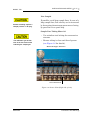
Unpacking the Unit...................................... 3-17
3.2.3
Model 700 Installation Arrangements............. 3-18
Wall Mount ................................................ 3-18
Pole Mount................................................. 3-19
Floor Mount................................................ 3-19
3.2.4
Required Tools and Components ................... 3-19
3.2.5
Supporting Tools and Components ................ 3-21
3.3
MODEL 700 INSTALLATION......................... 3-23
3.3.1
DC Power Supply ........................................ 3-23
3.3.2
Optional AC – DC Power Converter ............... 3-25
3.3.3
Sample and Gas Lines.................................. 3-28
3.4
SETTING THE COM ID ................................. 3-33
3.4.1
Inspect or Change the Com ID ...................... 3-33
3.4.2
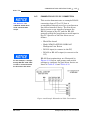
Preparing for Serial Connections.................... 3-37
3.4.3
FTB Connection (RS-232)............................. 3-40
3.4.4
PC to GC Cable Short Distance
Connection (RS-232) ................................... 3-41
3.4.5
Long Distance Connection (RS-422,
RS-485) ..................................................... 3-48
3.4.6
GC-Printer Wiring ........................................ 3-50
INSTALLATION AND SETUP
iv
TABLE OF CONTENTS
Model 700
3.4.7
Discrete Digital I/O Wiring ............................ 3-51
Discrete Digital Inputs.................................. 3-51
Discrete Digital Outputs ............................... 3-52
3.4.8
Analog Input Wiring..................................... 3-54
3.4.9
Analog Output Wiring .................................. 3-55
3.4.10 Optional
Optional
Optional
Ethernet
MAINTENANCE AND
TROUBLESHOOTING
Boards .......................................... 3-57
WinSystems Modem ....................... 3-57
Radicom Modem Settings ................ 3-58
Settings ........................................ 3-59
3.5
LEAK CHECKS AND PURGING FOR
FIRST CALIBRATION ................................... 3-60
3.5.1
Initial Leak Check ........................................ 3-60
Carrier Gas Line Leak Checks........................ 3-60
Calibration Line Leak Check .......................... 3-61
Sample Lines (Streams) Leak Check .............. 3-62
3.5.2
Purging Carrier Gas Lines ............................. 3-62
3.5.3
Purging Calibration Gas Lines........................ 3-64
3.6
SYSTEM STARTUP ..................................... 3-65
4.1
TROUBLESHOOTING AND REPAIR CONCEPT ... 4-1
4.2
ROUTINE MAINTENANCE............................... 4-1
4.2.1
Bimonthly Maintenance Checklist .................... 4-2
4.2.2
Routine Maintenance Procedures..................... 4-4
4.2.3
Contact Service ............................................ 4-4
4.3
ACCESS TO GC EQUIPMENT ELEMENTS ......... 4-5
4.3.1
Electrical/Electronic Components..................... 4-5
Model 700 with TCD Upper Enclosure ............. 4-6
Model 700 with TCD Lower Enclosure ............. 4-6
Model 700 with Micro-FID/TCD
Upper Enclosure............................................ 4-6
Model 700 with Micro-FID/TCD
Lower Enclosure ........................................... 4-6
4.3.2
Detector Elements, Heater Elements,
Valves and Columns ...................................... 4-7
MAINTENANCE AND TROUBLESHOOTING
SEP 2005
TABLE OF CONTENTS
Model 700
v
4.4
PRECAUTIONS FOR HANDLING
PC ASSEMBLIES ......................................... 4-11
4.5
GENERAL TROUBLESHOOTING..................... 4-12
4.5.1
Hardware Alarms ........................................ 4-12
4.5.2
Troubleshooting Checklist ............................ 4-14
4.5.3
Test Points Dual Methods Board and FTB ....... 4-19
4.5.4
Preamplifier ................................................ 4-22
4.5.5
Flow Balance Check .................................... 4-22
4.5.6
Temperature ............................................... 4-22
4.5.7
FID Configuration ........................................ 4-25
Baseline Drift .............................................. 4-26
4.6
LEAK CHECKS ............................................ 4-27
4.6.1
Field Service ............................................... 4-27
4.6.2
Factory Level Leak Check............................. 4-28
4.6.3
Plugged Lines, Columns, or Valves ................ 4-31
4.7
CHROMATOGRAPH VALVES........................ 4-31
4.7.1
Required Tools ............................................ 4-31
4.7.2
Chromatograph Valve Replacement Parts ....... 4-32
4.7.3
Valve Cleaning............................................ 4-32
4.7.4
TCD Oven System Removal.......................... 4-33
4.7.5
Micro-FID Removal ...................................... 4-36
4.7.6
Micro-FID Maintenance ................................ 4-39
4.7.7
Micro-FID Re-assembly................................. 4-39
4.7.8
Maintenance............................................... 4-41
4.7.9
LSIV Removal ............................................. 4-41
Replacing LSIV Seals ................................... 4-42
LSIV Disassembly........................................ 4-43
4.7.10 Methanator Maintenance.............................. 4-45
4.7.11 Valve Overhaul ........................................... 4-46
4.7.12 Oven System and Stream Switching
System Solenoid Valve Replacement ............. 4-48
SEP 2005
MAINTENANCE AND TROUBLESHOOTING
vi
TABLE OF CONTENTS
Model 700
4.7.13 Solenoid Valve Replacement ......................... 4-49
4.8
TCD DETECTOR BRIDGE BALANCE ............... 4-52
4.9
MEASURE VENT FLOW ............................... 4-55
4.10
MODEL 700 ELECTRICAL COMPONENTS ...... 4-56
4.10.1 DC Power Supply Replacement Procedures..... 4-59
4.11
COMMUNICATIONS .................................... 4-61
Model 700 GC with the TCD ........................ 4-61
Model 700 GC with the Micro-FID/TCD.......... 4-61
4.12
ANALOG INPUTS/OUTPUTS ......................... 4-65
4.12.1 Model 700 Analog Inputs ............................. 4-66
4.12.2 Analog Output Adjustment ........................... 4-67
4.12.3 Model 700 Analog Outputs .......................... 4-68
Standard Analog Outputs ............................. 4-68
4.13
DISCRETE DIGITAL INPUTS/OUTPUTS .......... 4-70
4.14
RECOMMENDED SPARE PARTS.................... 4-70
4.15
UPGRADE PROCEDURES ............................. 4-71
4.15.1 Base Operating System ................................ 4-71
4.15.2 Applications ............................................... 4-71
APPENDIX A,
COMMUNICATIONS
SPECIFICATIONS
A.1
TCD SERIAL COMMUNICATIONS....................A-1
A.1.1
Model 700 with a TCD Comm Ports ................A-2
A.2
FID SERIAL COMMUNICATIONS .....................A-7
A.2.1
Connecting Serial Communications to the GC .A-10
RS-232 Ports..............................................A-11
RS-422 Ports..............................................A-11
RS-485 Serial Specifications.........................A-11
APPENDIX A, COMMUNICATIONS SPECIFICATIONS
SEP 2005
TABLE OF CONTENTS
Model 700
SEP 2005
vii
A.2.2
FTB Serial Communications ..........................A-12
WinSystems CPU ........................................A-15
WinSystems MCM/LPM – Com4A Board ........A-19
Com4A Board Compatibility Settings .............A-23
WinSystems Ethernet Board .........................A-24
Radicom 56K Baud Modem Board .................A-25
A.3
WIRING LOCAL RS-232 COMMUNICATIONS..A-25
A.3.1
GC Serial Port and Cable Configurations.........A-25
A.3.2
GC DB 9-pin Serial Port to PC DB 9-pin Port ...A-29
A.3.3
GC DB 9-pin Serial Port to PC DB 25-pin Port .A-30
A.3.4
GC PHOENIX Plug Port to PC DB 9-pin Port ....A-31
A.3.5
GC PHOENIX Plug Port to PC DB 25-pin Port ..A-32
A.4
WIRING REMOTE RS-232
COMMUNICATIONS ....................................A-33
A.4.1
GC DB 9-pin Serial Port to Modem
DB 25-pin Port ............................................A-33
A.4.2
GC PHOENIX Plug to Modem
DB 25-pin Port ............................................A-34
A.5
EXAMPLE RS-422 PC-GC CONNECTION ........A-35
A.6
EXAMPLE RS-485 PC-GC CONNECTION ........A-37
APPENDIX A, COMMUNICATIONS SPECIFICATIONS
viii
TABLE OF CONTENTS
APPENDIX B, MODEM
INSTALLATION
APPENDIX C,
MANIFOLD CARRIER
FOR GAS BOTTLES
APPENDIX D,
ENGINEERING
DRAWINGS
Model 700
B.1
OPTIONAL INTERNAL MODEM ....................... B-1
B.1.1
Optional Ethernet Board ................................. B-3
C.1
CARRIER GAS ..............................................C-1
C.2
INSTALLATION AND LINE PURGING................C-2
C.3
REPLACING CARRIER CYLINDER ....................C-3
C.4
CALIBRATION GAS .......................................C-4
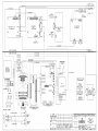
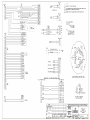
D.1
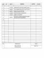
LIST OF ENGINEERING DRAWINGS .................D-1
Appendix B, MODEM INSTALLATION
SEP 2005
LIST OF FIGURES
Model 700
ix
LIST OF FIGURES
Figure 1-1
Block Diagram Upper Enclosure with TCD ........................................1-3
Figure 1-2
Block Diagram Upper Enclosure with Micro-FID.................................1-4
Figure 1-3
Block Diagram TCD Lower Enclosure ...............................................1-6
Figure 1-4
Block Diagram Micro-FID Lower Enclosure........................................1-7
Figure 1-5
Analyzer Assembly with TCD Detector Bridge ................................ 1-16
Figure 1-6
Detector Output During Component Elution .................................... 1-17
Figure 1-7
Analyzer Assembly with Micro-FID Detector Bridge ......................... 1-18
Figure 1-8
Model 700 LSIV Assembly ........................................................... 1-19
Figure 1-9
Model 700 Methanator Assembly ................................................. 1-21
Figure 2-1
Model 700 Gas Chromatograph ......................................................2-1
Figure 2-2
Upper Enclosure Assembly .............................................................2-2
Figure 2-3
TCD Oven System Assembly..........................................................2-3
Figure 2-4
Model 700 Micro-FID Upper Assembly.............................................2-4
Figure 2-5
Model 700 Methanator Upper Assembly ..........................................2-5
Figure 2-6
LSIV Assembly .............................................................................2-6
Figure 2-7
SSS Installed................................................................................2-7
Figure 2-8
Lower Enclosure Assembly.............................................................2-8
Figure 2-9
Upper Electronics with TCD Block Diagram .................................... 2-13
Figure 2-10
Upper Electronics with Micro-FID Block Diagram ............................. 2-14
Figure 2-11
Lower Electronics TCD Block Diagram ........................................... 2-15
Figure 2-12
Lower Electronics Micro-FID Block Diagram .................................... 2-16
Figure 3-1
Lower Enclosure Disassembly.........................................................3-5
Figure 3-2
Card Cage Cable Disassembly ........................................................3-6
Figure 3-3
Card Cage Assembly Screw Locations .............................................3-7
Figure 3-4
Card Cage Disassembly .................................................................3-8
Figure 3-5
Card Cage Disassembly for Power and Signal Wiring .........................3-9
Figure 3-6
Stream Inlets (Right side of unit)................................................... 3-15
Figure 3-7
DC Power Wiring ........................................................................ 3-24
SEP 2005
List of Figures
x
LIST OF FIGURES
Model 700
Figure 3-8
AC/DC Power Converter .............................................................. 3-26
Figure 3-9
Calibration Gas Stream Inlet (Right side of unit) .............................. 3-31
Figure 3-10
Sample Stream Inlets (Right side of unit) ....................................... 3-32
Figure 3-11
Dip Switch................................................................................. 3-33
Figure 3-12
Oven Mounting Bracket ............................................................... 3-34
Figure 3-13
Multifunction Board Location........................................................ 3-35
Figure 3-14
Dip Switch................................................................................. 3-35
Figure 3-15
Field Termination Board ............................................................... 3-41
Figure 3-16
Configuration without Com4A Board ............................................. 3-42
Figure 3-17
Configuration with Com4A Board
Figure 3-18
FTB Com1 and Com2 DB 9-pin Connector ..................................... 3-44
Figure 3-19
FTB Com 1 DB 9-pin Phoenix Connector........................................ 3-45
Figure 3-20
FTB Com2 DB 9-pin Phoenix Connector ......................................... 3-45
Figure 3-21
FTB Com5 DB 9-pin Phoenix Connector ......................................... 3-46
Figure 3-22
FTB Com6 DB 9-pin Phoenix Connector ......................................... 3-46
Figure 3-23
FTB Com7 DB 9-pin Phoenix Connector ......................................... 3-47
Figure 3-24
Com8 DB 9-pin Phoenix Connector GC Phoenix Plug Port ................ 3-47
Figure 3-25
GC Phoenix Plug Port to External Modem DB 25-pin Port ................. 3-48
Figure 3-26
Field Termination Board ............................................................... 3-51
Figure 4-1
Model 700 with TCD/Micro-FID Front View...................................... 4-5
Figure 4-2
CPU, Com4A, and Modem Boards .................................................. 4-7
Figure 4-3
Upper Explosion-proof Housing ....................................................... 4-8
Figure 4-4
Thermal Conductivity Detector ....................................................... 4-9
Figure 4-5
Flame Ionization Detector .............................................................. 4-9
Figure 4-6
Test Points Dual Methods Board (Cut View) ................................... 4-19
Figure 4-7
Test Points Dual Methods Board ................................................... 4-20
Figure 4-8
Test Points Field Termination Board (Cut View) .............................. 4-20
Figure 4-9
Test Points Field Termination Board .............................................. 4-21
Figure 4-10
Temperature Control Dialog.......................................................... 4-23
Figure 4-11
Chromatograph Valve Assemblies ................................................. 4-32
Figure 4-12
Micro-FID Oven System Thermal Cover ......................................... 4-33
Figure 4-13
TCD Upper Assembly Components ............................................... 4-34
List of Figures
............................................... 3-43
SEP 2005
Model 700
LIST OF FIGURES
xi
Figure 4-14
TCD Oven System Disassembly .................................................... 4-35
Figure 4-15
Micro-FID Upper Assembly Components ........................................ 4-37
Figure 4-16
Model 700 with Micro-FID Upper Assembly ................................... 4-38
Figure 4-17
Model 700 with LSIV .................................................................. 4-43
Figure 4-18
Model 700 Optional Methanator Assembly..................................... 4-45
Figure 4-19
TCD Valve Tubing and Fittings ..................................................... 4-47
Figure 4-20
Side View TCD Oven System Mounting Bracket ............................. 4-49
Figure 4-21
Rotated TCD Upper Assembly ...................................................... 4-50
Figure 4-22
Stream Switching Assembly......................................................... 4-51
Figure 4-23
Stream Switching System Final Assembly ...................................... 4-52
Figure 4-24
Model 700 Micro-FID/TCD Preamplifier .......................................... 4-53
Figure 4-25
Model 700 TCD Bridge Balance .................................................... 4-54
Figure 4-26
Model 700 Micro-FID Bridge Balance ............................................. 4-54
Figure 4-27
Measure Flow Vents ................................................................... 4-55
Figure 4-28
Model 700 Lower Enclosure ......................................................... 4-57
Figure 4-29
Model 700 Card Stack Assembly .................................................. 4-57
Figure 4-30
Model 700 Lower Assembly......................................................... 4-58
Figure 4-31
DC Power Supply Lower Enclosure................................................ 4-59
Figure 4-32
Dip Switch................................................................................. 4-62
Figure 4-33
Multifunction Board..................................................................... 4-63
Figure 4-34
Analog Board - Inputs.................................................................. 4-66
Figure 4-35
Analog Inputs............................................................................. 4-67
Figure 4-36
FTB Board Analog Outputs........................................................... 4-68
Figure 4-37
Analog Outputs .......................................................................... 4-69
Figure 4-38
Optional Analog Board Outputs..................................................... 4-69
Figure A-1
Standard Configuration without LOI and Com4A Board..................... A-3
Figure A-2
Configuration with LOI ................................................................. A-3
Figure A-3
Configuration with Com4A Board................................................... A-4
Figure A-4
Configuration with Com4A Board and LOI ....................................... A-5
Figure A-5
FTB Com1 and Com2 DB9 Connector............................................. A-6
SEP 2005
List of Figures
xii
LIST OF FIGURES
Model 700
Figure A-6
Configuration without Com4A Board ...............................................A-8
Figure A-7
Configuration with Com4A Board ...................................................A-9
Figure A-8
FTB Com1 DB 9-pin Phoenix Connector .........................................A-12
Figure A-9
FTB Com2 DB 9-pin Phoenix Connector........................................A-12
Figure A-10
FTB Com5 DB 9-pin Phoenix Connector .........................................A-13
Figure A-11
FTB Com6 DB 9-pin Phoenix Connector........................................A-13
Figure A-12
FTB Com7 DB 9-pin Phoenix Connector .........................................A-14
Figure A-13
FTB Com8 DB 9-pin Phoenix Connector .........................................A-14
Figure A-14
FTB Serial Connections................................................................A-26
Figure A-15
FTB Serial Connections................................................................A-26
Figure A-16
Phoenix Connector (J5, J6, J10, and J11) Pinout ...........................A-27
Figure A-17
DB 9-pin Connector (P2 and P3) and Pinout for Jacks .....................A-28
Figure A-18
GC DB 9-pin Port to PC DB 9-pin Port ...........................................A-29
Figure A-19
GC DB 9-pin Port to PC DB 25-pin Port..........................................A-30
Figure A-20
GC DB 9-pin Port to PC DB 25-pin Port..........................................A-31
Figure A-21
GC Phoenix Plug Port to PC DB 25-pin Port....................................A-32
Figure A-22
GC DB 9-pin Port to External Modem DB 25-pin Port .......................A-33
Figure A-23
GC Phoenix Plug Port to External Modem DB 25-pin Port .................A-34
Figure A-24
Example RS-422 Serial Cable Terminations ....................................A-35
Figure A-25
Example RS-485 Serial Cable Terminations, Line Driver
to GC Controller Com3 ................................................................A-37
Figure A-26
Example RS-485 Serial Cable Terminations, Line Driver to
GC Controller Com4....................................................................A-38
Figure B-1
Radicom 56K Baud Modem Installation ............................................ B-2
Figure C-1
Manifold for Two Carrier Gas Bottles to GC System ..........................C-1
List of Figures
SEP 2005
LIST OF TABLES
Model 700
xiii
LIST OF TABLES
Table 2-1
Model 700 Unit Specifications...................................................... 2-11
Table 2-2
Electronic Hardware Specification ................................................. 2-17
Table 2-3
Oven Assembly Specifications...................................................... 2-18
Table 2-4
Software Specifications ............................................................... 2-19
Table 3-1
DC Power Wiring ........................................................................ 3-24
Table 3-2
AC Wiring.................................................................................. 3-27
Table 3-3
Modbus Slave Address (Com ID) DIP Switch Settings...................... 3-36
Table 3-4
Switch Positions for Cold Start ..................................................... 3-37
Table 3-5
FTB Discrete Digital Inputs ........................................................... 3-52
Table 3-6
FTB Discrete Digital Outputs ........................................................ 3-53
Table 3-7
FTB Analog Inputs ...................................................................... 3-54
Table 3-8
FTB Analog Outputs.................................................................... 3-55
Table 3-9
Optional Analog Outputs.............................................................. 3-56
Table 3-10
J8 Modem Board Jumper Settings ................................................ 3-57
Table 3-11
J9 Modem Board Jumper Settings ................................................ 3-57
Table 3-12
J10 Modem Board Jumper Settings .............................................. 3-57
Table 3-13
J26 Radicom Modem Jumper Settings .......................................... 3-58
Table 3-14
J27Radicom Modem Jumper Settings ........................................... 3-58
Table 3-15
J30 Radicom Modem Jumper Settings .......................................... 3-58
Table 3-16
J31 Radicom Modem Jumper Settings .......................................... 3-58
Table 3-17
J1 PCM-NE2000 Ethernet Board Jumper Settings ........................... 3-59
Table 3-18
J2 PCM-NE2000 Ethernet Board Jumper Settings ........................... 3-59
Table 3-19
J3 PCM-NE2000 Ethernet Board Jumper Settings ........................... 3-59
Table 4-1
Maintenance Checklist...................................................................4-3
Table 4-2
Basic Hardware Troubleshooting via Alarms ................................... 4-12
Table 4-3
Troubleshooting Checklist ............................................................ 4-16
Table 4-4
Temperature Control Dialog.......................................................... 4-24
Table A-1
Matrix of Possible TCD Configurations Field Termination Board.......... A-1
SEP 2005
List of Tables
xiv
LIST OF TABLES
Model 700
Table A-2
Matrix of Possible FID Configurations Field Termination Board ............A-7
Table A-3
Communication with WinSystems CPU..........................................A-15
Table A-4
Communication with WinSystems CPU..........................................A-16
Table A-5
Communication with WinSystems CPU..........................................A-17
Table A-6
Communication with WinSystems CPU..........................................A-18
Table A-7
Communication with WinSystems MCM/LPM –
Com4A Board (Optional) ..............................................................A-19
Table A-8
J10 Jumper Settings...................................................................A-23
Table A-9
J7 Jumper Settings.....................................................................A-23
Table A-10
J8 Jumper Settings.....................................................................A-23
Table A-11
J9 Jumper Settings.....................................................................A-23
Table A-12
Ethernet Board Pin Settings..........................................................A-24
Table A-13
J26 Radicom Modem Jumper Settings ..........................................A-25
Table A-14
J27 Radicom Modem Jumper Settings ..........................................A-25
Table A-15
J30 Radicom Modem Jumper Settings ..........................................A-25
Table A-16
J31 Radicom Modem Jumper Settings ..........................................A-25
Table A-17
Serial Ports on Field Termination Board..........................................A-27
Table A-18
Switch Settings for LD485A-MP, RS-422 to GC .............................A-36
Table A-19
Jumper Settings for LD485A-MP, RS-422 to GC ............................A-36
Table A-20
Switch Settings for LD485A-MP, RS-485 to GC .............................A-39
Table A-21
Jumper Settings for LD485A-MP, RS-485 to GC ............................A-39
Table C-1
Contents of Example Calibration Gas...............................................C-4
List of Tables
SEP 2005
INTRODUCTION
Model 700
1-1
INTRODUCTION
1
This section describes the contents and purpose
of the Model 700 Gas Chromatograph System
Reference Manual, a description of the Model
700 system, an explanation of the theory of
operation, and a glossary of chromatograph
terminology.
Use this section to get acquainted with the
basic engineering of the Model 700 product.
1.1
DESCRIPTION OF MANUAL
The Model 700 Gas Chromatograph System
Reference Manual (P/N 3-9000-521) consists of
Installation, Operations, and Maintenance and
Troubleshooting Procedures. Also, included is
information about the MON2000 software
interface.
1.2
SYSTEM DESCRIPTION
The Model 700 is a high-speed gas
chromatograph (GC) system that is engineered
to meet specific field application requirements
based on typical natural gas stream
composition and anticipated concentration of
the selected components. In its standard
configuration, the Model 700 can handle up to
four streams: typically, three for sample and
one for calibration.
The Model 700 system consists of three major
parts: the Analyzer Assembly, Controller
Assembly, and Sample Conditioning System
(SCS).
Model 700 subsystems are: a Flame Ionization
Detector (Micro-FID), a Liquid Sample Injector
(LSIV) and a Methanator.
SEP 2005
Description of Manual
1-2
INTRODUCTION
Model 700
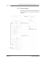
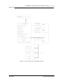
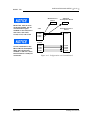
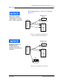
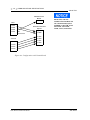
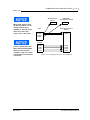
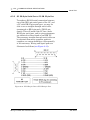
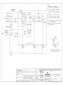
Analyzer Assembly
The Analyzer Assembly (upper enclosure)
includes columns TCD/Micro-FID detectors,
Methanator, preamplifier, preamplifier power
supply, stream switching valves, and solenoids.
See Figure 1-2 Block Diagram Upper
Enclosure for TCD details and Figure 1-5
Block Diagram Upper Enclosure for Micro-FID
details. Additionally, the Model 700 may be
equipped with the Liquid Sample Inject Valve
(LSIV) or a Methantor.
System Description
SEP 2005
Model 700
INTRODUCTION
1-3
Figure 1-1 Block Diagram Upper Enclosure with TCD
SEP 2005
System Description
1-4
INTRODUCTION
Model 700
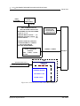
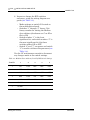
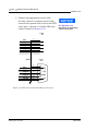
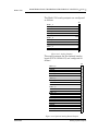
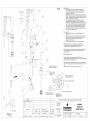
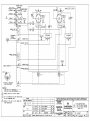
PREAMPLIFIER PCB
PREAMPLIFIER P/S PCB
DC-DC CONVERTERS
24VDC INPUT
24VDC
OUTPUTS
+20VDC -20VDC
100VDC
5VDC
POWER
INPUTS:
1 TCD DETECTOR
1 FID DETECTOR
OUTPUTS:
COM (1)
(RS-232 OR RS-485)
3.3 VDC
SERIAL I/O
SOLENOID/HEATER
DRIVER PCB
DC-DC CONVERTERS
24 VDC INPUT
OUTPUTS
5VDC
SOLENOID DRIVERS (16)
HEATERS (4 ZONES)
MULTIFUNCTION
MICRO-CONTROLLER PCB
SERIAL PORT RS-232
HEATER PWM CONTROLLER
(4 ZONES)
DIGITAL INPUTS.................(5)
COM RS-232......................(1)
RTD INPUTS.......................(4)
ANALOG INPUTS 4-20mA....(4)
DIGITAL OUTPUTS..............(5)
SERIAL DAC CONTROL........(SPI)
SERIAL PERIPHEERAL INTERFACE
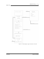
Figure 1-2 Block Diagram Upper Enclosure with Micro-FID
System Description
SEP 2005
INTRODUCTION
Model 700
1-5
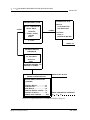
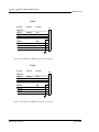
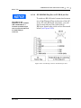
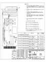
Controller Assembly
The Controller Assembly (lower enclosure)
includes electronics and ports for signal
processing, instrument control, data storage,
personal computer (PC) interface, and telecommunications. This assembly allows the user to
control the GC functions via a PC with the
MON2000 software package (see Section 1.3).
SEP 2005
System Description
1-6
INTRODUCTION
Model 700
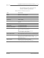
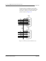
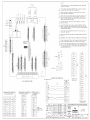
See Figure 1-3 and Figure 1-4 for lower
enclosure block diagrams.
Figure 1-3 Block Diagram TCD Lower Enclosure
System Description
SEP 2005
INTRODUCTION
Model 700
1-7
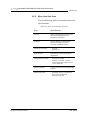
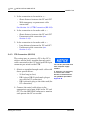
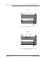
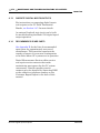
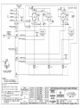
.
INPUT
AC POWER
OPTIONAL
AC-DC
POWER SUPPLY
24 VDC
FIELD TERMINATION PCB
OPTIONAL ANALOG
OUTPUT PCB
4 ISOLATED OR
8 NON-ISOLATED
BUILT IN SURGE PROTECTION
FIELD WIRING FOR THE FOLLOWING:
COM 1 & 2, 5-8
ANALOG INPUTS 4-20mA.......(4)
ANALOG OUTPUTS 4-20mA....(4)
DIGITAL INPUTS.....................(5)
DIGITAL OUTPUTS (5) RELAYS
2 RELAYS FORM “A” CONTACT
3 SOLID STATE RELAYS
ANALYZER INTERCONNECT
POWER FOR STANDARD BUS
DC-DC CONVERTER
OUTPUTS
5VDC, +12VDC, -12 VDC
SIGNALS - POWER
STD-BUS
- 3.8VDC
CPU
MULTIFUNCTION COM 3
FID & TCD PREAMPLIFIER COM 4
COM4A PCB
COM 5-8
ETHERNET PCB
INTERNAL MODEM
OPTIONAL PC104
BOARD STACK
Figure 1-4 Block Diagram Micro-FID Lower Enclosure
SEP 2005
System Description
1-8
INTRODUCTION
Model 700
The GC-PC interface provides the user with the
greatest capability, ease-of-use, and flexibility.
One PC running MON 2000 can connect with
up to 32 chromatographs (via RS-485 serial
communications links). MON 2000 is used to
edit applications, monitor operations, calibrate
streams, and display analysis chromatograms
and reports, which can then be stored to files
on the PC hard drive or printed from either the
PC printer port or the GC printer port.
Sample Conditioning System (SCS)
The sample conditioning system is located
between the process stream and the Analyzer
Assembly sample inlet (mounted on the lower
portion of the Analyzer Assembly stand). The
standard configuration includes a Stream
Switching System and filters.
The Model 700 electronics and hardware are
housed in two explosion-proof enclosures and
meet IEC Class I, Zone 1, Ex d IIB+H2, T4
(NEC Class 1, Division 1, Groups B, C, and D)
approval for use in a hazardous environment.
System Description
SEP 2005
INTRODUCTION
Model 700
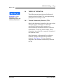
1.2.1
1-9
Functional Description
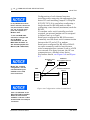
A sample of the gas to be analyzed is taken
from the process stream by a sample probe
installed in the process line. The sample passes
through a sample line to the SCS where it is
filtered or otherwise conditioned. After
conditioning, the sample flows to the Analyzer
Assembly for separation and detection of the
gas components.
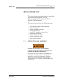
DANGER TO PERSONNEL AND EQUIPMENT
Do not use a PC or a printer in a hazardous area.
Serial port and Modbus communications links are
provided to connect the unit to the PC and to
connect to other computers and printers in a safe
area.
Failure to follow this warning may result in injury or
death to personnel or cause damage to the
equipment.
The chromatographic separation of the sample
gas into its components is accomplished in the
following manner. A precise volume of sample
gas is injected into one of the analytical
columns. The column contains a stationary
phase (packing) that is either an active solid or
an inert solid support that is coated with a
liquid phase (absorption partitioning). The
sample gas is moved through the column by
means of a mobile phase (carrier gas). The
selective retardation of the components takes
place in the column, causing each component to
move through the column at a different rate.
This separates the sample into its constituent
gases and vapors.
SEP 2005
System Description
1-10
INTRODUCTION
For additional information,
see Section 1.4
Model 700
A detector located at the outlet of the analytical
column senses the elution of components from
the column and produces electrical outputs
proportional to the concentration of each
component. Outputs from the detector(s) are
amplified in the Analyzer Assembly electronics,
then transmitted to the Controller Assembly
for further processing.
Output from the Controller Assembly is
normally displayed on a remotely located PC or
a printer. Connection between the Controller
Assembly and the PC can be accomplished via a
direct serial line or via a Modbus-compatible
communication interface.
Several chromatograms may be displayed via
MON2000, with separate color schemes,
allowing the user to compare present and past
data.
Use of the MON2000 software for configuration
and troubleshooting procedures is essential in
most cases. The PC may be remotely connected
via telephone, radio or satellite communications. Once installed and configured, the Model
700 can operate independently for long periods
of time.
System Description
SEP 2005
INTRODUCTION
Model 700
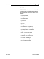
1.2.2
1-11
Available Functions
Individual GC functions that can be initiated or
controlled by the GC system and its software,
MON2000, include (but are not limited to) the
following:
• valve activations
• timing adjustments
• stream sequences
• calibrations
• baseline runs
• analyses
• halt operation
• stream/detector assignments
• stream/component table assignments
• stream/calculation assignments
• diagnostics
• alarm and event processing
• event sequence changes
• component table adjustments
• calculation adjustments
• alarm parameters adjustments
• analog scale adjustments
SEP 2005
System Description
1-12
INTRODUCTION
Model 700
Reports and logs that can be produced,
depending upon the GC application in use,
include (but are not limited to) the following:
• Configuration Report
• Parameter List
• Analysis Chromatogram
• Chromatogram Comparison
• Alarm Log (unacknowledged and active
alarms)
• Event Log
• Various Analysis Reports
System Description
SEP 2005
INTRODUCTION
Model 700
1.3
1-13
SOFTWARE DESCRIPTION
The MON2000 uses three distinct types of
software. This enables total flexibility in
defining the calculation sequence, printed
report content, format, type and amount of
data for viewing, control and/or transmission to
another computer or Controller Assembly. The
three types are:
• Baseline Operating System (BOS)
• Application configuration software
• Maintenance and Operations software
(MON2000 version 2.2 or later)
The BOS and the Application configuration
software are installed when the
Model 700 system is shipped. The application
configuration is tailored to the customer’s
process and shipped on a floppy disk. Note that
the hardware and software are tested together
as a unit before the equipment leaves the
factory. The MON2000 software program
communicates with the Model 700 system and
allows an initial site system setup (i.e.,
operational parameters, application
modifications, and maintenance).
BOS
The Baseline Operating System (BOS)
supervises operation of the Model 700 through
its internal microprocessor-based controller; all
direct hardware interface is via this control
software. It consists of a multi-tasking program
that controls separate tasks in system
operation, as well as hardware self-testing,
user application downloading, start-up, and
communications. Once configured, a Model 700
can operate as a stand alone unit.
SEP 2005
Software Description
1-14
INTRODUCTION
Model 700
MON2000
MON2000, available as a Windows-based
program, provides the human-machine
interface for maintenance, operation, and
troubleshooting. It allows the user to download
applications developed for a specific GC unit.
MON2000 provides operator control of the
connected Model 700, monitors analysis
results, and inspects and edits various
parameters that affect Model 700 operation. It
also controls display and printout of the
chromatograms and reports, and it stops and
starts automatic analysis cycling or calibration
runs.
After the equipment/software has been
installed and the operation stabilized,
automatic operation can be initiated. The link
between the MON2000 computer and the
Model 700 can either be direct, via a local serial
connection or remote, via an ethernet network,
modems, telephone lines and/or radio.
Operation of multiple Model 700
chromatographs (up to 32) with a single
MON2000 computer, via a multi-drop serial
link, is also supported.
Software Description
SEP 2005
INTRODUCTION
Model 700
1.4
See Section 1.7 for
definitions of the
terminology used in the
following explanations.
1-15
THEORY OF OPERATION
The following sections discuss the theory of
operation for the Model 700, the engineering
principles and concepts used.
1.4.1
Thermal Conductivity Detector (TCD)
One of the detectors (located on the oven in the
Analyzer upper assembly) is a thermal
conductivity detector that consists of a
balanced bridge network with heat sensitive
thermistors in each leg of the bridge. Each
thermistor is enclosed in a separate chamber of
the detector block.
One thermistor is designated the reference
element and the other the measurement
element. See Figure 1-5 for a schematic
diagram of the thermal conductivity detector
(TCD).
SEP 2005
Theory of Operation
1-16
INTRODUCTION
Model 700
Figure 1-5 Analyzer Assembly with TCD Detector Bridge
In the quiescent condition (prior to injecting a
sample), both legs of the bridge are exposed to
pure carrier gas. In this condition, the bridge is
balanced and the bridge output is electrically
nulled. (The bridge can be balanced by the fine
and coarse adjustment potentiometers located
on the preamplifier circuit board.)
The analysis begins when a fixed volume of
sample is injected into the column by operation
of the sample valve. The sample is moved
through the column by the continuous flow of
carrier gas. As successive components elute
from the column, the temperature of the
measurement element changes.
Theory of Operation
SEP 2005
INTRODUCTION
Model 700
1-17
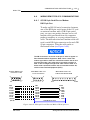
The temperature change unbalances the bridge
and produces an electrical output proportional
to the component concentration.
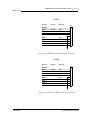
The differential signal developed between the
two thermistors is amplified by the
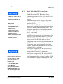
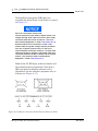
preamplifier. Figure 1-6 illustrates the change
in detector electrical output during elution of a
component.
3
1
2
1
1
detector bridge balanced
2
component begins to elute from column
and is measured by thermistor
3
peak concentration of component
Figure 1-6 Detector Output During Component Elution
In addition to amplifying the differential signal
developed between the two thermistors, the
preamplifier supplies drive current to the
detector bridge. The voltage signal is converted
to a 4-20 milliampere (mA) current loop for
transmission to the Controller Assembly.
The signal is proportional to the concentration
of a component detected in the gas sample. The
preamplifier provides four different gain
channels as well as compensation for baseline
drift.
SEP 2005
Theory of Operation
1-18
INTRODUCTION
Model 700
The signals from the preamplifier are sent to
the Controller Assembly for computation,
recording on a printer, or viewing on a PC
monitor (via MON2000).
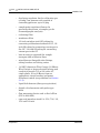
1.4.2
Flame Ionization Detector (Micro-FID)
The other detector (located on the oven in the
Analyzer Assembly) is a Flame Ionization
Detector. The Micro-FID requires a
polarization voltage and its output is connected
to the input to a high impedance amplifier
which is called an Electrometer. The burner
uses a mixture of hydrogen and air to maintain
the flame. The sample of gas to be measured is
also injected into the burner. See Figure 1-7 for
a schematic diagram of the Flame Ionization
Detector (Micro-FID).
Figure 1-7 Analyzer Assembly with Micro-FID Detector Bridge
Theory of Operation
SEP 2005
INTRODUCTION
Model 700
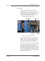
1.4.3
1-19
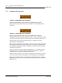
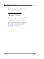
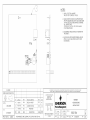
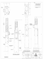
LSIV
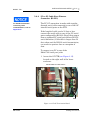
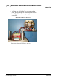
The Liquid Sample Inject Valve (LSIV)
penetrates the wall of the upper enclosure and
is held in place by a retaining ring. The
mounting arrangement is designed to ensure
integrity of the flameproof enclosure.
Model 700 LSIV Upper Enclosure
Retaining Ring
Piston Housing
Retraction
Air Inlet
Actuation
Air Inlet
Figure 1-8 Model 700 LSIV Assembly
The outermost end houses an air operated
piston. Air at 15 to 45 psi is directed by a
solenoid valve to either advance the stem to
inject the sample or to retract the stem.
The next section houses an auxiliary stem seal
assist. A piston driven by air at 80 to 100 psi
keeps adequate load on the stem seal to
counteract wear at the high temperatures and
pressures that might be encountered. There
are two ¼"npt ports in this section; one port
retracts the sample piston and the other port
activates the seal assist.
SEP 2005
Theory of Operation
1-20
INTRODUCTION
Model 700
The innermost section houses the stem seals
and the sample chamber. There are five ¼" npt
ports in this section.
Within the enclosure cavity are the flash
chamber components surrounded with
insulating covers. At working temperatures,
the surfaces of these covers become very hot to
the touch.
The tip of the LSIV is the port where flashed
sample is taken to the oven system.
The port at right angles to the length of the
LSIV is the input for carrier gas.
The heater block, a cylinder of aluminum, is
installed off-center surrounding the flash
chamber, close to the wall of the upper
enclosure. It houses the heater and an RTD
and is retained by a jamb nut that should only
be finger tight.
Theory of Operation
SEP 2005
INTRODUCTION
Model 700
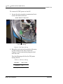
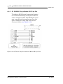
1.4.4
1-21
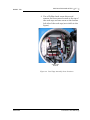
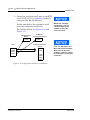
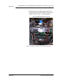
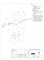
Methanator
After all other components have been
separated from the sample, normally
undetectable CO and CO2 are sent through the
methanator. They are combined with hydrogen
to make methane in a heat generated catalytic
reaction. The methanator is also known as a
methanizer or a catalytic converter.
Model 700 Methanator Upper Enclosure
Methanator
Assembly
Figure 1-9 Model 700 Methanator Assembly
SEP 2005
Theory of Operation
1-22
INTRODUCTION
Model 700
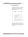
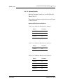
1.4.5
Data Acquisition
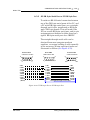
Every second, exactly 40 equi-spaced data
samples are taken (i.e., one data sample every
25 milliseconds) for analysis by the Controller
Assembly. The sampling frequency of 40 Hertz
(Hz) was chosen to reduce normal mode noise
(at 60 Hz).
After each point on the chromatograph signal is
sampled, the resulting number is stored for
processing in a buffer area of the Controller
Assembly memory. During the analysis, only
the last 256 data points are available for
processing.
Because the data analysis is done as the signal
is sampled (in real-time), only a limited
number of past data samples is required to
analyze any signal.
As a part of the data acquisition process,
groups of incoming data samples are averaged
together before the result is stored for
processing. Non-overlapping groups of N
samples are averaged and stored, and thus
reduce the effective incoming data rate to 40/N
samples per second. For example, if N = 5, then
a total of 40/5 or 6 (averaged) data samples are
stored every second.
The value for the variable N is determined by
the selection of a Peak Width parameter (PW).
The relationship is
N = PW
where PW is given in seconds. Allowable values
of N are 1 to 63; this range corresponds to PW
values of 2 to 63 seconds.
Theory of Operation
SEP 2005
INTRODUCTION
Model 700
1-23
The variable N is known as the integration
factor. This term is used because N determines
how many points are averaged, or integrated,
to form a single value. The integration of data
upon input, before storing, serves two
purposes:
• The statistical noise on the input signal is
reduced by the square root of N. In the case
of N = 4, a noise reduction of two would be
realized.
• The integration factor controls the
bandwidth of the chromatograph signal. It
is necessary to match the bandwidth of the
input signal to that of the analysis
algorithms in the Controller Assembly. This
prevents small, short-duration
perturbations from being recognized as true
peaks by the program. It is therefore
important to choose a Peak Width that
corresponds to the narrowest peak in the
group under consideration.
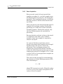
1.4.6
The Controller Assembly
software assumes that a
region of signal quiescence
and stability will exist.
SEP 2005
Peak Detection
For normal area or peak height concentration
evaluation, the determination of a peak's start
point and end point is automatic. The manual
determination of start and end points is used
only for area calculations in the Forced
Integration mode. Automatic determination of
peak onset or start is initiated whenever
Integrate Inhibit is turned off. Analysis is
started in a region of signal quiescence and
stability, such that the signal level and activity
can be considered as baseline values.
Theory of Operation
1-24
INTRODUCTION
Model 700
Having initiated a peak search by turning
Integrate Inhibit off, the Controller Assembly
performs a point by point examination of the
signal slope. This is achieved by using a digital
slope detection filter, a combination low pass
filter and differentiator. The output is
continually compared to a user-defined system
constant called Slope Sensitivity. A default
value of 8 is assumed if no entry is made.
Lower values make peak onset detection more
sensitive, and higher values make detection
less sensitive. Higher values (20 to 100) would
be appropriate for noisy signals, e.g. high
amplifier gain.
Onset is defined where the detector output
exceeds the baseline constant, but peak
termination is defined where the detector
output is less than the same constant.
Sequences of fused peaks are also
automatically handled. This is done by testing
each termination point to see if the region
immediately following it satisfies the criteria of
a baseline. A baseline region must have a slope
detector value less than the magnitude of the
baseline constant for a number of sequential
points. When a baseline region is found, this
terminates a sequence of peaks.
A zero reference line for peak height and area
determination is established by extending a
line from the point of the onset of the peak
sequence to the point of the termination. The
values of these two points are found by
averaging the four integrated points just prior
to the onset point and just after the
termination points, respectively.
Theory of Operation
SEP 2005
Model 700
INTRODUCTION
1-25
The zero reference line will, in general, be nonhorizontal, and thus compensates for any
linear drift in the system from the time the
peak sequence starts until it ends.
In a single peak situation, peak area is the area
of the component peak between the curve and
the zero reference line. The peak height is the
distance from the zero reference line to the
maximum point on the component curve. The
value and location of the maximum point is
determined from quadratic interpolation
through the three highest points at the peak of
the discrete valued curve stored in the
Controller Assembly.
For fused peak sequences, this interpolation
technique is used both for peaks, as well as,
valleys (minimum points). In the latter case,
lines are dropped from the interpolated valley
points to the zero reference line to partition the
fused peak areas into individual peaks.
The use of quadratic interpolation improves
both area and height calculation accuracy and
eliminates the effects of variations in the
integration factor on these calculations.
For calibration, the Controller Assembly may
average several analyses of the calibration
stream.
SEP 2005
Theory of Operation
1-26
INTRODUCTION
Model 700
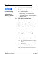
1.5
BASIC ANALYSIS COMPUTATIONS
Two basic analysis algorithms are included in
the Controller Assembly:
For additional information
about other calculations
performed, see the
MON2000 Software for Gas
Chromatographs User
Manual (P/N 3-9000-522).
• Area Analysis – calculates area under
component peak
• Peak Height Analysis – measures height of
component peak
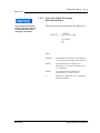
1.5.1
Conc Analysis - Response Factor
Concentration calculations require a unique
response factor for each component in an
analysis. These response factors may be
manually entered by an operator or determined
automatically by the system through
calibration procedures (with a calibration gas
mixture that has known concentrations).
The response factor calculation, using the
external standard, is:
Area
ARF n = --------------nCal n
or
Ht n
HRF n = ----------Cal n
where
Basic Analysis Computations
ARFn
area response factor for component “n” in area
per mole percent
Arean
area associated with component “n” in calibration gas
Caln
amount of component “n” in mole percent in
calibration gas
Htn
peak height associated with component “n”
mole percent in calibration gas
HRFn
peak height response factor for component “n”
SEP 2005
INTRODUCTION
Model 700
1-27
Calculated response factors are stored by the
Controller Assembly for use in the
concentration calculations, and are printed out
in the configuration and calibration reports.
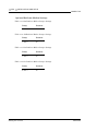
Average response factor is calculated as
follows:
k
∑ RFi
i=1
RFAVGn = -----------------k
where
RFAVGn
area or height average response factor for
component “n”
RFi
area or height average response factor for
component “n” from the calibration run
k
number of calibration runs used to
calculate the response factors
The percent deviation of new RF averages from
old RF average is calculated in the following
manner:
RF new – RF old
deviation = ----------------------------------- × 100
RF old
where the absolute value of percent deviation
has been previously entered by the operator.
SEP 2005
Basic Analysis Computations
1-28
INTRODUCTION
Model 700
1.5.2
Conc Calc - Mole Percentage
(without Normalization)
Once response factors have been determined by
the Controller Assembly or entered by the
operator, component concentrations are
determined for each analysis by using the
following equations:
Area
CONC n = --------------nARF n
or
Ht n
CONC n = -------------HRF n
where
ARFn
area response factor for component “n” in
area per mole percent
Arean
area associated with component “n” in
unknown sample
CONCn
concentration of component “n” in mole
percent
Htn
peak height associated with component “n”
mole percent in unknown sample
HRFn
peak height response factor for component
“n”
Component concentrations may be input
through analog inputs 1 to 4 or may be fixed. If
a fixed value is used, the calibration for that
component is the mole percent that will be used
for all analyses.
Basic Analysis Computations
SEP 2005
INTRODUCTION
Model 700
1.5.3
The average concentration
of each component will also
be calculated when data
averaging is requested.
1-29
Conc Calc in Mole Percentage
(with Normalization)
The normalized concentration calculation is:
CONC n
- × 100
CONCN n = --------------------------k
∑ CONCi
i=1
where
SEP 2005
CONCNn
normalized concentration of component
“n” in percent of total gas concentration
CONCi
non-normalized concentration of
component “n” in mole percent for each
“k” component
CONCn
non-normalized concentration of
component “n” in mole percent
k
number of components to be included in
the normalization
Basic Analysis Computations
1-30
INTRODUCTION
Model 700
1.6
ADDITIONAL RESOURCES
In addition to this manual, Model 700 Gas
Chromatograph System Reference Manual,
refer to the following:
• MON2000 Software for Gas
Chromatographs User Manual
(P/N 3-9000-522). Use this manual for
installing the MON2000 and Modbus Test
(WinMB) software programs, getting
started, checking various gas
chromatograph (GC) application settings,
and configuring and monitoring your GC
system.
Additional Resources
SEP 2005
INTRODUCTION
Model 700
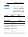
1.7
1-31
GLOSSARY
Auto Zero
Automatic zeroing of the TCD preamplifier
may be configured to take place at any time
during the analysis when either the component
is not eluting or the baseline is steady.
The Micro-FID is automatically zeroed at each
new analysis run and can be configured to take
place anytime during the analysis when either
the component is not eluting or the baseline is
steady. The TCD is only automatically zeroed
at the start of a new analysis.
Baseline
Signal output when there is only carrier gas
going across the detectors. In a chromatogram
you should only see Baseline when running an
analysis without injecting a sample.
Carrier Gas
The gas used to push the sample through the
system during an analysis. In C6+ analysis we
use Ultra Pure (zero grade) Carrier Gas for the
carrier. This gas is 99.995 percent pure.
Chromatogram
A permanent record of the detector output. A
chromatograph is obtained from a PC
interfaced with the detector output through the
Controller Assembly. A typical chromatogram
displays all component peaks, and gain
changes. It may be viewed in color as it is
processed on a PC VGA display. Tick marks
recorded on the chromatogram by the
Controller Assembly indicate where timed
events take place.
SEP 2005
Glossary
1-32
INTRODUCTION
Model 700
Component
Any one of several different gases that may
appear in a sample mixture
For example, natural gas usually contains the
following components: nitrogen, carbon dioxide,
methane, ethane, propane, isobutane, normal
butane, isopentane, normal pentane, and
hexanes plus.
Condulet
A box with a removable cover providing access
to wiring in conduit (conduit outlet) that is part
of an optional cable entry package.
CTS
Clear to send
DCD
Data carrier detect
DSR
Data set ready
DTR
Data terminal ready
Glossary
SEP 2005
INTRODUCTION
Model 700
1-33
FID
Flame Ionization Detector - The optional
Micro-FID may be used in place of one TCD for
the detection of trace compounds. The
Micro-FID requires a polarization voltage and
its output is connected to the input to a high
impedance amplifier, an Electrometer. The
sample of gas to be measured is injected into
the burner with a mixture of hydrogen and air
to maintain the flame.
LSIV
Liquid Sample Inject Valve - The optional LSIV
is used to convert a liquid sample to a gas
sample by vaporizing the liquid in a heated
chamber, then analyzing the flashed sample.
Methanator
The optional Methanator, a catalytic converter,
converts otherwise undetectable CO2 and/or
CO into methane by adding hydrogen and heat
to the sample.
Response Factor
Correction factor for each component as
determined by the calibration:
RawArea
RF = ---------------------------------------------------------------------CalibrationConcentration
Retention Time
Time (in seconds) that elapses between the
start of analysis (0 seconds) and the sensing of
the maximum concentration of each component
by the detector.
SEP 2005
Glossary
1-34
INTRODUCTION
Model 700
RI
Ring indicator
RLSD
Received Line Signal Detect (a digital
simulation of a carrier detect).
RTS
Request to send
RxD, RD, or Sin
Receive data, or signal in
TCD
Thermal Conductivity Detectors – Detectors
that use thermal conductivity of the different
gas components to produce an unbalanced
signal across the bridge of the preamplifier.
The higher the temperature the lower the
resistance on the detectors.
TxD, TD, or Sout
Transmit data, or signal out
Glossary
SEP 2005
EQUIPMENT DESCRIPTION AND SPECIFICATIONS
Model 700
2-1
EQUIPMENT DESCRIPTION AND SPECIFICATIONS
2
Use the following sections to reference the
Model 700 equipment description or specifications.
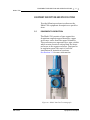
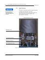
2.1
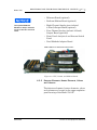
EQUIPMENT DESCRIPTION
The Model 700 consists of two copper-free
aluminium explosion-proof housings, upper
and lower, and a front flow panel assembly.
The enclosures are separated by a pipe conduit
which routes electrical wiring from the lower
enclosure to the upper enclosure. Designed to
be explosion-proof, this unit is built for
installation in hazardous locations.
See Section 3.1 for more information.
Figure 2-1 Model 700 Gas Chromatograph
SEP 2005
Equipment Description
2-2
EQUIPMENT DESCRIPTION AND SPECIFICATIONS
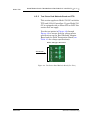
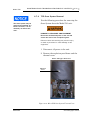
2.1.1
All circuit boards are
connected through a
common ground via the
enclosure.
Model 700
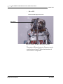
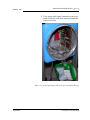
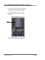
Upper Enclosure
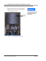
The Model 700 upper explosion-proof housing
contains the electronic controller
(multifunction board), the Oven System, the
Stream Switching System (SSS) and
preamplifier assembly.
Model 700 Upper Enclosure
Insulating Cover
Preamplifier Assembly
Multifunction Board
Micro-FID Exhaust Line
Figure 2-2 Upper Enclosure Assembly
Equipment Description
SEP 2005
Model 700
EQUIPMENT DESCRIPTION AND SPECIFICATIONS
2-3
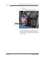
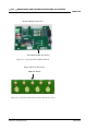
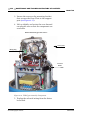
A more detailed equipment list includes:
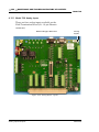
• TCD Oven System (consists of the
electronics, up to three chromatograph
valves and the stream switching system):
-
-
-
column module (i.e., “oven”)
one or two pairs thermal conductivity
detectors (TCDs)
valve system consisting of:
› three sample-directing valves
› plastic manifold that thermally
insulates the Oven System and
connects the actuating part to the
solenoid valves attached to the plastic
manifold
two heater zones: column with one
cartridge heater and one block with
three heaters
two thermal cut-off switches:
(oven temperature switch) opens at
257°F (±5 °) (125 °C)
Model 700 Upper Enclosure
Figure 2-3 TCD Oven System Assembly
SEP 2005
Equipment Description
2-4
EQUIPMENT DESCRIPTION AND SPECIFICATIONS
Model 700
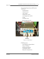
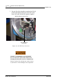
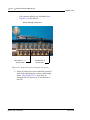
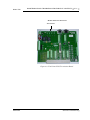
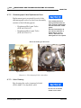
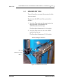
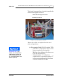
• Micro-FID
Model 700 FID Upper Enclosure
Micro-FID
Figure 2-4 Model 700 Micro-FID Upper Assembly
The optional Flame Ionization Detector may be
used in place of one TCD for the detection of
trace levels of compounds.
Equipment Description
SEP 2005
Model 700
EQUIPMENT DESCRIPTION AND SPECIFICATIONS
2-5
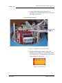
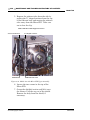
• Methanator
Model 700 Methantor Upper Enclosure
Methantor
Figure 2-5 Model 700 Methanator Upper Assembly
The optional Methanator, a catalytic converter,
converts otherwise undetectable CO2 and/or
CO into methane by adding hydrogen and heat
to the sample.
SEP 2005
Equipment Description
2-6
EQUIPMENT DESCRIPTION AND SPECIFICATIONS
Model 700
Model 700 LSIV Right Side View
LSIV Assembly
Figure 2-6 LSIV Assembly
The optional Liquid Sample Inject Valve (LSIV)
is used to convert a liquid sample to a gas
sample for analysis on the Model 700 Gas
Chromatograph.
A measured sample is placed in a heated
chamber above the vaporization point of the
liquid and then it is flashed to a gas. Once
vaporized, the sample is pushed by the carrier
gas through the heated tubing into the column
train.
Equipment Description
SEP 2005
Model 700
EQUIPMENT DESCRIPTION AND SPECIFICATIONS
2-7
• Stream Switching System (SSS) which
consists of:
-
manifold block
solenoid valves
valve clamps
temperature sensor
oven temperature switch
tubing
insulation cover
Model 700 Upper Enclosure
GC Valve
Solenoids
Figure 2-7 SSS Installed
• TCD Electronics
-
SEP 2005
Dual Methods Adapter Board
Driver I/O Board
Multifunction Board
Preamplifier Board
External Locking Device
Equipment Description
2-8
EQUIPMENT DESCRIPTION AND SPECIFICATIONS
Model 700
• Micro-FID Electronics
2.1.2
Solenoid/Heater Driver Board
Multifunction Board
Preamplifier Power supply
Driver I/O Board
Multifunction Board
Lower Enclosure
The Model 700 lower enclosure consists of:
Model 700 Lower Enclosure
AC/DC Power
Converter
FTB
Com1
Com2
Card Cage Assembly
(CPU, Analog,
Com4A, Modem,
Ethernet Cards)
Figure 2-8 Lower Enclosure Assembly
Equipment Description
SEP 2005
Model 700
EQUIPMENT DESCRIPTION AND SPECIFICATIONS
2-9
• Card cage assembly, containing:
DANGER TO PERSONNEL AND EQUIPMENT
See power supply label prior to connection.
Check the unit power design to determine if it
is equipped for AC or DC power. Applying 110/
220 VAC to a DC power input unit will
severely damage the unit.
Failure to do so may result in injury to
personnel or cause damage to the equipment.
The Model 700 CSAcertified unit is equipped
with 3/4 inch cross-over
adapters.
-
SEP 2005
WinSystems CPU board
Com4A board (optional)
analog board
analog board (optional)
digital I/O
internal modem (optional)
ethernet card (optional)
field termination board (FTB)
connection for AC/DC power supply
(converter)
internal and external ground
external locking device
DB pin connection for serial
communications
Equipment Description
2-10
EQUIPMENT DESCRIPTION AND SPECIFICATIONS
2.1.3
Model 700
Flow Panel Assembly
The Flow Panel Assembly is attached to the
front of the upper enclosure and consists of the
following: (see Figure 2-2):
If the carrier gas pressure
drops below a set point, this
switch causes the analysis
to stop and activates the
analyzer failure alarm.
• carrier pressure regulator(s) and gauge(s)
• sample flow meter
• Sample Vent (SV)
• Measure Vent (MV)
• actuation pressure limiting regulator
• pressure switch, mounted internally
2.2
EQUIPMENT SPECIFICATIONS
2.2.1
Utilities
Use the following table to determine the utility
specifications.
Equipment Specifications
SEP 2005
EQUIPMENT DESCRIPTION AND SPECIFICATIONS
Model 700
2-11
Table 2-1 Model 700 Unit Specifications
SEP 2005
Type
Specification
unit dimensions
(P/N 20351)
• basic unit envelope
w - 15.2” (387 mm)
h - 41.5” (1054 mm)
d - 19.2” (488 mm)
• wall mount
w - 18.2” (463 mm)
h - 41.5” (1054 mm)
d - 19.2” (488 mm)
• pole mount
w - 18.2” (463 mm)
h - 41.5” (1054 mm)
d - 25.0” (635 mm)
• floor mount
w - 18.2” (463 mm)
h - 58.0” (1470 mm)
d - 19.2” (488 mm)
Allow 14” (360 mm
additional) clearance for
removal of dome.
unit weight
• wall mount 130 lbs (59 kg)
• pole mount 135 lbs (61 kg)
• floor mount 150 lbs (68)
materials
• 303 and 316 stainless steel
• 316 stainless steel and Kapton in contact with sample
• Swagelock and Valco fittings
mounting
• floor mount
• pole mount:
- 2” (60.3 mm)
- 3” (89.0 mm)
- 4” (114.3 mm)
• direct wall mount
Equipment Specifications
2-12
EQUIPMENT DESCRIPTION AND SPECIFICATIONS
Model 700
Table 2-1 Model 700 Unit Specifications
Type
Specification
power
•
•
•
•
•
•
•
24 VDC standard
75W (Model 700 w/TCD)
150W (Model 700 w/Methanator
36VDC, Sol/Drv PCB Transorb
90-130/180-264 VAC
47-63HZ (single phase)
AC optional
or LSIV)
Voltage range includes line
voltage variations.
instrument air
not required; optional for valve
actuation, min pressure of 90 psig
environment
•
•
•
•
classification
• For Canada: Class 1,Zone 1,Ex d IIB (+H2),T4 (pending)
• For USA: Class 1,Zone 1,AEx d IIB (+H2),T4 (pending)
international
CENELEC/IEC Class 1,Zone 1, EEx d IIB(+H2) T4
(pending)
ATEX CE EEx d IIC T4
Certification number SIRA - 04ATEX1055X
Special conditions for safe use must be met. The
maximum constructional gap (ic) is less than that required
by Table 1 of IEC 60079-1:2004 as detailed below:
-18 to 55 oC (0 to 130 oF)
0 to 95% RH (non-condensing)
indoor/outdoor
pollution - degree 2 (the unit can withstand some non
conductive environmental pollutants e.g., humidity)
• max altitude 2000m
FLAMEPATH
MAXIMUM GAP (MM)
COMMENT
Fitting tube adaptor/fitting tube taper
0.000
Taper fit
Fitting tube/taper/tubes
0.132
Equipment Specifications
SEP 2005
Model 700
EQUIPMENT DESCRIPTION AND SPECIFICATIONS
2.2.2
2-13
Electronic Hardware
Review the system block diagrams, Upper and
Lower Electronics, to become familiar with the
Model 700.
Figure 2-9 Upper Electronics with TCD Block Diagram
SEP 2005
Equipment Specifications
2-14
EQUIPMENT DESCRIPTION AND SPECIFICATIONS
PREAMPLIFIER PCB
PREAMPLIFIER P/S PCB
24VDC
DC-DC CONVERTERS
24VDC INPUT
OUTPUTS
Model 700
POWER
+20VDC -20VDC
100VDC
5VDC
INPUTS:
1 TCD DETECTOR
1 FID DETECTOR
OUTPUTS:
COM (1)
(RS-232 OR RS-485)
3.3 VDC
SERIAL I/O
SOLENOID/HEATER
DRIVER PCB
DC-DC CONVERTERS
24 VDC INPUT
OUTPUTS
5VDC
SOLENOID DRIVERS (16)
HEATERS (4 ZONES)
MULTIFUNCTION
MICRO-CONTROLLER PCB
SERIAL PORT RS-232
HEATER PWM CONTROLLER
(4 ZONES)
DIGITAL INPUTS.................(5)
COM RS-232......................(1)
RTD INPUTS.......................(4)
ANALOG INPUTS 4-20mA....(4)
DIGITAL OUTPUTS..............(5)
SERIAL DAC CONTROL.........(SPI)
SERIAL PERIPHEERAL INTERFACE
Figure 2-10 Upper Electronics with Micro-FID Block Diagram
Equipment Specifications
SEP 2005
Model 700
EQUIPMENT DESCRIPTION AND SPECIFICATIONS
2-15
Figure 2-11 Lower Electronics TCD Block Diagram
SEP 2005
Equipment Specifications
2-16
EQUIPMENT DESCRIPTION AND SPECIFICATIONS
INPUT
AC POWER
Model 700
OPTIONAL
AC-DC
POWER SUPPLY
24 VDC
FIELD TERMINATION PCB
OPTIONAL ANALOG
OUTPUT PCB
4 ISOLATED OR
8 NON-ISOLATED
BUILT IN SURGE PROTECTION
FIELD WIRING FOR THE FOLLOWING:
COM 1 & 2, 5-8
ANALOG INPUTS 4-20mA.......(4)
ANALOG OUTPUTS 4-20mA....(4)
DIGITAL INPUTS.....................(5)
DIGITAL OUTPUTS (5) RELAYS
2 RELAYS FORM “A” CONTACT
3 SOLID STATE RELAYS
ANALYZER INTERCONNECT
POWER FOR STANDARD BUS
DC-DC CONVERTER
OUTPUTS
5VDC, +12VDC, -12 VDC
SIGNALS - POWER
STD-BUS
- 3.8VDC
CPU
MULTIFUNCTION COM 3
FID & TCD PREAMPLIFIER COM 4
COM4A PCB
COM 5-8
ETHERNET PCB
INTERNAL MODEM
OPTIONAL PC104
BOARD STACK
Figure 2-12 Lower Electronics Micro-FID Block Diagram
Equipment Specifications
SEP 2005
EQUIPMENT DESCRIPTION AND SPECIFICATIONS
Model 700
2-17
Use the following table to determine the
electronic hardware specifications.
Table 2-2 Electronic Hardware Specification
Type
Specification
Rating
Division 1; no purge required
CPU
WinSystems 386sx 33 MHz
Memory
4 MB System RAM
DiskOnChip
8 MB – 288 MB
Communication Ports
6 configurable Modbus ports; support RS-232/422/485
protocols
Optional Modem
56K Baud Telephone
Analog Inputs
4, 12-pin Phoenix on FTB
Standard Analog Outputs
4, 12-pin Phoenix on FTB
Optional Analog Outputs
8, non-isolated outputs 24-pin Phoenix
Located on Optional Analog Board
Or,
4, isolated outputs 12-pin Phoenix connector
Located on Optional Analog Board
Discrete Digital Inputs
GC_IN (dedicated to pressure switch); 4 user-defined inputs
Digital Outputs (5)
2 Relays “Form A” contacts
Relay contact rating 24 VDC nominal @ 1 Amp
3 Solid State Relays - Rating of 0.375A @30 VDC on FTB - 10
pin Phoenix connector
Detector Inputs
Optionally 2 micro-volume TCD inputs
1 Flame Ionization Detector (Micro-FID) input
Transient Protection
over-voltage category II
SEP 2005
Equipment Specifications
2-18
EQUIPMENT DESCRIPTION AND SPECIFICATIONS
2.2.3
Model 700
Micro Heat Sink Oven
Use the following table to determine the oven
specifications.
Table 2-3 Oven Assembly Specifications
Equipment Specifications
Type
Specification
Valves
6-port and 10-port valves; pistonoperated diaphragms with
pneumatic actuation
Columns
max of 40 feet (12 m) of micropacked columns; 1/16-inch
(1.6-mm) outside diameter
Solenoid Actuation
• 24 VDC
• max 90 psi
Wetted Parts
316 stainless steel and kapton
diaphragm
Temperature Control
• 24 VDC heat sink
• 2 zones (1 column, 1 block)
• max operating temperature of
115 °C (239 °F)
Sample System
1 zone, includes Stream Switching
System
Sample Streams
• standard: max of 3 analytical
and 1 auto calibration
• optional: max of 8
SEP 2005
Model 700
EQUIPMENT DESCRIPTION AND SPECIFICATIONS
2.2.4
Software
Use the following table to determine the
software specifications.
The Model 700 has its own
applications and is not
compatible with 2350/
2350A applications.
SEP 2005
2-19
Table 2-4 Software Specifications
Type
Specification
Software
PC-based MON2000; runs 2350 and
2350A applications (v2.4 or later)
Firmware
embedded firmware compatible with
2350/2350A applications (v1.8 or later)
Methods
4 Timed Event Tables and 4
Component Data Tables assignable to
each stream
Peak Integration
• fixed time or auto slope and peak
identification
• update Retention Time upon
calibration or during analysis
Equipment Specifications
2-20
EQUIPMENT DESCRIPTION AND SPECIFICATIONS
Model 700
This page is intentionally left blank.
Equipment Specifications
SEP 2005
INSTALLATION AND SETUP
MODEL 700
3-1
INSTALLATION AND SETUP
3-
This section provides instructions for installing
and setting up the Model 700 Gas
Chromatograph (GC) System for Zone 1/
Division I environments.
This procedure involves the following steps:
•
•
•
•
•
•
•
•
•
3.1
observe precautions and warnings
plan site location
obtain supplies and tools
install GC wiring
install GC sample and gas lines
perform leak checks
purge carrier gas lines
purge calibration lines
start up GC system
PRECAUTIONS AND WARNINGS
DANGER TO PERSONNEL AND EQUIPMENT
Install and operate all equipment as designed and is
compliant with all safety requirements.
The “Seller” does not accept any responsibility for
installations of the Model 700, or any attached
equipment, in which the installation or operation
thereof has been performed in a manner that is
negligent and/or non-compliant with applicable safety
requirements.
SEP 2005
Precautions and Warnings
3-2
INSTALLATION AND SETUP
3.1.1
Hazardous Environments
MODEL 700
DANGER TO PERSONNEL AND EQUIPMENT
Observe all precautionary signs posted on the Model 700 enclosure.
Failure to do so may result in injury to personnel or cause damage to the
equipment.
DANGER TO PERSONNEL AND EQUIPMENT
Observe all precautionary signs posted on the Model 700 enclosure.
The Model 700 enclosures are certified for Class 1, Zone 1, EEx d IIB (+H2)
T4 locations and also complies with the ATEX directive 94/9/EC EEx d IIC T4.
ATEX certified units must be installed strictly in compliance with the
requirements of ISO 60079-14.
Before opening the Model 700 assembly, reduce the risk of igniting hazardous
atmospheres by disconnecting the equipment from all power supplies. Keep
the assembly closed tightly when in operation to reduce the risk of igniting
hazardous atmospheres.
Inlet (incoming) wiring must meet local standards (i.e. in conduit with seal
fitting within 18” or via cable glands certified to ISO 60079-1). Seal all
unused entries with blanks certified to ISO 60079-1.
Observe all precautionary signs posted on the Model 700 enclosure. Failure to
do so may result in injury to personnel or cause damage to the equipment.
Please direct all health, safety and certification related questions to: Daniel
Measurement and Control, Inc. Applications Engineering Group or Rosemount
Analytical, Inc.
Precautions and Warnings
SEP 2005
INSTALLATION AND SETUP
MODEL 700
3-3
Follow these precautions if installing or
operating the Model 700 instrumentation in a
hazardous area:
1. Install and operate only the Zone 1/
Division I version of the Model 700 in a
hazardous area.
2. Do not operate any printer or personal
computer (PC) that is connected to a GC
which is installed in a hazardous area. To
interface with a GC in a hazardous area,
use a PC that is located in a nonhazardous
area and remotely connected to the GC.
3. Ensure that field connections to the
analyzer are made through explosion-proof
conduit or flameproof glands.
3.1.2
Power Source Wiring
Follow these precautions when installing AC
power source wiring:
1. All wiring must conform to the CEC or
NEC, local state or other jurisdiction, and
company standards and practices.
2. Provide 24 VDC power or optional singlephase, 3-wire, power at 115 or 230 VAC, 5060 Hertz.
3. Locate circuit breaker and optional power
disconnect switch in a safe area.
15 amps is the maximum
current for 14 AWG (wire).
SEP 2005
4. Provide the Model 700 system and any
optionally installed devices with one 15Amp circuit breaker for protection.
5. Ensure that the 24 VDC input power is
S.E.L.V. compliant by suitable electrical
separation from other circuits.
Precautions and Warnings
3-4
INSTALLATION AND SETUP
MODEL 700
6. Use multi-stranded copper conductor wire
according to the following recommendations:
• For power feed distances up to 250 feet
(76 meters), use 14 AWG (American
Wire Gauge) (18 Metric Wire Gauge),
stranded.
• For power feed distances 250 to 500 feet
(76 to 152 meters), use 12 AWG
(25 Metric Wire Gauge), stranded.
• For power feed distances 500 to 1000 feet
(152 to 305 meters), use 10 AWG
(30 Metric Wire Gauge), stranded.
• Cable entries are M32 in accordance
with ISO 965.
3.1.3
Card Cage Removal
The Model 700 card cage assembly is designed
to be disconnected and removed from the lower
enclosure to allow space for user power and
signal connections. This may be particularly
important for applications where large
numbers of I/O connections are required.
To disassemble the Card Cage,
1. Remove the lower enclosure cover and the
front flow panel assembly.
Precautions and Warnings
SEP 2005
INSTALLATION AND SETUP
MODEL 700
3-5
Note: Leave the wires attached to the flow
panel assembly and allow it to hang outside
of the enclosure.
Cover
Flow Panel
Figure 3-1 Lower Enclosure Disassembly
SEP 2005
Precautions and Warnings
3-6
INSTALLATION AND SETUP
MODEL 700
2. Carefully disconnect all of the ribbon cables
from the boards in the card cage assembly
(CPU, Analog, Modem, Ethernet, etc.).
Note the location of the
ribbon cables for ease
of reassembly.
Flow Panel
Figure 3-2 Card Cage Cable Disassembly
Precautions and Warnings
SEP 2005
MODEL 700
INSTALLATION AND SETUP
3-7
3. Use a Phillips head screw driver and
remove the two screws located at the top of
the card cage and one screw on the bottom
left side of the card cage (not visible in the
figure).
Card Cage
Screws
Figure 3-3 Card Cage Assembly Screw Locations
SEP 2005
Precautions and Warnings
3-8
INSTALLATION AND SETUP
MODEL 700
4. Slide the card cage assembly out of the
lower enclosure.
Figure 3-4 Card Cage Disassembly
Precautions and Warnings
SEP 2005
MODEL 700
INSTALLATION AND SETUP
3-9
5. User power and signal connections may be
made with the card cage removed from the
lower enclosure.
Figure 3-5 Card Cage Disassembly for Power and Signal Wiring
SEP 2005
Precautions and Warnings
3-10
3.1.4
INSTALLATION AND SETUP
MODEL 700
Signal Wiring
Follow these general precautions for field
wiring digital and analog input/output (I/O)
lines:
DANGER TO PERSONNEL AND EQUIPMENT
Observe all precautionary signs posted on the Model
700 enclosure. Applicable to all digital and analog I/O
lines connecting to the GC: Any loop of extra cable
left for service purposes inside the GC housing must
not be placed near any AC power lines.
If this precaution is not followed, the data and control
signals to and from the GC can be adversely affected.
• Metal conduit must be used for all process
signal wiring.
• Metal conduit or cable (in compliance with
EN 60079-14) used for process signal wiring
must be grounded at conduit support points
(intermittent grounding of conduit helps
prevent induction of magnetic loops
between the conduit and cable shielding).
• All process signal wiring should be a single,
continuous length between field devices and
the GC. If, however, length or conduit runs
require that multiple wiring pulls be made,
the individual conductors must be
interconnected with suitable terminal
blocks.
• Use suitable lubrication for wire pulls in
conduit to prevent wire stress.
• Use separate conduits for AC voltage and
DC voltage circuits.
• Do not place digital or analog I/O lines in
same conduit as AC power circuits.
Precautions and Warnings
SEP 2005
INSTALLATION AND SETUP
MODEL 700
3-11
• Use only shielded cable for digital I/O line
connections.
-
Ground the shield at only one end.
Shield-drain wires must not be more
than two AWG sizes smaller than the
conductors for the cable.
• When inductive loads (relay coils) are
driven by digital output lines, the inductive
transients must be diode-clamped directly
at the coil.
• Any auxiliary equipment wired to the GC
must have its signal common isolated from
earth/chassis ground.
3.1.5
Electrical and Signal Ground
Follow these general precautions for grounding
electrical and signal lines:
• For shielded signal conducting cables,
shield-drain wires must not be more than
two AWG sizes smaller than the conductors
for the cable. Shielding is grounded at only
one end.
• Metal conduit used for process signal wiring
must be grounded at conduit support points
(intermittent grounding of conduit helps
prevent induction of magnetic loops
between the conduit and cable shielding).
• A single-point ground (the outside case
ground lug) must be connected to a copperclad, 10-foot long, 3/4-inch diameter steel
rod, which is buried, full-length, vertically
into the soil as close to the equipment as is
practical (note: the grounding rod is not
furnished.)
SEP 2005
Precautions and Warnings
3-12
INSTALLATION AND SETUP
MODEL 700
• Resistance between the copper-clad steel
ground rod and the earth ground must not
exceed 25 Ohms.
• On ATEX certified units, the external
ground lug must be connected to the
customer’s protective ground system via
AWG 9 (6mm2) ground wire. After the
connection is made, apply a non-acidic
grease to the surface of the external ground
lug to prevent corrosion.
• The equipment-grounding conductors used
between the GC and the copper-clad steel
ground rod must be sized according to the
following specifications:
Length
Wire
15 ft. (4.6 m)
or less
8 AWG
stranded, insulated copper
15 to 30 ft.
(4.6 to 9.1 m)
6 AWG
stranded, insulated copper
30 to 100 ft.
(9.1 to 30.5 m)
4 AWG
stranded, insulated copper
• All inter-enclosure equipment-grounding
conductors must be protected by metal
conduit.
• External equipment, such as data printers,
that are connected to the GC should be
powered via isolation transformers to
minimize the ground loops caused by the
internally shared safety and chassis
grounds.
Precautions and Warnings
SEP 2005
INSTALLATION AND SETUP
MODEL 700
3.1.6
3-13
Electrical Conduit
Follow these general precautions for conduit
installation:
• Conduit cutoffs must be square. Cutoffs
must be made by a cold cutting tool,
hacksaw, or by some other approved means
that does not deform the conduit ends or
leave sharp edges.
• All conduit fitting-threads, including
factory-cut threads, must be coated with a
metal-bearing conducting grease, such as
Crouse-Hinds STL or equivalent, prior to
assembly.
• Temporarily cap the ends of all conduit runs
immediately after installation to prevent
accumulation of water, dirt, or other
contaminants. If necessary, swab out
conduits prior to installing the conductors.
• Install drain fittings at the lowest point in
the conduit run; install seals at the point of
entry to the GC explosion-proof housing to
prevent vapor passage and accumulation of
moisture.
• Use liquid-tight conduit fittings, such as
Myers Scru-tite or similar, for conduits
exposed to moisture.
SEP 2005
Precautions and Warnings
3-14
INSTALLATION AND SETUP
MODEL 700
When conduit is installed in hazardous areas
(e.g., areas classified as NEC Class I, Division
1, Groups B, C, and D), follow these general
precautions for conduit installation:
DANGER TO PERSONNEL AND EQUIPMENT
Observe all precautionary signs posted on the
equipment. Consult your company policies and
procedures and other applicable requirements
documents to determine wiring and installation
practices that are appropriate for hazardous areas.
Failure to do so may result in injury to personnel or
cause damage to the equipment.
• All conduit runs must have a fitting, which
contains explosion-proof sealing (potting)
located within 18 inches from the conduit
entrance to the explosion-proof housing.
• The conduit installation must be vapor
tight, with threaded hub fittings, sealed
conduit joints and gaskets on covers, or
other approved vapor-tight conduit fittings.
3.1.7
Sample System Requirements
Observe the following guidelines for installing
GC sample systems:
Precautions and Warnings
SEP 2005
INSTALLATION AND SETUP
MODEL 700
3-15
Line Length:
Stream switching requires a
sample pressure of 20 psig.
If possible, avoid long sample lines. In case of a
long sample line, flow velocity can be increased
by decreasing downstream pressure and using
by-pass flow via a speed loop.
Sample Line Tubing Material:
• Use stainless steel tubing for noncorrosive
streams.
The calibration gas stream
inlet is the last stream inlet
following the sample gas.
• Ensure tubing is clean and free of grease
(see Figure 3-6 for details).
Model 700 Upper Enclosure
Stream 1 - 8
Gas Connections
Figure 3-6 Stream Inlets (Right side of unit)
SEP 2005
Precautions and Warnings
3-16
INSTALLATION AND SETUP
MODEL 700
Dryers and Filters:
Use small sizes to minimize time lag and
prevent back diffusion.
-
-
Install a minimum of one filter to remove
solid particles. Most applications require
fine-element filters upstream of the GC.
The Model 700 hardware includes a 2
micron filter.
Do use ceramic or porous metallic type
filters. Do not use cork or felt filters.
Install the probe/regulator
first, immediately followed
by the coalescing filter and
then the membrane filter.
See Appendix C for a
recommended natural gas
installation.
Pressure Regulators and Flow Controllers:
-
Do not use types containing cork or felt
filters, or absorbent diaphragms.
Pipe Threads, Dressing:
-
Do use Teflon tape. Do not use pipe
thread compounds (dope).
Valving:
-
-
3.2
Install a block valve downstream of
sample takeoff point for maintenance
and shutdown.
Block valve should be needle valve or
cock valve type, of proper material and
packing, and rated for process line
pressure.
PREPARATION
Your Model 700 GC was started and checked
out before it left the factory. Program
parameters were installed and documented in
the PC Config Report furnished with your
Model 700.
Preparation
SEP 2005
INSTALLATION AND SETUP
MODEL 700
3.2.1
3-17
Site Selection
Install the GC as close as possible to the
sample system but allow for adequate access
space for maintenance tasks and adjustments.
Allow a minimum of 14 inches (36 cm) in front
for enclosure opening and access.
• Allow a minimum of 14 inches (36 cm) above
the top of the dome enclosure for dome
removal and access.
• Ensure that exposure to radio frequency
(RF) interference is minimal.
3.2.2
Unpacking the Unit
See the following checklist for unpacking the
unit and inspecting for damage:
1. Unpack the equipment:
• Model 700 system
• software and manuals
• documentation package
2. Ensure that all documentation and software
are included:
• this manual Model 700 Gas
Chromatograph System Reference
Manual (P/N 3-9000-521)
• the software manual, MON2000
Software for Gas Chromatographs User
Manual (P/N 3-9000-522)
• diskette(s) or CD-ROMs with the
MON2000 Software for Gas
Chromatographs Windows software
program, Modbus Test software
program, and GC applications
(P/N 2-3-2350-400)
SEP 2005
Preparation
3-18
INSTALLATION AND SETUP
MODEL 700
3. Remove any packing materials from
internal areas of the unit (particularly in
the dome enclosure).
Installation and startup should proceed only if
all required materials are on hand and free
from obvious defects.
If any parts or assemblies appear to have
been damaged in shipment, first file a claim
with the carrier. Next, complete a full report
describing the nature and extent of the damage
and forward this report immediately to Daniel
Measurement Services for further instructions
(see the Customer Repair Report at the back of
this manual). Include complete model number
information. Disposition instructions will be
returned immediately.
3.2.3
Model 700 Installation Arrangements
The Model 700 GC can be ordered for
installation in the following mounting
arrangements (see drawing P/N DE-20993):
-
wall mount
pole mount
floor mount
The wall should be strong
enough to support the 200
lb. load.
Wall Mount
The simplest arrangement is wall mount (see
drawing P/N DE-20993). The unit has two
mounting ears on each side. The ear-holes are
used to attach the unit to a wall.
The uppermost of the holes should be about 30
inches from the floor for the most efficient use
of the unit.
The space between the enclosures and the wall
(1.3 inches) allows adequate access above and
around the unit.
Preparation
SEP 2005
INSTALLATION AND SETUP
MODEL 700
3-19
Pole Mount
The pole mount arrangement uses mounting
ears as attachment points for the plates
clamped to a pole (see drawing P/N DE-20993).
The plates accept the recommended u-bolt
systems for the 2 inch, 3 inch or 4 inch nominal
pipe sizes. The base attachment of the pole
being used must be able to accommodate the
weight of the unit.
Floor Mount
The floor mount arrangement includes
additional external framing that creates a
free-standing unit (see drawing P/N DE20993). The mounting ears, located on the base
of the frame, are used to anchor the unit to a
floor or instrument pad. The frame, also
provides a means for attaching sampleconditioning plates or for anchoring
tubing-runs.
3.2.4
Required Tools and Components
You will need these tools and components to
install the Model 700:
• zero grade carrier gas (99.995% pure, with
less than 5 ppm water, and less than 0.5
ppm hydrocarbons)
• high pressure dual-stage regulator for the
carrier gas cylinder, high side up to 3000
pounds per square inch, gauge (psig), low
side capable of controlling pressure up to
150 psig
• calibration standard gas with correct
number of components and concentrations
(see Appendix Table C-1)
SEP 2005
Preparation
3-20
INSTALLATION AND SETUP
MODEL 700
• dual-stage regulator for the calibration gas
cylinder, low pressure side capable of
controlling pressure up to 30 psig
• sample probe regulator (fixture for
procuring the stream, or sample gas for
chromatographic analysis)
• coalescing filter
• membrane filter
• 1/8-inch stainless steel (SS) tubing for
connecting calibration standard to GC, 1/8
inch SS tubing for connecting carrier gas to
the GC, 1/8-inch SS tubing for connecting
stream gas to the GC
• heat tracing (as required) for sample
transport and calibration lines
• miscellaneous Swagelok tube fittings,
tubing benders and tubing cutter
• 14 AWG (American Wire Gauge) (18 Metric
Wire Gauge) or larger electrical wiring and
conduit to provide 115 or 230 volts AC,
single phase, 50 to 60 Hertz, from an
appropriate circuit breaker and power
disconnect switch (see guidelines in Section
3.1.2)
• liquid leak detector (Snoop or equivalent)
• digital volt-ohm meter with probe-type
leads
• flow measuring device such as Set-A-Flow
(P/N 4-4000-229)
• open-end wrenches sized 1/4, 5/16, 7/16, 1/2,
1/16 and 5/8-inch
Preparation
SEP 2005
INSTALLATION AND SETUP
MODEL 700
3.2.5
3-21
Supporting Tools and Components
DANGER TO PERSONNEL AND EQUIPMENT
Do not use a PC or a printer in a hazardous area.
Serial port and Modbus communications links are
provided to connect the unit to the PC and to
connect to other computers and printers in a safe
area.
Failure to follow this warning may result in injury
to personnel or cause damage to the equipment.
Supporting tools and components include:
• Use an IBM-compatible PC and either a
direct or remote communications connection
to interface with the Model 700 system. See
Section 2.1 of the MON2000 Software for
Gas Chromatographs User Manual
(P/N 3-9000-522) for more information on
specific PC requirements.
You can use the serial cable
installed for the Model 700.
For straight-through serial
cable installation and
fabrication instructions, see
Appendix A.
SEP 2005
• The Model 700 comes with serial Port 2 on
the Field Termination Board (FTB) factorywired with a DB 9-pin connection. Use the
provided serial cable (P/N 3-2350-068) to
hookup to a PC. See Table A-4 for more
information regarding these connections.
Preparation
3-22
INSTALLATION AND SETUP
MODEL 700
If a different serial cable is used to connect
from the PC to the pre-wired DB 9-pin,
follow these specifications:
Terminal
Connection
DB 9-pin male
Serial Port 2
DB 9-pin male
DB 25-pin female
PC serial port
• Use items necessary for connecting the GC
to a network or other type of remote data
transfer system (an example item might be
an RS-232/RS-485 conversion box for long
distance serial transmission), as applicable.
• Use a printer, connected either at the PC or
the GC unit, to record analysis and other
data. See Section 3.4.6 for wiring
information.
Preparation
SEP 2005
INSTALLATION AND SETUP
MODEL 700
3.3
MODEL 700 INSTALLATION
3.3.1
DC Power Supply
3-23
DANGER TO PERSONNEL AND EQUIPMENT
Ensure that the 24 VDC input power source is switched OFF
before connecting the wires. Also, ensure that the 24 VDC
input power is S.E.L.V. compliant by suitable electrical
separation from other circuits.
Failure to follow these warnings may result in injury or death
to personnel or cause damage to the equipment.
D
AMAGE TO EQUIPMENT
Check the unit prior to wiring to determine if it is equipped for
DC power.
Failure to observe this precaution may damage equipment.
SEP 2005
Model 700 Installation
3-24
INSTALLATION AND SETUP
MODEL 700
To connect 24 VDC power to the GC:
1. Locate the plug-together termination block
inside the lower enclosure.
Model 700 Lower Enclosure
DC Power Wiring
Figure 3-7 DC Power Wiring
2. Bring the two leads in through the left entry
on the bottom of the lower enclosure.
Connect to the termination plug provided
with the unit.
Use the following table for the DC power
wiring details:
Table 3-1 DC Power Wiring
Attribute
Wire Color
+ (positive)
red
– (negative)
black
Model 700 Installation
SEP 2005
INSTALLATION AND SETUP
MODEL 700
3-25
3. Each board that connects to the 24 VDC is
protected from lead reversal by the use of
blocking diodes. The following boards are
connected to the 24 VDC:
A new version of the
Solenoid/Heater Driver
Board that includes the
Diode protection will soon
be released.
•
•
•
•
Field Termination Board
Isolated Analog Output Option Board
Solenoid/Heater Driver board
Micro-FID/TCD Preamplifier Board
If the Red (+) and Black (-) leads are
inadvertently reversed, no damage will
occur, however, the system will not power
on.
4. Connect the DC power leads to the power
disconnect switch that is properly fused.
The recommended fuse size is 10 Amps.
3.3.2
Optional AC – DC Power Converter
To connect 115 or 230 VAC power to the GC:
DANGER TO PERSONNEL AND EQUIPMENT
Check the unit prior to wiring to determine if it is
equipped for optional AC power.
Failure to follow this warning may result in injury
to personnel or cause damage to the equipment.
SEP 2005
Model 700 Installation
3-26
INSTALLATION AND SETUP
MODEL 700
1. Locate the plug-together termination block
inside the lower enclosure (located on the
lower left side behind the power supply).
Model 700 Lower Enclosure
AC / DC Power
Converter
Figure 3-8 AC/DC Power Converter
DANGER TO PERSONNEL AND EQUIPMENT
Do not connect AC power leads without first
ensuring that AC power source is switched OFF.
Failure to follow this warning may result in injury
to personnel or cause damage to the equipment.
Model 700 Installation
SEP 2005
INSTALLATION AND SETUP
MODEL 700
3-27
DAMAGE TO EQUIPMENT
Do not apply electrical power to the GC until all
interconnections and external signal connections
have been verified, and proper grounds have
been made.
Failure to observe this precaution may cause
damage to equipment.
AC wiring is usually colored as:
Table 3-2 AC Wiring
Attribute
Wire Color
hot
brown or black
neutral
blue or white
ground
green or green
2. Bring the power leads in through the left
entry on the bottom of the enclosure.
3. If necessary, connect the GC chassis ground
to an external copper ground rod (at remote
locations). See Section 3.1.5 regarding
electrical and signal grounding.
SEP 2005
Model 700 Installation
3-28
3.3.3
INSTALLATION AND SETUP
MODEL 700
Sample and Gas Lines
To install GC sample and gas lines:
Use SS tubing. Keep tubing
1. Remove the plug from the Sample Vent (SV) clean and dry internally to
line (1/16-inch tubing marked “SV” located avoid contamination. Before
connecting the sample and
on the Flow Panel Assembly).
• If desired, connect the SV line to an
external (ambient pressure) vent. If the
vent line is terminated in an area
exposed to wind, protect the exposed
vent with a metal shield.
• Use 1/4-inch or 3/8-inch tubing for vent
lines longer than 10 feet.
gas lines, flow clean air or
gas through them. Blow out
internal moisture, dust, or
other contaminants.
Note that, at this stage in the installation,
the GC Measure Vent (MV) line (marked
“MV”) remains plugged until leak checks
are completed. For regular operation,
however, the MV line must be unplugged, or
open.
Do not discard the vent line plugs. They are
useful at any time when leak-checking the
GC and its sample or gas line connections.
Model 700 Installation
SEP 2005
INSTALLATION AND SETUP
MODEL 700
3-29
2. Connect carrier gas to the GC. (The carrier
gas inlet is a 1/8-inch tee fitting located on
the left side of the upper enclosure.)
MAY CAUSE INJURY TO PERSONNEL OR
EQUIPMENT DAMAGE
Do not turn on gas until you have completed
leak checking the carrier and sample lines (see
Step 5).
Failure to follow this precaution may cause
injury to personnel or damage equipment.
Model 700 Lower Enclosure
Carrier Gas
Inlet
• Use 1/8-inch or 1/4-inch stainless steel
tubing to conduct carrier gas.
• Use a dual-stage regulator with highside capacity of 3000 psig and low-side
capacity of 150 psig.
SEP 2005
Model 700 Installation
3-30
INSTALLATION AND SETUP
MODEL 700
• See Appendix C for a description of a
dual-cylinder carrier gas manifold
(P/N 3-5000-050) with these features:.
- Carrier gas is fed from two bottles.
The first stream is the
- When one bottle is nearly empty (100 calibration gas stream.
psig), the other bottle becomes the
primary supply.
- Each bottle can be disconnected for
refilling without interrupting GC
operation.
3. Connect calibration standard gas to the GC
• Use 1/8-inch stainless steel tubing to
conduct calibration standard gas.
• Use a dual-stage regulator with low-side
capacity of up to 30 psig.
Model 700 Installation
When installing the
calibration standard gas line,
ensure that the correct
tubing connection is made.
SEP 2005
MODEL 700
INSTALLATION AND SETUP
3-31
• The Calibration gas inlet is the last inlet
following the sample gas
(see Figure 3-9).
Model 700 Upper Enclosure
Calibration
Gas Inlet
Figure 3-9 Calibration Gas Stream Inlet (Right side of unit)
4. Connect sample gas stream(s) to the GC.
• Use 1/8-inch or 1/4-inch stainless steel
tubing to conduct calibration standard
gas.
• Ensure that pressure of sample line is
regulated to maintain 15 to 30 psig
(±10%).
SEP 2005
Model 700 Installation
3-32
INSTALLATION AND SETUP
MODEL 700
• Gas stream inlet(s) are identified (see
Figure 3-10) for details.
Model 700 Upper Enclosure
Streams 1 - 7
Gas Inlets
Calibration
Gas Inlet
Figure 3-10 Sample Stream Inlets (Right side of unit)
5. After all lines have been installed, proceed
with leak checking the carrier and sample
lines. See Section 3.5.1; note that it
requires the AC power to be turned on at
the GC.
Model 700 Installation
SEP 2005
INSTALLATION AND SETUP
MODEL 700
3.4
3-33
SETTING THE COM ID
The Model 700 Com ID is determined by dual
inline package (DIP) switch settings.
Follow the steps in this
section only if you wish to
do the following:
• Change the Com ID
setting.
• Visually inspect and verify
the DIP switch settings.
Figure 3-11 Dip Switch
In most cases, the Com ID configuration made
at the factory will not need to be changed. The
factory DIP switch settings produce a Com ID
of 1.
3.4.1
Note that the MON2000
software Com I.D.s will
override the hardware
settings. To use the
hardware Com I.D.
configuration, enter a zero
‘0’ in the MON2000 Com
I.D, settings. For details,
refer to MON2000 Software
for Gas Chromatographs
User Manual (P/N 3-9000522).
Inspect or Change the Com ID
To visually inspect and verify the DIP switch
settings or to change the Com ID settings on
the multifunction board,
1. Remove the dome from the upper enclosure.
MAY CAUSE INJURY TO PERSONNEL OR
EQUIPMENTDAMAGE
Use caution when accessing an enclosure. A
voltage of 115 to 230 VAC, along with various
DC voltages, are present.
Failure to follow this precaution may cause
injury to personnel or damage equipment.
2. Loosen the thumb screws on the Oven
System mounting plate.
SEP 2005
Setting the Com ID
3-34
INSTALLATION AND SETUP
MODEL 700
3. Carefully lift up the assembly and rotate so
that the enclosure opening is accessible.
Model 700 Upper Enclosure
Mounting Bracket
Thumb Screw
Figure 3-12 Oven Mounting Bracket
Setting the Com ID
SEP 2005
MODEL 700
INSTALLATION AND SETUP
3-35
4. Locate the multifunction board. It is
mounted on a bracket towards the center of
the upper enclosure.
Model 700 Upper Enclosure
Multifunction
Board
Figure 3-13 Multifunction Board Location
5. On the multifunction board, locate the
Modbus slave address (Com ID) DIP switch.
It is labeled “S1” and mounted on the lower
right corner of the board.
Figure 3-14 Dip Switch
SEP 2005
Setting the Com ID
3-36
INSTALLATION AND SETUP
MODEL 700
6. Inspect or change the DIP switch as
necessary, using the wiring diagram as a
guide (see Table 3-3).
• Make settings on switch S1 located on
the multifunction board.
• Switches “1” through “5” form a 5-bit
binary number for setting the Modbus
slave address (also known as Com ID or
Device ID).
• Switch number “1” is the least
significant bit, and switch number “5” is
the most significant bit. Set these
switches either ON or OFF.
• Switch “6” and “7” are spares and switch
“8” is used to cold start the processor (see
Table 3-4).
Use the GC maintenance records to document
any changes made to the switch settings.
Table 3-3 Modbus Slave Address (Com ID) DIP Switch Settings
Com ID
1
2
3
4
5
1
ON
OFF
OFF
OFF
OFF
2
OFF
ON
OFF
OFF
OFF
3
ON
ON
OFF
OFF
OFF
4
OFF
OFF
ON
OFF
OFF
5
ON
OFF
ON
OFF
OFF
6
SPARE
7
SPARE
8
COLD START
Setting the Com ID
SEP 2005
INSTALLATION AND SETUP
MODEL 700
3-37
Table 3-4 Switch Positions for Cold Start
8
3.4.2
Normal (Run)
OFF
Cold Start
ON
Preparing for Serial Connections
The method for operating a Model 700 system
is from a connected personal computer (PC).
The PC must be:
• Running MON2000 software (version 2.2 or
later). See the MON2000 User Manual
(P/N 3-9000-522) for more information.
• Connected to the Model 700 via a serial
link.
This section addresses the basic ways to wire a
serial connection between a PC and the GC
system.
SEP 2005
Setting the Com ID
3-38
INSTALLATION AND SETUP
MODEL 700
Before connecting a PC to the Model 700,
determine the following:
1. What serial ports are available at the PC?
When you select one, consider these points:
• Standard PC serial ports are type
RS-232.
• Usually there are two external serial
port jacks on a PC, located on the rear
panel. Most often, they are either DB-9
or DB-25 male (see below).
Model 700 software
upgrades may be installed
via any available Com Port.
• PC serial ports can be used by other
peripheral equipment attached to the
PC, such as a printer, mouse, or modem,
etc.
To determine which PC serial ports are
already being used by other equipment
and which port can be used for
connecting to the GC, note existing serial
connections, refer to your PC user
manual, and use diagnostic software
(such as Norton Utilities).
2. What serial ports are available at the GC?
The Model 700 without the Micro-FID
comes equipped with three serial ports
(standard), unless the customer needs a LOI
Interface connection, then only two com
ports are standard. The installation of the
optional Com4A board (with or without a
LOI) brings the total number of available
serial ports to six.
Setting the Com ID
SEP 2005
MODEL 700
INSTALLATION AND SETUP
3-39
When you select a serial port, consider these
points:
• Com1 and Com2 from the WinSystems
CPU board (J1) to Field Termination
board (J5 and J7) (standard
configuration)
• Com3 from WinSystems CPU board (J6)
to the multifunction board
• Com4 is reserved for the LOI (Local
Operator Interface), if installed.
The Model 700 with the Micro-FID comes
equipped with two serial ports (standard). The
installation of the optional Com4A board bring
the total number of available serial ports to six.
When you select a serial port, consider these
points:
• Com1 and Com2 from the WinSystems
CPU board (J1) to Field Termination
board (J5 and J7) standard configuration
• Com3 from WinSystems CPU board (J6)
to the multifunction board (J4)
• Com4 from the WinSystems board (J6) is
connected to the Micro-FID/TCD
Preamplifier board (J4)
For additional serial ports, the:
• Optional Com4A board may be installed
at the factory. Com5 through Com8 are
fully available to the user and are
factory-configured to RS-232 protocol.
See Appendix A for additional options
(RS-422/485).
• With the optional Com4A board
installed, six Com ports are available to
the user.
SEP 2005
Setting the Com ID
3-40
INSTALLATION AND SETUP
MODEL 700
3. Is the connection to be made in a …
• Short distance between the PC and GC?
• With temporary or permanent cable
connection?
See Section 3.4.3, FTB Connection (RS-232).
4. Is the connection to be made with a …
• Short distance between the PC and GC?
• Permanent cable connection (see
Section 3.4.4).
5. Is the connection to be made with a …
• Long distance between the PC and GC?
• Permanent cable connection (see
Section 3.4.5).
3.4.3
FTB Connection (RS-232)
The easiest way to connect a PC to the GC is
with an off-the-shelf, straight-through serial
cable connected to the GC serial port DB 9-pin
connector pre-wired on the FTB.
1. Obtain a straight-through serial cable with
these specifications:
• 50 feet long (or less)
• DB 9-pin or DB 25-pin female plug at
one end (for PC connection)
• DB 9-pin male plug at the other end (for
GC connection)
You can buy this cable from
most computer supply
retailers.
If, however, it is necessary
to custom-wire a cable
because of circumstances,
see guidelines provided in
Appendix B.
2. Connect the serial cable plugs to the
appropriate serial port jacks at the PC and
GC. Use the MON2000 software to monitor
and operate the GC as needed.
Setting the Com ID
SEP 2005
INSTALLATION AND SETUP
MODEL 700
3.4.4
For detailed information
concerning serial
communications, refer to
Appendix A.
3-41
PC to GC Cable Short Distance
Connection (RS-232)
The PC-GC connection is made with straightthrough serial cable connected to one of the GC
internal serial ports on the FTB.
If the length of cable can be 50 feet or less,
connect the serial cable to one of the GC serial
ports configured for RS-232. (Recall that output
from a standard PC serial port follows RS-232
serial definition.) Cable that is longer than 50
feet, when used for RS-232 serial transmission,
can result in spurious loss or corruption of
data.
To connect your PC to one of the
Model 700 serial port jacks:
1. Access the GC FTB (see Figure 3-15).
located on the right wall of the lower
enclosure.
Model 700 Lower Enclosure
FTB
Figure 3-15 Field Termination Board
SEP 2005
Setting the Com ID
3-42
INSTALLATION AND SETUP
MODEL 700
2. Choose an available serial port on the FTB
(see P/N CE-21157 in Appendix D) that is
configured for RS-232 protocol.
Unless specified by the customer, serial
ports are configured for RS-232.
For further details, see Figure 3-16 and
Figure 3-17.
Multifunction
Board
Com3
CPU
Com1
Com2
Com3
Com4
Model 700, standard
configuration, has two
communications ports
available on the FTB;
Com1 and Com2.
FID/TCD
Preamplifier Board
Com4
Field Termination
Board
Com1
Com2
Com5
Com6
Com7
Com8
Com 4 is dedicated to the
Micro-FID/TCD Preamplifier.
When the LOI becomes
available, it will use a video
board instead of a serial port
connection.
Figure 3-16 Configuration without Com4A Board
Setting the Com ID
SEP 2005
INSTALLATION AND SETUP
MODEL 700
Multifunction
Board
Com3
Model 700, with the Com
4A board installed, has six
communications ports
available on the FTB; Com1
and Com2, and Com5,
Com6, Com7, and Com8.
3-43
FID/TCD
Preamplifier Board
Com4
CPU
Field Termination
Board
Com1
Com2
Com3
Com4
Com1
Com2
Com4A
Com 4 is dedicated to the
Micro-FID/TCD Preamplifier.
When the LOI becomes
available, it will use a video
board instead of a serial port
connection.
SEP 2005
Com5
Com6
Com7
Com8
Com5
Com6
Com7
Com8
Figure 3-17 Configuration with Com4A Board
Setting the Com ID
3-44
INSTALLATION AND SETUP
MODEL 700
3. Connect the appropriate serial cable.
If using a direct 6 conductor serial cable,
connect the exposed cable leads to the FTB
serial port. A pinout of a female DB 9-pin
socket is shown in Figure 3-18.
See Appendix A for
instructions on fabricating
a direct serial cable.
Com1
P2
RI 1
DSR 1
RTS 1
RXD 1
CTS 1
TXD 1
DTR 1
DCD 1
5
9
4
8
3
7
2
6
1
Com2
P3
GND
RI 2
DSR 2
RTS 2
RXD 2
CTS 2
TXD 2
DTR 2
DCD 2
5
9
4
8
3
7
2
6
1
Figure 3-18 FTB Com1 and Com2 DB 9-pin Connector
Setting the Com ID
SEP 2005
INSTALLATION AND SETUP
MODEL 700
3-45
4. Field Termination Board serial
communications settings are shown in
Figure 3-19 through Figure 3-23.
Com1
RS-232
RS-485
RS-422
J5
DCD 1
RXD 1
TXD 1
DTR 1
TX/RX+
TX/RX-
TX+
TX-
1
2
3
4
5
DSR 1
RTS 1
CTS 1
RI 1
RX+
RX-
6
7
8
9
Figure 3-19 FTB Com 1 DB 9-pin Phoenix Connector
Com2
RS-232
RS-485
RS-422
J7
DCD 2
RXD 2
TXD 2
DTR 2
TX/RX+
TX/RX-
TX+
TX-
1
2
3
4
DSR 2
RTS 2
CTS 2
RI 2
5
RX+
RX-
6
7
8
9
Figure 3-20 FTB Com2 DB 9-pin Phoenix Connector
SEP 2005
Setting the Com ID
3-46
INSTALLATION AND SETUP
MODEL 700
Com5
RS-232
RS-485
RS-422
J9
RLSD 5
RXD 5
TXD 5
DTR 5
TX/RX+
TX/RX-
TX+
TX-
1
2
3
4
5
DSR 5
RTS 5
CTS 5
RI 5
RX+
RX-
6
7
8
9
Figure 3-21 FTB Com5 DB 9-pin Phoenix Connector
Com6
RS-232
RS-485
RS-422
RLSD 6
RXD 6
TXD 6
DTR 6
TX/RX+
TX/RX-
TX+
TX-
DSR 6
RTS 6
CTS 6
RI 6
J13
1
2
3
4
5
RX+
RX-
6
7
8
9
Figure 3-22 FTB Com6 DB 9-pin Phoenix Connector
Setting the Com ID
SEP 2005
INSTALLATION AND SETUP
MODEL 700
3-47
Com7
RS-232
RS-485
RS-422
RLSD 7
RXD 7
TXD 7
DTR 7
TX/RX+
TX/RX-
TX+
TX-
J17
1
2
3
4
5
DSR 7
RTS 7
CTS 7
RI 7
RX+
RX-
6
7
8
9
Figure 3-23 FTB Com7 DB 9-pin Phoenix Connector
Com8
RS-232
RS-485
RS-422
RLSD 8
RXD 8
TXD 8
DTR 8
TX/RX+
TX/RX-
TX+
TX-
DSR 8
RTS 8
CTS 8
RI 8
J18
1
2
3
4
5
RX+
RX-
6
7
8
9
Figure 3-24 Com8 DB 9-pin Phoenix Connector
GC Phoenix Plug Port
SEP 2005
Setting the Com ID
3-48
INSTALLATION AND SETUP
MODEL 700
To make an RS-232 serial connection between
one of the Phoenix Plug serial ports of the GC,
and an external modem with DB 25-pin serial
port, you will need to manufacture the cable
and its DB 25-pin, male plug cable end as
illustrated below (see Figure 3-25).
Figure 3-25 GC Phoenix Plug Port to External Modem
DB 25-pin Port
3.4.5
Long Distance Connection (RS-422, RS-485)
RS-422 and RS-485 serial protocols are
recommended for longer distance serial
connections between the PC and GC System
(i.e., distances greater than the 50 feet).
Setting the Com ID
SEP 2005
MODEL 700
INSTALLATION AND SETUP
3-49
To connect your PC to one of the internal
Model 700 RS-422/RS-485 serial port jacks:
5. Obtain the following equipment:
• An asynchronous line driver (or interface
device) with RS-232 input and RS-422/
RS-485 output. See Appendix A for
example brand and model.
• Shielded, computer-grade, twisted pair
cable (to connect the asynchronous line
driver device to the GC).
• A straight-through serial cable (to
connect the PC to the line driver).
6. Connect the straight-through serial cable
from the PC serial port to the RS-232 serial
port of the line driver device. Then connect
the twisted pair cable to the RS-422/RS-485
serial port of the line driver.
7. Configure the line driver for data
communications equipment (DCE)
operation. See Appendix A for an example
configuration.
8. Access the GC FTB (see Figure 3-15 in
Section 3.4.2).
Serial ports Com1 through
Com3 are configured by
default for RS-232.
For further details or
instructions on how to
configure these ports to RS422/485, see Appendix A.
SEP 2005
9. Choose an available serial port on FTB that
is configured for RS-422 or RS-485 serial
protocol, and connect the twisted pair cable
from the line driver. See Appendix A for
example connection. Also see Figure 3-19
through see Figure 3-23 for a list of ports
and terminals assigned for serial communications.
Setting the Com ID
3-50
3.4.6
INSTALLATION AND SETUP
MODEL 700
GC-Printer Wiring
A printer can be connected directly to the GC
the Field Termination Board (FTB) at one of
the serial ports. The type and scheduling of
reports produced at the GC printer are
determined by settings made in MON2000
(from the Reports menu, select GC Report
Request and/or GC Printer Control; see the
MON2000 Software for Gas Chromatographs
User Manual (P/N 3-9000-522) for more
information).
The GC uses only a generic
printer driver. The PC printer
allows more control and
better quality output.
To connect a printer to the GC serial port:
1. Access the GC FTB (see Figure 3-15 in
Section 3.4.2).
2. Choose an available serial port on the FTB
that is configured for RS-232 serial protocol.
3. After the wiring connections have been
completed, use MON2000 to configure the
GC serial port.
(a) From the Application menu, select Serial
Ports. The Serial Ports window appears.
(b) Select the appropriate Port row and set
Usage to “Report”, Protocol to “ASCII”
and RW to “W”.
(c) Ensure that the Com ID setting is
correct.
(d) Leave all other settings at the default
values (see the MON2000 User Manual
for more information).
Setting the Com ID
See Appendix A for a
complete listing of the serial
ports and corresponding
pinouts to fabricate a serial
printer cable.
SEP 2005
INSTALLATION AND SETUP
MODEL 700
3.4.7
3-51
Discrete Digital I/O Wiring
The Field Termination Board (P/N 3-0700-010)
has five discrete outputs and four discrete
inputs.
Discrete Digital Inputs
To connect digital signal input/output lines to
the GC (P/N 3-0700-010):
1. Access the FTB (see Figure 3-26)
(P/N 3-0700-010).
Model 700 Lower Enclosure
J14
J10
Figure 3-26 Field Termination Board
The FTB has five discrete outputs and four
discrete inputs. The discrete input,
DIG_IN4, is dedicated to a pressure switch.
The discrete inputs are located on J10 (10
pin Phoenix connector).
SEP 2005
Setting the Com ID
3-52
INSTALLATION AND SETUP
MODEL 700
2. Route digital I/O lines appropriately,
especially in the case of the explosion-proof
enclosure.
There are connections for four digital inputs
and five digital output lines (Phoenix 10-pin
connector), as follows:
Table 3-5 FTB Discrete Digital Inputs
J10
Function
Description
Pin 1
DIG_IN1
Pin 2
GND
Pin 3
DIG_IN2
Pin 4
GND
Pin 5
DIG_IN3
Pin 6
GND
Pin 7
DIG_IN4
dedicated to a pressure switch
Pin 8
GND
dedicated to a pressure switch
Pin 9
DIG_IN5
Pin 10
GND
to customer
Discrete Digital Outputs
The discrete outputs are located on J14
(P/N 3-0700-010) (Phoenix 10-pin connector)
have two “Form A” relays on the FTB. Outputs
3-5 are Solid State switches with a rating of
.375A @30 VDC. The relays, with sealed
enclosures, have a contact current rating of 1.0
Amperes each (see Figure 3-26).
Setting the Com ID
SEP 2005
INSTALLATION AND SETUP
MODEL 700
3-53
For discrete digital outputs, see Table 3-6.
Table 3-6 FTB Discrete Digital Outputs
SEP 2005
J14
Function
Pin 1
DIG_OUT
Pin 2
DIG_OUT
Pin 3
DIG_OUT
Pin 4
DIG_OUT
Pin 5
DIG_OUT_ 3+
Pin 6
DIG_OUT_ 3-
Pin 7
DIG_OUT_ 4+
Pin 8
DIG_OUT_ 4-
Pin 9
DIG_OUT_ 5+
Pin 10
DIG_OUT_ 5-
Setting the Com ID
3-54
3.4.8
INSTALLATION AND SETUP
MODEL 700
Analog Input Wiring
There are four analog inputs on the Field
Termination Board (P/N 3-0700-010 and
drawing CE-21157) located at J4 (12-pin
Phoenix connector).
Table 3-7 FTB Analog Inputs
Setting the Com ID
J4
Function
Pin 1
VIN+_1
Pin 2
VIN-_1
Pin 3
Shield
Pin 4
VIN+_2
Pin 5
VIN-_1
Pin 6
Shield
Pin 7
VIN+_3
Pin 8
VIN-_1
Pin 9
Shield
Pin 10
VIN+_4
Pin 11
VIN-_1
Pin 12
Shield
SEP 2005
INSTALLATION AND SETUP
MODEL 700
3.4.9
3-55
Analog Output Wiring
There are four standard analog outputs on the
standard FTB (P/N 3-0700-010 and drawing
CE-21157); located at J8 (12-pin Phoenix
connector). Additionally, if installed, the
optional analog board has eight analog outputs
Table 3-8 FTB Analog Outputs
J8
Function
Pin 1
IOUT+_1
Pin 2
IOUT-_1
Pin 3
Shield
Pin 4
IOUT+_2
Pin 5
IOUT-_2
Pin 6
Shield
Pin 7
IOUT+_3
Pin 8
IOUT-_3
Pin 9
Shield
Pin 10
IOUT+_4
Pin 11
IOUT-_4
Pin 12
Shield
There are eight analog outputs on the optional
analog output board (P/N 2-3-0580-037 and
drawing CE-21157); located at J3 (24-pin
Phoenix connector):
SEP 2005
Setting the Com ID
3-56
INSTALLATION AND SETUP
MODEL 700
Table 3-9 Optional Analog Outputs
Setting the Com ID
J3
Function
Pin 1
IOUT+_5
Pin 13
IOUT-_5
Pin 2
Shield
Pin 14
IOUT+_6
Pin 3
IOUT-_6
Pin 15
Shield
Pin 4
IOUT+_7
Pin 16
IOUT-_7
Pin 5
Shield
Pin 17
IOUT+_8
Pin 6
IOUT-_8
Pin 18
Shield
Pin 7
IOUT+_9
Pin 19
IOUT-_9
Pin 8
Shield
Pin 20
IOUT+_10
Pin 9
IOUT-_10
Pin 21
Shield
Pin 10
IOUT+_11
Pin 22
IOUT-_11
Pin 11
Shield
Pin 23
IOUT+_12
Pin 12
IOUT+_12
Pin 24
Shield
SEP 2005
INSTALLATION AND SETUP
MODEL 700
3-57
3.4.10 Optional Boards
Optional modem boards are available for the
Model 700 GC.
The jumper settings and pinouts for each board
is shown below.
Optional WinSystems Modem
Table 3-10 J8 Modem Board Jumper Settings
Pin(s)
Position
1 and 2
In
3 and 4
In
5 and 6
In
7 and 8
In
Table 3-11 J9 Modem Board Jumper Settings
Pin(s)
Position
1 and 2
In
5 and 6
In
Table 3-12 J10 Modem Board Jumper Settings
SEP 2005
Pin(s)
Position
1 and 2
In
3 and 4
In
5 and 6
In
9 and 10
In
15 and 16
In
Setting the Com ID
3-58
INSTALLATION AND SETUP
MODEL 700
Optional Radicom Modem Settings
Table 3-13 J26 Radicom Modem Jumper Settings
Pin(s)
Position
1 and 2
In
Table 3-14 J27Radicom Modem Jumper Settings
Pin(s)
Position
1 and 2
In
Table 3-15 J30 Radicom Modem Jumper Settings
Pin(s)
Position
1 and 2
In
Table 3-16 J31 Radicom Modem Jumper Settings
Pin(s)
Position
2 and 3
In
Setting the Com ID
SEP 2005
INSTALLATION AND SETUP
MODEL 700
3-59
Ethernet Settings
Table 3-17 J1 PCM-NE2000 Ethernet Board Jumper Settings
Pin(s)
Position
15 and 16
In
17 and 18
In
21 and 22
In
Table 3-18 J2 PCM-NE2000 Ethernet Board Jumper Settings
Pin(s)
Position
1 and 2
In
Table 3-19 J3 PCM-NE2000 Ethernet Board Jumper Settings
SEP 2005
Pin(s)
Position
1 and 2
In
7 and 8
In
Setting the Com ID
3-60
3.5
INSTALLATION AND SETUP
MODEL 700
LEAK CHECKS AND PURGING FOR
FIRST CALIBRATION
Apply AC power to the unit after verifying all
electrical connections are correct and safe.
Ensure that all interconnections and external
signal connections have been verified and
proper grounds have been made before turning
on the power.
3.5.1
Initial Leak Check
The focus of this section is for field connections
to the analyzer, during the installation process.
See Section 4.6 for an in depth discussion of
analyzer leak checks.
Carrier Gas Line Leak Checks
1. Plug the Measure Vent (labeled “MV”) to
block the free flow of Carrier Gas through
the GC.
2. Slowly pressurize the “GC side” of the
Carrier Gas to 110 psig (±2 percent) with
the dual-stage regulator at the Carrier Gas
cylinder.
The GC does not have an
inline Block Valve to shut
off the Carrier Gas flow.
3. After two minutes, shut off the Carrier Gas
bottle valve by turning it clockwise. Then,
observe the high-side regulator gauge on the
Carrier Gas bottle.
• The gauge should not bleed down more
than 200 psig in 10 minutes.
• If Carrier Gas is lost at a faster rate,
then all tube fittings between the
Carrier Gas bottle and the GC (including
the dual-stage regulator) must be
checked for leaks and tightened if
necessary.
Leak Checks and Purging FOR First Calibration
SEP 2005
MODEL 700
INSTALLATION AND SETUP
3-61
Most leaks at this stage (Installation and
Setup) are usually found between the
Carrier Gas bottle and the GC.
The dual-stage regulator fitting
connecting to the Carrier bottle, may not
seat properly with some Carrier Gas
bottles and allow a leak. If this occurs,
carefully wrap a small length of Teflon
tape around the tip of the inlet tube on
the dual-stage regulator (which sits
against the Carrier Gas bottle valve
seat).
4. Once the GC passes the “Initial leak check”,
reopen the Carrier Gas bottle valve and
remove the Measurement Vent (MV) plug.
Calibration Line Leak Check
1. Slowly pressurize the Calibration line (up to
20 psig).
2. Block-in the line by turning the “Cal
Stream” blocking valve clockwise until
seated.
3. Shut off the Calibration gas at the gas bottle
by turning the valve clockwise.
4. Observe the high-side of the Calibration gas
dual-stage regulator making sure the
pressure holds. The pressure should not
decrease for a period of two to three
minutes.
5. When the GC passes the “Initial Calibration
Gas leak check”, re-open the Calibration gas
bottle valve and the in-line “Cal Stream”
block valve.
SEP 2005
Leak Checks and Purging FOR First Calibration
3-62
INSTALLATION AND SETUP
MODEL 700
Sample Lines (Streams) Leak Check
1. Slowly pressurize the Sample line (up to 20
psig).
2. Block-in the line.
3. Observe the regulator, making sure the
pressure holds. The pressure should not
decrease for a period of two to three
minutes.
4. When the GC passes the “Initial Sample
Gas leak check”, re-open the Sample Gas
lines.
3.5.2
Purging Carrier Gas Lines
Purging carrier and calibration gas lines
requires AC power.
To purge the Carrier Gas lines,
1. Ensure that the MV vent line plug has been
removed, and the vent line is open.
2. Ensure that the Carrier Gas bottle valve is
open.
Tubing should be clean and
dry internally. During
installation, the tubing
should have been blown
free of internal moisture,
dust, or other contaminants.
3. Set the Carrier Gas line pressure at 110
psig. Use the dual stage regulator at the
Carrier Gas bottle to adjust pressure.
4. Turn ON the AC power to the GC.
5. Establish communications with the GC via
the MON2000 software. (Use the File >
Quick Connect menu path; see Section 2.7.2
in the MON2000 Software for Gas
Chromatographs User Manual
(P/N 3-9000-522) for more information.)
Leak Checks and Purging FOR First Calibration
Do not use the “Carrier
Pressure Adjust” regulator
adjustment (on the Flow
Panel Assembly) to adjust
Carrier Gas line pressure.
This pressure is factory-set
and should not be adjusted.
SEP 2005
MODEL 700
A period of 4 to 8 hours (or
overnight) is recommended,
during which all of the
settings described in Steps
1 through 7 are maintained.
No other settings should be
made.
INSTALLATION AND SETUP
3-63
6. Use the Applications>Temperature Control
menu path to access this function. The
readouts of the block, column and SSS
heater controllers should indicate that the
unit is warming up. Also, the yellow and red
status indicators on the FTB4 should be on.
7. Allow the GC system temperature to
stabilize and the Carrier Gas lines to
become fully purged with Carrier Gas.
8. Select the Auto Sequence Function. Use the
Control > Auto Sequence menu path
described in Section 4 of the MON2000
Software for Gas Chromatographs User
Manual (P/N 3-9000-522).
SEP 2005
Leak Checks and Purging FOR First Calibration
3-64
3.5.3
INSTALLATION AND SETUP
MODEL 700
Purging Calibration Gas Lines
To purge the calibration gas lines, as
preparation for first calibration:
1. Ensure that the Carrier Gas lines have been
fully purged, as described in the previous
section, and that the SV plug has been
removed.
2. Close the calibration gas bottle valve.
3. Fully open the block valve associated with
calibration gas feed (the block valve should
be located on lower right-hand corner of the
front panel).
See Section 5.8 in the MON2000 Software
for Gas Chromatographs User Manual
(P/N 3-9000-522) for instructions on
selecting streams.
4. Open the calibration gas bottle valve.
5. At the calibration gas bottle regulator,
increase outlet pressure to 20 psig, ±5%.
6. Close the calibration gas bottle valve.
7. Let both gauges on the calibration gas bottle
valve bleed down to 0 (zero) psig.
8. Repeat Steps 4 through 7, five times.
9. Open the calibration gas bottle valve.
Leak Checks and Purging FOR First Calibration
SEP 2005
INSTALLATION AND SETUP
MODEL 700
3.6
3-65
SYSTEM STARTUP
To perform system start-up,
1. For system startup, run an analysis of the
calibration gas.
(a) If equipped with an optional stream
switching board, ensure that the stream
switch for the calibration stream is set to
AUTO.
Otherwise, ensure that the calibration
gas supply is turned on and set to the
correct pressure (25 to 30 PSIG).
(b) Using the MON2000 software, run a
single stream analysis on the calibration
stream. Once proper operation of the GC
is verified, halt the analysis.
Use the Control > Calibration and
Control > Halt menu paths; see Sections
4.3 and 4.4 in the MON2000 Software for
Gas Chromatographs User Manual (P/N
3-9000-522) for more information.
2. Start Auto Sequence of the line gas
stream(s).
Use the Control > Auto Sequence menu
path; see Section 4.1 in the MON2000
Software for Gas Chromatographs User
Manual (P/N 3-9000-522) for more
information. The GC will begin the Auto
Sequence analysis mode.
SEP 2005
System Startup
3-66
INSTALLATION AND SETUP
MODEL 700
This page is intentionally left blank.
System Startup
SEP 2005
Model 700
MAINTENANCE AND TROUBLESHOOTINGTABLE OF CONTENTS
4-1
MAINTENANCE AND TROUBLESHOOTING
4--
4.1
TROUBLESHOOTING AND REPAIR CONCEPT
The most efficient method for maintaining and
repairing the Model 700 GC system is a
component-replacement concept that allows
you to return the system to operation as
quickly as possible. Sources of trouble, such as
printed-circuit assemblies, valves, etc., are
identified during troubleshooting test
procedures and are replaced at the lowest level
practical with units in known working order.
The defective components are then either
repaired in the field or returned to Daniel
Measurement Services (DMS) for repair or
replacement.
4.2
ROUTINE MAINTENANCE
The Model 700 GC system will perform
accurately for long periods with very little
attention (except for maintaining the Carrier
Gas cylinders). A bimonthly record of certain
parameters will assist greatly in assuring that
your Model 700 is operating to specifications.
The maintenance checklist should be filled out
bimonthly, dated, and kept on file for access by
maintenance technicians as necessary (see
Table 4-1).This gives you a historical record of
the operation of your Model 700, enables a
maintenance technician to schedule
replacement of gas cylinders at a convenient
time, and allows quick troubleshooting and
repair when it becomes necessary.
SEP 2005
Troubleshooting and Repair Concept
4-2
MAINTENANCE AND TROUBLESHOOTINGTABLE OF CONTENTS
Model 700
A chromatogram, a Configuration Report, and
a Raw Data Report should also be made and
filed with the checklist, furnishing a positive
dated record of the Model 700. The
chromatogram and reports can also be
compared to the chromatograms and reports
run during the troubleshooting process.
4.2.1
Bimonthly Maintenance Checklist
Copy the sample maintenance checklist as
necessary for your files (see Table 4-1). If you
have a problem, please complete the checklist
and reports, and have the results available
when calling DMS with a problem. Also have
the Sales Order number. The Sales Order
number can be found on the nameplate located
on the left side wall of the upper housing of the
Model 700. The chromatograms and reports
archived when your Model 700 left the factory
are filed by this number.
Routine Maintenance
SEP 2005
Model 700
MAINTENANCE AND TROUBLESHOOTINGTABLE OF CONTENTS
4-3
Table 4-1 Maintenance Checklist
Date Performed:
Sales Order Number:
System Parameters
As Found
As Left
Nominal
____ psig
____ psig
____ psig
____ psig
____ psig
110 psig
____ psig
N/A
85 psig
Carrier Gas Cylinder
Cylinder Pressure Reading (High)
Cylinder Pressure Outlet Reading
Carrier Pressure Panel Regulator
Sample System
Sample Line Pressure(s)
(1)____ psig
____ psig
20 psig
(2)____ psig
____ psig
20 psig
(3)____ psig
____ psig
20 psig
(4)____ psig
____ psig
20 psig
(5)____ psig
____ psig
20 psig
(1)___ cc/min
____cc/min
40-60 cc
Sample Vent 1 (SV1)
(2)___ cc/min
____cc/min
40-60 cc
Sample Vent 2 (SV2)
(3)___ cc/min
____cc/min
40-60 cc
(4)___ cc/min
____cc/min
40-60 cc
(5)___ cc/min
____cc/min
40-60 cc
High Pressure Reading
____ psig
____ psig
Outlet Pressure Reading
____ psig
____ psig
20 psig
Flow
____ cc/min
___ cc/min
40-60 cc
Sample Flows
Calibration Gas
SEP 2005
Routine Maintenance
4-4
4.2.2
MAINTENANCE AND TROUBLESHOOTINGTABLE OF CONTENTS
Model 700
Routine Maintenance Procedures
• Complete the maintenance checklist
bi-monthly. Place the sales order number,
date, and time on the form and file it. This
gives you a basis for comparison in the
future if you need it.
• Save a Chromatogram of the operating
Model 700 on the PC with the
MON2000 software. Print Configuration,
Calibration, and Raw Data reports and file
them with the MON2000.
• Check the printer paper (if used) to ensure
that a sufficient supply of paper remains.
Check carrier and calibration gas supplies.
4.2.3
Contact Service
Daniel Measurement Services (DMS) offers
maintenance service programs that are tailored
to fit specific requirements. Contracts for
service and repair can be arranged by
contacting the DMS at the address or telephone
number on the Customer Repair Report at the
back of this manual.
Routine Maintenance
SEP 2005
Model 700
MAINTENANCE AND TROUBLESHOOTINGTABLE OF CONTENTS
4.3
ACCESS TO GC EQUIPMENT ELEMENTS
4.3.1
Electrical/Electronic Components
4-5
DANGER TO PERSONNEL AND EQUIPMENT
The explosion-proof housing should not be opened
when the unit is exposed to an explosive environment.
If access to the explosion-proof housing is required,
precautions must be taken to ensure that an explosive
environment is not present.
Failure to do so may result in injury to personnel or
cause damage to the equipment.
The Model 700 electrical/electronic components
are located in the upper and lower explosionproof housings. All of the electrical/electronic
components are fully accessible from the front
and top of the Model 700.
Model 700 Micro-FID Assembly
Figure 4-1 Model 700 with TCD/Micro-FID Front View
SEP 2005
Access to GC Equipment Elements
4-6
MAINTENANCE AND TROUBLESHOOTINGTABLE OF CONTENTS
Model 700
Model 700 with TCD Upper Enclosure•
• Multifunction Board
• Dual Methods Adapter Board
• Dual Methods Preamplifier Board
• Solenoid Heater/Driver Board
Model 700 with TCD Lower Enclosure
• WinSystems CPU Board
• Analog Board
• Analog Board (optional)
• Com4A Board (optional)
• Ethernet Board (optional)
• Radicom Modem board (optional)
• DC/DC Field Termination Board
Model 700 with Micro-FID/TCD Upper
Enclosure
• Multifunction Board
• Solenoid/Heater Driver Board
• Micro-FID/TCD Preamplifier Board
• Micro-FID/TCD Preamplifier Power Supply
Board
• Micro-FID Connector Board
Model 700 with Micro-FID/TCD Lower
Enclosure
• Field Termination Board
• Backplane Board
• Interconnect Board
• WinSystems CPU (with PC104 interface)
• Com4A PC/104 Board (optional)
Access to GC Equipment Elements
SEP 2005
Model 700
MAINTENANCE AND TROUBLESHOOTINGTABLE OF CONTENTS
4-7
• Ethernet Board (optional)
• Radicom Modem Board (optional)
• Eight Channel Analog (non-isolated
4-20mA) Output Board (optional)
The optional Radicom
Modem is always mounted
on top of the PC//104 card
stack.
• Four Channel Analog (isolated 4-20mA)
Output Board (optional)
• Front Panel Analytical and Stream Switch
Panel
• Dual Methods Adapter Board
Model 700 Lower Enclosure Electronics
Figure 4-2 CPU, Com4A, and Modem Boards
4.3.2
Detector Elements, Heater Elements, Valves
and Columns
The detector elements, heater elements, valves
and columns are located in the upper explosionproof housing of the Model 700 GC.
SEP 2005
Access to GC Equipment Elements
4-8
MAINTENANCE AND TROUBLESHOOTINGTABLE OF CONTENTS
Model 700
Remove the thermal cover and insulating
shield to gain access to these components.
Model 700 Upper Enclosure
Thermal
The optional Ethernet board
is not shown, but plugs into
the CPU board or the
Com4A board.
Cover
Figure 4-3 Upper Explosion-proof Housing
Access to GC Equipment Elements
SEP 2005
Model 700
MAINTENANCE AND TROUBLESHOOTINGTABLE OF CONTENTS
4-9
The detector elements, including the MicroFID, are located in the block (TCD) and on the
Micro-FID Base attached to the valve block.
Model 700 TCD Upper Enclosure
Thermal
Conductivity
Detectors
Figure 4-4 Thermal Conductivity Detector
Model 700 Micro-FID Upper Enclosure
FID
FID Block
Figure 4-5 Flame Ionization Detector
SEP 2005
Access to GC Equipment Elements
4-10
MAINTENANCE AND TROUBLESHOOTINGTABLE OF CONTENTS
Model 700
There are five heater elements: three valve
block heaters, the column heater, and the
stream switching system heater
(see Figure 4-4).
The stream switching heater is a cartridge
heater inserted into the stream switch block
(manifold).
The column heater is a cartridge heater located
in the middle of the column mandrel.
The block heaters are cartridge heaters located
in the corners of the block. Column and block
heaters are identical and are installed from the
underside of the manifold (plastic base) of the
oven.
Access to GC Equipment Elements
SEP 2005
Model 700
MAINTENANCE AND TROUBLESHOOTINGTABLE OF CONTENTS
4.4
4-11
PRECAUTIONS FOR HANDLING PC
ASSEMBLIES
Printed circuit assemblies contain CMOS
integrated circuits, which can be damaged if
the assemblies are not properly handled. The
following precautions must be observed when
working with the assemblies:
• Do not install or remove the Model 700
printed circuit assemblies while power is
applied to the units.
• Keep electrical components and assemblies
in their protective (conductive) carriers or
wrapping until ready for use.
• Use the protective carrier as a glove when
installing or removing printed circuit
assemblies.
• Maintain contact with a grounded surface to
prevent static discharge when installing or
removing printed circuit assemblies.
SEP 2005
Precautions for Handling PC Assemblies
4-12
4.5
MAINTENANCE AND TROUBLESHOOTINGTABLE OF CONTENTS
Model 700
GENERAL TROUBLESHOOTING
This section contains general troubleshooting
information for the Model 700. The information
Correct ALL alarms before
is arranged as appropriate either by major
re-calibration.
subsystems or by major functions of the
instrument. See Table 4-2 for frequent possible
causes of the hardware alarms.
4.5.1
Hardware Alarms
Use the following table to identify the alarm
and possible cause to remedy the problem.
Table 4-2 Basic Hardware Troubleshooting via Alarms
Alarm
Possible Cause
Application Checksum Failure
DiskOnChip
ROM Checksum Failure
DiskOnChip
RAM Diagnostics Failure
bad RAM
Micro-FID/TCD Preamplifier
Alarms
Micro-FID Temperature High
Micro-FID Comm. Failure
extinguished flame
Analog Output 1 High
Measured value program for Analog Output
1 is greater than user-defined full scale
range.
Analog Output 2 High
Analog Output 3 High
Analog Output 4 High
Analog Output 5 High
Analog Output 6 High
Analog Output 7 High
Analog Output 8 High
Analog Output 9 High
Analog Output 10 High
Analog Output 11 High
Analog Output 12 High
same as Analog Output 1 High
same as Analog Output 1 High
same as Analog Output 1 High
same as Analog Output 1 High
same as Analog Output 1 High
same as Analog Output 1 High
same as Analog Output 1 High
same as Analog Output 1 High
same as Analog Output 1 High
same as Analog Output 1 High
same as Analog Output 1 High
General Troubleshooting
SEP 2005
MAINTENANCE AND TROUBLESHOOTINGTABLE OF CONTENTS
Model 700
4-13
Table 4-2 Basic Hardware Troubleshooting via Alarms (Continued)
Alarm
Possible Cause
Analog Output 1 Low
Measured value program for Analog Output
1 is lower than user-defined zero range.
Analog Output 2 Low
Analog Output 3 Low
Analog Output 4 Low
Analog Output 5 Low
Analog Output 6 Low
Analog Output 7 Low
Analog Output 8 Low
Analog Output 9 Low
Analog Output 10 Low
Analog Output 11 Low
Analog Output 12 Low
same as Analog Output 1 Low
same as Analog Output 1 Low
same as Analog Output 1 Low
same as Analog Output 1 Low
same as Analog Output 1 Low
same as Analog Output 1 Low
same as Analog Output 1 Low
same as Analog Output 1 Low
same as Analog Output 1 Low
same as Analog Output 1 Low
same as Analog Output 1 Low
Analog Input High 1
Measured value program for Analog Input 1
is greater than the user-defined full scale
range.
Analog Input High 2
Analog Input High 3
Analog Input High 4
Same as Analog Input 1 High
Same as Analog Input 1 High
Same as Analog Input 1 High
Analog Input Low 1
Measured value program for Analog Input 1
is lower than the user-defined full scale
range.
Analog Input Low 2
Analog Input Low 3
Analog Input Low 4
Same as Analog Input 1 Low
Same as Analog Input 2 Low
Same as Analog Input 3 Low
Preamp Input 1 Out of Range
Indicates either Carrier Gas gone; air not
purged from carrier lines; power failure; bad
thermistors; preamp out of balance or failed;
analyzer temperature low; interconnection
wiring.
Preamp Input 2 Out of Range
same as Preamp Input 1 Out of Range
Preamp Input 3 Out of Range
same as Preamp Input 1 Out of Range
Preamp Input 4 Out of Range
same as Preamp Input 1 Out of Range
Preamp Failure
same as Preamp Input 1 Out of Range
Analyzer Failure
Indicates either the Carrier Gas is low
(below 90 psig at Carrier Gas bottle) or gone;
a bad solenoid; a Carrier Gas leak in system.
SEP 2005
General Troubleshooting
4-14
MAINTENANCE AND TROUBLESHOOTINGTABLE OF CONTENTS
Model 700
Table 4-2 Basic Hardware Troubleshooting via Alarms (Continued)
Alarm
Possible Cause
Power Failure
GC Controller has experienced a re-start
since alarms were last cleared, caused by
power failure. Automatically starts in RUN
mode and runs calibration gas until it identifies all retention times or for a maximum of
two hours before switching to line gas.
TCD
Fused Peak Overflow - Noisy
Baseline
4.5.2
Air not purged from carrier lines; bad thermistors; shields.
RF% Deviation
Calibration gas low or out; valve timing
error; faulty auto-calibration solenoid.
Warm Start Calibration
Failure
same as RF% deviation
Valve Timing Failure
same as RF% deviation
Troubleshooting Checklist
An online gas chromatograph can operate
properly only if flows are balanced and
constant, the temperature is constant, no leaks
are present, and the GC Controller is correctly
timed. Before going through the troubleshooting procedures, perform the routines of the
Basic Hardware Troubleshooting via Alarms
(see Table 4-2). Checklist records performed
regularly may indicate problems and prevent
any sudden breakdown.
Do not adjust any values if they are within the
nominal tolerance values on the Checklist.
Compare the values with those obtained in
preceding weeks. This may pinpoint your
problem immediately.
General Troubleshooting
SEP 2005
Model 700
MAINTENANCE AND TROUBLESHOOTINGTABLE OF CONTENTS
4-15
The following is a guide for troubleshooting if a
problem with sample analysis occurs. See Table
4-2 for diagnostic data. This data will be useful
if it becomes necessary to call DMS for
assistance.
SEP 2005
General Troubleshooting
4-16
MAINTENANCE AND TROUBLESHOOTINGTABLE OF CONTENTS
Model 700
Table 4-3 Troubleshooting Checklist
Description
As Found
As Left
Notes
___________mV
_________mV
0 (±0.5 mV)
____________
____________
____________
____________
___________
___________
___________
___________
4800 to 6400
4800 to 6400
4800 to 6400
9200 to 12000
____________
____________
____________
____________
____________
____________
____________
____________
-32767 to 32767
-32767 to 32767
-32767 to 32767
-32767 to 32767
Analyzer
Leak check with "Snoop" from
Carrier Gas bottle to Analyzer
regulator.
Leak check with "Snoop" from
calibration standard to autocalibration solenoid.
Pre-amp balance voltage
Sample System
Leak check with "Snoop" from
sample probe to sample
solenoid
Controller Inputs
GRI (CH.1)
GRI (CH.2)
GRI (CH.3)
GRI (CH.4)
0.0 - 0.0
0.8 - 1.2
0.8 - 1.2
0.8 - 1.2
Value (12-bit AD)
PAZ1
PAZ2
PAZ3
PAZ4
Value (16-bit AD)
GC 1
GC2
GC3
GC4
General Troubleshooting
SEP 2005
Model 700
MAINTENANCE AND TROUBLESHOOTINGTABLE OF CONTENTS
4-17
Table 4-3 Troubleshooting Checklist (Continued)
Description
Power Supply (DC – DC)
Input Voltage Ranges:
(23V - 28VDC)
As Found
As Left
Notes
NOTE: See Figure 4-6
through Figure 4-9 for test
point locations.
FTB:
+ 12V @ 0.25A (± 0.6)
+ 5V @ 3A (± 0.25V)
- 3.8V @ 0.1A (± 0.2V)
- 12 V @ 0.25A (C 0.6V)
Dual Methods Adapter
+ 20V @ 0.35A (± 1V)
- 20V @ 0.35A (± 1V)
+ 5VDC (± 0.25V)
The Dual Methods Board is
used on Model 700 GCs
with 2350A Controllers.
Power Supply (AC – DC)
Input Voltage Range:
(90–130/180-264 VAC)
(Auto-ranging)
SEP 2005
SOL/HTR Driver
N/A
Output Voltage/Current:
24.0VDC
Output Power:
Continuous load demand
power, measured at the
Output Terminals of the
Power Supply, shall not
exceed 140 Watts.
General Troubleshooting
4-18
MAINTENANCE AND TROUBLESHOOTINGTABLE OF CONTENTS
Model 700
Table 4-3 Troubleshooting Checklist (Continued)
Description
As Found
As Left
Notes
Column Module Temperature
____ °C
____ °F
____°C
____°F
79.80 - 80.20 °C
175.64 - 176.36 °F
Valve Block Temperature
____°C
____°F
____ °C
____ °F
79.80 - 80.20 °C
175.64 - 176.36 °F
Stream Switching System
____ °C
____ °F
____ °C
____ °F
64.0 - 66.0 °C
147.2 - 150.8 °F
Sample System Temperature
____ °C
____ °C
**
___ cc/min
___ cc/min
____ cc/min
____ cc/min
12-18 cc/min
± 2 cc between Valve 3
states of ON / OFF
Chromatogram
Check baseline
Check component values on
report
Number of peaks
Retention times
Date and file
Temperature
Measure Vent Flow
Valve 3 ON
Valve 3 OFF
**Refer to System Operational Parameters
General Troubleshooting
SEP 2005
Model 700
MAINTENANCE AND TROUBLESHOOTINGTABLE OF CONTENTS
4.5.3
4-19
Test Points Dual Methods Board and FTB
This section applies to Model 700 GCs with the
TCD and 2350A Controllers. If your Model 700
GC is equipped with an Micro-FID or LSIV this
section does not apply.
Use the test points in Figure 4-6 through
Figure 4-9 to ensure that the voltage meets
specifications on the Dual Methods Adapter
Board and the Field Termination Board (see
Table 4-3 for voltage specifications).
Model 700 Upper Enclosure
Test Points
Figure 4-6 Test Points Dual Methods Board (Cut View)
SEP 2005
General Troubleshooting
4-20
MAINTENANCE AND TROUBLESHOOTINGTABLE OF CONTENTS
Model 700
Model 700 Upper Enclosure
Dual Methods Bd. Test Points
Figure 4-7 Test Points Dual Methods Board
Model 700 Lower Enclosure
FTB Test Points
Figure 4-8 Test Points Field Termination Board (Cut View)
General Troubleshooting
SEP 2005
Model 700
MAINTENANCE AND TROUBLESHOOTINGTABLE OF CONTENTS
4-21
Model 700 Lower Enclosure
Test Points
Figure 4-9 Test Points Field Termination Board
SEP 2005
General Troubleshooting
4-22
4.5.4
MAINTENANCE AND TROUBLESHOOTINGTABLE OF CONTENTS
Model 700
Preamplifier
The preamplifier (P/N 3-0580-002) has no parts
that may be serviced in the field. If the unit
fails, return it to DMS for repair or
replacement.
4.5.5
Flow Balance Check
Ensure that the flow panel gauge is properly
set. Refer to the Model 700 Troubleshooting
Checklist (see Table 4-3) for values. Do not
adjust; check with DMS if your reading is
abnormal.
Check the flow at the measure vent and sample
vent (see Table 4-3).
4.5.6
Temperature
Use the Temperature Control function for
monitoring the Temperature of the Oven
(Detector/s and Columns) and the Stream
Switching block to determine when the Model
700 is thermally stable. The bottom row labeled
Temperature (C) displays the current
temperatures.
The settings and values shown in Figure 4-10
and described in Table 4-4 are preset at the
factory and are based on the specific customer
application. These values should not be
changed unless recommended by Daniel
Customer Service Personnel, or it is a factory
application requirement.
General Troubleshooting
SEP 2005
Model 700
MAINTENANCE AND TROUBLESHOOTINGTABLE OF CONTENTS
4-23
When connected via MON2000, use the Application>Temperature Control menu path to
access this function.
The Temperature Control dialog displays.
Figure 4-10 Temperature Control Dialog
Use the pull down menu to select the
appropriate mode setting (e.g. AUTOMATIC,
MANUAL, or OUT OF SERVICE). Ensure that the
temperature is constant for the Oven (i.e.
Multivalve System block and column module
kit) and the SSS.
SEP 2005
General Troubleshooting
4-24
MAINTENANCE AND TROUBLESHOOTINGTABLE OF CONTENTS
Model 700
Columns 1 through 3 (Zones 1-3) have a
temperature range of 20 oC to 100 oC (68 oF to
212 oF). Column 4 (Zone 4) has a temperature
range of 20 oC to 450 oC (68 oF to 842 oF).
Table 4-4 Temperature Control Dialog
Column
Function
Typical Setting
Column 1
Detector/s or Block Temperature
80 oC (176.0 oF)
Column 2
Column Temperature
80 oC (176.0 oF)
Column 3
Sample Stream Block or ValcoTM
Valve
40 oC (104 oF)
60 oC (140 oF)
Column 4
Spare
Or, Methanator
Or, LSIV
N/A
300 oC (572 oF)
150 oC (302 oF)
The Model 700 with a Micro-FID or LSIV has the
Multifunction board (P/N 2-3-0700-004 Revision B with an
extended temperature range for Column 4 (Zone 4) from
20 oC to 450 oC (68 oF to 842 oF). The board is labeled:
2-3-0700-004
A
General Troubleshooting
B
B
SEP 2005
Model 700
MAINTENANCE AND TROUBLESHOOTINGTABLE OF CONTENTS
4.5.7
4-25
FID Configuration
When connected to the GC via MON2000, use
the Application>FID Configuration menu to
access the FID Configuration dialog. Refer to
the MON2000 Software for Gas
Chromatographs User Manual (P/N 3-9000522) for additional configuration details.
Configure the following fields from the FID
Configuration dialog:
• FID Ignition - Manual or Automatic
• Number of Ignition attempts
• Wait time between attempts
• Igniter ON duration
• Flame ON sense temperature Degrees C
• Flame OUT sense temperature Degrees C
• Electrometer (TCD) gain
SEP 2005
General Troubleshooting
4-26
MAINTENANCE AND TROUBLESHOOTINGTABLE OF CONTENTS
Model 700
Baseline Drift
To ensure that the baseline is not drifting,
compare the baseline upsets caused by valve
actuations with those of the spectrum
chromatogram provided with the Operational
Parameters Sheet.
Ensure that no evidence of component elutions
is present when sample is not being injected.
If differences exist between the two spectrum
chromatograms, the problem may be due to one
or more of the following:
• programming of events
• contamination of the multivalve sealing
diaphragms by foreign matter
• improperly adjusted flows
• leaks in the carrier system
• column deterioration due to liquid
contamination from a sample
• mis-identifying peaks
A noisy baseline can be caused by carrier leaks,
an electronic failure in the preamplifier, a
faulty power supply, or defective thermistors in
the detector. If the baseline is still noisy after
correcting for leaks, perform the Detector
Bridge Balance procedure (see Section 4.8)
before replacing the detector thermistors or the
preamplifier board.
General Troubleshooting
SEP 2005
Model 700
MAINTENANCE AND TROUBLESHOOTINGTABLE OF CONTENTS
4.6
Leak Checks
4.6.1
Field Service
4-27
To perform a field-service leak check of the
Model 700,
1. Plug all Model 700 vents.
2. Make sure the setting of the carrier cylinder
regulator is 115 psig (pounds per square
inch, gauge).
3. Check all fittings at the pressure regulator
flow panel and at the carrier cylinder
regulator with a leak detector. Correct any
leaks detected by a bubble indication.
4. Turn the Carrier Gas shut-off valve
clockwise to close. Observe the carrier
pressure for ten minutes to check for a drop
in carrier pressure.
When the valves are
switched, some pressure
change is normal because of
carrier loss.
Momentarily open the
cylinder valve to restore
pressure if necessary (see
Step 5).
The drop should be less than 200 psig on the
high side of the regulator/gauge. If the
carrier pressure remains constant, no leaks
are present.
5. Using MON2000, manually actuate the
valves ON and OFF and observe the
pressure with the valves in different
positions (see Step 4).
6. If the pressure does not hold constant, check
all valve fittings for tightness.
7. Repeat Step 5. If leaks persist, check the
valve ports with a commercial gas leak
detector.
Do not use a liquid leak
detector on the valve or
components within the MVS
insulated cover.
SEP 2005
Leak Checks
4-28
4.6.2
MAINTENANCE AND TROUBLESHOOTINGTABLE OF CONTENTS
Model 700
Factory Level Leak Check
This section describes how to perform a factorylevel leak check. Before performing the leak
check, plug the Measure Vent (labeled “MV”)
vent line if it is open. The Sample Vent (labeled
“SV”) line should be left open, or unplugged.
The following steps are performed to leak-check
the Model 700 at the factory when the unit is
quality-checked prior to release. This procedure
is more thorough and is designed to isolate
specific zones where a leak may occur.
Leak Checks
SEP 2005
Model 700
MAINTENANCE AND TROUBLESHOOTINGTABLE OF CONTENTS
4-29
Leak check the Carrier Gas line first, according
to the steps that follow.
Do not use the “Carrier
Pressure Adjust” valve (on
the Flow Panel of the Model
700 GC) to adjust Carrier
Gas line pressure. The valve
is factory-set and should not
be adjusted.
1. Purge the valves with Carrier Gas:
(a) Open the Carrier Gas bottle valve and
slowly increase the Carrier Gas feed line
pressure to 110 psig, ±2%, with a dualstage regulator at the Carrier Gas bottle.
(b) Using MON2000, manually actuate the
valves ON and OFF about four to five
times.
2. Pressurize and check the Carrier Gas feed
line:
(a) Set all Model 700 valves to ON.
(b) Open the Carrier Gas bottle valve, and
ensure that the Carrier Gas feed line
pressure is 110 psig, ±2%.
(c) Shut the Carrier Gas bottle valve.
(d) Observe the pressure on the high-side
regulator gauge of the Carrier Gas
bottle. Because the MV vent line is
plugged, the pressure should not
decrease in 2 to 3 minutes.
(e) Set all valves to OFF position.
(f) Repeat Steps (b) through (d).
(g) Via MON2000, set all valves to AUTO
for regular operation.
Next, leak check the calibration gas feed line,
per the following steps:
Calibration gas line pressure
of 50 psig is for leak check
and test purposes only. For
normal operation, the
calibration gas line pressure
is maintained at 20-30 psig.
SEP 2005
1. Plug the SV vent line.
2. Pressurize the calibration gas line to
50 psig.
Leak Checks
4-30
MAINTENANCE AND TROUBLESHOOTINGTABLE OF CONTENTS
Model 700
(a) Shut the calibration gas bottle valve.
(b) Observe the pressure on the high-side
regulator gauge of the calibration gas
bottle. Because the SV vent line is
plugged, the pressure should not
decrease in a period of 2 to 3 minutes.
Next, leak check the sample gas lines, per the
following steps:
1. Ensure that the Sample valve (SV) vent line
is plugged.
(a) Pressurize the sample gas line to 50 psig
or a known pressure.
(b) Shut off the sample gas.
(c) Observe the pressure on any gauge that
indicates pressure between the closed
sample gas block valve and the plugged
SV vent line. Because the line is plugged,
the pressure should not decrease during
a period of 2 to 3 minutes.
Calibration gas line pressure
of 50 psig is for leak check
and test purposes only. For
normal operation, the
calibration gas line pressure
is maintained at 20-30 psig.
2. Leak test all other sample stream lines by
connecting gas to each of the sample
streams and repeating Step 1(a) through
1(b).
Finish the test and set up the Model 700 for
normal operation, as follows:
1. Using MON2000, ensure that all valves are
set to AUTO.
2. Unplug, or open, the MV and SV vent lines.
3. If the calibration gas bottle was used to leak
check the sample stream lines, reconnect
the calibration gas bottle to the calibration
gas line on the flow panel assembly.
Reconnect the sample stream lines.
Leak Checks
SEP 2005
Model 700
MAINTENANCE AND TROUBLESHOOTINGTABLE OF CONTENTS
4.6.3
4-31
Plugged Lines, Columns, or Valves
To ensure that lines, columns, and valves are
not plugged, check the gas flow at valve ports.
For a reference, use the flow diagram in the
drawing package, and remember these points
about flow diagrams:
• Port-to-port flow paths are indicated by
solid or dashed lines.
• A dashed line indicates flow direction when
the valve is ON, that is, energized.
• A solid line indicates flow direction when
the valve is OFF, i.e., not energized.
• A combination of solid and dashed lines
indicates a constant flow path regardless of
the ON/OFF state of the valve.
4.7
CHROMATOGRAPH VALVES
Only minimal repair and maintenance is
required by the customer (e.g., replacing the
diaphragms). DMS recommends returning the
Oven Assembly for major repairs to maintain
the validity of the warranty.
4.7.1
Required Tools
The tools required for performing repair and
general maintenance on the valve assemblies
are:
•
•
•
•
SEP 2005
torque wrench, scaled in foot-pounds
1/2” socket
1/4” open-end wrench
#1 flat screwdriver
Chromatograph Valves
4-32
4.7.2
MAINTENANCE AND TROUBLESHOOTINGTABLE OF CONTENTS
Model 700
Chromatograph Valve Replacement Parts
Replacement parts required for each of the
chromatograph valves on the Oven Assembly
consists of the following parts:
If an existing unit has a
teflon gasket between the
lower actuation diaphragms
and the kiosk block, install
gasket
P/N 2-4-0700-064 (for 6port valves) and P/N 2-40700-160 (for 10-port
valves). Otherwise, the
teflon gasket is not required.
• Diaphragm Kit 6-port Valve
(P/N 2-4-0700-187)
• Diaphragm Kit 10-port Valve
(P/N 2-4-0700-171)
Model 700 TCD Upper Enclosure
6-port Valve
10-port Valve
Figure 4-11 Chromatograph Valve Assemblies
4.7.3
Valve Cleaning
For cleaning the valve, isopropyl alcohol
(P/N 9-9960-111) should be used.
Do not use an oil base
cleaner on the valve.
Chromatograph Valves
SEP 2005
Model 700
MAINTENANCE AND TROUBLESHOOTINGTABLE OF CONTENTS
4.7.4
The Oven System may be
removed and repaired at a
bench. However, it is not
necessary to remove the
oven.
4-33
TCD Oven System Removal
Use the following procedure for removing the
Oven System from the Model 700 unit:
DANGER TO PERSONNEL AND EQUIPMENT
Disconnect all electrical power to the unit and
ensure the area is free of explosive gases.
Failure to follow this warning may result in injury
or death to personnel or cause damage to the
equipment.
1. Disconnect all power to the unit.
2. Remove the explosion proof dome and the
thermal cover.
Model 700 Upper Enclosure
Thermal
Cover
Figure 4-12 Micro-FID Oven System Thermal Cover
SEP 2005
Chromatograph Valves
4-34
MAINTENANCE AND TROUBLESHOOTINGTABLE OF CONTENTS
Model 700
3. Loosen the screw on the mounting bracket
that secures the Oven Plate to the support
post (see Figure 4-13).
4. Lift up slightly and rotate the oven forward
one quarter turn so that the components are
accessible.
Model 700 TCD Upper Enclosure
Oven System
Wiring Plug
Connector
Blocks
Figure 4-13 TCD Upper Assembly Components
5. Unplug the solenoid wiring from the driver
board end.
Chromatograph Valves
SEP 2005
Model 700
MAINTENANCE AND TROUBLESHOOTINGTABLE OF CONTENTS
4-35
6. Unplug the heat control wiring from the
driver board side.
7. Unplug the heater wiring from the driver
board end.
8. Loosen the screws on the connector blocks.
Model 700 TCD Upper Enclosure
Figure 4-14 TCD Oven System Disassembly
9. Disconnect the three Preamplifier wires and
the solenoid wire plug (see Figure 4-14).
10. Lift the oven assembly from the unit for
bench maintenance and repairs.
11. Reinstall in reverse order of Steps 1-9.
SEP 2005
Chromatograph Valves
4-36
4.7.5
MAINTENANCE AND TROUBLESHOOTINGTABLE OF CONTENTS
Model 700
Micro-FID Removal
Use the following procedure for removing the
Micro-FID from the Model 700 unit.
DANGER TO PERSONNEL AND EQUIPMENT
Disconnect all electrical power to the unit and
ensure the area is free of explosive gases.
Failure to follow this warning may result in injury or
death to personnel or cause damage to the
equipment.
1. Disconnect all power to the unit.
2. After powering down the Model 700, allow
at least 10 minutes for the components to
cool-down.
3. Remove the explosion proof dome and the
thermal cover.
MAY CAUSE INJURY TO PERSONNEL
This unit operates at high temperature. Allow a
cool-down period of at least 10 minutes after
shut-down and handle the unit carefully.
Failure to follow this precaution may result in
injury to personnel
Chromatograph Valves
SEP 2005
MAINTENANCE AND TROUBLESHOOTINGTABLE OF CONTENTS
Model 700
4-37
Model 700 Micro-FID Upper Enclosure
FID
Oven System
Connector Blocks
Figure 4-15 Micro-FID Upper Assembly Components
4. Grasp the edges of the Connector Board on
top of the unit and pull and wiggle to
remove the six socket tubes that extend onto
the pins in the cap (see Figure 4-16).
SEP 2005
Chromatograph Valves
4-38
MAINTENANCE AND TROUBLESHOOTINGTABLE OF CONTENTS
Model 700
5. Remove the exhaust tube from the side by
pulling the 'U' shaped retainer from the top
of the exhaust body and moving the exhaust
tube away from the Micro-FID. Take care
not to lose the clip.
Model 700 Micro-FID Upper Enclosure
Connector Board
FID Shield
'U' shaped retainer
FID Exhaust Tube
Figure 4-16 Model 700 with Micro-FID Upper Assembly
6. Loosen the two screws in the top of the
Micro-FID.
7. Grasp the shielded section and lift it over
the burner. Pull the cap out of the shield.
Remove the body from the shield, if
necessary.
Chromatograph Valves
SEP 2005
Model 700
MAINTENANCE AND TROUBLESHOOTINGTABLE OF CONTENTS
4.7.6
4-39
Micro-FID Maintenance
The Micro-FID cap has no replaceable parts.
Damage like a broken RTD or broken igniter
coil requires a replacement cap.
The burner tip can be removed for cleaning.
1. Loosen the isolating nut one turn.
2. Gently lift out the burner tip tube. Use
short needle nose pliers if it is stubborn,
taking care not to bend the tube. The
alternative is to unscrew the assembly and
clean as an assembly.
4.7.7
Micro-FID Re-assembly
1. Insert burner tip tube into the isolating nut.
Be certain it is fully seated. There should
be about .350" of tube visible.
2. Tighten the isolating nut in small
increments until the tube ceases to pull free.
Slight additional tightening will ensure
proper sealing.
3. Place the cap onto the end of the body with
the deep cavity. Once the alignment pin is
in its mating hole, gently press the two
parts together and ensure the o-ring is
seated properly.
4. Slide the Micro-FID shield onto the body
from the bottom. Align the notch with the
exhaust fitting and insert the two screws.
5. Lower the Micro-FID body assembly onto
the base, placing the alignment pin in its
hole. Press the body into place, seating the
o-ring. Tighten the screws slightly more
than 'finger tight.'
6. Re-connect the ground lead.
SEP 2005
Chromatograph Valves
4-40
MAINTENANCE AND TROUBLESHOOTINGTABLE OF CONTENTS
Model 700
7. Press the Micro-FID exhaust tube onto the
fitting and anchor with the ‘U’ shaped clip.
(1/16" tubing makes an adequate clip.)
8. Plug the connector board onto the cap.
9. Replace the thermal cover on the upper
enclosure.
Model 700 FID/TCD Upper Enclosure
Thermal
Cover
10. Replace the explosion-proof cover on the
assembly, then apply power to the unit.
Chromatograph Valves
SEP 2005
Model 700
MAINTENANCE AND TROUBLESHOOTINGTABLE OF CONTENTS
4.7.8
4-41
LSIV Maintenance
The LSIV can be maintained while attached to
the enclosure. However, the user may find it
easier to perform maintenance with the LSIV
removed from the Model 700 upper enclosure.
MAY CAUSE INJURY TO PERSONNEL
This unit operates at high temperature. Allow a
cool-down period of at least 10 minutes after
shut-down and handle the unit carefully.
Failure to follow this precaution may result in
injury or death to personnel
4.7.9
LSIV Removal
Inside the Model 700 upper enclosure there are
two insulation covers (which open like clam
shells that slide off of the end of the LSIV) to be
removed.
1. Disconnect the carrier and sample tubing
from the LSIV.
2. Remove the heater and RTD from the
heater block.
3. Disconnect sample and air tubing from the
outer portions of the LSIV.
4. Unscrew the retaining ring, using a pin
spanner wrench or other tool. With the
retaining ring loose, the LSIV assembly is
free to be pulled out of the upper enclosure.
SEP 2005
Chromatograph Valves
4-42
MAINTENANCE AND TROUBLESHOOTINGTABLE OF CONTENTS
Model 700
Replacing LSIV Seals
DAMAGE TO EQUIPMENT
Use of wrenches other than a strap wrench to
disassemble the LSIV can damage the valve
beyond repair.
Failure to follow this precaution may damage
equipment.
Tools Required for Disassembly:
• 2 each - 1 inch strap wrenches
• 1 each - assembly tool for seal nuts
1. Using two strap wrenches, if needed,
unscrew the seal assist housing from the
LSIV body. Once the threads are free, pull
the pieces apart taking care to avoid
bending the stem.
2. There are two seals with a central packing
gland between them to be removed, either
from the stem or the bore in the body. Use
care to avoid scratching the stem or bore
surfaces.
3. Replace the two seals with the central
packing gland between them onto the stem.
Carefully align the two assemblies and
insert the seals into the bore.
4. Screw the assemblies together hand-tight.
Chromatograph Valves
SEP 2005
Model 700
MAINTENANCE AND TROUBLESHOOTINGTABLE OF CONTENTS
4-43
LSIV Disassembly
Use the following procedure to disassemble the
LSIV and refer to Figure 4-17.
Figure 4-17 Model 700 with LSIV
1. Use the one (1) inch strap wrenches and
unscrew the piston housing (counterclockwise) from the seal assist housing (use
one strap wrench on the piston housing and
one strap wrench on the seal assist
housing).
DAMAGE TO EQUIPMENT
Use care when disassembling the LSIV to prevent
bending the valve stem.
Failure to follow this precaution may cause
damage to the equipment.
SEP 2005
Chromatograph Valves
4-44
MAINTENANCE AND TROUBLESHOOTINGTABLE OF CONTENTS
Model 700
2. When the threads disengage, slowly
continue to pull apart the LSIV assembly.
Be careful not to bend the valve stem and
pull until the valve stem is free of the seal
assist housing or the piston is free of the
piston housing.
3. Separate the piston and valve stem
assembly from the piston housing or seal
assist housing by carefully pulling it
straight out.
4. Unscrew (counter-clockwise) the seal assist
housing from the lower body.
5. Unscrew (counter-clockwise) the retaining
ring from the body.
6. Pull the piston/packing gland out of the
lower body.
7. Push out the football seals and the central
packing gland from the body.
8. Unscrew (counter-clockwise) the stem lock
nut from the piston.
9. Remove the valve stem from the piston.
10. Unscrew the seal nut from the upper piston
packing gland.
11. Remove the o-rings and the collar.
Chromatograph Valves
SEP 2005
Model 700
MAINTENANCE AND TROUBLESHOOTINGTABLE OF CONTENTS
4-45
4.7.10 Methanator Maintenance
The optional Methanator, a catalytic converter,
converts otherwise undetectable CO2 and/or
CO into methane by adding hydrogen and heat
to the sample. The Methanator requires little
maintenance.
Model 700 Methanator Upper Enclosure
Figure 4-18 Model 700 Optional Methanator Assembly
The assembly consists of:
• A: Case
• B: Insulation
• C: Tube
• D: Catalytic Column
• E: Heater
• F: RTD (temperature detector)
• G: Two #6-20 x 1/2 stainless steel screws
SEP 2005
Chromatograph Valves
4-46
MAINTENANCE AND TROUBLESHOOTINGTABLE OF CONTENTS
Model 700
The RTD can be replaced , if necessary. If it is
replaced, care must be taken to anchor the RTD
cable to the tubing to prevent loosening over
time.
A catalytic column needing replacement should
be replaced with a full heater/column assembly
that includes the tube, column, heater and
RTD.
To replace the catalytic column
(see Figure 4-18),
1. Disconnect the tubing and wiring, then lift
the Methanator from the enclosure.
2. Remove the two screws and open the box
(enclosure). The catalytic column assembly
is housed inside this insulation-filled box.
3. Exchange the catalytic assembly and re-fill
the enclosure with insulation.
4. Reverse this procedure to reassemble the
Methanator.
4.7.11 Valve Overhaul
The chromatograph valves are designed to
withstand millions of actuation cycles without
leakage or failure. If service is required, the
valve can be overhauled using replacement
parts available from Daniel Measurement
Services (DMS).
Chromatograph Valves
Replacement factory-built
valves are available.
DMS recommends returning
and replacing the 6-port
Valve for extensive repairs
or complete replacement.
SEP 2005
Model 700
MAINTENANCE AND TROUBLESHOOTINGTABLE OF CONTENTS
4-47
Use the following procedure for overhauling a
6-Port Valve:
1. Shut off carrier and sample gas streams
entering the unit.
The Oven System may be
removed and repaired at a
bench. However, it is not
necessary to remove the
oven.
2. Remove the insulating cover from the Oven
System.
3. If the faulty valve is not easily accessible,
loosen the thumb screw and rotate the oven
forward (see Figure 4-13 and Figure 4-14).
4. Disconnect tubing and fittings that attach
to the valve from other locations.
Model 700 TCD Upper Enclosure
Valve
Attaching
Bolt
Fitting
Tubing
Figure 4-19 TCD Valve Tubing and Fittings
5. Loosen the attaching bolt on the valve to be
replaced or serviced (see Figure 4-19).
SEP 2005
Chromatograph Valves
4-48
MAINTENANCE AND TROUBLESHOOTINGTABLE OF CONTENTS
Model 700
6. Holding the lower piston plate, pull the
valve straight off the block. The alignment
pins may stick slightly.
7. Remove and discard the old valve
diaphragms and gaskets. Replace, in the
same order, with the new ones supplied.
Ensure that the primary seal
diaphragm is correctly
installed on the primary
plate.
8. Reinstall the valve using the following
steps:
(a) Clean the sealing surface as required
using Chemwipes with alcohol.
Blow the sealing surface with clean, dry
instrument air or Carrier Gas. Dirt
including dust and lint can cause
troublesome leakage.
(b) Align the pins with holes in the block
and push the valve assembly into place.
(c) Tighten the valve “attaching bolt” to 30
lbs./ft. (40 N-m)
(d) Reconnect all fittings and tubing
(see Figure 4-19).
Do not scratch the primary
plate surface.
Do not use an oil base
cleaner on the valve.
4.7.12 Oven System and Stream Switching System
Solenoid Valve Replacement
Both the Oven System and the Stream
Switching System use the same solenoid
valves. The solenoids are replaced in both
systems using the same procedure
(see Section 4.7.13).
DANGER TO PERSONNEL AND EQUIPMENT
Disconnect all electrical power to the unit and
ensure the area is free of explosive gases.
Failure to follow this warning may result in
injury or death to personnel or cause damage
to the equipment.
Chromatograph Valves
SEP 2005
Model 700
MAINTENANCE AND TROUBLESHOOTINGTABLE OF CONTENTS
4-49
4.7.13 Solenoid Valve Replacement
Replace the Oven System and Stream
Switching System (SSS) solenoids using the
following steps.
1. Remove the dome from the upper enclosure.
Carrier Gas leaks may be
caused by the SSS
solenoids See Section 4.6
for leak check procedures.
2. Loosen the mounting bracket thumb screw
that secures the oven to the chassis, see
Figure 4-20.
Model 700 TCD Upper Enclosure
Thumb Screw
Figure 4-20 Side View TCD Oven System Mounting Bracket
SEP 2005
Chromatograph Valves
4-50
MAINTENANCE AND TROUBLESHOOTINGTABLE OF CONTENTS
Model 700
3. Holding the left side of the oven mounting
plate, gently lift up the assembly and rotate
it so that the enclosure opening is
accessible.
Model 700 TCD Upper Enclosure
Figure 4-21 Rotated TCD Upper Assembly
Chromatograph Valves
SEP 2005
Model 700
MAINTENANCE AND TROUBLESHOOTINGTABLE OF CONTENTS
4-51
4. Loosen the thumb screws holding the valve
in place.
Model 700 TCD Upper Enclosure
Figure 4-22 Stream Switching Assembly
5. Lift the solenoid off of the alignment pins
(approximately 1/8”).
6. Slide out the solenoid block.
7. Disconnect the wire leads and remove the
gasket from the bottom of the solenoid
block.
The solenoids are not
polarity sensitive.
SEP 2005
8. Replace the old leads at the connector plug
or splice the wires from the new solenoid to
the old leads.
Chromatograph Valves
4-52
MAINTENANCE AND TROUBLESHOOTINGTABLE OF CONTENTS
Model 700
9. Reassemble the SSS and Oven System in
reverse order of Steps 1 through 7.
Model 700 TCD Upper Enclosure
Figure 4-23 Stream Switching System Final Assembly
4.8
TCD DETECTOR BRIDGE BALANCE
The following procedure should be performed if
the Model 700 does not produce a
chromatogram.
If necessary to balance the detector bridge,
TCD Detector Bridge Balance
SEP 2005
Model 700
MAINTENANCE AND TROUBLESHOOTINGTABLE OF CONTENTS
4-53
1. Remove the cover of the upper explosionproof housing and the thermal cover on the
Model 700 for access the preamplifier.
Model 700 FID/TCD Upper Enclosure
Figure 4-24 Model 700 Micro-FID/TCD Preamplifier
SEP 2005
TCD Detector Bridge Balance
4-54
MAINTENANCE AND TROUBLESHOOTINGTABLE OF CONTENTS
Model 700
2. Attach the negative lead of a digital
voltmeter to the black test point (-BRIDGE
BALANCE). Attach the positive lead of the
digital voltmeter to the red test point
(+BRIDGE BALANCE).
Model 700 TCD Upper Enclosure
Detector 1
Detector 2
Figure 4-25 Model 700 TCD Bridge Balance
Model 700 Micro-FID Upper Enclosure
Detector 1
Figure 4-26 Model 700 Micro-FID Bridge Balance
3. Check the detector bridge voltage. The
voltage should read 0 millivolts (mV), ±0.5
mV. Adjust the coarse and fine
potentiometers which are located
immediately to the left of each of the (red)
test points to obtain the specified reading.
TCD Detector Bridge Balance
SEP 2005
Model 700
MAINTENANCE AND TROUBLESHOOTINGTABLE OF CONTENTS
4.9
4-55
MEASURE VENT FLOW
You will need an accurate flow meter for this
measurement.
To measure the MV vent flow, proceed as
follows:
1. Attach a flow meter to the vent output on
the right side of the Model 700
“MV1”(marked on the tag).
The flow should measure 12-18 cc/min.
2. Attach a flow meter to the vent “MV2”
marked on the tag.
The flow should measure 12-18 cc/min.
Model 700 Upper Enclosure
MV1
(Marked on tags)
MV2
Figure 4-27 Measure Flow Vents
SEP 2005
Measure Vent Flow
4-56
4.10
MAINTENANCE AND TROUBLESHOOTINGTABLE OF CONTENTS
Model 700
MODEL 700 ELECTRICAL COMPONENTS
The Model 700 GC is designed to operate for
long periods of time without need for
preventive or regularly scheduled
maintenance. The Model 700 is designed using
explosion-proof enclosures. The enclosure is
dust-proof, water-proof, and flame-proof.
DANGER TO PERSONNEL AND EQUIPMENT
Disconnect all electrical power to the unit and
ensure the area is free of explosive gases.
Failure to follow this warning may result in death
or injury to personnel or cause damage to the
equipment.
Should there be a need to open the explosionproof enclosure, first disconnect all electrical
power to the unit, and ensure the area is free of
explosive gases. Prior to opening the
Model 700, check the operating parameters of
the application with a PC using MON2000
software and attempt to isolate or fix any
incorrect parameters.
To access the GC electrical components,
1. Ensure electrical power is disconnected
from the unit and the environment is safe.
Model 700 Electrical Components
SEP 2005
Model 700
MAINTENANCE AND TROUBLESHOOTINGTABLE OF CONTENTS
4-57
2. Remove the lower enclosure cover and
access the card cage assembly holding the
circuit boards.
Model 700 Lower Enclosure
Explosion-proof Cover
Figure 4-28 Model 700 Lower Enclosure
Figure 4-29 Model 700 Card Stack Assembly
SEP 2005
Model 700 Electrical Components
4-58
MAINTENANCE AND TROUBLESHOOTINGTABLE OF CONTENTS
3. Note the location and direction of any board
removed. Remove only one end of any cable
necessary to obtain access to the desired
board. Remember or make note of the cable
installation so that the cables can be
replaced in the same order. Release the
catch(es) and remove/replace the circuit
board(s) as necessary.
Model 700
After removing the cable(s),
any board may be replaced
without removing the card
cage assembly.
Model 700 Lower Enclosure
Card Cage Assembly
Figure 4-30 Model 700 Lower Assembly
Model 700 Electrical Components
SEP 2005
Model 700
MAINTENANCE AND TROUBLESHOOTINGTABLE OF CONTENTS
4-59
4.10.1 DC Power Supply Replacement Procedures
The DC/DC Power Supply is mounted on the
left wall of the lower enclosure (see Figure 431) and is accessible by removing the threaded
cover plate from the housing.
DANGER TO PERSONNEL AND EQUIPMENT
Disconnect all electrical power to the unit and
ensure the area is free of explosive gases.
Failure to follow this warning may result in death or
injury to personnel or cause damage to the
equipment.
Model 700 Lower Enclosure
DC Power
Supply
Figure 4-31 DC Power Supply Lower Enclosure
SEP 2005
Model 700 Electrical Components
4-60
MAINTENANCE AND TROUBLESHOOTINGTABLE OF CONTENTS
Model 700
Tools required to remove and replace the DC
Power Supply:
-
Cross point #2 Phillips screw driver (long
Needle nose pliers may be
shank is helpful).
used to turn rear
Head lamp (flashlight)
thumbscrews.
To remove and replace a faulty DC Power
supply:
1. Disconnect the cables from the CPU, the
Com4A board (if installed), the modem
board and the Ethernet board (if installed).
2. Unscrew the card cage thumb screws and
remove the card cage assembly.
3. Unscrew the two thumb screws on the
power supply bracket.
4. Remove the assembly from the unit.
5. Disconnect, label and bundle all leads.
6. Attach all leads to the new DC Power
Supply.
7. Align the power supply bracket and tighten
the two thumb screws.
8. Reinstall the card cage assembly, tighten
the thumb screws and reconnect all cables.
9. Replace the threaded cover plate on the
lower enclosure housing.
Model 700 Electrical Components
SEP 2005
Model 700
MAINTENANCE AND TROUBLESHOOTINGTABLE OF CONTENTS
4.11
4-61
COMMUNICATIONS
Model 700 GC with the TCD
See Appendix A for a list of
the ports and terminals
(pins) assigned to serial
communications.
The Model 700 GC with the TCD has seven
communications channels available; without
the LOI installed, three communications ports
from the WinSystems CPU board
(P/N CE-20765) and four communications ports
from the Com4A board. Six communication
channels are available; with the LOI installed,
two from the WinSystems CPU board and four
ports from the Com4A board.
Model 700 GC with the Micro-FID/TCD
The Model 700 GC with the TCD has two
communications channels available; without
the Com4A board installed. Model 700, with
the Com 4A board installed, has six
communications ports available on the FTB;
Com1 and Com2, and Com5, Com6, Com7, and
Com8.
Com 4 is dedicated to the Micro-FID/TCD
Preamplifier. When the LOI becomes available,
it will use a video board instead of a serial port
connection (see Figure 3-16 and Figure 3-17).
The communication protocols are selected
inside the Model 700 GC with jumpers. The
protocols are normally specified by the
customer and then set at the factory.
SEP 2005
Communications
4-62
MAINTENANCE AND TROUBLESHOOTINGTABLE OF CONTENTS
Model 700
If it becomes necessary to change the
communications settings at the site, access to
the boards inside the enclosure is required to
make changes. See Section 3.4.2 if a
communications change becomes necessary.
DANGER TO PERSONNEL AND EQUIPMENT
The enclosure should not be opened when
hazardous gases are present.
Failure to do so may result in death or injury to
personnel or cause damage to the equipment.
The jumpers to be changed are located on the
WinSystems CPU board and the WinSystems
Com4A board.
When the desired Model 700 GC address (Com
ID) is known, it will be set before the unit
leaves the factory. If the address (Com ID)
needs to be changed in the field, it will be
necessary to change the arrangement of an 8position DIP switch on the multifunction board.
Model 700 Upper Enclosure
Figure 4-32 Dip Switch
Communications
SEP 2005
Model 700
MAINTENANCE AND TROUBLESHOOTINGTABLE OF CONTENTS
4-63
This board is mounted on a bracket towards the
center of the upper enclosure.
Model 700 TCD Upper Enclosure
Multifunction Board
Figure 4-33 Multifunction Board
Ensure the cables are replaced in the exact
order and positions.
See Section 3.4.1 this
manual, for an explanation
of DIP switch settings and
their determination of the
GC Controller Modbus slave
address (Com ID).
SEP 2005
(a) For example Model 700 GCs with a TCD,
- Switches "1" through "5" form a 5-bit
binary number for setting the
Modbus slave address (also known as
Com ID or Device ID.)
- Switch number “1” is the least
significant bit, and switch number “5”
is the most significant bit. Set these
switches either ON or OFF.
Communications
4-64
MAINTENANCE AND TROUBLESHOOTINGTABLE OF CONTENTS
Model 700
-
Switch "6" is a spare for future use.
Switches "7" and "8" are set as
needed for the presence of an optional
LOI (Local Operator Interface)
connected via COM8 (when the
COM4A board is installed).
If the COM4A board is not installed,
the LOI is connected via COM4. This
address should display via the
MON2000 software.
(b) For example Model 700 GCs with a
Micro-FID ,
- Switch number “1” is the least
significant bit, and switch number “5”
is the most significant bit. Set these
switches either ON or OFF.
- Switch “6” and “7” are spares and
switch “8” is used to cold start the
processor (see Table 3-4).
Communications
SEP 2005
Model 700
MAINTENANCE AND TROUBLESHOOTINGTABLE OF CONTENTS
4.12
4-65
ANALOG INPUTS/OUTPUTS
The analog outputs can be calibrated and or
adjusted via the MON2000 software. However,
these outputs should be measured with a good
digital meter upon initial installation at zero
scale and full scale. Then the span can be set
with MON2000 software so that it represents
values from zero to 100 percent of the userdefined units in use.
Nominally, calibration is made within a range
of 4-20 milliamperes (mA) output from each
analog channel. However, zero scale
calibrations can be set with 0 mA output, and
full scale calibration can be set with up to 22.5
mA output. If there is reason to suspect that
the span on any particular channel might be off
after a period of time and heavy use, then the
analog output for that channel should be
recalibrated.
SEP 2005
Analog Inputs/Outputs
4-66
MAINTENANCE AND TROUBLESHOOTINGTABLE OF CONTENTS
Model 700
4.12.1 Model 700 Analog Inputs
There are four analog inputs available on the
Field Termination Board (J4 - 12-pin Phoenix
connector).
Model 700 Upper Enclosure
Analog
Inputs
J4
J8
Figure 4-34 Analog Board - Inputs
Analog Inputs/Outputs
SEP 2005
Model 700
MAINTENANCE AND TROUBLESHOOTINGTABLE OF CONTENTS
4-67
The Model 700 analog inputs are configured as
follows:
J4
VIN +_1
Shield
VIN + _2
AGND
AGND
Shield
VIN + _3
Shield
VIN + _4
AGND
AGND
Shield
1
2
3
4
5
6
7
8
9
10
11
12
Figure 4-35 Analog Inputs
4.12.2 Analog Output Adjustment
The initial analog output adjustment will be set
at the factory, before shipment, at standard
values (4-20 mA). It may be necessary to check
and/or adjust these values depending on output
cabling/impedance. The adjustment may
require two persons if the units are some
distance apart. It will require a good digital
meter to check the zero and full scale values at
the receiving end. The scale or span value can
be adjusted by a PC with the Model 700 when
the values are known at the receiving end.
It is possible to calibrate the analog outputs
using different engineering units, volts and
percentages. For examples and detailed
instructions, refer to the MON2000 Software
for Gas Chromatographs Users Manual
(P/N 3-9000-522).
SEP 2005
Analog Inputs/Outputs
4-68
MAINTENANCE AND TROUBLESHOOTINGTABLE OF CONTENTS
Model 700
4.12.3 Model 700 Analog Outputs
Standard Analog Outputs
The Model 700 has four standard analog
outputs (J8 - 12-pin Phoenix connector) on the
Field Termination board (P/N 3-0700-010).
Model 700 Upper Enclosure
Analog
Inputs
J4
J8
Analog
Outputs
Figure 4-36 FTB Board Analog Outputs
Analog Inputs/Outputs
SEP 2005
Model 700
MAINTENANCE AND TROUBLESHOOTINGTABLE OF CONTENTS
4-69
The Model 700 analog outputs are configured
as follows:
J8
IOut +_1
IOut - _1
Shield
IOut +_2
IOut -_2
1
2
3
4
Shield
IOut +_3
6
5
7
8
9
10
11
12
IOut -_3
Shield
IOut +_4
IOut -_4
Shield
Figure 4-37 Analog Outputs
The analog outputs for the optional analog
board (P/N 2-3-0580-037) are configured as
follows
J3
IOut +_5
IOut - _5
Shield
IOut +_6
IOut - _6
1
13
2
14
3
15
Shield
IOut +_7
4
16
5
17
6
18
7
19
8
20
9
21
10
22
11
23
12
24
IOut - _7
Shield
IOut +_8
IOut - _8
Shield
IOut +_9
IOut - _9
Shield
IOut +_10
IOut - _10
Shield
IOut +_11
IOut - _11
Shield
IOut +_12
IOut - _12
Shield
Figure 4-38 Optional Analog Board Outputs
SEP 2005
Analog Inputs/Outputs
4-70
4.13
MAINTENANCE AND TROUBLESHOOTINGTABLE OF CONTENTS
Model 700
DISCRETE DIGITAL INPUTS/OUTPUTS
For instructions on connecting digital inputs
and outputs to the GC Field Termination
Boards, see Section 3.4.7 for more details.
An external loopback test circuit can be built
for troubleshooting the Model 700 digital input/
output operation.
4.14
RECOMMENDED SPARE PARTS
See Appendix D for the lists of recommended
spare parts for approximately one year of
maintenance. The quantities represent the
number of spares to cover most contingencies
at facilities where GC systems are in operation.
Daniel Measurement Services offers service
and repair service contracts that make
maintaining most spares for the GC system
unnecessary. Details regarding service
contracts may be obtained by contacting DMS
at the address or telephone number on the
Customer Repair Report in the back of this
manual.
Discrete Digital Inputs/Outputs
SEP 2005
Model 700
MAINTENANCE AND TROUBLESHOOTINGTABLE OF CONTENTS
4.15
4-71
UPGRADE PROCEDURES
4.15.1 Base Operating System
Refer to the MON2000
Software for Gas
Chromatographs User
Manual, Appendix F
(P/N 3-9000-522) for BOS
upgrade procedures.
The Base Operating System performs functions
similar to operating systems such as DOS or
Windows® or Linux®.
BOS provides the basic resources and
interfaces to run the user's tasks. Unlike DOS
or Windows or Linux, since BOS is an
embedded real-time multi-tasking preemptive
operating system, there is no direct user level
interface to it. If a BOS upgrade is required to
your system, refer to the MON2000 Software
for Gas Chromatographs User Manual (P/N 39000-522) for additional BOS information.
4.15.2 Applications
The GC application, which runs under BOS,
utilizes the tools provided by BOS to perform
the desired gas chromatograph functions for
the user. There are different applications to
provide for different gas chromatographic
needs. To load a new application or to upgrade
an existing application refer to the MON2000
Software for Gas Chromatographs User
Manual (P/N 3-9000-522) for details.
SEP 2005
Upgrade Procedures
4-72
MAINTENANCE AND TROUBLESHOOTINGTABLE OF CONTENTS
Model 700
This page is intentionally left blank.
Upgrade Procedures
SEP 2005
COMMUNICATIONS SPECIFICATIONS
Model 700
A-1
APPENDIX A, COMMUNICATIONS SPECIFICATIONS
A
Com4 is reserved for an
optional LOI. With the
Com4A board installed,
Com8 is used for the LOI.
Com3 is reserved for the
multifunction board.
A.1
TCD SERIAL COMMUNICATIONS
The Model 700 with a TCD has three standard
CPU serial communications ports: Com1,
Com2, Com4, and four optional Com4A board
serial ports: Com5 Com6, Com7, Com8 and
Com9 for the optional internal modem. Per the
matrix below, jumper settings can be
configured for either RS-232, RS-422, or
RS-485 serial signal definitions.
Table A-1 Matrix of Possible TCD Configurations Field Termination Board
Logical Address
Operation
Comments
Com1 and Com2 (WinSys
CPU Board) J1 to FTB
RS-232, RS-422 or RS-485
PC, Flow Computer, Modem
(external)
Com3 (WinSys CPU Board)
J6 to Multifunction Board
RS-232
Reserved for Multifunction
Board
Com4 (WinSys CPU Board)
J6 to FTB
RS-232, RS-422 or RS-485
(RS-422 and RS-484 needs
Chip Kit #CK 75176-2)
Unless LOI is installed, then
Com 4 is reserved for the LOI
Com5 (WinSys Com4A Board)
J9 (9-pin Phoenix)
RS-232, RS-422 or RS-485
(RS-422 and RS-484 needs
Chip Kit #CK 75176-2)
Modem (External)
Com6 (WinSys Com4A Board)
J13 (9-pin Phoenix)
RS-232, RS-422 or RS-485
(RS-422 and RS-484 needs
Chip Kit #CK 75176-2)
Com7 (WinSys Com4A Board)
J17 (9-pin Phoenix)
RS-232, RS-422 or RS-485
(RS-422 and RS-484 needs
Chip Kit #CK 75176-2)
Com8 (WinSys Com4A Board)
J18 (9-pin Phoenix)
RS-232, RS-422 or RS-485
(RS-422 and RS-484 needs
Chip Kit #CK 75176-2)
Com9
SEP 2005
Reserved for LOI, when
installed
Reserved for internal modem
TCD Serial Communications
A-2
COMMUNICATIONS SPECIFICATIONS
Model 700
A.1.1 Model 700 with a TCD Comm Ports
A telephone modem can be
connected to any of the GC
serial ports configured for
RS-232.
If an internal modem
(WinSystems
P/N 3-0580-042) or (P/N 30700-029 Radicom) is
installed, it is assigned to
serial port Com9.
If the Com4A board is
installed, the modem is
assigned to Com9.
With or without the Com4A
board, the internal modem is
assigned to Com9.
In any Modbus host-slave
DCS or network, there must
only be one host to which
any one of the GC serial
ports can respond as a
Modbus slave.
The WinSystems CPU Board has three
communications ports that can be used for the
PC or the Flow Computer, as the customer
desires.
When a keyboard and a display is required,
Com4 is used for the optional Local Operator
Interface (LOI).
The four channel WinSystems Com4A board
(optional) is installed for applications requiring
more than three communications ports. Each
channel is individually configured for RS-232,
RS-422, or RS-485 (for ports Com5, Com6,
Com7, and Com8).
Configuration of each channel requires
installing and/or removing the appropriate line
driver ICs and installing jumpers. A Chip Kit
(P/N CK-75176-2) is used when configuring a
single channel for RS-422 mode or when
configuring a two channel (maximum) mode for
RS-485.
If a modem and a serial controller are both
required, an external modem will be assigned
to either Com1 or to Com5.
Serial ports configured for RS-232 are most
commonly used for direct serial communication
between the GC and a PC or modem.
Serial ports configured for RS-422 or RS-485
are most commonly used for long distance
serial communications systems, such as a DCS
or a network. For these systems, the GC can
communicate as a Modbus slave device.
To use the MON 2000
software to configure the
GC for Modbus
communication, see the
MON 2000 Software for
Gas Chromatographs User
Manual (P/N 3-9000-522).
TCD Serial Communications
SEP 2005
COMMUNICATIONS SPECIFICATIONS
Model 700
A-3
For further details, see Figure A-1 through
Figure A-4.
Model 700, Standard
configuration, has three
ports available on the FTB;
Com 1, Com 2, and Com 5.
Multifunction
Board
Com3
CPU
Field Termination
Board
Com1
Com2
Com1
Com2
Com3
Com4
Com5
Com6
Com7
Com8
Figure A-1 Standard Configuration
without LOI and Com4A Board
Multifunction
Board
Model 700, with the LOI
installed, has two
communications ports
available on the FTB; Com1
and Com2.
Com3
CPU
Field Termination
Board
Com1
Com2
Com1
Com2
Com3
Com4
Com5
Com6
Com7
Com8
LOI
Com4
Figure A-2 Configuration with LOI
SEP 2005
TCD Serial Communications
A-4
COMMUNICATIONS SPECIFICATIONS
Multifunction
Board
Com3
CPU
Com1
Field Termination
Board
Com2
Com3
Com4
Not
Connected
Model 700
Model 700, with the
Com4A board installed, has
six communications ports
available on the FTB; Com1
and Com2, and Com5,
Com6, Com7, and Com8.
Com1
Com2
Com5
Com 4A
Com5
Com6
Com6
Com7
Com8
Com7
Com8
Figure A-3 Configuration with Com4A Board
TCD Serial Communications
SEP 2005
COMMUNICATIONS SPECIFICATIONS
Model 700
Model 700, with the LOI
and Com4A board installed,
have six communications
ports available on the FTB;
Com1 and Com2, and
Com5, Com6, Com7, and
Com8.
A-5
Multifunction
Board
Com3
CPU
Com1
Com2
Field Termination
Board
Com3
Com4
LOI
Com4
Com1
Com2
Com5
Com6
Com7
Com4A
Com8
Com5
Com6
Com7
Com8
Figure A-4 Configuration with Com4A Board and LOI
SEP 2005
TCD Serial Communications
A-6
COMMUNICATIONS SPECIFICATIONS
Model 700
If using a direct 6-conductor serial cable,
connect the exposed cable leads to the FTB
serial port. A pinout of a female DB 9-pin
socket is shown in Figure A-5.
Com1
P2
RI 1
DSR 1
RTS 1
RXD 1
CTS 1
TXD 1
DTR 1
DCD 1
5
9
4
8
3
7
2
6
1
Com2
P3
GND
RI 2
DSR 2
RTS 2
RXD 2
CTS 2
TXD 2
DTR 2
DCD 2
5
9
4
8
3
7
2
6
1
Figure A-5 FTB Com1 and Com2 DB9 Connector
TCD Serial Communications
SEP 2005
COMMUNICATIONS SPECIFICATIONS
Model 700
A.2
Com3 is reserved for
Multifunction board.
Com4 is reserved for the
FID/TCD board.
A-7
FID SERIAL COMMUNICATIONS
The Model 700 with a FID/TCD has two
standard WinSystems CPU Board serial
communications ports: Com1 and Com2 that
can be used for the PC or the Flow Computer,
as the customer desires.
The four channel WinSystems Com4A board
(optional) is installed for applications requiring
more than two communications ports. Each
channel is individually configured for RS_232,
RS-422 or RS-485 (for ports Com5 Com6,
Com7, Com8).
Table A-2 Matrix of Possible FID Configurations Field Termination Board
Logical Address
Operation
Comments
Com1 and Com2 (WinSys
CPU Board) J1 to FTB
RS-232, RS-422 or RS-485
PC, Flow Computer, Modem
(external)
Com3 (WinSys CPU Board)
J6 to Multifunction Board
RS-232
Reserved for Multifunction PCB
Com4 (WinSys CPU Board)
J6 to FID/TCD Preamplifier
RS-232
Reserved for FID/TCD
Preamplifier PCB
Com5 (WinSys Com4A Board)
J9 on FTB (9-pin Phoenix)
RS-232, RS-422 or RS-485
(RS-422 and RS-484 needs
Chip Kit #CK 75176-2)
Modem (External)
Com5 (WinSys Com4A Board)
J9 on FTB (9-pin Phoenix)
RS-232, RS-422 or RS-485
(RS-422 and RS-484 needs
Chip Kit #CK 75176-2)
Com6 (WinSys CPU Board)
J13 on FTB (9-pin Phoenix)
RS-232, RS-422 or RS-485
(RS-422 and RS-484 needs
Chip Kit #CK 75176-2)
Com7 (WinSys Com4A Board)
J17 on FTB (9-pin Phoenix)
RS-232, RS-422 or RS-485
(RS-422 and RS-484 needs
Chip Kit #CK 75176-2)
Com8 (WinSys Com4A Board)
J18 on FTB (9-pin Phoenix)
RS-232, RS-422 or RS-485
(RS-422 and RS-484 needs
Chip Kit #CK 75176-2)
Com9
SEP 2005
Reserved for LOI, when
installed
Reserved for internal modem
FID Serial Communications
A-8
COMMUNICATIONS SPECIFICATIONS
In any Modbus host-slave
DCS or network, there must
only be one host to which
any one of the GC serial
ports can respond as a
Modbus slave.
To use the MON 2000
software to configure the
GC for Modbus
communication, see the
MON 2000 Software for
Gas Chromatographs User
Manual (P/N 3-9000-522).
Model 700
Configuration of each channel requires
installing and/or removing the appropriate line
driver ICs and installing jumpers. A Chip Kit
(P/N CK-75176-2) is used when configuring a
single channel for RS-422 mode or when
configuring a two channel (maximum) mode for
RS-485.
If a modem and a serial controller are both
required, an external modem will be assigned
to either Com1 or to Com5.
Serial ports configured for RS-232 are most
commonly used for direct serial communication
between the GC and a PC or modem.
Serial ports configured for RS-422 or RS-485
are most commonly used for long distance
serial communications systems, such as a DCS
or a network. For these systems, the GC can
communicate as a Modbus slave device.
For further details, see Figure A-6 and Figure
A-7.
Multifunction
Board
Com3
Model 700, standard
configuration, has two
communications ports
available on the FTB;
Com1 and Com2.
CPU
Com1
Com2
Com3
Com4
FID/TCD
Preamplifier Board
Com4
Field Termination
Board
Com1
Com2
Com5
Com6
Com7
Com8
Figure A-6 Configuration without Com4A Board
Com 4 is dedicated to the
Micro-FID/TCD Preamplifier.
When the LOI becomes
available, it will use a video
board instead of a serial port
connection.
FID Serial Communications
SEP 2005
COMMUNICATIONS SPECIFICATIONS
Model 700
Multifunction
Board
Model 700, with the Com
4A board installed, has six
communications ports
available on the FTB; Com1
and Com2, and Com5,
Com6, Com7, and Com8.
Com3
A-9
FID/TCD
Preamplifier Board
Com4
CPU
Field Termination
Board
Com1
Com2
Com3
Com4
Com1
Com2
Com4A
Com 4 is dedicated to the
Micro-FID/TCD Preamplifier.
When the LOI becomes
available, it will use a video
board instead of a serial port
connection.
SEP 2005
Com5
Com6
Com7
Com8
Com5
Com6
Com7
Com8
Figure A-7 Configuration with Com4A Board
FID Serial Communications
A-10
COMMUNICATIONS SPECIFICATIONS
Model 700
A.2.1 Connecting Serial Communications to the GC
Serial communications for
FTB (Com1- Com4) is
standard. Com3 reserved
for the Multifunction board.
Serial communications with
optional Com4A board are
available on ports Com5 Com8.
To connect serial communications lines to the
GC,
1. Access the FTB in the lower enclosure.
2. Route serial communications lines
appropriately.
3. Make serial communications line
connections to the FTB. See Section A.1.1
for port numbers and pinouts.
Each of the various combinations available
for GC serial communications ports (i.e.,
RS-232, RS-422, or RS-485) require:
• specific jumper settings on the
WinSystems CPU board or the optional
Com4A board
If you are changing or
adding serial
communications to the GC,
ensure that the correct
jumpers are set.
FID Serial Communications
In most instances, installation of these
jumper settings requires no modification.
Configurations have been performed at the
factory prior to shipment of the Model 700,
according to customer specifications for
serial communications.
SEP 2005
Model 700
COMMUNICATIONS SPECIFICATIONS
A-11
RS-232 Ports
See Appendix A.2.2 for RS-232 port
connections
Voltage: ±5 volts or ±12 volts,
depending on jumper settings
Recommended Maximum Cable
Length: 50 feet (15 meters)
Pinouts: See Appendix A.2.2
RS-422 Ports
See Appendix A.2.2 for RS-422 port
connections.
Voltage: line drivers meet Electronics
Industries Association (EIA)
specifications for RS-422.
Recommended Maximum Cable
Length: 4000 feet (1219 meters)
Pinouts: See Appendix A.2.2
RS-485 Serial Specifications
See Appendix A.2.2 for RS-485 port
connections.
Voltage: line drivers meet Electronics
Industries Association (EIA)
specifications for RS-485
Recommended Maximum Cable
Length: 4000 feet (1219 meters)
Pinouts: See Appendix A.2.2
SEP 2005
FID Serial Communications
A-12
COMMUNICATIONS SPECIFICATIONS
Model 700
A.2.2 FTB Serial Communications
The settings are shown in Figure A-8 through
Figure A-13.
Com1
RS-232
RS-485
RS-422
J5
DCD 1
RXD 1
TXD 1
DTR 1
TX/RX+
TX/RX-
TX+
TX-
1
2
3
4
5
DSR 1
RTS 1
CTS 1
RI 1
RX+
RX-
6
7
8
9
Figure A-8 FTB Com1 DB 9-pin Phoenix Connector
Com2
RS-232
RS-485
RS-422
J7
DCD 2
RXD 2
TXD 2
DTR 2
TX/RX+
TX/RX-
TX+
TX-
1
2
3
4
DSR 2
RTS 2
CTS 2
RI 2
5
RX+
RX-
6
7
8
9
Figure A-9 FTB Com2 DB 9-pin Phoenix Connector
FID Serial Communications
SEP 2005
Model 700
COMMUNICATIONS SPECIFICATIONS
A-13
Com5
RS-232
RS-485
RS-422
J9
RLSD 5
RXD 5
TXD 5
DTR 5
TX/RX+
TX/RX-
TX+
TX-
1
2
3
4
5
DSR 5
RTS 5
CTS 5
RI 5
RX+
RX-
6
7
8
9
Figure A-10 FTB Com5 DB 9-pin Phoenix Connector
Com6
RS-232
RS-485
RS-422
RLSD 6
RXD 6
TXD 6
DTR 6
TX/RX+
TX/RX-
TX+
TX-
DSR 6
RTS 6
CTS 6
RI 6
J13
1
2
3
4
5
RX+
RX-
6
7
8
9
Figure A-11 FTB Com6 DB 9-pin Phoenix Connector
SEP 2005
FID Serial Communications
A-14
COMMUNICATIONS SPECIFICATIONS
Model 700
Com7
RS-232
RS-485
RS-422
RLSD 7
RXD 7
TXD 7
DTR 7
TX/RX+
TX/RX-
TX+
TX-
J17
1
2
3
4
5
DSR 7
RTS 7
CTS 7
RI 7
RX+
RX-
6
7
8
9
Figure A-12 FTB Com7 DB 9-pin Phoenix Connector
Com8
RS-232
RS-485
RS-422
RLSD 8
RXD 8
TXD 8
DTR 8
TX/RX+
TX/RX-
TX+
TX-
DSR 8
RTS 8
CTS 8
RI 8
J18
1
2
3
4
5
RX+
RX-
6
7
8
9
Figure A-13 FTB Com8 DB 9-pin Phoenix Connector
FID Serial Communications
SEP 2005
COMMUNICATIONS SPECIFICATIONS
Model 700
A-15
WinSystems CPU
Jumper settings and pinouts for the four
WinSystems CPU board serial communications
ports; Com1, Com2, Com3, and Com4 are
defined in the following tables.
Table A-3 Communication with WinSystems CPU
Com1
RS-232 Mode
J8 – Jumpers Pins 1 and 2
J13 – No jumpers
U2 – Installed (Standard)
U5 – Removed
U6 – Removed
RS-422 Mode (Need WinSys Chip Kit CK # 75176-2)
J8 – Jumper Pins 1 and 2
J13 – No jumpers
U2 – Removed
U5 – Installed
U6 – Installed
RS-485 Mode (Need WinSys Chip Kit CK # 75176-2)
J8 – Jumper Pins 1 and 2
J13 – Jumper Pins 2 and 3
U2 – Removed
U5 – Removed
U6 – Installed
SEP 2005
FID Serial Communications
A-16
COMMUNICATIONS SPECIFICATIONS
Model 700
Table A-4 Communication with WinSystems CPU
Com2
RS-232 Mode
J9 – Jumpers Pins 1 and 2
J16 – No jumpers
U9 – Installed (Standard)
U11 – Removed
U12 – Removed
RS-422 Mode (Need WinSys Chip Kit CK # 75176-2)
J9 – Jumper Pins 1 and 2
J16 – No jumpers
U9 – Removed
U11 – Installed
U12 – Installed
RS-485 Mode (Need WinSys Chip Kit CK # 75176-2)
J9 – Jumper Pins 1 and 2
J16 – Jumper pin 2 and 3
U9 – Removed
U11 – Removed
U12 – Installed
FID Serial Communications
SEP 2005
Model 700
COMMUNICATIONS SPECIFICATIONS
A-17
Table A-5 Communication with WinSystems CPU
Com3 Reserved for Multifunction Board
RS-232 Mode
J12 – Jumpers Pins 1 and 2
J14 – No jumpers
U4 – Installed (Standard)
U7 – Removed
U8 – Removed
SEP 2005
FID Serial Communications
A-18
COMMUNICATIONS SPECIFICATIONS
Model 700
Table A-6 Communication with WinSystems CPU
Com4 (Reserved for FID/TCD Preamplifier Board)
RS-232 Mode
J15 – Jumpers Pins 1 and 2
J17 – No jumpers
U10 – Installed (Standard)
U13 – Removed
U14 – Removed
RS-422 Mode (Need WinSys Chip Kit CK # 75176-2)
J15 – Jumpers Pins 1 and 2
J17 – No jumpers
U10 – Removed
U13 – Installed
U14 – Installed
RS-485 Mode (Need WinSys Chip Kit CK # 75176-2)
J15 – Jumpers Pins 1 and 2
J17 – Jumpers Pins 2 and 3
U10 – Removed
U13 – Removed
U14 – Installed
FID Serial Communications
SEP 2005
COMMUNICATIONS SPECIFICATIONS
Model 700
A-19
WinSystems MCM/LPM – Com4A Board
Jumper settings and pinouts for the four
WinSystems Com4A board (optional) serial
communications ports; Com5, Com6, Com7,
and Com8 are defined in the following tables.
Table A-7 Communication with WinSystems
MCM/LPM – Com4A Board (Optional)
Com5
RS-232 Mode
J2 – No jumpers
U6 – Installed (Standard)
U3 – Removed
U4 – Removed
RS-422 Mode (Need WinSys Chip Kit CK # 75176-2)
J2 – No jumpers
U6 – Removed
U3 – Installed
U4 – Installed
RS-485 Mode (Need WinSys Chip Kit CK # 75176-2)
J2 – Jumper Pins 2 and 3
U6 – Removed
U3 – Removed
U4 – Installed
SEP 2005
FID Serial Communications
A-20
COMMUNICATIONS SPECIFICATIONS
Model 700
Com6
RS-232 Mode
J5 – No jumpers
U13 – Installed (Standard)
U10 – Removed
U14 – Removed
RS-422 Mode (Need WinSys Chip Kit CK # 75176-2)
J5 – No jumpers
U13 – Removed
U10 – Installed
U14 – Installed
RS-485 Mode (Need WinSys Chip Kit CK # 75176-2)
J5 – Jumper pins 2 and 3
U13 – Removed
U10 – Removed
U14 – Installed
FID Serial Communications
SEP 2005
COMMUNICATIONS SPECIFICATIONS
Model 700
A-21
Com7
RS-232 Mode
J4 – No jumper
U11 – Installed (Standard)
U9 – Removed
U12 – Removed
RS-422 Mode (Need WinSys Chip Kit CK # 75176-2)
J4 – No jumpers
U11 – Removed
U9 – Installed
U12 – Installed
RS-485 Mode (Need WinSys Chip Kit CK # 75176-2)
J4 – Jumper pins 2 and 3
U11 – Removed
U9– Removed
U12 – Installed
SEP 2005
FID Serial Communications
A-22
COMMUNICATIONS SPECIFICATIONS
Model 700
Com8
RS-232 Mode
J1 – No jumpers
U5 – Installed (Standard)
U1 – Removed
U2 – Removed
RS-422 Mode (Need WinSys Chip Kit CK # 75176-2)
J1 – No jumpers
U5 – Removed
U1 – Installed
U2 – Installed
RS-485 Mode (Need WinSys Chip Kit CK # 75176-2)
J1 – Jumper pins 2 and 3
U5 – Removed
U1 – Removed
U2 – Installed
FID Serial Communications
SEP 2005
Model 700
COMMUNICATIONS SPECIFICATIONS
A-23
Com4A Board Compatibility Settings
Table A-8 J10 Jumper Settings
Pin(s)
Position
1 and 2
In
3 and 4
In
7 and 8
In
9 and 10
In
Table A-9 J7 Jumper Settings
Pin(s)
Position
1 and 2
Open
3 and 4
Open
5 and 6
Open
Table A-10 J8 Jumper Settings
Pin(s)
Position
1 and 2
In
3 and 4
In
5 and 6
In
7 and 8
In
Table A-11 J9 Jumper Settings
SEP 2005
Pin(s)
Position
1 and 2
In
5 and 6
In
FID Serial Communications
A-24
COMMUNICATIONS SPECIFICATIONS
Model 700
WinSystems Ethernet Board
The PCM-NE2000-16 PC-104 can be configured
by using the on-board jumper block
Jumper settings and pinouts used on the
Model 700 for the PCM-NE-2000-16 PC-104
Ethernet board (optional) are defined in the
following table:
Table A-12 Ethernet Board Pin Settings
FID Serial Communications
Jumper
Pin Position “In”
J1
13 and 14
15 and 16
17 and 18
23 and 24
27 and 28
J2
1 and 2
J3
1 and 2
SEP 2005
COMMUNICATIONS SPECIFICATIONS
Model 700
A-25
Radicom 56K Baud Modem Board
The jumper settings and pinouts for the
Radicom Modem (P/N 3-0700-029) are shown
below: (see Section 3.4.10).
Table A-13 J26 Radicom Modem Jumper Settings
Pin(s)
Position
1 and 2
In
Table A-14 J27 Radicom Modem Jumper Settings
Pin(s)
Position
1 and 2
In
Table A-15 J30 Radicom Modem Jumper Settings
Pin(s)
Position
1 and 2
In
Table A-16 J31 Radicom Modem Jumper Settings
A.3
Pin(s)
Position
2 and 3
In
WIRING LOCAL RS-232 COMMUNICATIONS
A.3.1 GC Serial Port and Cable Configurations
This section provides more detailed
information about local serial port connections
for the Model 700. It identifies serial port pin
assignments and diagrams for designing
RS-232 serial cables.
SEP 2005
Wiring Local RS-232 Communications
A-26
COMMUNICATIONS SPECIFICATIONS
Model 700
GC serial ports are found on the Field
Termination Board and the connection points
for external devices are as follows:
Model 700 Lower Enclosure
Figure A-14 FTB Serial Connections
Model 700 Lower Enclosure
Figure A-15 FTB Serial Connections
Wiring Local RS-232 Communications
SEP 2005
COMMUNICATIONS SPECIFICATIONS
Model 700
A-27
Table A-17 Serial Ports on Field Termination Board
Port
Comments
Phoenix Plug
(bare-wire)
connection
Serial Port 1 (Com1)
P2 DB 9-pin Connection
J5
Serial Port 2 (Com2)
P3 DB 9-pin Connection
J7
Serial Port 3 (Com3)
Reserved for Multifunction Board
N/A
Serial Port 4 (Com4)
Reserved for LOI
with Com4A board (TCD units)
N/A
Reserved for FID/TCD Preamplifier
Board (FID/TCD units)
Serial Port 5 (Com5)
J9
Serial Port 6 (Com6)
J13
Serial Port 7 (Com7)
J17
Serial Port 8 (Com8)
J18
Phoenix plug (bare-wire) connections are
available to all four serial ports. Pin-outs are
identical for all four serial port Phoenix plugs
and jacks. Each Phoenix plug/jack (male)
combination allows a bare-wire connection and
uses 9-Pins as illustrated:
Figure A-16 Phoenix Connector (J5, J6, J10, and J11) Pinout
SEP 2005
Wiring Local RS-232 Communications
A-28
COMMUNICATIONS SPECIFICATIONS
Model 700
Null modem connections (DB 9-pin) are
available for Serial Ports 1 and 2 only, as noted
in Table A-17.
PC-to-GC connections, direct serial:
The GC serial ports were wired to appear as DCE, so a
straight-through serial cable is used for a direct serial
connection between the GC and the PC. (The PC is
Data Terminal Equipment, or DTE.) See Section A.3.2.
External modem-to-GC connections, serial: a null
modem cable and gender changes may be purchased
from any computer products store, for the GC to
external modem connection. However, a custom serial
cable may be built to emulate a null-modem cable for a
connection between the GC Controller and an external
modem. (The modem is Data Communications
Equipment, or DCE.) See Section A.4.
Both of the GC DB 9-pin jacks are female and
have identical pin assignments. Note that a
DB 9-pin male numbering scheme is also
illustrated, but for reference purposes only as
follows (see Figure A-17).
Figure A-17 DB 9-pin Connector (P2 and P3) and Pinout for Jacks
Wiring Local RS-232 Communications
SEP 2005
COMMUNICATIONS SPECIFICATIONS
Model 700
A-29
A.3.2 GC DB 9-pin Serial Port to PC DB 9-pin Port
To make an RS-232 serial connection between
one of the DB 9-pin serial ports of the GC, and
a PC with DB 9-pin serial port, use a straightthrough serial cable, terminated as DB 9-pin
male / DB 9-pin female. This will work if the
PC has a male DB 9-pin serial port, and its pin
assignments are identical to those found on a
typical DB 9-pin serial port of an IBM PC.
The straight-through serial cable can be
obtained from most computer products
suppliers, so custom-building a cable normally
is not necessary. Wiring and signal paths are
illustrated as follows (see Figure A-18).
Male DB-9
Female DB-9
connector on GC
5
1
9
9 RI
8 RTS
7 CTS
6 DTR
5 GND
4 DSR
3 RxD
2 TxD
1 RLSD
(DCD)
6
Female DB-9
cable end to GC
1
5
6
9
cable end to PC
5
1
9
6
9 RI
9 RI
8 CTS
8 CTS
7 RTS
7 RTS
6 DSR
6 DSR
5 GND
5 GND
4 DTR
4 DTR
3 TxD
3 TxD
2 RxD
2 RxD
1RLSD
1RLSD
(DCD) Straight-through serial cable(DCD)
Figure A-18 GC DB 9-pin Port to PC DB 9-pin Port
SEP 2005
Wiring Local RS-232 Communications
A-30
COMMUNICATIONS SPECIFICATIONS
Model 700
A.3.3 GC DB 9-pin Serial Port to PC DB 25-pin Port
To make an RS-232 serial connection between
one of the DB 9-pin serial ports of the GC, and
a PC with DB 25-pin serial port, you may be
able to use a straight-through serial cable,
terminated as DB 9-pin male / DB 25-pin
female. This will work if the PC has a male
DB 25-pin serial port, and its pin assignments
are identical to those found on an IBM PC.
The necessary straight-through serial cable can
be obtained from most computer products
suppliers, so custom-building a cable normally
is not necessary. Wiring and signal path are
illustrated as follows (see Figure A-19).
Figure A-19 GC DB 9-pin Port to PC DB 25-pin Port
Wiring Local RS-232 Communications
SEP 2005
Model 700
COMMUNICATIONS SPECIFICATIONS
A-31
A.3.4 GC PHOENIX Plug Port to PC DB 9-pin Port
The cable for this
application is also available
(P/N 3-2350-068) in a
customer-specified length
with six exposed leads and
a female DB 9-pin
connector.
To make an RS-232 serial connection between
one of the Phoenix Plug serial ports of the GC,
and a PC with DB 9-pin serial port, you will
need to manufacture the cable and its
DB 9-pin, female plug cable end as illustrated
below (see Figure A-20).
Figure A-20 GC DB 9-pin Port to PC DB 25-pin Port
SEP 2005
Wiring Local RS-232 Communications
A-32
COMMUNICATIONS SPECIFICATIONS
Model 700
A.3.5 GC PHOENIX Plug Port to PC DB 25-pin Port
To make an RS-232 serial connection between
one of the Phoenix Plug serial ports of the GC,
and a PC with DB 25-pin serial port, you will
need to manufacture the cable and its
DB 25-pin, female plug cable end as illustrated
below (see Figure A-21).
Figure A-21 GC Phoenix Plug Port to PC DB 25-pin Port
Wiring Local RS-232 Communications
SEP 2005
COMMUNICATIONS SPECIFICATIONS
Model 700
A.4
A-33
WIRING REMOTE RS-232 COMMUNICATIONS
A.4.1 GC DB 9-pin Serial Port to Modem
DB 25-pin Port
To make an RS-232 serial connection between
one of the DB 9-pin serial ports of the GC, and
an external modem with a DB 25-pin serial
port, you may use gender changes and a null
modem cable purchased from any computer
products supplier, or you may manufacture a
cable. The manufactured null modem cable will
need a male DB 9-pin connector and a male DB
25-pin connector. Wire the cable ends as
illustrated below (see Figure A-22).
The DB-9 connector on the GC serial port is wired to appear as
Data Communications Equipment (DCE). Use a custom nullmodem type cable to make the connection between the GC and
an external modem. (GC serial ports were wired to appear as
DCE so that a straight-through serial cable could be used for a
direct serial connection between the GC Controller and the PC,
which is Data Terminal Equipment [DTE].)
Female DB-9 Serial
connector on GC
Male DB-9 cable end
to GC Serial Port
5
1
1
5
1
9
6
6
9
14
9 RI
8 RTS
7 CTS
6 DTR
5 GND
4 DSR
3 RxD
2 TxD
1 RLSD
(DCD)
Male DB-25 cable end
to External Modem DCE
13
25
22 RI
4 RTS
5 CTS
20 DTR
7 GND
6 DSR
3 RxD
2 TxD
8 DCD
9 RI
8 CTS
7 RTS
6 DSR
5 GND
4 DTR
3 TxD
2 RxD
1 DCD
Null Modem cable
Figure A-22 GC DB 9-pin Port to External Modem DB 25-pin Port
SEP 2005
Wiring Remote RS-232 Communications
A-34
COMMUNICATIONS SPECIFICATIONS
Model 700
A.4.2 GC PHOENIX Plug to Modem DB 25-pin Port
To make an RS-232 serial connection between
one of the Phoenix Plug serial ports of the GC,
and an external modem with DB 25-pin serial
port, you will need to manufacture the cable
and its DB 25-pin, male plug cable end as
illustrated below (see Figure A-23).
Figure A-23 GC Phoenix Plug Port to External Modem DB 25-pin Port
Wiring Remote RS-232 Communications
SEP 2005
COMMUNICATIONS SPECIFICATIONS
Model 700
A.5
See Section 3.4 for
additional details about
serial communication
setups.
A-35
EXAMPLE RS-422 PC-GC CONNECTION
This section demonstrates an example RS-422
connection from a PC to GC that is
accomplished through use of an asynchronous
line driver/interface device. The line driver
device serves as an interface between the
RS-232 output of the PC and the RS-422
protocol needed for long distance serial input to
the GC. Specifics of the line driver are as
follows:
• Black Box brand
• Model LD485A-MP RS-232/RS-485
Multipoint Line Driver
• RS-232 input (to connect to the PC)
• RS-422 or RS-485 output (to connect to the
GC)
For this example, a straightthrough RS-232 serial cable
is used to connect between
the PC and the line driver.
RS-422 line terminations are illustrated in
Figure A-24, below, and jumper and switch
settings to configure the line driver device are
listed in Table A-18 and Table A-19.
Figure A-24 Example RS-422 Serial Cable Terminations
SEP 2005
Example RS-422 PC-GC Connection
A-36
COMMUNICATIONS SPECIFICATIONS
Model 700
Table A-18 Switch Settings for LD485A-MP, RS-422 to GC
Switch Type
Label
Position
Purpose
Front Panel Switch
NORMAL / DLB
NORMAL
Uses normal operation,
instead of loopback testing.
DIP Switch Bank
XW1A DCE /
XW1B DTE
XW1A DCE
Sets line driver to operate
as data communications
equipment (DCE).
DIP Switch Bank
S2
UNTERM
Eliminates need for resistor
network termination to
connect one PC directly to
one GC.
Table A-19 Jumper Settings for LD485A-MP, RS-422 to GC
Jumper
Position
Purpose
W8
HALF
half duplex operation
W9
ON
no delay, clear to send (CTS) always true
W15
A-B
RS-485 driver enabled by request to send (RTS)
W16
A-B
half duplex turnaround delay at 5 ms
W17
B 100 ms
disable timeout delay by 100 ms
W18
B-C
RS-485 driver enabled by RTS
Example RS-422 PC-GC Connection
SEP 2005
COMMUNICATIONS SPECIFICATIONS
Model 700
A.6
See Section 3.4 for
additional details about
serial communication
setups.
A-37
EXAMPLE RS-485 PC-GC CONNECTION
This section demonstrates an example RS-485
connection from a PC to GC that is
accomplished through use of an asynchronous
line driver/interface device. The line driver
device serves as an interface between the
RS-232 output of the PC and the RS-485
protocol needed for long distance serial input to
the GC. Specifics of the line driver are as
follows:
• Black Box brand
• Model LD485A-MP RS-232/RS-485
Multipoint Line Driver
• RS-232 input (to connect to the PC)
• RS-422 or RS-485 output (to connect to the
GC)
For this example, a straightthrough RS-232 serial cable
is used to connect between
the PC and the line driver.
Refer to Figure A-25 and Figure A-26 for
RS-485 line terminations, jumpers and switch
settings to configure the line driver device (also
listed in Table A-19).
Figure A-25 Example RS-485 Serial Cable Terminations, Line
Driver to GC Controller Com3
SEP 2005
Example RS-485 PC-GC Connection
A-38
COMMUNICATIONS SPECIFICATIONS
Model 700
Figure A-26 Example RS-485 Serial Cable Terminations, Line
Driver to GC Controller Com4
Example RS-485 PC-GC Connection
SEP 2005
COMMUNICATIONS SPECIFICATIONS
Model 700
A-39
Table A-20 Switch Settings for LD485A-MP, RS-485 to GC
Switch Type
Label
Position
Purpose
Front Panel
Switch
NORMAL / DLB
NORMAL
Normal operation used, instead of
loopback testing.
DIP Switch
Banks
XW1A DCE /
XW1B DTE
XW1A DCE
Sets line driver to operate as data
communications equipment (DCE).
DIP Switch
Banks
S2
UNTERM
Eliminates need for resistor
network termination to connect one
PC directly to one GC.
Table A-21 Jumper Settings for LD485A-MP, RS-485 to GC
Jumper
Position
Purpose
W8
HALF
half duplex operation
W9
0 ms
0 milliseconds delay from time request to send
(RTS) received as true until clear to send (CTS)
asserted as true
W15
A-B
RS-485 driver enabled by RTS
W16
A-B
half duplex turnaround delay at 5 ms
W17
B 100 ms
disable timeout delay by 100 ms
W18
B-C
RS-485 driver enabled by RTS
SEP 2005
Example RS-485 PC-GC Connection
A-40
COMMUNICATIONS SPECIFICATIONS
Model 700
This page is intentionally left blank.
Example RS-485 PC-GC Connection
SEP 2005
MODEM INSTALLATION
Model 700
B-1
APPENDIX B, MODEM INSTALLATION
B
This appendix provides information for
installing the optional Internal Modem for the
Model 700 (P/N 3-0700-029). The modem
communications is established via COM4 and
the MON2000 version 2.2 software, which then
redirects modem communications through to
Com9.
Revision C of the Internal
Modem requires MON2000
software, version 2.2 or
later.
B.1
OPTIONAL INTERNAL MODEM
DANGER TO PERSONNEL AND EQUIPMENT
Before removing the cover from the GC, ensure
that the power supply switch is OFF and the AC
power cord is disconnected.
Failure to follow this warning may result in death or
injury to personnel or cause damage to the
equipment.
To install the internal modem,
1. Halt any ongoing analysis runs.
2. Disconnect the power from the unit.
3. Remove the explosion-proof dome and the
Oven System protective cover.
SEP 2004
Optional Internal Modem
B-2
MODEM INSTALLATION
Model 700
4. Disconnect the Analog cable from J6 of the
System Interface board, then disconnect all
CPU cables from the System Interface
board.
5. Remove the CPU assembly and install the
modem, with associated hardware into J19
and J20 PC/104 Bus connector on the CPU
assembly. The modem must be the top
board in the assembly. See Figure below.
Model 700 Lower Enclosure
Figure B-1 Radicom 56K Baud Modem Installation
6. Set communication port jumper settings on
the modem board (P/N 3-0700-029) as
follows:
Jumper
Pin
J26
1-2
J27
1-2
J30
1-2
J31
2-3
Optional Internal Modem
SEP 2004
MODEM INSTALLATION
Model 700
B-3
7. Plug one end of the modem extension cable
(P/N 3-2350-075) into RJ11 of the modem
assembly. The in-line jack on the remaining
end of the modem extension cable attaches
to the lower left inside wall of the card cage
shield (after the CPU assembly is
reinstalled and all cables reconnected to the
System Interface board). No software setup
is required for this board.
8. Insert the phone line into the modem
extension assembly.
B.1.1
Optional Ethernet Board
To add an Ethernet Assembly:
1. Disconnect the Analog cable from J6 of the
FTB, then disconnect all CPU and optional
board cables and lines.
2. Remove the CPU assembly and install the
Ethernet assembly with associated
hardware into J19 and J20 PC/104 Bus
connector on the CPU assembly. If an option
board is already plugged into the PC/104
Bus on the CPU, install the Ethernet
assembly and mounting hardware into the
PC/104 Bus connector on the option board.
3. Plug one end of the Ethernet extension
cable (P/N 3-2350-088) into J5 of the
Ethernet assembly. The in-line jack on the
remaining end of the Ethernet extension
cable attaches to the lower left inside wall of
the card cage shield, after the CPU
assembly is reinstalled and all cables and
lines reconnected. No software setup is
required for this board.
4. Run the Ethernet line through the conduit
into the lower enclosure and connect it to
the Ethernet extension cable.
SEP 2004
Optional Internal Modem
B-4
MODEM INSTALLATION
Model 700
This page is intentionally left blank.
Optional Internal Modem
SEP 2004
MANIFOLD CARRIER FOR GAS BOTTLES
Model 700
C-1
APPENDIX C, MANIFOLD CARRIER FOR GAS BOTTLES
C
C.1
The illustration and
information in this appendix
are adapted from drawing
AE-10098.
CARRIER GAS
This appendix provides a description of the
carrier manifold (P/N 3-5000-050) that permits
connection of two carrier gas bottles, or
cylinders, to a gas chromatograph (GC) system.
The benefits of this manifold are as follows:
• When one bottle is nearly empty (i.e., 100
psig remaining), the other bottle becomes
the primary supply.
• Each bottle can be disconnected for refilling
without interrupting GC operation.
Figure C-1 Manifold for Two Carrier Gas Bottles to GC System
SEP 2004
Carrier Gas
C-2
MANIFOLD CARRIER FOR GAS BOTTLES
C.2
Model 700
INSTALLATION AND LINE PURGING
To install and purge the dual-bottle carrier gas
manifold, proceed as follows:
1. Install manifold as shown in Figure C-1.
Close all valves and tighten all fittings. Run
tubing to the Analyzer, but do not connect.
2. Back off pressure regulator (counter
clockwise) fully.
3. Open cylinder valve for Carrier Cylinder 1.
The pressure indicator will read the
cylinder pressure.
4. Open the shut-off valve attached to the
carrier regulator.
5. Regulate pressure out of the cylinder to 20
psig, then close the cylinder valve.
6. Open V-1 (bleed valve) and let the carrier
gas bleed to atmosphere until both gauges
read 0 psig, then close V-1.
7. Repeat Steps 4 and 5 two more times to
purge the line to V-2.
8. Purge the line to V-3 by repeating Steps 2
through 6; but this time, use bleed valve V-4
and Carrier Cylinder 2.
9. With valves 1-4 closed, open both cylinder
valves and regulate both carriers to
approximately 10 psig.
10. Open V-2 and V-3 simultaneously, then
turn both cylinder valves off and let the
carrier gasses bleed through the line to the
Analyzer until all gauges read 0 psig.
11. Repeat steps (8) and (9) two more times to
purge line to Analyzer.
12. Close V-3, leave V-2 open.
Installation and Line Purging
SEP 2004
MANIFOLD CARRIER FOR GAS BOTTLES
Model 700
C-3
13. Open cylinder valve of Carrier Cylinder 1
and, with carrier gas flowing at 10 psig or
below, connect carrier line to Analyzer.
14. Slowly regulate Carrier Cylinder 1 to 110
psig.
15. Open V-3 and slowly regulate Carrier
Cylinder 2 to 100 psig. (By doing this, all
but 100 pounds of Carrier Cylinder 1 will be
used before any of Carrier Cylinder 2 is
used. When Carrier Cylinder 1 gets to 100
pounds, replace the cylinder). Leak-check
all of the fittings carefully.
16. Let the Analyzer run overnight before
calibrating.
C.3
REPLACING CARRIER CYLINDER
To replace one carrier cylinder without
interrupting GC operation, proceed as follows:
1. Turn cylinder valve off.
2. Back off on cylinder pressure regulator until
handle turns freely. Remove cylinder.
3. Attach new cylinder to regulator and repeat
Steps 3 through 7 of Installation
Instructions, Section C.2, using appropriate
bleed valve to purge line. Leak-check the
fitting.
4. Open the appropriate block valve to the
Analyzer (V-2 or V-3) and regulate outlet
pressure to appropriate level. (See Steps 14
and 15 of Installation Instructions, Section
C.2.)
SEP 2004
Replacing Carrier Cylinder
C-4
MANIFOLD CARRIER FOR GAS BOTTLES
C.4
Model 700
CALIBRATION GAS
The calibration gas used for BTU analysis
should be blended of gases specified as Primary
Standards. Primary Standard gases are
blended using weights that are traceable to the
National Institute of Standards and
Technology (N.I.S.T). For other applications,
the calibration gas should be blended to the
specifications detailed in the analyzer’s
Application Data Sheets.
The calibration gas should not have any
component that could drop out at the coldest
temperature to which the gas will be subjected.
A typical blend for a temperature of zero
degrees Fahrenheit is listed in the following
table (Table C-1). No dropout will occur in this
calibration gas if it is blended at a pressure
below 250 psig.
Table C-1 Contents of Example Calibration Gas
Gas
Mole
Percent
Nitrogen
2.5
Carbon
Dioxide
0.5
Methane
Balance
Propane
1.0
Isobutane
0.3
N-butane
0.3
Neopentane
0.1
Isopentane
0.1
N-pentane
0.1
N-hexane
0.03
The sampling system should be carefully
planned for the best chromatographic analyses.
Calibration Gas
SEP 2004
ENGINEERING DRAWINGS
Model 700
D-1
APPENDIX D, ENGINEERING DRAWINGS
D
D.1
LIST OF ENGINEERING DRAWINGS
This addendum contains the following
engineering drawings for the Model 700 Gas
Chromatograph.
SEP 2005
BE-21154
Assembly Modem Board
Model 700 GC
CE-20765
Assembly CPU 2350A/700
(Sheets 1 and 2)
CE-20931
Assembly Radial 6-port Valve,
Kiosk Oven Model 700 GC
CE-20958
Assembly 10-port Valve
Model 700 GC
CE-21276
Assembly Micro-FID
Model 700 GC
CE-21345
Methanator Assembly
CE-25002
C9+ Flow Config. Det. 1 B/F to
Meas.D/C Det. 2 to Meas.
Model 700
CE-25003
C6+ Flow Config. Det. 1 B/F to
Meas.D/C Det. 2 to Meas.
Model 700
CE-25004
C6+ Flow Config. Det. 1 B/F to
Meas.to Meas. Model 700
CE-25006
C6+ and O2 Flow Config. Det. 1
B/F to Meas.D/C, DC Model 700
List of Engineering Drawings
D-2
ENGINEERING DRAWINGS
List of Engineering Drawings
Model 700
CE-25007
Flow Configuration
Det. 1 B/F to Meas. (Helium)
Det. 2 B/F to Meas. (Argon)
Model 700
DE-20991
Internal Cable Wiring Model 700
Analyzer (Sheets 1 & 2)
DE-20992
Field Wiring Field Termination
Board Model 700 GC
DE-20993
Outline and Dimensional Pole,
Wall & Floor Mounting Units
Model 700 GC
DE-21405
Internal Wiring Micro-FID
SP-00700
Spare Parts List Model 700 GC
SP-00701
Spare Parts List Model 700 GC
SEP 2005
WARRANTY CLAIM PROCEDURES
To make a warranty claim, you, the Purchaser, must:
1. Provide Daniel with proof of the Date of Purchase and proof of the
Date of Shipment of the product in question.
2. Return the product to Daniel within twelve (12) months of the date of
original shipment of the product, or within eighteen (18) months of the
date of original shipment of the product to destinations outside of the
United States. The Purchaser must prepay any shipping charges. In
addition, the Purchaser is responsible for insuring any product
shipped for return, and assumes the risk of loss of the product during
shipment.
3. To obtain Warranty service or to locate the nearest DMS office, sales,
or service center call (713) 827-6314, Fax (713) 827-6312, or write to:
Daniel Measurement Services
11100 Brittmore Park Drive
Houston, Texas 77041
Or contact DMS via the following site
www.emersonprocess.com/daniel
4. When contacting DMS for product service, the Purchaser is asked to
provide information as indicated on the following page entitled
"Customer Repair Report".
5. For product returns from locations outside the United States, it will be
necessary for you to obtain the import consignment address so that
DMS's customs broker can handle the importation with the U.S.
Customs Service.
6. DMS offers both on call and contract maintenance service designed to
afford single source responsibility for all its products.
7. DMS reserves the right to make changes at any time to any product to
improve its design and to insure the best available product.
This page is intentionally left blank.
CUSTOMER REPAIR REPORT
FOR SERVICE, COMPLETE THIS FORM, AND RETURN IT ALONG WITH THE AFFECTED EQUIPMENT
TO CUSTOMER SERVICE AT THE ADDRESS INDICATED BELOW.
COMPANY NAME: ___________________________________________________________________________
TECHNICAL CONTACT:_____________________________________ PHONE: _________________________
REPAIR P. O. #:________________________ IF WARRANTY, UNIT S/N: _____________________________
INVOICE ADDRESS: __________________________________________________________________________
_____________________________________________________________________________________________
_____________________________________________________________________________________________
SHIPPING ADDRESS: _________________________________________________________________________
_____________________________________________________________________________________________
RETURN SHIPPING METHOD: _________________________________________________________________
EQUIPMENT MODEL #:____________________ S/N:__________________FAILURE DATE: _____________
DESCRIPTION OF PROBLEM: __________________________________________________________________
_____________________________________________________________________________________________
_____________________________________________________________________________________________
WHAT WAS HAPPENING AT TIME OF FAILURE? _______________________________________________
_____________________________________________________________________________________________
ADDITIONAL COMMENTS: ____________________________________________________________________
_____________________________________________________________________________________________
_____________________________________________________________________________________________
REPORT PREPARED BY:__________________________________ TITLE: _____________________________
IF YOU REQUIRE TECHNICAL ASSISTANCE, PLEASE FAX OR WRITE THE CUSTOMER SERVICE
DEPARTMENT AT:
DANIEL MEASUREMENT SERVICES
DIVISION OF EMERSON PROCESS MANAGEMENT
ATTN: CUSTOMER SERVICE
11100 BRITTMOORE PARK DRIVE
HOUSTON, TEXAS 77041
PHONE: (713) 827-6314
FAX: (713) 827-6312
FOR FASTEST SERVICE CONTACT DANIEL VIA OUR WEBSITE:
www.emersonprocess.com/daniel
This page is intentionally left blank.
Daniel Measurement and Control, Inc., Daniel Measurement Services, Inc., and Rosemount
Analytical Inc., Divisions of Emerson Process Management, reserves the right to make
changes to any of its products or services at any time without prior notification in order to
improve that product or service and to supply the best product or service possible.
www.emersonprocess.com