1
OLIMEX© 2015
MOD-IO user's manual
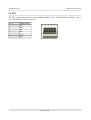
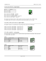
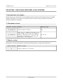
5.8 PWR jack
The power jack used is the typical 2.5mm one used by Olimex in most of our products. You should
provide 5 volts direct current and the required current may vary depending on the peripherals
connected to the board. The power supply you use should be capable of providing at least 1A of
current.
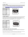
Pin #
Signal Name
1
Power Input
2
GND
More info about the power supply can be found in chapter 5 of this manual.
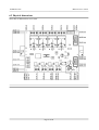
5.9 Additional hardware components
The components and circuits below are mounted on MOD-IO but are not discussed thoroughly in
the document above. They are listed here for completeness:
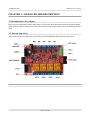
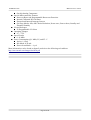
PWR_LED – shows whether the board is powered; turns on upon powering the board
STAT LED – general purpose LED, that can be programmed by the user; blinks upon powering the
board; connected via R11 (330 Ohm) to Atmega16l pin 43 ((AIN1)PB3).
Status LED (red) with name LED1 – visualize input (IN1) state.
Status LED (red) with name LED2 – visualize input (IN2) state.
Status LED (red) with name LED3 – visualize input (IN3) state.
Status LED (red) with name LED4 – visualize input (IN4) state.
Status LED (green) with name O1 – visualize relay (REL1) state.
Status LED (green) with name O2 – visualize relay (REL2) state.
Status LED (green) with name O3 – visualize relay (REL3) state.
Status LED (green) with name O4 – visualize relay (REL4) state.
RST button – used to reset the board connected to Atmega16A pin 4 (RESET).
BUT button – general purpose button, that can be programmed by the user; connected to
Atmega16A pin 11 ((INT0)PD2).
Quartz crystal Q1 – 8 MHz, connected to ATmega16A pin 7 (XTAL2) and pin 8 (XTAL1).
Quartz crystal Q2 – 32.768kHz (real-time clock) quartz crystal, connected to ATmega16A pin 25
((TOSC1)PC6) and pin 26 ((TOSC2)PC7).
Reset circuit – MOD-IO reset circuit includes a reset chip MCP130T (U2), AVRISP connector pin
5, JTAG connector pin 6, Atmega16A pin 4 (RESET), R9 (100R), R10 (10k), C10 (100nF) and a
RST button.
Page 24 of 30