Download Now

Transcript
StarFinder Lite
User’s Manual & Reference Guide
Revision 1.3 – 2013
©1999-2008 by Laipac Technology, Inc. All rights reserved – The Specifications and information regarding the products in this manual are subjected to change without
notice. All statements, information, and recommendations in this manual are believed to be accurate but are represented without warranty of any kind, express or implied,
users must take full responsibility for their applications of any Products - Reproduction of the contents of this manual, in whole or in part, without written permission of
Laipac Technology, Inc. is prohibited.
Laipac Technology Inc.
StarFinder Lite User’s Manual & Reference Guide
Federal Communications Commission (FCC) Statement
This equipment has been tested and found to comply with the limits for a Class B digital device,
pursuant to part 15 of the FCC rules. These limits are designed to provide reasonable protection
against harmful interference in a residential installation. This equipment generates, uses, and
can radiate radio frequency energy and, if not installed and used in accordance with the
instructions, may cause harmful interference to radio communications. However, there is no
guarantee that interference will not occur in a particular installation. If this equipment does
cause harmful interference to radio or television reception, which can be determined by turning
the equipment off and on, the user is encouraged to try to correct the interference by one or
more of the following measures:
-Reorient or relocate the receiving antenna.
-Increase the separation between the equipment and receiver.
-Consult the dealer or an experienced installer for help.
You are cautioned that changes or modifications not expressly approved by the party
responsible for compliance could void your authority to operate the equipment.
FCC RF Radiation Exposure Statement:
1. This Transmitter must not be co-located or operating in conjunction with any other antenna or
transmitter.
2. This equipment complies with FCC RF radiation exposure limits set forth for an uncontrolled
environment.
3. This equipment should be installed and operated with a minimum distance of 20 centimetres
between the radiator and your body.
CE Marking
This device has been tested to and conforms to the regulatory requirements of the European Union
and has attained CE Marking. The CE Mark is a conformity marking consisting of the letters
“CE”. The CE Mark applies to products regulated by certain European health, safety and
environmental protection legislation. The CE Mark is obligatory for productions it applies to: the
manufacture affixes the marking in order to be allowed to sell his product in the European market.
This product conforms to the essential requirements of the R&TTE directive 1999/5/EC in order to
attain CE Marking. A notified body has determined that this device has properly demonstrated that
the requirements of the directive have been met and has issued a favorable certificate of expert
opinion. As such the device will bear the notified body number 0560 after the CE mark.
The CE Marking is not a quality mark. Foremost, it refers to the safety rather than to the quality of
a product. Secondly, CE Marking is mandatory for the product it applies to, whereas most quality
markings are voluntary.
Marking: The product shall bear the CE mark, the notified body number(s) as depicted to the right.
CE0560.
© 2012-2021 by Laipac Technology Inc. All Rights Reserved.
Page 2
Laipac Technology Inc.
StarFinder Lite User’s Manual & Reference Guide
Additional regulatory conformance
Specific details about compliance to the following standards and regulatory bodies may be
obtained from Laipac Technology Inc.
• PCS Type Certification Review Board (PTCRB)
• Based on Cellular Telecommunications and Internet Association (CTIA) Over the Air (OTA)
•
performance tests
EN 301 511, EN 300 440, EN 62311, EN 301 489-1-3-7 and 60950-1 testing.
This device complies with Industry Canada license-exempt RSS standard(s). Operation is subject
to the following two conditions:
(1) this device may not cause interference, and
(2) this device must accept any interference, including interference that may cause undesired
operation of the device.
Le présent appareil est conforme aux CNR d'Industrie Canada applicables aux appareils radio
exempts de licence. L'exploitation est autorisée aux deux conditions suivantes :
(1) l'appareil ne doit pas produire de brouillage, et
(2) l'utilisateur de l'appareil doit accepter tout brouillage radioélectrique subi, même si le
brouillage est susceptible d'en compromettre le fonctionnement.
This Class【B】 digital apparatus complies with Canadian ICES-003.
© 2012-2021 by Laipac Technology Inc. All Rights Reserved.
Page 3
Laipac Technology Inc.
StarFinder Lite User’s Manual & Reference Guide
Table of Contents
1
INTRODUCTION
6
2
FEATURES
7
3
INITIAL SETUP
8
3.1
What you will need
8
3.2
Setup Summary
9
3.3
Installing the StarFinder Lite Software
10
3.3.1
Introduction to utility software
10
3.3.2
Installation of utility software
10
3.3.3
Installation of USB driver
10
3.4
Configuration of StarFinder Lite
11
3.4.1
Start configuration of your device
11
3.4.2
Basic Configuration
11
3.4.3
Save setting into or read setting from the device
16
3.4.4
Acquire setting from or save setting into a configuration file
17
4
ADVANCED CONFIGURATION AND FEATURES
19
4.1
Setup Settings
19
4.2
System Settings
19
4.3
Input / Output Settings
24
4.4
Application Settings
29
5
5.1
HARDWARE DETAILS & LAYOUT
Specifications
© 2012-2021 by Laipac Technology Inc. All Rights Reserved.
31
32
Page 4
Laipac Technology Inc.
StarFinder Lite User’s Manual & Reference Guide
5.1.1
GPS Engine Specs
32
5.1.2
GSM Modem Specs
32
5.1.3
GPS Antenna Specs
33
5.1.4
GSM Antenna Specs
33
5.2
Installation
34
5.2.1
Required Hardware
34
5.2.2
Installing your Starfinder Lite
34
5.2.3
Considerations
34
5.2.4
Other Options
34
5.2.5
Power Connector
35
5.2.6
Buttons Input/Output
35
5.2.7
Analog Input
36
5.2.8
Optically Isolated Inouts
36
5.2.9
Three Relay Outputs
37
6
OPERATION
38
6.1
LED Operation
38
6.2
Position Reporting by Event
38
6.3
Position Reporting by Request
39
6.4
Serial Port
39
6.5
Function and its configuration method ---------------------------------- 40
© 2012-2021 by Laipac Technology Inc. All Rights Reserved.
Page 5
Laipac Technology Inc.
1
StarFinder Lite User’s Manual & Reference Guide
INTRODUCTION
The Starfinder Lite is a robust platform designed for remote vehicle tracking and security. It
combines both GSM/SMS and GPRS (Global System for Mobile Communications/ Short
Messaging Service and General Packet Radio Service) communications with ultra-sensitive GPS
technology to provide a rugged yet precise and reliable tracking service. The Starfinder Lite can
be used to report positions or events in real-time, as well as log positions for local or remote
downloading. The Starfinder Lite comes standard with two optical inputs for connecting to alarm
systems or other sensors, one analog inputs, and three output relays for ignition disabling and
remote door unlocking. A backup battery is also included.
Each Starfinder Lite can be programmed with a unique device ID and can send data to any static
or dynamic IP address or SMS base station. Configuration of the unit can be done locally, via the
Starfinder Lite configuration utility in Windows™, or over the air via GPRS or SMS. We
currently offer our web-based tracking application www.LocationNow.com for tracking and fleet
management. For custom applications, we can provide our ADK kit with confidential protocol to
software developers for platform integration.
© 2012-2021 by Laipac Technology Inc. All Rights Reserved.
Page 6
Laipac Technology Inc.
2
StarFinder Lite User’s Manual & Reference Guide
FEATURES
•
Worldwide GSM/GPRS Quad band 850/900/1800/1900MHz
•
Multi-mode ready for SMS only, GPRS only or SMS + GPRS
•
High Sensitivity GPS Receiver of 20 Ch.
•
GPS Accuracy 3 – 5 m
•
Dimension 9.7 x 5.9 x 2.6 cm
•
Built in jacks for SPK and MIC
•
Panic button and Dial button ready
•
Supply voltage range: 9 to 36VDC
•
Internal Li-Ion backup battery able to provide approximately 10h life from a full charge
•
Low operating power consumption (less than 1W after battery is charged)
•
Both configuration utility and unit are able to have accessing control (option)*
•
Operation Temperature -30C to 65C°
•
USB Port for configuration
•
Compatible with Mobile Data Terminal
•
2 Optically Isolated digital inputs
•
3 Outputs with relays
•
1 Analog input available
•
Multiple Geo-Fence capability with in/out fence alert
•
Data logger capability built in with 2500 positions memory to record time stamp, speed,
location, and event state.
•
3 Axial motion G-Sensor to report impact, accident, crash or towing event.
•
Real time dynamic position report based on time interval or distance traveled
•
Mileage report and over-speed alert
•
Assistance and Emergency call numbers with fail over capability
•
Power-saving options available (option)*
•
WAAS / EGNOS (optional)*
•
3.7V, 900mAh internal backup battery
•
External panic button and call-in answer button
Note:
For features with (option), please check with Laipac Technology Inc to know about their detail.
© 2012-2021 by Laipac Technology Inc. All Rights Reserved.
Page 7
Laipac Technology Inc.
StarFinder Lite User’s Manual & Reference Guide
3 INITIAL SETUP
This section will help you setup and configure your Starfinder Lite GPS tracking device.
3.1
What you will need
To begin your evaluation, you will need the following:
•
Starfinder Lite
•
Power and I/O harness cables complete with Voice and Panic buttons
•
GSM patch antenna (3 meters cable length)
•
GPS magnet mount antenna (5 meters cable length)
•
GPRS data enabled SIM card with known APN settings (2G and TDMA compliant)*
•
Your Identity Leaflet provided in the Evaluation Kit*
•
9-36V DC power supply
•
USB A to USB Mini B cable
•
PC with Windows XP™ or later Microsoft Operating System
*GPRS operation assumed
© 2012-2021 by Laipac Technology Inc. All Rights Reserved.
Page 8
Laipac Technology Inc.
3.2
StarFinder Lite User’s Manual & Reference Guide
Setup Summary
The setup summary is an outline of what must be accomplished in order to operate the device.
Detailed descriptions of these steps will be listed in the next sections.
1. Find a computer with Microsoft Windows O.S. and IE 8 supported by Adobe Flash Player 9.0
or above
2. Install the latest version of utility software
3. Complete pre-installation of USB driver on computer
4. Power on Starfinder Lite with DC power supply (12V)
5. Connect the Starfinder Lite to the computer and reset the unit with reset button
6. Install USB driver on computer
7. Run utility and reset unit with reset button
8. If unit is not activated (locked), activate (unlock) it
9. If the existing firmware does not meet the request of utility, update firmware
10. Configure the unit and save the settings to unit
11. Disconnect Starfinder Lite with computer
12. Connect the GPS and GSM antennas
13. Insert the valid SIM card into the SIM Card Tray on the front of the unit
14. Press reset button to valid the configuration and make the device start working
© 2012-2021 by Laipac Technology Inc. All Rights Reserved.
Page 9
Laipac Technology Inc.
3.3
StarFinder Lite User’s Manual & Reference Guide
Installing the Starfinder Lite Software
3.3.1 Introduction to utility software
“LocationNow Suite” is a stand-alone utility software package for all of the major GPS tracking
products from Laipac Technology Inc.
User can use the web link below to download its latest version, such as “LocationNow Suite
20131009”.
http://www.laipac.com/sflite201update.htm
Mainly, “LocationNow Suite” is able to provide the two functions below
● Configuration
● Firmware Update
The computer, used for installing this utility, should be with
● Microsoft Windows 7 O.S. (recommended)
● IE8/9/10 browser only, which being supported by Adobe Flash Player V9.0 or up
For Adobe Flash Player V9.0 or up, user has to download it by using Windows IE and the link
below rather than downloading it through any other browser.
http://get.adobe.com/flashplayer
3.3.2 Installation of utility software
This software package is a compressed file with suffix “.7z” or “.zip”, such as,
“LocationNowSuite20131009.7z”
Decompress it to get the executable program “LocationNowSuite20131009.exe”
Run “LocationNowSuite20131009.exe”.
Follow “Setup Wizard” instruction, click “Next”, step by step, user can complete the installation of
this utility software.
3.3.3 Installation of USB driver
Depending on what kind of Microsoft Windows Operating System being used on user’s computer,
the installation of USB driver procedure is different. User could find all those detail in Quick
Start Manual version 2.4, section 2.
© 2012-2021 by Laipac Technology Inc. All Rights Reserved.
Page 10
Laipac Technology Inc.
StarFinder Lite User’s Manual & Reference Guide
3.4
Configuration of StarFinder Lite
3.4.1
Start configuration of your device
Refer to Quick Start Manual’s section 4, “How to start configuration of your unit”
3.4.2
Basic Configuration
To ensure user’s unit is able to access remote server, such as Laipac’s LocationNow service
platform, some basic setting items are requested and described in this section.
a. SETUP
Device Info
Fig. 3.4.2.a
Device ID:
Specific unit identifier that identifies your device for online tracking. You
can locate the Device ID on your Identity Leaflet or more accurately in your
user account on the website www.LocationNow.com.
Password:
Used to protect the StarFinder Lite from other people affecting its operation
with SMS commands. You can locate the Password on your Identity
Leaflet.
GSM Band:
This is for setting a frequency that your GSM provider network operates at.
The North American network bands are 850/1900 and the European network
bands are 900/1800. If user is not sure what frequency his carrier operates
at, please contact them for the correct setting.
© 2012-2021 by Laipac Technology Inc. All Rights Reserved.
Page 11
Laipac Technology Inc.
SIM PIN Number:
b. SETUP
StarFinder Lite User’s Manual & Reference Guide
If your SIM card is password protected, enable this option and input the PIN
code. The PIN code tells the Starfinder Lite to use the user defined PIN
code when communicating with GSM
Services
Fig. 3.4.2.b
Wireless Data Plan
This section governs the default GSM connection settings or what the unit
will connect to first.
GPRS:
If you are using LocationNow tracking services, this must be enabled.
GPRS mode tells the device it will be transmitting its information across the
internet.
SMS:
If you are tracking service based on Short Message System rather than
LocationNow, SMS mode should be enabled. It tells the device to transmit
its information to another SMS device.
Wireless Voice Plan This section initializes the voice option in the StarFinder Lite
Voice:
Originally, this setting is designed to tell unit if the existing SIM card is with
voice calling enabled. Currently, unit has enabled this setting actively. Of
course, if you are using SIM card without Voice Plan, no calling or voice
communication can be accomplished.
Incoming Call:
This setting determines whether or not the unit will automatically answer
incoming calls. As prerequisite, Voice must be enabled first.
© 2012-2021 by Laipac Technology Inc. All Rights Reserved.
Page 12
Laipac Technology Inc.
StarFinder Lite User’s Manual & Reference Guide
Fall Back Mode
This section is used to decide how the unit will react in the event there is no
GSM coverage.
GPRS -> SMS:
In the event of GPRS communication is lost, the unit will automatically
switch to SMS mode. While GPRS becomes reacquired, the unit will
automatically switch back to GPRS mode of operation.
Note:
1. If user is operating his device exclusively in SMS mode, he may skip this step.
2. In the event that GPRS fails and SMS ‘Fall Back Mode’ has been set, unit will immediately try
its SMS connectivity. If there is no SMS connectivity, the unit will keep switching between
SMS and GPRS until the unit synchronizes with one of these 2 modes. It is noted that GPRS
takes priority if both SMS and GPRS connection exist.
c. SETUP
Network
Fig. 3.4.2.c
Wireless Carrier
This section covers the information required by the unit to access your
carrier’s Access Point.
GPRS APN:
The Access Point Name is used by your SIM card to connect to the GPRS
network. The Access Point is the carrier’s server through which the traffic
becomes converted from GSM to GPRS Internet traffic. Check with your
SIM Card provider for this item.
The user name authorises your SIM card to access your carrier’s Access
Point. It could be blank in most of case.
User Name:
© 2012-2021 by Laipac Technology Inc. All Rights Reserved.
Page 13
Laipac Technology Inc.
StarFinder Lite User’s Manual & Reference Guide
Password:
The password authenticates your SIM card to access your carrier’s Access
Point. It could be blank in most of case.
Server
This section governs the destination end point for the GPRS traffic
Domain Name 1a:
This is the domain name of the remote server. For www.LocationNow.com,
it will be ‘laipgw1.com’.
Port 1a:
This is the Port used by the remote server with Domain Name 1a. For
www.LocationNow.com , it should be ‘1688’.
Note:
As a rule, if both Domain Name 1a and Static IP 1a are set, unit will try to communicate with
remote server through the domain name first, IP address second. If both Domain Name 1a and
Static IP 1a are inaccessible for any reason, then, unit will turn to try its back-up server,
Alternative Server, if it exists. Unit will try domain name of Alternative Server first, IP address
second.
It is suggested that user does not fill in Domain Name 1a and Domain Name 2a with Static IP
address.
Warning:
If unit has a ‘Fall Back Mode’ setting, along with Primary Server and Alternative Server, when it
loses its GPRS connectivity with its remote servers, both Primary and Alternative Server, unit will
initiate its action of ‘Fall Back Mode’. Refer to introduction to Fall Back Mode.
ALTERNATIVE SERVER
Configuration of the Alternative Server is optional.
Alternative Server is a backup server and used when the primary server is not unavailable. For its
configuration parameters, Domain Name 2a and Port 2a, as well as Static IP 2 and Port 2,
please refer to introduction to Server.
DNS SERVER
DNS IP 1 and 2: Allows you to specify DNS servers by using the IP address. Since unit’s internal
GSM module does this already, these settings are optional.
© 2012-2021 by Laipac Technology Inc. All Rights Reserved.
Page 14
Laipac Technology Inc.
d. System
StarFinder Lite User’s Manual & Reference Guide
Report
Fig. 3.4.2.d
Report and its setting:
This option allows you to specify how frequent the unit will send a position update. You can
specify the report by time value in hours, minutes, and seconds. Also, user can specify the report
by distance value in kilometres, miles, or yards.
© 2012-2021 by Laipac Technology Inc. All Rights Reserved.
Page 15
Laipac Technology Inc.
StarFinder Lite User’s Manual & Reference Guide
3.4.3 Save setting into or read setting from the device
Save setting into unit and valid it
Once user complete the configuration, he should click “Save All Setting to Device” button to save
the edited setting into unit if this saving process is OK, Operator should see the pop up window
with prompt “Writing new setting … Success”.
To valid this configuration, user needs
● Disconnect computer with unit
● Insert a valid SIM card into unit and power up the unit with DC power supply (12V)
● Reset unit with reset button to start running application
Read the setting from units
By clicking “Read Setting from Device” button, user can read the reside configuration from the
unit, which being connected to the running utility.
If unit has never been configured and valid its configuration, this reading configuration operation
will be failure.
© 2012-2021 by Laipac Technology Inc. All Rights Reserved.
Page 16
Laipac Technology Inc.
3.4.4
StarFinder Lite User’s Manual & Reference Guide
Acquire setting from or save setting into a configuration file
Acquire setting from a existing configuration file
User can acquire a set of configuration from a saved configuration file on his computer
a. Click “FILE”
“Import file”, see Fig. 3.4.4a and 3.4.4b
Fig. 3.4.4a
Fig. 3.4.4b
b. From the existing files to select a prefer one, such as, “SF-Lite configurati-1”, then click “Open”
If reading file is successful, user can see a pop-up window with prompt “Success”.
© 2012-2021 by Laipac Technology Inc. All Rights Reserved.
Page 17
Laipac Technology Inc.
StarFinder Lite User’s Manual & Reference Guide
Save the current configuration into a configuration file
User can save the current edited configuration into to a configuration file follow the steps below
c. Click “FILE”
“Save”, see Fig. 3.4.4c and Fig. 3.4.4d
Fig. 3.4.4c
Fig. 3.4.4d
d. User should type in the name of this new configuration file, such as, “configuration-2”,
then, click “Save”.
© 2012-2021 by Laipac Technology Inc. All Rights Reserved.
Page 18
Laipac Technology Inc.
StarFinder Lite User’s Manual & Reference Guide
4. Advanced Configuration and Features
This section introduces all other configuration settings not covered by section 3.4.2 Basic
Configuration. Those settings can be categorized into 4 major parts: SETUP, SYSTEM, I/O, and
APPLICATION. Among them, SYSTEM settings are concerned with reporting and voice setup.
I/O settings are used for customizable I/O functionality. The APPLICATION settings are used
for other types of event messages.
4.1 Setup Setting
Refer to section 3.4.2, a to c
4.2 System Setting
SYSTEM
Report
Report and its setting: This option allows you to specify how frequent the unit will send a position
update. You can specify the report by time value in hours, minutes, and
seconds. You can specify the report by distance value in kilometers, miles,
or yards.
Waypoints per Report: This is a user defined value used for report bursting and is governed by
report by time. An example is if the number of waypoints per report is set to
5 and the report by time interval is set to 1 minute, in 5 minutes, the
receiving server will receive 5 waypoints.
Smart Log Report: The smart log report option allows the unit to automatically log its position
and alert information into internal memory in the event there is no GPRS
connectivity. When the Starfinder Lite reconnects to GPRS, the saved
messages will be sent to remote server actively. Automatically, this
function has been always enabled by unit. User can skip this setting
© 2012-2021 by Laipac Technology Inc. All Rights Reserved.
Page 19
Laipac Technology Inc.
SYSTEM
StarFinder Lite User’s Manual & Reference Guide
Data Logger
Waypoint Log:
Waypoints & Events Log setting gives you the option to log or store
waypoint and alert messages in the unit’s internal memory.
By Time Interval:
Logs messages into internal memory based on the specified time interval.
By Distance Interval: Logs messages into internal memory based on the specified distance
interval.
Memory Full Alert: Data Logger Memory Full alert will cause the unit to send an alert when the
internal memory of the unit is full. This means that once the unit runs out of
memory, an alert will be sent to the GPRS server
© 2012-2021 by Laipac Technology Inc. All Rights Reserved.
Page 20
Laipac Technology Inc.
SYSTEM
StarFinder Lite User’s Manual & Reference Guide
Phone Number
Assistance Number: When user presses the Panic button on 10-pin I/O cable, the number
programmed into the “Assistance Number” field will be dialled.
Emergency No 1:
If this number is set up and unit will send SMS message to the SMS device
with this No. under conditions below
a. User presses the Panic button on 10-pin I/O cable, or
b. Unit is triggered by Towing Alert or Accident Alert
c. Emergency No. 1 sending function related to these alerts are enabled.
SMS Base Station:
The SMS Base Station Number is used when the Starfinder Lite is operating
under SMS mode. All of the waypoints and alert messages will be sent to
the SMS Base Station Number. This number also can belong to a cell
phone, an SMS modem, or any SMS device. Once this No. is set up, device
only accept the command sent by SMS device with this No.
Note:
To use the Assistance Number for doing phone call, user’s SIM card must be with valid
Voice Plan
© 2012-2021 by Laipac Technology Inc. All Rights Reserved.
Page 21
Laipac Technology Inc.
SYSTEM
StarFinder Lite User’s Manual & Reference Guide
Server Query
Server Query:
Used as a GSM keep alive and tests the connection status of the Starfinder
Lite. This setting must be enabled first.
Query Interval:
The time interval in which the Starfinder Lite tests the GPRS and TCP/IP
connection between the server and itself. If server does not respond to the
connection-checking message sent out by Starfinder Lite, the unit will enter
into re-develop connection process.
© 2012-2021 by Laipac Technology Inc. All Rights Reserved.
Page 22
Laipac Technology Inc.
SYSTEM
StarFinder Lite User’s Manual & Reference Guide
Data/Time
Time Zone:
Use this to select your time zone so that the device knows your local
time.
Daylight Savings Time:
Use this to enable the daylight savings time start and end dates.
DST Start Date:
This is a user defined value of when the user starts their daylight
savings time.
DST End Date:
This is a user defined value of when the user ends their daylight
savings time.
© 2012-2021 by Laipac Technology Inc. All Rights Reserved.
Page 23
Laipac Technology Inc.
StarFinder Lite User’s Manual & Reference Guide
4.3 Input/Output Settings
I/O
Input
Input setting items allows you to activate and select the functionality related to input. Input 1 has
options “Disable” and “Ignition”. Input 2 has options “Disable”, “Trigger”, and “Counter”.
Trigger setting:
This option allows you to send an alert when the alert signal condition is
met on an Input. An alert is generated when the voltage level goes from
either a High to a Low or from a Low to a High. This setting is user
defined.
Counter setting:
This option allows the user to implement input 2 as a counter. The counting
signal can be specified as either a Low to High (Low High) or a High to
Low (High Low) voltage level change. The maximum counting speed is
50 times per second, with minimum voltage change of last at least 10 ms.
Counter Start Value: This option allows the device to record how many times the alert gets
triggered and accumulates from the value you set it to.
Counter Alert Value: This option allows you to tell the Starfinder Lite to send an alert when the
counter value reaches a user defined value. If you set it to 90, it will send an
alert once the counter’s value reaches 90.
© 2012-2021 by Laipac Technology Inc. All Rights Reserved.
Page 24
Laipac Technology Inc.
StarFinder Lite User’s Manual & Reference Guide
Note:
Input 1 has been reserved for detecting the trigger signal corresponding to vehicle’s ignition on/off
status. Input 1 needs to be enabled if either “Accident alert” or “Towering alert” functions to be
available. The trigger signal exerted on Input 1 should meet the following requests
1. Before starting engine, its input voltage is Logic Low
2. After starting engine, it keeps input voltage is Logic High
3. When engine shuts down, its input voltage is back to Logic Low
For definition of Logic level as its correspondent electrical characteristics, refer to section 5.2.8
I/O
Output
Output setting items allow user to activate and select the functionality related to output. All three
outputs are driven by individual internal relays and are wired as “Normally Open”. For the
“electrical characteristics” of the relays please locate the “electrical characteristics” chart located
on page 43.
Controller:
The “Controller” option is used to enable the functionality of an output. Each of the
3 outputs is responsible for a different function. The table below outlines those functions, which
being with firmware V1.34 and up
© 2012-2021 by Laipac Technology Inc. All Rights Reserved.
Page 25
Laipac Technology Inc.
Output
StarFinder Lite User’s Manual & Reference Guide
3
Switch
Type
Timed
Relay Action
off on off
2
Fixed
off
1
Timed
Off on off
off on off
on or on
Action
times
1
“on”
time (s)
1
off
1
Stay as
“on”
“off”
time (s)
Stay as
“off”
Stay as
“off”
---
12
1
1
Command Type
Send switch Relay
“off” Command.
Send switch Relay
“on” or “off”
commands.
Send switch Relay
“off” command.
Note:
a. “on” or “off” command is sent by remote server to control the behavior of those internal relays.
For customer who wants to use his own server, he needs purchase the protocol from Laipac.
b. As typical vehicle application examples, with proper external relays, user may use Output3 to
control door-open, Output2 for ignition on/off control and Output1 for driving a horn.
c. Depending on actual application request, the output control may have different mode, user
should check SF-Lite Application Firmware Release Note to know about what kind of output
control mode is being used by the application firmware he selects.
I/O
Buttons
Panic Button:
Allows user to activate the functionality of the panic button by enabling it.
Once enabled, after pressing panic button, unit will initiate the actions below
sequentially
● Send a panic alert message through GPRS connection to the remote server
● Send a SMS message to the SMS device with Emergency No. 1
● Initiate a phone call by dialing Assistance Number
© 2012-2021 by Laipac Technology Inc. All Rights Reserved.
Page 26
Laipac Technology Inc.
Call Button:
StarFinder Lite User’s Manual & Reference Guide
Allows you to activate the functionality of the call button by enabling it.
Once enabled, it will allow the user to select
● Auto Answer the incoming call, or
● Press this button to pick up the phone call
Note:
For unit with application firmware V1.34 and up, automatically, both of these 2 buttons have
been enabled by unit. User can skip this setting
I/O
Analog In
Analog Input: It is designed to detect input voltage, which ranging between 0.00 and 3.30 volts.
The threshold of voltage value can be specified through a pull-down list. As default,
it is set as Disable
• Alert High – if input voltage value is higher than High Level setting, device will send out a alert
report to server to remind of server an Alert High event occurs
© 2012-2021 by Laipac Technology Inc. All Rights Reserved.
Page 27
Laipac Technology Inc.
StarFinder Lite User’s Manual & Reference Guide
• Alert Low – if input voltage value is lower than Low Level setting, device will send out a alert
report to server to remind of server an Alert Low event occurs
• Alert High/Low – if input voltage is either higher than High Level or lower than Low Level
setting, device will send out alert report to server
I/O
Com
RS232 COM PORT:
Reserved by Laipac and not opened to customer yet
© 2012-2021 by Laipac Technology Inc. All Rights Reserved.
Page 28
Laipac Technology Inc.
StarFinder Lite User’s Manual & Reference Guide
4.4 Application Settings
Application
Speed & Mileage
Over Speed Alert:
In order to use this function, it must be enabled first. The Over Speed Alert,
formerly known as over-speed, is designed to send an alert if the unit moves
faster then the specified speed limit value.
Speed Limit:
The speed limit is user defined and can be set in kilometers or miles per
hour. If the unit travels faster than this value, an Over Speed Alert will be
sent to the GPRS server.
Mileage Accumulator: This function must be enabled before it can be used.
Unit is able to
accumulate distance based on a user defined “Mileage Starting Value” and
the unit of distance during unit moves. Whenever moving distance is
increased by 1(km/mile), the incremented value will be added to the
Accumulator’s current mileage value.
Starting Value:
The Mileage Start Value is user defined and is recommended to match the
odometer reading in the equipped vehicle. From there you can specify the
unit of distance being kilometers or miles and the mileage value will
accumulate from there.
Mileage Alert:
This alert must be enabled before it can be used. This alert will be sent to
the remote server whenever another new Mileage Delta value is reached
during vehicle running. It is used to generate a warning for vehicle
maintenance warning or oil change, etc is coming due. For example, if
Mileage Start Value is 0 km and Mileage Delta Value is 5000km, unit will
generate Mileage Alerts when Mileage Accumulator has its reading at 5000 km.
© 2012-2021 by Laipac Technology Inc. All Rights Reserved.
Page 29
Laipac Technology Inc.
StarFinder Lite User’s Manual & Reference Guide
Mileage Delta Value: This value is a user defined distance value. It is designed to provide a
warning related to the next vehicle maintenance or oil change job is due.
The unit of distance must be the same as the ‘Mileage Starting Value’. The
default setting for this value is 1000 km
Application
Park & Accident
Towing Alert:
The Towing Alert must be enabled before it can be used. This feature
requests ‘Input 1’to be enabled as “ignition”. When vehicle with the unit
shuts down its engine, if unit experiences a movement that generates 2G or
greater force, the unit will send an alert to the remote server. This may be in
a situation where someone tows a vehicle without consent.
Trigger Value:
The G Sensor Trigger Value has a default value of 2Gs and should be kept
at a low recommended value to sense movement.
Accident Alert:
The accident alert requires enabling before it is used. It is designed to sense
a high impact hit and send an alert upon receiving it similar to that of a
vehicle collision. In order to have this alert working properly, ‘Input 1’ must
be enabled as “ignition”, also, user should provide requested “ignition
on/off” signal on Input 1. See section 4.3 I/O – Note.
Trigger Value:
The G Sensor Trigger Value has a default value of 5Gs and should be kept
as a recommended value to sense a vehicle collision as opposed to a pot hole
© 2012-2021 by Laipac Technology Inc. All Rights Reserved.
Page 30
Laipac Technology Inc.
5
StarFinder Lite User’s Manual & Reference Guide
HARDWARE DETAILS & INSTALLATION
The Starfinder Lite is enclosed in a robust metal case and can withstand intensive shock and
temperature environments. The features on the front of the unit include a SIM card tray, a USB
port, the reset button, speaker and microphone jacks, 2 female SMA connectors for the GPS and
GSM antennas, and three LEDs to show the status of reporting and connectivity as shown in the
below image.
The connections available on the back of the unit include two optically isolated inputs and three
Relay outputs in the main I/O section labeled as 12V, one analog input and the TTL I/O ports used
for the call answer button labeled as 3-5V, a wide power supply input range of 9-36V, and RS232
interface as shown in the below image. Note: Please refer to sections 5.1.5 through 5.1.9 for
detailed electrical specifications.
© 2012-2021 by Laipac Technology Inc. All Rights Reserved.
Page 31
Laipac Technology Inc.
5.1
StarFinder Lite User’s Manual & Reference Guide
Specification
5.1.1
5.1.2
GPS Engine Specifications
Value
Units
Channels
20
Channels
RF Frequency
1575.42
MHz
Position update rate
1
Hz
Active antenna bias voltage
3
V
Position accuracy
< 10
Meters
Velocity accuracy
0.1
m/s
Time accuracy
1
uS
Cold start acquisition time
42
Seconds
Warm start acquisition time
38
Seconds
Hot start acquisition time
1
Seconds
Maximum velocity tracked
515
m/s
Maximum altitude tracked
18,000
Meters
Jerk
20
m/s3
Tracking Sensitivity
-159
dBm
Navigation Sensitivity
-159
dBm
GSM Modem Specifications
•
Quad-band GSM/GPRS component (850/900/1800/1900 MHz)
•
Designed for M2M and automotive applications
•
Class 4 (2W @ 850 / 900 MHz)
•
Class 1 (1W @ 1800 / 1900 MHz)
•
R&TTE, GCF, FCC, PTCRB, IC
•
Embedded TCP/IP stack.
•
GPRS Class 10
© 2012-2021 by Laipac Technology Inc. All Rights Reserved.
Page 32
Laipac Technology Inc.
5.1.3
5.1.4
StarFinder Lite User’s Manual & Reference Guide
GPS Antenna Specifications
Frequency
1575.42 +/- 3 MHz
VSWR
2.0 Max
Bandwidth
10 MHz Min
Axial Ratio
3dB Typical
Impedance
50 Ohm
Peak Gain
4 dBic Min
Gain Coverage
≥ -4dBic at 90° ≤ 0 ≤ 90° (over 75% volume)
Polarization
RHCP
DC Voltage
3.3V
GSM Antenna Specifications
Bands
850/900/1800/1900 MHz
Frequency Range
824~960 MHz // 1710~1990 MHz
Impedance
50 Ohm
VSWR
<2.0
Gain
2dBi
Radiation
Omni
Polarization
Vertical
Wave
Half Wave Dipole
© 2012-2021 by Laipac Technology Inc. All Rights Reserved.
Page 33
Laipac Technology Inc.
5.2
StarFinder Lite User’s Manual & Reference Guide
Installation
The difficulty level of installing your Starfinder Lite depends on which features you would like to
use. Outlined here will be the basic installation requirements for real-time tracking. You can refer
to the Optically Isolated Inputs, Outputs with relays, and Analog Port sections for more advanced
hardware features which may require a more intricate installation.
5.2.1
Required Hardware
•
Starfinder Lite
•
Power, I/O harness, and call button cables
•
GSM patch antenna (3 meters long )
•
GPS magnet mount antenna ( 5 meters long )
•
GPRS enabled SIM card with known APN settings*
5.2.2
Installing your Starfinder Lite
To begin the installation, insert your activated SIM card into the SIM card tray. Connect the GSM
patch antenna (long and skinny) and GPS magnet antenna (square) to the appropriate connectors.
To power the unit, connect the power wiring harness and connect the red and black wires to a 936V DC supply. Make sure the supplied fuse is in place.
5.2.3
Considerations
There are a few considerations you should make when installing your Starfinder Lite. You should
make sure the unit is somewhat accessible so that you can connect the unit to a laptop via USB for
configuration and local NMEA-0183 output. The GSM antenna may be mounted almost anywhere,
as the GSM signal is generally very strong. The GPS antenna, however, should be mounted
somewhere with a clear line of sight to the sky under dash board, or at least in a position not
surrounded by metal. If you are having trouble receiving either signal, try relocating the antenna.
Another consideration is, if user wants to get high quality Audio performance, please keep distance
SF_Lite unit with electromagnetic noise source.
5.2.4
Other Options
The Starfinder Lite comes with many other options which may need installation. There are 2
optically isolated inputs, 3 Relay outputs, and 1 analog port which may need to be connected and
would rely on the specific application for installation details. A certified car audio/security
installer should be familiar with connecting the relays to door locks or starter triggers. The specs
and considerations for these other features can be found later in this section.
© 2012-2021 by Laipac Technology Inc. All Rights Reserved.
Page 34
Laipac Technology Inc.
5.2.5
StarFinder Lite User’s Manual & Reference Guide
Power Connector
The main Power supply voltage could work in the range of 9-36V. Typical power consumption of
the Starfinder Lite is 1W with peaks up to 5.5W. The current drawn is a result of power over
voltage, thus a low voltage power supply will need to provide more current.
5.2.6
Buttons Input/Output
These four connections are used by the StarFinder Lite Button/Analog cable set. If you are using
these without the standard cable set, the following summarizes the use of these connections.
Input BIO1 – Active LOW; will start, answer, or end a phone call (if enabled)
Input BIO2 – Active LOW; will send a Panic report to LocationNow (if enabled)
Output BIO3 – Normally LOW; indicates phone call status (used to drive LED)
GND – Common Ground
The inputs are standard 3.3V to signal a logical HIGH, and tolerant up to 5V; exceeding 5V can
damage your StarFinder Lite.
© 2012-2021 by Laipac Technology Inc. All Rights Reserved.
Page 35
Laipac Technology Inc.
5.2.7
StarFinder Lite User’s Manual & Reference Guide
Analog Input
Input voltage
Resolution
Sample Time
0-3.3V
10 bit
100ms
Analog Input – When enabled, the analog port is used to measure input voltage from 0-3.3V and
will send an alert when the voltage exceeds the level specified in your configuration. The Analog
input is tolerant up to 5V; exceeding 5V can damage your StarFinder Lite.
Analog GND – This is the ground reference for the Analog Input signal.
5.2.8
Optically Isolated Inputs
The positive wires are the sensing wires or wires that detect the voltage changes and the negative
wires are for common ground. The positive wires are most commonly connected to solenoid wires
that drive ignition, horn, air conditioning, gas cap, door open/closed status, etc.
When the inputs are enabled, they will send an alert when the specified condition is met, and all
have the same electrical characteristics and behavioural options.
© 2012-2021 by Laipac Technology Inc. All Rights Reserved.
Page 36
Laipac Technology Inc.
StarFinder Lite User’s Manual & Reference Guide
Electrical/Logic Levels Characteristics
Logical HIGH
Logical LOW
Minimum
Voltage Amperage
3.5V
1.3mA
0V
0mA
Maximum
Voltage Amperage
18V
6.7mA
1.5V
1.1mA
Note: An input level exceeding 19V could damage the StarFinder Lite and should be avoided.
5.2.9
Three Relay Outputs
The Starfinder Lite has three relay outputs which can be remotely controlled by the control center.
All three outputs have the same electrical characteristics and behavioral options. The outputs
serve as a switch either to drive an external relay or to open/close an existing low amperage
circuit. Follow the electrical characteristics chart below or damage may be incurred to both unit
and vehicle. Also review page 30 for the output behavior.
Electrical Characteristics
Maximum Allowable Voltage
AC 125 V
DC 60 V
DC 30 V
Maximum Allowable Current
0.5A
0.3A
1A
The switch status of internal Relay when its correspondent output is disabled
Relay 1 --- normally opened;
Relay 2 --- normally opened;
Relay 3 --- normally opened;
© 2012-2021 by Laipac Technology Inc. All Rights Reserved.
Page 37
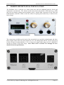
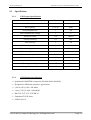
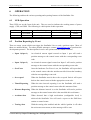
Laipac Technology Inc.
6
StarFinder Lite User’s Manual & Reference Guide
OPERATION
The following outlines the various operating and reporting features of the Starfinder Lite.
6.1
LED Operation
Three LEDs are on the front of the unit. They are used to indicate the working status of power
supply , GPS, and GSM. The following is a description of their operation.
LED
Power (Red)
Off
Slow Flashing
External power
not available
GPS (Green)
GSM (Yellow)
6.2
Fast Flashing
GPS Searching for Position
Searching for GSM network
Keeping On
External power
available
GPS fixed
GSM network connected
Position Reporting by Event
There are many events which can trigger the Starfinder-Lite to send a position report. Most of
them are outlined below. For other possible messages, contact [email protected] to purchase the
development protocol. The descriptions in italics are options and not standard features.
•
Input 1 (Opto 1)
An electrical current signal exerted on Input 1 port will send a
position message to the control center with the corresponding event
code.
•
Input 2 (Opto 2)
An electrical current signal exerted on Input 2 will send a position
message to the control center with the corresponding event code.
•
Geo-Fence
Once the hardware Geo-Fence is set, the Starfinder will report back
to the control center when the unit has travelled in/out the boundary
with the corresponding event code.
•
Over speed
When the Starfinder travels above the set speed limit it will report
back to the control center with the appropriate event code.
•
Timed Reporting
When the time interval reporting is set the Starfinder will send a
position message to the control center after this amount of time.
•
Distance Reporting When the distance interval is set the Starfinder will send a position
message to the control center after it has travelled this set distance.
•
Accident Alert
When detected that a high acceleration (configurable level) is
achieved the Starfinder Lite will send a report to the SMS base
station or control center.
•
Towing Alert
With the towing alert enabled and the vehicle ignition is off when
the unit senses movement, an alert message will be sent.
© 2012-2021 by Laipac Technology Inc. All Rights Reserved.
Page 38
Laipac Technology Inc.
•
DL Memory Full
StarFinder Lite User’s Manual & Reference Guide
Data Logger Memory Full alert will cause the unit to send an alert
when the internal memory of the unit is full or has reached max
capacity.
•
Mileage Alert
Mileage alert will cause the unit to send an alert when travel distance
reaches the value specified by user.
* When both time and distance intervals are set they work dynamically together like an ‘OR’
operation. This means that whenever either condition is met, it will report.
* For detail above refer to section 4.
6.3
Reporting by Request
In addition to automatically reporting the position you can manually request the current position or
settings. The following are some parameters which can be requested.
6.4
•
System information such as firmware version and memory size
•
Current position
•
Current mileage or speed limit setting
•
Current Report settings
•
Current Geo-Fence settings
•
Current log settings
•
Current input status
•
Current output status
Serial Port
It is reserved now. If user wants to have other external device to interface to this port, please check
with Laipac Technology Inc.
© 2012-2021 by Laipac Technology Inc. All Rights Reserved.
Page 39
Laipac Technology Inc.
6.5
StarFinder Lite User’s Manual & Reference Guide
Function and its configuration method
This table lists the different functions that the Starfinder Lite offers and outlines where they can be
configured in reference to the configuration utility, remotely using our protocol, or with our LBS
www.locationnow.com platform.
Feature
Location Now Remote Config
Utility
Device ID
Device Password
GSM Band
SIM Pin Number
Time Zone
No
No
No
No
No
Yes
Yes
No
No
No
Yes
Yes
Yes
Yes
Yes
GPRS Mode
SMS Mode
Voice
Incoming call
GPRS to SMS fall back
No
No
No
No
No
Yes
Yes
No
No
No
Yes
Yes
Enabled
Yes
Yes
APN
APN username
APN Password
Domain name 1a
Port 1a
Static IP 1
Port 1
Domain name 2a
Port 2a
Static IP 2
Port 2
DNS IP 1
DNS IP 2
No
No
No
No
No
No
No
No
No
No
No
No
Yes
Yes
No
Yes
Yes
No
No
No
No
No
Yes
Yes
Yes
Yes
Yes
Yes
Yes
Yes
Yes
Yes
Yes
Yes
Yes
Yes
Report by time
Report by distance
Smart Log
Air time green mode
Yes
Yes
No
No
Yes
Yes
No
No
Yes
Yes
Enabled
Yes
Waypoints & Events Log
Log by Time Interval
Log by Distance Interval
Data Logger Memory Full Alert
No
No
No
Yes
Yes
No
Yes
Yes
Yes
Assistance Number
Emergency Number 1
Emergency Number 2
Yes
Yes
Reserved
Yes
Yes
Reserved
Yes
Yes
Reserved
© 2012-2021 by Laipac Technology Inc. All Rights Reserved.
Page 40
Laipac Technology Inc.
StarFinder Lite User’s Manual & Reference Guide
SMS Base Station Number
Server Query Selection
Server Query Interval
No
No
No
Yes
No
Yes
Yes
Yes
Yes
Input 1 as
Alert when Ignition on-off
Counter 1 Starting Value
Alert when Counter 1 Reaches
Input 2 as
Alert when Door open-close
Counter 2 Starting Value
Alert when Counter 2 Reaches
No
No
No
No
No
No
No
No
No
No
No
No
No
No
No
No
Yes
Yes
Yes
Yes
Yes
Yes
Yes
Yes
Output 1 as
Starter Control on-off
Timer Control 1 Value
Output 2 as
Horn Control on-off
Timer Control 2 Value
Output 3 as
Siren Control on-off
Timer Control 3 Value
No
No
No
No
No
No
No
No
No
No
No
No
No
No
No
No
No
No
Yes
Yes
Yes
Yes
Yes
Yes
Yes
Yes
Yes
Panic Button
Panic Alert with Following Action
Call Button
Call Function – pick up the phone
Enabled
Enabled
Enabled
Enabled
Enabled
Enabled
Analog Input
Alert when Analog Input Reaches
No
No
No
No
Yes
Yes
RS232 COM Port
Interface With
Reserved
Reserved
Reserved
Reserved
Reserved
Reserved
Speed Limit Alert
Speed Limit
Mileage Accumulator
Mileage Starting Value
Mileage Alert for Maintenance
Mileage Delta Value
No
Yes
No
Yes
No
No
No
Yes
No
Yes
No
No
Yes
Yes
Yes
Yes
Yes
Yes
Towing Alert
Towing G-Sensor Trigger Value
Accident Alert
Accident G-Sensor Trigger Value
No
No
Yes
Yes
No
No
Yes
Yes
Yes
Yes
Yes
Yes
Geo-fence Setup
Switch Relay 1
Switch Relay 2
Yes
Yes
Yes
Yes
Yes
Yes
No
No
No
© 2012-2021 by Laipac Technology Inc. All Rights Reserved.
Page 41
Laipac Technology Inc.
Switch Relay 3
Request Real Time Position
Request Device Data
Request Current Status
Disable G-sensor
Disable Geo-fence
StarFinder Lite User’s Manual & Reference Guide
Yes
Yes
Yes
Yes
Yes
Yes
Yes
Yes
Yes
Yes
Yes
Yes
© 2012-2021 by Laipac Technology Inc. All Rights Reserved.
No
No
No
No
No
No
Page 42