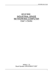
1
Asset-Link 4XX
User Manual
Installation and Operating Instructions
Revision:
1.1
Revision Date:
June 17, 2004
Document Number:
970-00047
Specifications subject to change without notice
Asset-Link 4XX User Manual
970-00047
May 10, 2004
Rev. 1.0
Record of Changes
Version
1.0
1.1
1.2
CSI Wireless©2004
Date
11/24/03
06/17/04
07/19/04
Title or Brief Description
Initial Release
Revised
No Audio
Specifications subject to change without notice
Entered By
C. Carver
L. Yu
L. Yu
Page ii
Asset-Link 4XX User Manual
970-00047
May 10, 2004
Rev. 1.0
Acronyms and Abbreviations
A
AMPS
BPS
CCA
Cellular
DAC
dB
DC
DPSK
EIA
ESD
FCP
FLASH
GPS
GPRS
GSM
I/O
LCP
mW
PDI
PPM
RF
rms
RSSI
RTC
SAT
SMB FAKRA
ST
TIA
V
CSI Wireless©2004
Amperes
Advanced Mobile Asset-Link System
Bits per Second
Circuit Card Assembly
A Asset-Link system based on cells of RF
Digital to Analog Converter
decibel
Direct Current
Differential Phase Shift Keying
Electronics Industry Association
Electrostatic Discharge
Function Control Processor
a non volatile memory type
Global Positioning System
General Packet Radio Service
Global System Mobile
Input or Output
Local Controller Port – serial I/O
milliwatt
Packet Data Interface
Parts per Million
Radio Frequency
Root Mean Squared or averaged
Received Signal Strength Indicator
Real Time Clock
Supervisory Audio Tone
RF Connector Based on FAKRA/USCAR Standards
Signaling Tone
Telecommunications Industry Association
Volts
Specifications subject to change without notice
Page iii
Asset-Link 4XX User Manual
970-00047
May 10, 2004
Rev. 1.0
Definitions
Action
Almanac
Asset Power
Baud
Battery Power
Ears-On
Ears-Off
Ephemeris
Exception
Fix
Page
Supply Power
Typical
2-D
3-D
CSI Wireless©2004
A programmed response to an exception.
A subset of orbital parameters from the GPS satellite ephemeris used to
calculate approximate satellite positions and velocities.
External power provided by the host vehicle or asset.
A unit of measurement specifying the signaling rate (Signals/Sec).
Power provided by either the optional external 12-V backup battery or
>7.0V internal battery.
A system sub-state in Active operating mode that enables the cellular
module (AMPS and MicroBurstTM Page).
A system sub-state in Active operating mode when cellular module is
switched off
A set of GPS satellite parameters used to calculate precise satellite
positions and velocities.
A predefined event or condition that causes a programmed response
(Action).
A location determination
The event of receiving a cellular telephone call via the AMPS Control
Channel.
Power provided to Asset-Link, regardless of source.
Expected value under normal operating conditions.
two dimensional
three dimensional
Specifications subject to change without notice
Page iv
Asset-Link 4XX User Manual
970-00047
May 10, 2004
Rev. 1.0
Table of Contents
1
INTRODUCTION.............................................................................................1-8
1.1 PURPOSE..........................................................................................................1-8
1.2 SCOPE ..............................................................................................................1-8
1.3 ASSET-LINK PRODUCT NUMBERING ................................................................1-8
1.4 REFERENCED DOCUMENTS ..............................................................................1-9
1.4.1 CSI-Wireless documents:...................................................................... 1-9
1.4.2 Public Documents or Standards ............................................................ 1-9
1.5 OPERATIONAL OVERVIEW .............................................................................1-10
1.6 SYSTEM PRODUCT FEATURES ........................................................................1-11
2
PRODUCT DESCRIPTION .............................................................................2-1
2.1 DETAILED SYSTEM DESCRIPTION ....................................................................2-1
2.2 MECHANICAL DIMENSIONS .............................................................................2-2
2.3 GPS RECEIVER ................................................................................................2-2
2.3.1 GPS Position/Velocity Fix .................................................................... 2-2
2.4 FUNCTION CONTROL PROCESSOR ....................................................................2-4
2.4.1 Non-Volatile Memory ........................................................................... 2-4
2.4.2 FCP Operating Modes........................................................................... 2-5
2.4.2.1 FCP Sleep Mode Operation.............................................................2-6
2.4.2.2 Active Mode ....................................................................................2-7
2.4.2.3 Full-Power Mode.............................................................................2-9
2.4.3 Power Off Mode.................................................................................. 2-10
2.4.4 Connection and Configuration ............................................................ 2-10
2.5 POWER MANAGEMENT ..................................................................................2-11
2.5.1 Power Input Protection........................................................................ 2-11
2.5.2 MicroBurst™, Control Channel Data ................................................. 2-11
3
APPLICATION I/O CONNECTOR SPECIFICATIONS ................................3-1
3.1 APPLICATION I/O CONNECTOR TYPE AND PINOUT ..........................................3-1
3.2 POWER INPUT SPECIFICATIONS ........................................................................3-2
3.2.1 Power Requirements ............................................................................. 3-2
3.2.2 Power Consumption Profile .................................................................. 3-2
3.2.3 Grounding “Precautions” ...................................................................... 3-2
3.2.4 Ground Wire Size.................................................................................. 3-3
3.2.5 Grounding Voltages .............................................................................. 3-3
3.2.6 Power Supply Over Voltage Protection ................................................ 3-3
3.2.7 Power Supply Reverse Voltage Protection ........................................... 3-3
3.2.8 Power Supply Decay to Zero Volts....................................................... 3-3
3.2.9 Power Supply Engine Start Disturbances ............................................. 3-4
3.2.10 Power Supply Connector ESD .............................................................. 3-4
3.2.11 Power Supply Connector Load Dump .................................................. 3-5
3.3 RELAY DRIVER SPECIFICATIONS .....................................................................3-6
3.4 ANALOG TO DIGITAL CONVERTER INPUTS ......................................................3-6
CSI Wireless©2004
Specifications subject to change without notice
Page v
Asset-Link 4XX User Manual
970-00047
May 10, 2004
Rev. 1.0
3.5 PIC SERIAL DATA OUTPUT ............................................................................. 3-6
3.6 PIC SERIAL DATA INPUT ................................................................................ 3-6
4
AMPS/GSM CONNECTOR SPECIFICATIONS............................................ 4-1
4.1.1
4.1.2
4.1.3
4.1.4
4.1.5
4.1.6
5
GPS CONNECTOR SPECIFICATIONS ......................................................... 5-1
5.1.1
5.1.2
5.1.3
5.1.4
5.1.5
5.1.6
6
AMPs/GSM Cellular Interface Specification ........................................4-1
Cellular Connector Shield......................................................................4-2
Cellular Center Pin Voltage Protection .................................................4-2
Cellular Center Pin Short To Ground or Open Protection.....................4-2
Cellular Center Pin Over Current Protection.........................................4-2
Cellular Center Pin ESD Protection ......................................................4-2
GPS Connector ......................................................................................5-1
GPS Connector Shield ...........................................................................5-1
GPS Connector Center Pin Voltage Protection .....................................5-1
GPS Connector Center Pin Short To Ground or Open Protection.........5-1
GPS Connector Center Pin Over Current Protection.............................5-2
GPS Connector Center Pin ESD Protection ..........................................5-2
ANTENNAS ..................................................................................................... 6-1
6.1 CELLULAR AND GSM ANTENNA ..................................................................... 6-1
6.2 GPS ANTENNA ............................................................................................... 6-2
7
ENVIRONMENTAL SPECIFICATIONS ...........................................................3
7.1 ENVIRONMENTAL SPECIFICATIONS .....................................................................3
7.2 VIBRATION AND DROP TEST REQUIREMENTS .....................................................4
7.2.1 Vibration ................................................................................................... 4
7.2.2 Drop Test .................................................................................................. 4
7.3 EMC REQUIREMENTS .........................................................................................5
7.3.1 Regulatory EMC Requirements................................................................ 5
7.3.2 EMC with vehicle broadcast receivers ..................................................... 6
8
INSTALLING ASSET-LINK IN A VEHICLE ...................................................7
8.1 ANTENNA POSITIONING ......................................................................................7
8.2 MOUNTING LOCATION ........................................................................................9
8.3 I/O CONNECTION AND HARNESS DESIGN..........................................................10
CSI Wireless©2004
Specifications subject to change without notice
Page vi
Asset-Link 4XX User Manual
970-00047
May 10, 2004
Rev. 1.0
List of Figures
Figure 1 Typical Asset-Link Unit Deployment...................................................... 1-10
Figure 2 Asset-Link Functional Block Diagram ..................................................... 2-1
Figure 3 - Operating Mode Transitions .................................................................... 2-9
Figure 6 Vehicle Battery Voltage Drops During Engine Start................................. 3-4
Figure 7 Load Dump Pulse Test............................................................................... 3-5
Figure 8 Vibration Specifications.................................................................................4
List of Tables
Table 2-1 GPS Receiver Characteristics .................................................................. 2-2
Table 2-2 Establishment of Position Fix .................................................................. 2-3
Table 4-1 DB-25 Application I/O Connector Pin-Out ............................................. 3-2
Table 4-2 Asset Power - Absolute Maximum Ratings............................................. 3-2
Table 4-3 Asset Power Characteristics..................................................................... 3-2
Table 4-4 Power Consumption................................................................................. 3-2
Table 4-5 Load Dump Pulse Characteristics ............................................................ 3-5
Table 4-12 Microphone Input Characteristics..................................not included
Table 4-13 Earpiece Output Characteristics...........................................not included
Table 6-1 Cellular Interface Characteristics............................................................. 4-1
Table 7-1 GPS Connector Characteristics................................................................ 5-1
Table 8-1 GSM & Cellular Antenna ........................................................................ 6-1
Table 8-2 GPS Antenna............................................................................................ 6-2
Table 10-1 Environmental Specifications ....................................................................3
Table 10-2 Temperature Specifications .......................................................................3
CSI Wireless©2004
Specifications subject to change without notice
Page vii
Asset-Link 4XX User Manual
970-00047
May 10, 2004
Rev. 1.0
1 Introduction
1.1
Purpose
This document describes the basic user guide for the operation of the ASSET-LINK™ family of
products.
1.2
Scope
This manual describes the relevant hardware and firmware features in the necessary detail for
Telematics system developers. The primary interface with the product firmware is based on a
proprietary CSI Wireless communications interface called PDI (Packet Data Interface). The
Asset-Link allows communication on GSM and Cellular networks for maximum coverage in the
Americas. The product includes Aeris MicroBurstTM to allow small packet information transfer
over the Cellular Networks. The Asset-Link also has an integral GPS receiver that allows
position-sensing information to be available both locally, over packet networks, by SMS and by
the public switched wireless networks.
Detailed information on communications with the Asset-Link using PDI (Packet Data Interface)
or Application Development for the Asset-Link requires the use of AVL 2004 User Manual (97000050).
1.3
Asset-Link Product Numbering
The Asset-Link product numbering is composed of a 4 digit number followed by a 2 digit
firmware/ accessory suffix (4XYZ-AB). The first digit is always 4 for GSM products, the next
five digits decode as follows:
Digit 2
Digit 3
Digit 4
Frequency Bands (Cellular/DCS/PCS/etc.), “0” used for AMPS only.
Data or Modulation Type (MicroBurst, GPRS, etc.), “0” if none.
GSM data capability – “0” if not GPRS capable
Digit 5
Digit 6
FCP firmware level
Accessories included
CSI Wireless©2004
Specifications subject to change without notice
Page 1-8
Asset-Link 4XX User Manual
970-00047
1.4
May 10, 2004
Rev. 1.0
Referenced Documents
1.4.1 CSI-Wireless documents:
970-00050
AVL 2004 User Manual (Asset-Link 4XX Series)
910-00044
PDI Interface Manual, Asset-Link and AssetVision
1.4.2 Public Documents or Standards
GPS ICD-200C-004
NAVSTAR GPS Navigation User Interface Definition (12 April 2000)
TIA/EIA/IS-91
Mobile Station – Base Station Compatibility Standard for 800 MHz
Analog Cellular. October 1994.
TIA/EIA-690
Recommended Minimum Standards for 800 MHz Cellular Subscriber
Units, November 1, 2000
EIA/TIA-553
Mobile Station – Land Station Compatibility Specification. September
1989.
CSI Wireless©2004
Specifications subject to change without notice
Page 1-9
Asset-Link 4XX User Manual
970-00047
1.5
May 10, 2004
Rev. 1.0
Operational Overview
The Asset-Link series of products, extends the product family from CSI Wireless with addition of
GSM to the original Asset-Link 200 product. The Asset-Link provides a comprehensive range of
features for vehicle management, remote diagnostics, control and positioning at an affordable
price. The Asset-Link integrates GSM and Cellular (AMPS) data communications, global
positioning (GPS) and an intelligent power management system to permit asset tracking, event
monitoring, action scheduling, and vehicle parameter control. The product uses a proprietary
parameter driven configurable architecture to permit optimization for individual applications.
Figure illustrates a typical Asset-Link ™ unit deployment.
Figure 1 Typical Asset-Link Unit Deployment
CSI Wireless©2004
Specifications subject to change without notice
Page 1-10
Asset-Link 4XX User Manual
970-00047
1.6
May 10, 2004
Rev. 1.0
System Product Features
The Asset-Link product has the following major features
• Power management system for controlling power consumption on wide variety of vehicles
and equipment with 12 volt or 24 volt electrical systems.
• GPS position determination, with more than 60 days of position storage in memory.
• Integrated AMPS Class 3 Cellular Radio.
• AMPS control channel MicroBurst™ data ability
• AMPS or GSM circuit switched data
• GSM 2 watt (EGSM/GSM850) – 1watt (GSM1800/PCS1900) module
• GSM SMS messaging using Text
• Class 10 GPRS packet data capability with embedded TCP/IP capability
• Configurable application with 50 Geo–fences, 64 exceptions, 64 meters of 4 varieties
(interval, event, odometer and elapsed), 64 action groups (with up to 8 actions each) and
40 configurable schedules (with 21 discrete times or 7 periodic schedules each with local
or GMT time settings)
• 16 I/O ports (2 relay drivers, 8 GPIOs and 4 analog inputs, plus 2 serial ports).
• Eight digital bi-directional ports, 3 of 8 with wake-up capability
• Four 10 bit analog inputs for measuring temperature and other sensor inputs
• Two serial communications ports – one of these ports can be ordered as a dedicated
RS232 port for data communications needs, USB available soon.
• Two relay drivers that sink up to power to ground for conventional automotive relays
• I2C or SPI ports are available (shared with digital ports 4, 7 & 8)
• Real-time clock for scheduling and power management.
CSI Wireless©2004
Specifications subject to change without notice
Page 1-11
Asset-Link 4XX User Manual
970-00047
May 10, 2004
Rev. 1.0
2 Product Description
nvSRAM
Flash
RS232
Txvr
GPS Rx
FCP (ARM7)
Serial
Tx/Rx
D
B
2
5
Audio
5V reference
CAN Bus
4 ADC
8 GPIO (SPI)
1 UART
2 Relay Drivers
Asset Pwr
PIC I/O
uController
GSM Radio
Modem
D
B
9
8-36V
Power Supply
AMPS Radio
Figure 2 Asset-Link Functional Block Diagram
2.1
Detailed System Description
The following sections provide a description of the various system components.
Figure 2 on the preceding page is a block diagram of the Asset-Link system depicting
the major system components and interfaces.
CSI Wireless©2004
Specifications subject to change without notice
Page 2-1
Asset-Link 4XX User Manual
970-00047
2.2
May 10, 2004
Rev. 1.0
Mechanical Dimensions
The Asset-Link enclosure for the product will be approximately 5.8” x 3.4” x .9” to
the outside of the connectors.
2.3
GPS Receiver
The Asset-Link incorporates a low power integrated twelve-channel GPS receiver.
The GPS receiver is designed by CSI-Wireless utilizing the SiRFstarII LP GPS
architecture, which includes acquisition accelerator and multi path mitigation
hardware. The GPS receiver complies with ICD-GPS-200C.
The Asset-Link Global Positioning System (GPS) receiver shares the ARM7
processor with the FCP to determine position and provide control functions. The time
to position determination and the accuracy of position determination are dependant
upon the GPS LNA antenna performance as well as the GPS Antenna.
The frequencies used for the GPS receiver are centered on 1574 MHz, which are
referred to as L1. Other GPS frequencies are not supported by the Asset-Link . The
Asset-Link does not support WAAS.
Parameter
GPS Receive Frequencies
Tracking capabilities
Solution Update Rate
Satellite Reacquisition
“Snap” Start time
“Warm” Start time
“Cold” Start time
Signal Level
Maximum position speed
Position accuracy SA off
Position accuracy SA on
Velocity determination
Min
1569
4
-45
8
26
40
-155
0
----
Nominal
1574
7
-80
8
35
45
-141
-10
100
1
Max
1579
12
1
100
20
38
120
-108
999
14
120
--
Units
MHz
Satellites
seconds
milliseconds
Seconds
Seconds
Seconds
DBm
knots
meters 2D rms
meters 2D rms
meter/sec
Table 2-1 GPS Receiver Characteristics
2.3.1 GPS Position/Velocity Fix
The GPS receiver establishes a position fix with a 95% certainty as shown in Table
2-2. The following data provided by SiRF assumes a full view of the sky (360°
azimuth), actual field data will vary with antenna installation.
If the satellites are not equally distributed around the horizon as often happens in
urban canyons, and in covert vehicle installations, the fix circular error is more like a
large oval. The result is a large “DOP” (dilution of precision) and a lower fix
accuracy, as well as an increased time to first fix. Increased DOP (HDOP –horizontal
CSI Wireless©2004
Specifications subject to change without notice
Page 2-2
Asset-Link 4XX User Manual
970-00047
May 10, 2004
Rev. 1.0
error, VDOP – vertical error and TDOP – time error) affects fix accuracy but not fix
update rate, only time to first fix (TTFF).
Cold Start
TTFF
< 45 seconds (avg.)
Warm Start
< 38 seconds (avg.)
Hot Start
< 8 seconds (avg.)
SiRF Definition
A condition in which the GPS can arrive at a navigation
solution without initial position, time, current
ephemeris, and almanac data.
Start mode of the GPS receiver when current position,
clock offset and approximate GPS time are input by the
user. Almanac is retained, but ephemeris data is
cleared.
Start mode of the GPS receiver when current position,
clock offset, approximate GPS time and current
ephemeris data are all available.
Table 2-2 Establishment of Position Fix
Upon initial startup the GPS almanac data is downloaded from the GPS satellites and
requires 12.5 minutes to download completely. The almanac is updated weekly and is
typically valid for up to a month. On subsequent startups the almanac data does not
have to be reloaded provided it is still valid. To achieve a hot start the receiver must
have current satellite ephemeris data (each satellite transmits its own orbital
parameters). The satellite ephemeris data is transmitted every 30 seconds, changes
every hour, and is valid for up to 4 hours. In Asset-Link the satellite elevation
threshold is set to 7.5 degrees above horizon, this cannot be changed by
configuration.
Stored GPS position information will be updated when the Asset-Link GPS is
powered ON and receiving enough satellite information to calculate position and
velocity information (nominally 4 satellites). An internal filter screens out low PDOP
(position dilution of precision) fixes. The GPS receiver is powered on in the Full
Power mode and can be independently powered on or off in the Active mode. A GPS
“warm up delay” uses a configurable timer to delay certain actions requiring a GPS
fix, such as a cellular “check-in”, until the GPS has an opportunity to get a fix
(nominally set to 45 seconds). When GPS receiver is on, it acquires GPS fix once a
second.
GPS information can be requested through PDI commands, information such as:
• Date/Time the request for position information was processed.
• GPS position (latitude, longitude, and altitude).
• GPS time of week and week number indicating when this fix information was
calculated (time of fix).
• GPS 3-D velocity vectors (east, north, and up velocity vectors) or plane speed
and direction.
• Fix type, providing status of the fix (available/not available,number of satellite
vehicles used for fix, etc).
CSI Wireless©2004
Specifications subject to change without notice
Page 2-3
Asset-Link 4XX User Manual
970-00047
•
•
May 10, 2004
Rev. 1.0
GPS receiver status (antenna feed line fault, not detected, number of satellite
vehicles tracking)
GPS tracking for each satellite vehicle (azimuth, elevation, average
carrier/noise, ephemeris available, code locked, carrier pull-in, acquisition
failed, bit synchronization, sub-frame synchronization).
In both the Active and Full-Power mode, the GPS position is continuously logged to
non-volatile memory along with other Asset-Link status parameters. This information
is logged every second to nvSRAM, and saved to Flash when the system is powered
down. Please refer to section Error! Reference source not found. for GPS
configurable parameters
2.4
Function Control Processor
The FCP module in the ARM processor of the GPS receiver is the central intelligence
of the Asset-Link unit. The FCP module manages the cellular and GSM module
connection and controls the application. The application is controlled by the
navigation solution and performs exception handling (such as input signal and Geofence exceptions) based on schedules and actions.
2.4.1 Non-Volatile Memory
Cellular Module SRAM
16 Kbit
Cellular Module FLASH
512 Kbit
FCP nvSRAM
512 Kbit
FCP FLASH
32 Mbit
The FCP code consumes less than 20% of the available code space and allows
sufficient room for the complete download of new image in the case of an OTAP.
About 256K of space is reserved for constrain regions and geopolitical boundaries.
The balance of the flash memory (about 16M) is used for message and record storage.
The Asset-Link FCP uses two types of non-volatile memory storage: parallel
nvSRAM memory, and FLASH memory.
Memory Type
ARM nvSRAM
ARM FLASH
Life Expectancy
Infinite Write Cycles to SRAM
1M Store Cycles to nonvolatile elements
1M Erase & Program Cycles
The Cellular and GSM transceivers have separate Serial SRAM memory, and FLASH
memory.
Memory Type
Serial SRAM
FLASH
CSI Wireless©2004
Life Expectancy
1M Write Cycles
10k Cycles
Specifications subject to change without notice
Page 2-4
Asset-Link 4XX User Manual
970-00047
May 10, 2004
Rev. 1.0
2.4.2 FCP Operating Modes
The following description of the four operating modes and power management is a
very general description of the Asset-Link programming. Application providers can
and should develop their own specific configuration to maximize connectivity and
minimize battery consumption. Developers can use meters, voltage thresholds, I/Os,
actions, exceptions and schedules to create unique applications by the PDI commands
available through the AVL 2004 program. There are four major states for the FCP:
1. No Power
2. Sleep
3. Active
4. Full Power
Each may be invoked in response to exceptions that are logically combined with
either I/O inputs and/or voltage level of power resources. To create such a
configuration, the reader should refer to the AVL 2004 User Manual (970-00050).
Each of these states has specific power consumption and abilities, which are detailed
in the later sections of this manual.
Figure 3 shows the various power modes and operational states. Switching between
modes (or states) can be determined by singular, or combination events. (It must be
noted that some of these events can act in concert, in an additive manner, while others
are normally set to act alone, and still others are dominant over another). The I/O
controller monitors a majority of the bus activity (including serial and analog inputs)
using an I/O timer. The I/O timer is set following the detection of an activity at the
I/O ports. The I/O timer can also be set by a configurable action group. Both of these
monitoring events maximizes the potential for the FCP to remain in the sleep mode
and thus conserve power. The following are routinely monitored by the FCP:
• Activity on I/O controller or the FCP serial port
• Changing of the voltage of the power supply as measured at the main input of
the device, to a configurable threshold
• Expiration of the GPS warm-up timer, GPS fix Duration timer and Ears-On
timer. Ears-On timer is set when the cellular module is turned ON by a
configurable action group of an exception. The GPS timers are configurable
GPS parameters and are set when turning ON GPS receiver.
• Schedule keeping
• Active Elapsed timers that run over the threshold
• Exceptions that call Full-Power action
The following parameters relating to mode transition are configurable in the
hardware. AVL-2004 (see AVL 2004 User Manual 970-00050), the configuration
development tool, provides the usable value for each setting:
V SUPPLY Hi to Lo and Lo to Hi threshold
CSI Wireless©2004
Configurable 0 to 26 Volts
Specifications subject to change without notice
Page 2-5
Asset-Link 4XX User Manual
970-00047
May 10, 2004
Rev. 1.0
VAnalog1-4 Hi to Lo and Lo to Hi threshold
Configurable 0 to 26 Volts
I/O timer
Configurable between 2 s to 65535 s
Ears-On Timer
Configurable between 2 s to 65535 s
GPS warm-up timer
Configurable between 0 to 255s
GPS fix duration timer
Configurable between 0 to 65535s
I/O inputs poll rate (Power off mode)
Configurable 2 to 63 s
Note: nominal supply voltage range should be 8-36V DC.
2.4.2.1 FCP Sleep Mode Operation
In the Sleep Mode, the only section doing any processing is the Real Time Clock
(RTC). The processor periodically enters the “Activity Check” state from the Sleep
Mode. The interval for entry to the Activity Check state is configurable from 2 to 63
seconds and it is recommended 10-30s is used. In this mode the total power
consumption is nominally about 35uA.
In addition to the RTC, the I/O controller hardware is able to detect changes
(interrupts) on the serial port on the 25 pin connector (pin 9), three of the eight digital
GPIOs (GPIO 1, 2 & 3 – pins 2,15 & 3, respectively) and on the supply. The AssetLink can be made to enter “Activity Check” sub-mode with activity on these lines.
When doing the Activity Check, the four analog inputs, the power supply voltage;
and the Schedules and Elapsed timers are also checked. If any of these activities have
events that require processing, the Asset-Link will transition to Active mode.
When the Asset-Link enters Active mode, the two GPS timers, the ears-on timer and
the I/O timer are set, according to the configuration and the trigger, and begin to
count down to the time when Sleep mode will be entered.
Under most configurations when using SMS for data communications, it is advisable
that the device be configured to issue a status message before entry into the PowerOff mode. The status message will alert the host that the client device has entered the
Power-Off mode and thus can no longer respond. Many applications do the same for
entry into the Sleep mode, this alerts the service provider that the device can no
longer receive messages. In a usual vehicle application, the device shall remain in the
Sleep mode until awakened by either detecting the vehicle’s switched ignition circuit
turned on via one of the analog input, or upon sensing appropriate “wake-up” activity
on one of the three ‘wake’ digital GPIOs.
The following functions are disabled while the FCP is in the Sleep mode:
•
GPS Receiver
•
Cellular and GSM module
•
Data Log and Batch Processor
•
Timer (except elapsed timer) and Exception Handler
•
Action Processor
CSI Wireless©2004
Specifications subject to change without notice
Page 2-6
Asset-Link 4XX User Manual
970-00047
May 10, 2004
Rev. 1.0
Note: GPS receiver can be set to always ON when in Active mode. In this case the
two GPS timer will not take effect in the transition from Active mode to Sleep mode,
i.e., once the Ears-On timer and I/O timer expire, Asset-Link will transition to Sleep
mode.
2.4.2.2 Active Mode
Active Mode, a mode in which digital and analog inputs are monitored continuously;
additionally, one of the radio modules and GPS receiver are on or off (Ears-On and
Ears-Off, GPS On and GPS Off) at times according to actions configured. Note: only
one radio (AMPS or GSM) can be “Ears-On” at a time).
Upon entering this mode from Sleep, the GPS receiver will be turned on and the two
GPS timers – (1) warm-up timer and (2) “max fix” timer, are set according to GPS
parameters configuration.
When entering the Active mode from sleep, based on different triggering activities,
the I/O timer and Ears-On timer are set to count down with different values:
•
Triggered by digital input: I/O = 30s
•
Triggered by analog input: I/O = 300s
•
Triggered by serial port: Ears-On=300s, I/O=300s
•
Triggered by schedule or Elapsed timer: I/O = 60s + Sleep wake-up interval
•
Triggered by power supply: Ears-On = 300s, I/O =300s
An action can be invoked by an exception during the Active mode to reset the I/O
timer to any value up to 65535 seconds in order to prolong the mode.
If the either LCP port is active, the timer will continuously be set to 5 seconds in
order to let the LCP communication complete.
The Cellular or GSM Ears-On timer can also be set to any value up to 65535 seconds
through an action or a schedule. Once the Ears-On timer expires, the appropriate
radio module will be switched off and the Asset-Link will again return to the “EarsOff” sub-mode.
The capability to turn the GPS receiver ON/OFF is also configurable. If the GPS
power control capability is disabled (GPS receiver not allowed to power OFF), then
the GPS receiver is always ON when Asset-Link is in the Active mode. If the max fix
interval capability is enabled, then the GPS receiver is turned ON for a period of time
defined by “warm-up delay timer” and “GPS fix max duration timer” when entering
Active mode. Depending on the settings, when both the two timers countdown to zero
or a GPS fix is obtained, GPS receiver will be shut off. The GPS receiver can also be
shut off any time by an action.
If all the timers -- the two GPS timers, Ears-On and I/O timers, expire in Active
mode, the Asset-Link will transition to Sleep mode. If the GPS receiver is set to be
always ON in Active mode, then only the Ears-On and I/O timers expiration will lead
Asset-Link to transition back to the Sleep mode.
CSI Wireless©2004
Specifications subject to change without notice
Page 2-7
Asset-Link 4XX User Manual
970-00047
May 10, 2004
Rev. 1.0
The Active Mode allows the Asset-Link to operate at different power levels based on
configurations that are programmed for specific operating requirements. In most
configurations, the Asset-Link will enter this mode from “Full-Power” immediately
upon detecting the vehicle’s switched ignition circuit going to OFF (normally applied
to one of the digital inputs). In most cases the Asset-Link is configured to prevent the
device from remaining ON for a protracted period of time and depleting the asset
power (battery) after the ignition is turned OFF. This can be achieved by a proper
configuration of timers, VSUPPLY threshold, action groups etc. If vehicle battery
voltage is used for mode transition, be aware that the voltage can drop below 11.0v
during vehicle start. The voltage will normally rise above 13.8v immediately after
engine starts. Voltage transients of ±3.5v are not unusual on diesel engines during
engine start.
In some applications, issuing an alerting message to the application when entering
Active mode from “Sleep” is recommended so that the host is notified that the client
device is able to receive messages.
While in the Active mode, the device shall continue to support all routines and
activities supported in the Full Power mode:
• GPS (fix updates, constraint regions, constraint groups)
• Cellular and GSM modules (listening for any pages, packet data, calls or SMS
messages from the host when Ears-On)
• Check power supply voltage
• Check digital, analog and LCP inputs.
• Data Log and Batch Processor
• Timer, Event Monitor and Exception Handler
• Action Scheduler
• Action Processor
CSI Wireless©2004
Specifications subject to change without notice
Page 2-8
Asset-Link 4XX User Manual
970-00047
May 10, 2004
Rev. 1.0
Sleep
2-63sec timeout OR
Activity on LCP Port OR
Activity on any of 3 Interruptible GPIOs
OR
Power Interruption
Activity
Check
Sleep
No Activity
Activity on LCP Port OR
Activity on any of 3 Interruptible GPIOs
OR
Power Interruption OR
VANALOG1,2,3 or 4 >/< Threshold1,2,3 or 4 OR
Active Schedule OR
Active Over-threshold OR
Elapsed Timer
Ears_ON Timer Off AND
I/O Timer Off AND
GPS Warm-up Timer Off
AND
GPS Fix Duration Timer Off
Active
Ears_ON Timer
ON
Ears_Off
Ears_On
LCP Active OR
set I/O
Timer=20sec.
Ears_ON Timer
Off
GPS Timer
ON
GPS_Off
GPS_On
GPS Timer
Off
Full_Powe
r
Flag True
Full_Powe
r
Flag False
Full
Power
Figure 3 - Operating Mode Transitions
The above figure shows the relationship of the three primary operational modes and
how Asset-Link transitions from one mode to another.
2.4.2.3 Full-Power Mode
This is the full operational mode for the FCP. In this mode either the AMPS Cellular
Radio or the GSM module and the GPS receiver are powered on continuously. The
Asset-Link continuously monitors analog and digital I/O inputs, the power supply
voltage levels, and exceptions that have been enabled. The Asset-Link continuously
receives GPS position fixes and the AMPS Cellular Radio or GSM module is in a
standby mode waiting for a page.
If the communication via the AMPS Cellular Radio or GSM module is necessary, the
FCP will communicate the appropriate information via the appropriate radio.
When in Active mode, “Full-Power enabled” action can cause Asset-Link transition
to the Full-Power mode. While in Full-Power mode the device shall support all
routines and activities, as follows:
CSI Wireless©2004
Specifications subject to change without notice
Page 2-9
Asset-Link 4XX User Manual
970-00047
•
•
•
•
•
•
•
•
May 10, 2004
Rev. 1.0
GPS (fix updates, constraint regions, constraint groups)
Cellular module (Standby for CSD connection or MicroBurst® messages
transmission and receiving)
Check power supply voltage
Check digital, analog and LCP inputs.
Data Log and Batch Processor
Event Monitor and Exception Handler
Action Scheduler
Action Processor
Section Error! Reference source not found. describes how to configure an
exception with the “Full-Power” action.
A typical exception configuration might be to use a Boolean combination of:
•
One digital input connected to engine ignition (key on indicator)
•
One analog input connected to oil pressure (engine running indicator)
2.4.3 Power Off Mode
The Power-Off mode is the lowest power consumption mode.
Under most configurations when using Microburst for data communications, it is
advisable that the device be configured to issue a Reverse Control Channel (RECC)
status message before entry into the Power-Off mode. The status message will alert
the host that the client device has entered the Power-Off mode and thus can no longer
receive Forward Control Channel (FOCC) messages. In a usual vehicle application,
the device shall remain in the Power-Off mode until awakened by either detecting the
vehicle’s switched ignition circuit turned on via one of the analog or digital input, or
upon sensing other appropriate “wake-up” activity.
For GSM operations the SMS messages will be stored for the configured period of
time (normally 24 hours).
2.4.4 Connection and Configuration
One challenge remains for the application provider/developer of the Asset-Link
configuration. That is while fulfilling all the necessary application features, reducing
the consumption of asset power (vehicle battery) and backup battery (when installed)
to yet allow the Asset-Link to run and connect to the network for as long as possible.
This can be achieved by a careful design of the transition conditions of operating
modes, which could include I/O inputs, exceptions, schedules etc. For a detail
description of I/O connection and configuration of exceptions and etc., please refer to
Chapter Error! Reference source not found. and to the Asset-Link 4XX User
Manual. Many helpful hints are provided in the User Manual.
CSI Wireless©2004
Specifications subject to change without notice
Page 2-10
Asset-Link 4XX User Manual
970-00047
2.5
May 10, 2004
Rev. 1.0
Power Management
The Power management provides for the powering of all components within the
Asset-Link from the VIN_POS and VIN_NEG pins on the DB-25 connector. The
supply design is for a 12-volt or 24-volt vehicular system, and this includes:
•
The conditioning of an external +8 to +36 volt power supply source.
•
Over-current protection on the supply inputs.
•
Over-voltage and under-voltage protection on the supply inputs.
•
Reverse voltage application protection
•
Internal +5, 4.2, 3.6, 3.3 and 1.8 volt regulation.
•
Power supply voltage sensing to support mode transitions.
•
A low current draw in Sleep mode to maintain vehicle batteries.
2.5.1 Power Input Protection
The power inputs are protected with a combination of self-resetting fuse and transient
voltage suppressor (TVS). The self-resetting fuse protects the circuit in the event of
an over current fault caused by reversed voltage or over voltage application, and
allows power re-application when the fault is removed. Refer to the Power Supply
Input section for further details.
External 2 ampere slow-blow fuses, located in series with the +VIN and one
of the two –VIN lines, are recommended to protect the vehicle and the wiring,
and comply with safety standards. The device is protected internally.
2.5.2 MicroBurst™, Control Channel Data
Asset-Link supports MicroBurstTM, a “control-channel” technology that provides
simple, reliable, efficient, and economic alternative for wireless data
communications. By using the control channels (FOCC and RECC) in the AMPS
bandwidth, a user can send and receive data. The FOCC uses multiple MINs and the
RECC uses a unique dial number that represents data. The use of the control channels
for data transmission limits the amount of data that can be transported. A SID table is
used for the MicroBurst™ application. The SID table is dynamically updated and
maintained by Aeris Corporation. The Asset-Link meets the Aeris requirements for
MicroBurstTM service certification on the initial shipment date. In this mode the
cellular module will only recognized the MicroBurst™ MINs and will not recognize
the circuit switched data’s NAM settings. The nature of the Asset-Link radio design is
such that it will achieve 99.5% or better reception of MicroBurstTM messages under
controlled conditions and approximately 96% of messages under real world
conditions. Please refer to section Error! Reference source not found. for
configuration parameters used to establish a Microburst™ connection.
CSI Wireless©2004
Specifications subject to change without notice
Page 2-11
Asset-Link 4XX User Manual
970-00047
May 10, 2004
Rev. 1.0
The following is a preliminary tutorial of MicroBurst™. For more detail information,
please visit the MicroBurst™ developer’s net.
The MicroBurst™ network is made up of five basic component groups:
• Cellular air link and carrier, which provides wireless connectivity from the
Aeris.net™ hub facility out to the MicroBurst™ endpoint devices
• Signaling System 7 (SS7) network, which authenticates devices and transports
IS-41 signals – including the MicroBurst™ data packets – between Aeris.net’s
central hub facility and the cellular carrier switches.
• Internet and dedicated TCP/IP data links provide transport for the data traffic
between the Aeris.net hub and application host facilities, from which the
endpoint devices are remotely monitored and controlled
• Aeris.net central hub facility, which provides the central processing functions
for the MicroBurst™ service
• MicroBurst™ devices, which are application-specific, programmable
telemetry units that consist of a cellular transceiver (referred to as the
MicroBurst™ RF Module); a micro-controller with memory; MicroBurstspecific firmware; a CMOS serial connection between the Module and microcontroller; and sensors, as appropriate
MicroBurst™ service uses standard cellular control channels to transmit and receive
data to and from MicroBurst™ devices. There are two types of control channels:
Forward Control Channels (FOCC), which operate from the cellular switch out to the
MicroBurst™ device, and the Reverse Control Channels (RECC), which operate from
the MicroBurst™ device back to the switch.
CSI Wireless©2004
Specifications subject to change without notice
Page 2-12
Asset-Link 4XX User Manual
970-00047
3
May 10, 2004
Rev. 1.0
Application I/O Connector Specifications
The Asset-Link makes use of a DB-25 connector that is accessible by the user on the
outside of the chassis for general-purpose I/O features.
3.1
Application I/O Connector Type and Pinout
The DB-25 application I/O connector can be either a compact right angle (Kycon type
K31-B25S-NJ or equivalent) or vertical style (Kycon type K85-BD-25S) depending
on the manufacturing SKU. The DB-25 connector pin allocation is:
DB-25 Pin I/O
Pin 1
Pin 2
Pin 3
Pin 4
Pin 5
Pin 6
Pin 7
Pin 8
Pin 9
Pin 10
Pin 11
Pin 12
Pin 13
Pin 14
Pin 15
Pin 16
Pin 17
Pin 18
Pin 19
Pin 20
Pin 21
Pin 22
Pin 23
Pin 24
Pin 25
CSI Wireless©2004
Connection
CAN BUS High (Future feature)
Digital GPIO 1
Digital GPIO 3
Digital GPIO 5
SPI BUS - SDI
I2C BUS – SDA
Digital GPIO 7
SPI BUS – SDO
ADC 1
ADC 3
Relay Driver 1
PIC Serial Data In
5V_EXT
Audio In (Future feature)
VIN_NEG
VIN_POS
CAN BUS Low (Future feature)
Digital GPIO 2
Digital GPIO 4
Digital GPIO 6
Digital GPIO 8
SPI BUS - SCL
I2C BUS - SCK
ADC 2
ADC 4
Relay Driver 2
PIC Serial Data Out
Audio Out (Future feature)
VIN_NEG
VIN_POS
Activity Monitor
N/A
Yes (Interrupt)
Yes (Interrupt)
No
No
Yes (Polled)
Yes (Polled)
No
Yes (Interrupt)
N/A
No
No
Yes (Polled)
N/A
Yes (Interrupt)
No
No
No
Yes (Polled)
Yes (Polled)
No
No
No
No
Yes (Polled)
Specifications subject to change without notice
Page 3-1
Asset-Link 4XX User Manual
970-00047
May 10, 2004
Rev. 1.0
Table 3-1 DB-25 Application I/O Connector Pin-Out
3.2
Power Input Specifications
3.2.1 Power Requirements
The Asset-Link unit operates from either a 12V or 24V DC electrical system over a
permissible range as shown in Table 3-2 and Table 3-3.
Parameter
Input Voltage
Rating
-24 to 36
Unit
V DC
Table 3-2 Asset Power - Absolute Maximum Ratings
Parameter
Input voltage
Input current
Min
7
(TBD)
Typ
-
Max
36
(TBD)
Unit
V
A
Table 3-3 Asset Power Characteristics
3.2.2 Power Consumption Profile
Mode
Typical Current
Details
Power-Off
35uA (TBD)
In this mode the unit will wake up every 2-63 seconds
for about 200 msec for activity check.
Active
Listening without GPS - TBD
In this mode, the device continually checks for the
following:
Listening with GPS - TBD
Transmit (GSM or AMPs - TBD)
i.
Listen for FOCC messages (when EarsOn)
ii.
Check asset battery voltage
iii.
Check I/O status and serial port.
iv.
check exception, schedule and run meter
v.
Update GPS fix (when GPS On)
Table 3-4 Power Consumption
3.2.3 Grounding “Precautions”
The negative connection (VIN_NEG from pins 24 & 12) should be chassis grounded
via two separate wires. One connected to a clean chassis point near the connection for
the positive power supply source (VIN_POS pins 25 & 13) and the other done at a
separate location from the other chassis ground connection to ensure a redundant
ground is available. This will prevent erroneous voltages on the digital outputs, and
allow the relay drivers to operate even if one connection is not a low impedance to
CSI Wireless©2004
Specifications subject to change without notice
Page 3-2
Asset-Link 4XX User Manual
970-00047
May 10, 2004
Rev. 1.0
ground. Do not use the same grounding terminal for this connection as for both wires
leading from pins 24 and 12. The use of two connections to the vehicle negative is a
safety feature, and using only one terminal will negate that safety feature.
Do not attempt to use the grounding braid on the FAKRA SMB connector as a
grounding method as removal of these connectors will remove the Asset-Link chassis
grounding. Do not ground the antenna outside braid to areas that will have significant
current flows that would go through the braid and into the Power Supply Negative
line.
3.2.4 Ground Wire Size
The wire size for this connection should be a minimum of 20 gauge, with 18 gauge
recommended.
3.2.5 Grounding Voltages
Ensure that the voltage drop on this line to the reference point for the serial, digital
and analog inputs/outputs is less than the voltage margin or allowable error. Note that
the serial port line connects to this ground, and that high-speed impulses or high
frequency noise allowed between the Asset-Link chassis and the vehicle/serial unit
reference point will appear as noise on these lines.
3.2.6 Power Supply Over Voltage Protection
The Asset-Link will survive a Power Supply Voltage rise above 36 volts up to 50
volts without damage. Voltages above 50 volts for long may cause the Power Supply
current to rise above the internal power input fuse. The appropriate SAE J1211
specification is per table 2 “Battery Electrolyte Boil-Off. Recovery of Asset-Link
operation may require fuse replacement.
3.2.7 Power Supply Reverse Voltage Protection
The Asset-Link will not be damaged by connection of the Power Supply Connector
Negative (DB-25 pins 12 & 24) to the vehicle positive if the voltage is within the
normal voltage limits. Removal of the incorrect connection is needed for correct
operation.
The Asset-Link will not be damaged by connection of the Power Supply Connector
Positive (DB-25 pins 13 & 25) to a vehicle voltage that is negative with respect to the
Power Supply Connector Negative (DB-25 pin 12 & 24) if the voltage is within the
normal voltage limits. Removal of the incorrect connection is needed for correct
operation.
3.2.8 Power Supply Decay to Zero Volts
The Asset-Link will survive a decay of voltage down to zero volts from the minimum
voltage of 7.2 (±.2V) volts. Below 7.2 volts, or a programmable limit the Asset-Link
will enter the Sleep mode and draw less than 35 microamperes until the voltage drops
below 5.5volts at which time the device will shut Off completely.
CSI Wireless©2004
Specifications subject to change without notice
Page 3-3
Asset-Link 4XX User Manual
970-00047
May 10, 2004
Rev. 1.0
The Asset-Link will function after the subsequent rise of Power Supply voltage back
to over 7.2 volts.
3.2.9 Power Supply Engine Start Disturbances
System Battery Bus Voltage
+V sys
+6V for12V system
+12V for 24V system
+4V for12V system
+9.6V for 24V system
Time
Machine
State
Keyswitch
ON
Starter
Engaged
Engine
Cranking
Engine Running
Figure 4 Vehicle Battery Voltage Drops During Engine Start
The Asset-Link will survive a Engine Start Disturbance, with a reset possible on 12
volt automotive systems or 24 Volt trucking systems. The Asset-Link will function
after the Engine Start Disturbance.
3.2.10 Power Supply Connector ESD
The Asset-Link Power Supply Connector will withstand an Electrostatic Discharge
(ESD) of ±15Kv to all power supply pins of the DB-25 Connector. The discharge
network of 150pf/150ohm with a low impedance ground return follows the standard
IEC 1000-4-2. This ESD is of greater energy than the requirement of Electrostatic
Discharge per SAE J1211 section 4.11, and ensures operation after ESD testing. The
Asset-Link ESD test pass/fail is a functional test at the completion of the discharges.
CSI Wireless©2004
Specifications subject to change without notice
Page 3-4
Asset-Link 4XX User Manual
970-00047
May 10, 2004
Rev. 1.0
3.2.11 Power Supply Connector Load Dump
The Asset-Link will meet specifications after being subjected to the waveform shown
in the figure below. A total of ten (10) load dump pulses will be applied to the AssetLink at a rate of 1 pulse every 10 seconds. After completion of the test, the AssetLink must pass a room temperature functional test.
T
V
Tr
90
Vs
Vs
V
10 % of peak
reference Vr
10
T
Figure 5 Load Dump Pulse Test
Open Circuit Characteristics
13.6 + 80e-t/0.18Volts
Vs: 93.6 Vpeak
T: 400mS
Tr: <10mS
Rs: 2Ω
Table 3-5 Load Dump Pulse Characteristics
CSI Wireless©2004
Specifications subject to change without notice
Page 3-5
Asset-Link 4XX User Manual
970-00047
3.3
May 10, 2004
Rev. 1.0
Relay Driver Specifications
These output pins are designed to operate an automotive relay similar to Bosch
Automotive relay, type VF4-45F11-S01, or electrical equivalent.
The relay coil positive is to be connected to the vehicle positive through a fused
connection, and an integral flyback diode on the relay coil is recommended.
The relay coil negative is to be connected to these relay driver outputs, which will
give a low impedance to “Ground” when activated.
3.4
Analog to Digital Converter Inputs
The four ADC input lines are high impedance to “Ground”. Analog Inputs are input
to the FCP through the PIC I/O processors built in 10-bit A-D (analog to digital)
converter, which reads a voltage, this value is available when there is greater than 8V
available to the Asset-Link .
3.5
PIC Serial Data Output
This I/O line is a high impedance output with a logic voltage coming from the AssetLink . Serial Output is controlled by the FCP, which gives either a “logic high” or a
“logic low” that is available when there is a greater than 8V available to the AssetLink .
3.6
PIC Serial Data Input
This I/O line is a high impedance input with a logic voltage coming from the device
supplying the Asset-Link with serial data. Serial Input is monitored by the FCP, when
there is a Power Supply available to the Asset-Link and it is either in the Active or
Full Power mode.
CSI Wireless©2004
Specifications subject to change without notice
Page 3-6
Asset-Link 4XX User Manual
970-00047
May 10, 2004
Rev. 1.0
4 AMPS/GSM Connector Specifications
The cellular connector is either a standard right angle male FAKRA SMB connector.
The shell of the connector is connected to the Asset-Link ground. The center pin of
the connector is for the AMPS Cellular Class III or GSM transceiver input and output
at 50 ohms nominal impedance.
The AMPs/GSM cellular connector is designed to be connected to an antenna of less
than 3 dBd gain, to meet safety standards. Refer to the warnings in the cellular
antenna accessories section.
The cellular or GSM module is selected by a passive relay contact internal to the
T4000. When one module is connected, the other module is disconnected. The relay is
a latching type, so it will remain in the position for the last selected radio module
even when all power is removed.
4.1.1 AMPs/GSM Cellular Interface Specification
The cellular interface has the following characteristics:
Parameter
825-894 MHz &
Impedance
1850-1970 MHz
Impedance
825-894 MHz Return
Loss
1850 –1970 MHz
MHz Return Loss
Maximum
RF
voltage applied 850
to 900 MHz
Maximum
RF
voltage applied 1850
to 1970 MHz
Maximum RF signal
available 820 to 850
MHz
Maximum RF signal
available 1850 to
1910 MHz
Min
30
Nominal
50
Max
85
26
50
95
12
15
Inf
DB
10
12
Inf
DB
--
--
-30
DBm
--
--
-30
DBm
--
--
33
DBm
--
--
30
DBm
10M
Inf
Ohms
Impedance
to 10K
Ground at D.C.
Units
Ohms
Table 4-1 Cellular Interface Characteristics
CSI Wireless©2004
Specifications subject to change without notice
Page 4-1
Asset-Link 4XX User Manual
970-00047
May 10, 2004
Rev. 1.0
4.1.2 Cellular Connector Shield
The shield on the cellular connector is directly connected to the Asset-Link ground.
For best results use keep the shielded cable from the cellular connector against or
surrounded by the metal frame.
4.1.3 Cellular Center Pin Voltage Protection
The Asset-Link cellular Center Pin is protected for up to +/-36 volts application of
D.C. As this connection is not expected to be used for vehicular voltage I/O it is not
expected that voltage will be applied to this pin.
4.1.4 Cellular Center Pin Short To Ground or Open Protection
The Asset-Link cellular Center Pin has protection for application of a connection to
“Ground” or a “Open”without damage to the cellular transmitter electronics. For this
test, the shell of the connector is ground.
4.1.5 Cellular Center Pin Over Current Protection
The Asset-Link cellular Center Pin has a high impedance to ground. This pin should
not conduct current for application of normal vehicular voltages.
4.1.6 Cellular Center Pin ESD Protection
The Center Pin will withstand an Electrostatic Discharge (ESD) of ±15Kv. The
discharge network of 150pf/150ohm with a low impedance ground return follows the
standard IEC 1000-4-2. This ESD is of greater energy than the requirement of
Electrostatic Discharge per SAE J1211 section 4.11, and ensures operation after ESD
testing. The Asset-Link ESD test pass/fail is a functional test at the completion of the
discharges.
CSI Wireless©2004
Specifications subject to change without notice
Page 4-2
Asset-Link 4XX User Manual
970-00047
May 10, 2004
Rev. 1.0
5 GPS Connector Specifications
The GPS connector is a standard female FAKRA SMB connector. The shell of the
connector is connected to the Asset-Link chassis. The center pin of the connector is
for the GPS receiver input and output at 50 ohms nominal impedance.
The GPS connector is designed to be connected to an antenna with an integral Low
Noise Amplifier (LNA) for GPS signals.
5.1.1 GPS Connector
The GPS connector has the following characteristics:
Parameter
1574 MHz Impedance
1574 MHz Return Loss
D.C Bias
(GPS Operational)
Current Sourcing
D.C. Bias to Open Circuit GPS
not operating
Impedance to bias voltage at
D.C., GPS Operational
Impedance to Ground at D.C.
GPS not operating
Maximum RF voltage applied
externally
Min
Nominal Max
Units
6
3.0
50
12
3.3
Inf
3.6
10
-0.2
20
0
40
0.2
ohms
dB
Volts
10mA<Ibias<40mA
mA
volts
15
20K
25K
ohms
30K
ohms
-30
dBm
Table 5-1 GPS Connector Characteristics
5.1.2 GPS Connector Shield
The shield on the GPS connector is directly connected to the Asset-Link ground. For
best results keep the shielded cable from the SMB FAKRA connector against or
surrounded by the metal frame.
5.1.3 GPS Connector Center Pin Voltage Protection
The Asset-Link GPS Connector Center Pin is protected for up to +/-5 volts application
of D.C. As this connection is not expected to be used for vehicular voltage I/O it is
not expected that voltage will be applied to this pin.
5.1.4 GPS Connector Center Pin Short To Ground or Open Protection
The Asset-Link GPS Connector Center Pin has protection for application of a
connection to “Ground” or a “Open”without damage to the GPS receiver electronics.
For this test, the shell of the connector is ground.
CSI Wireless©2004
Specifications subject to change without notice
Page 5-1
Asset-Link 4XX User Manual
970-00047
May 10, 2004
Rev. 1.0
5.1.5 GPS Connector Center Pin Over Current Protection
The Asset-Link GPS Center Pin has a 15ohm DC impedance to 3.6 volts when
operating, and a high impedance when not operating.. Do not apply external voltages
to this pin.
5.1.6 GPS Connector Center Pin ESD Protection
The Asset-Link GPS connector Center Pin will NOT withstand an Electrostatic
Discharge (ESD) of ±15Kv. Normal operation of an GPS connector is that the
antenna shield connects before the center pin and the input is protected. The GPS
LNA antenna assembly should be protected from ESD, and normal RF shielding will
prevent the application of ESD to the GPS connector center pin
CSI Wireless©2004
Specifications subject to change without notice
Page 5-2
Asset-Link 4XX User Manual
970-00047
May 10, 2004
Rev. 1.0
6 Antennas
Asset-Link can be used with a number of different tri-band antennas
(GSM/AMPS&GPS). The product is be designed to the following minimum
requirements:
6.1
•
No damage caused by transmissions an open or short in the cellular antenna or
cable.
•
No damage caused continued operation with a GPS open or short.
•
The GPS will not be functional with an open/short on its antenna connector.
Cellular and GSM antenna
Cellular connection is a coaxial connector in a FAKRA SMB connector (Key C –
Signal Blue) or SMA (female) type connector.
Parameter
Frequency
Polarization
VSWR
Max Power
Specification
824
–
894
MHz,
1850-1949MHz
(North American AMPs/GSM Product)
880-960MHz,
1710-1880MHz
(European GSM ONLY Product)
Vertical
Max 2:1 over range
2 Watts
Nominal Impedance
Connector
Operating Temperature
50 Ohms
FAKRA SMB (Key C – Signal Blue)
-40°C - +85°C
Table 6-1 GSM & Cellular Antenna
CSI Wireless©2004
Specifications subject to change without notice
Page 6-1
Asset-Link 4XX User Manual
970-00047
6.2
May 10, 2004
Rev. 1.0
GPS Antenna
Parameter
Type
Polarization
Antenna Gain
Frequency
Active Gain
VSWR
Noise Figure
Nominal Impedance
Amplifier Bias Voltage
Connector
Current draw
Operating Temperature
Specification
Low Noise with Active Amplifier
RHC
4dBic
1,575.42 MHz, ±10 MHz
5 dBiC antenna, 27+/-2dB dB active amp
<1.5:1
1.5 dB Max
50 ohms
3.3 VDC, ±10%
FAKRA SMB (Key K – Curry Yellow)
40 mA max.
10 mA min (for Antenna detection) It will be
possible to detect as little as 5mA of current
-40°C - +85°C
Table 6-2 GPS Antenna
CSI Wireless©2004
Specifications subject to change without notice
Page 6-2
7 Environmental Specifications
7.1
Environmental Specifications
Parameter
Relative Humidity
Storage Temperature
Operating Temperature
Rating
5% to 95% non condensing
-40 to +85
-30 to +70
Unit
%R.H.
°C
°C
Table 7-1 Environmental Specifications
SAE J1455 Table 7, 8, 9, 10 are applicable for Normal Temperature Low, Normal
Temperature High, Humidity, Mechanic Shock and Vibration and Electrical In
order to meet all of the requirements in the SAE J1455 tables above, additional
environmental protection will be needed for the Asset-Link .
The Asset-Link will operate over a normal temperature range of –30 to +70oC,
however the GSM module has a specified operating temperature performance of –
20 to +50oC. SAE J1211 lists the applicable environmental specifications except
vibration and drop test requirements.
Parameter
AMPs/GPS
Operational
Temperature
AMPs/GPS
Degraded
Performance Temperature
GSM
Operational
Temperature
AMPs/GPS Only Storage
Temperature
Storage Temperature (with
GSM module)
Min
-30
Nominal Max
25
60
Units
deg C
-30
25
70
deg C
-20
25
50
deg C
-40
25
85
deg C
-30
25
85
deg C
Table 7-2 Temperature Specifications
Specifications subject to change without notice
Asset-Link 4XX User Manual
970-00047
7.2
May 10, 2004
Rev. 1.0
Vibration and Drop Test Requirements
7.2.1 Vibration
The Asset-Link has been tested to the swept sine vibration profile defined for cab
mounted equipment shown in figure A1 of SAE J1455, shown below. The test
duration was 180 minutes for each axis. The Asset-Link passed a functional test at
the conclusion of the Vibration test.
The Asset-Link was tested for a constant 2 gravities of acceleration from 18 Hz to
2000Hz in 6 logarithmic steps to determine functionality while being vibrated.
Communication with a base station on the control channel will determine
operation for digital communication. An audio 1 KHz tone will be input to the
audio input at the DB-25 Application I/O connector, and a distortion of less than
15% on a test receiver on a communications channel will be a pass criterion. A 1
KHz tone from a test transmitter will be tested on a communications channel to
produce less than 15% distortion at the audio output at the DB-25 Application I/O
connector. The TIA/EIA-690 test for 32 dB signal to noise is not applicable for
Vibration application on the Asset-Link .
Figure 6 Vibration Specifications
7.2.2 Drop Test
Asset-Link device in the FLT-Link housing has been dropped from a height of 1
m onto a level concrete surface one time in each of the three mutually
perpendicular planes (three drops total) and been shown to be operational after all
tests.
CSI Wireless©2004
Specifications subject to change without notice
Page 4
Asset-Link 4XX User Manual
970-00047
7.3
May 10, 2004
Rev. 1.0
EMC Requirements
The Asset-Link meets the needs of a “stealth” or in-vehicle device, in that
radiated energy from the chassis or connected wires is very low. The
Electromagnetic Compatibility (EMC) of the Asset-Link for a vehicular
application and for use in commercial applications has been approved.
7.3.1 Regulatory EMC/FCC Requirements
The Asset-Link meets the following EMC requirements that are necessary to
qualify it as a cell phone in the U.S.:
1) Radiated emissions per FCC 47 CFR Part 15 subpart B, section 109
with the transmitter off.
2) Radiated emissions per FCC 47 CFR Part 15 subpart C, section 209
with the transmitter on.
3) Radiated emissions per FCC 47 CFR Part 22 subpart H, sections
22.905, 22.913 and 22.917 with the transmitter on.
4) Conducted emissions per FCC 47 Part 15 subpart B, section 107 and
111 with the transmitter off.
5) Conducted emissions per FCC 47 Part 15 subpart C, section 207 with
the transmitter on.
6) Radiated susceptibility of 50Volts/Metre, using stripline, 20KHz500MHz, DUT and Harnesses.
7.3.2 Statement according to FCC part 15.21
Modifications not expressly approved by this company could void the user's
authority to operate the equipment
7.3.3 Specific Statements Part 15.105
Information to the user.
7.3.3.1 For Class A digital device
NOTE: This equipment has been tested and found to comply with the limits for a
Class A digital device, pursuant to part 15 of the FCC Rules. These limits are
designed to provide reasonable protection against harmful interference when the
equipment is operated in a commercial environment. This equipment generates,
uses, and can radiate radio frequency energy and, if not installed and used in
accordance with the instruction manual, may cause harmful interference to radio
communications. Operation of this equipment in a residential area is likely to
cause harmful interference in which case the user will be required to correct the
interference at his own expense.
7.3.3.2 For Class B digital device
Note: This equipment has been tested and found to comply with the limits for a
Class B digital device, pursuant to Part 15 of the FCC Rules. These limits are
CSI Wireless©2004
Specifications subject to change without notice
Page 5
Asset-Link 4XX User Manual
970-00047
May 10, 2004
Rev. 1.0
designed to provide reasonable protection against harmful interference in a
residential installation. This equipment generates, uses and can radiate radio
frequency energy and, if not installed and used in accordance with the
instructions, may cause harmful interference to radio communications. However,
there is no guarantee that interference will not occur in a particular installation. If
this equipment does cause harmful interference to radio or television reception,
which can be determined by turning the equipment off and on, the user is
encouraged to try to correct the interference by one or more of the following
measures:
- Reorient or relocate the receiving antenna.
- Increase the separation between the equipment and receiver
- Connect the equipment into an outlet on a circuit different from that to which the
receiver is connected.
- Consult the dealer or an experienced radio/TV technician for help.
7.3.4 EMC with vehicle broadcast receivers
The non-interference with a vehicle radio in the AM band and FM band has been
verified by using a test receiver. As the levels for this interference are extremely
low, reference is made to MIL-STD-461-D RE-102. The Asset-Link exceeds
these requirements in the 550 KHz to 1.7 MHz and 88 MHz to 108 MHz
frequency bands.
CSI Wireless©2004
Specifications subject to change without notice
Page 6
Asset-Link 4XX User Manual
970-00047
May 10, 2004
Rev. 1.0
8 Installing Asset-Link in a Vehicle
Asset-Link is typically, “stealth mounted”. In other words, the antenna and unit
are not obvious nor easily discoverable when installed. Such an installation poses
two challenges: locating the unit so it can be easily accessed for reconfiguring or
removal, and positioning the combo antenna “under the sky” for maximum
satellite coverage.
8.1
Antenna Positioning
The GPS antenna is more sensitive to location than is a cellular antenna. For full
functionality, Asset-Link must consistently receive signals from at least four
satellites (5-6 is considered adequate for the combo antenna). Experience suggests
that a dedicated GPS antenna has 30% greater reception than a stealth-mounted
combo antenna. However, the environment in which the asset is used has a
significant impact on performance.
The antenna has a clear view of the sky
The combo antenna is oriented horizontally.
An imbedded-wire, glass defroster does not cover the
antenna and/or has been tested while the defroster and
antenna are in use. (Non-metal, tinted windshields do
not effect signal reception.)
The antenna will not be operated within 20 cm of any
person.
The antenna is not covered by metal of any kind and
thickness. (GPS signals will penetrate metal-free glass,
plastics, fiberglass, and most other non-metal surfaces.)
The antenna location is not regularly covered with
moisture (GPS attenuation is affected by visible water)
There is a minimum 4-inch side clearance of the combo
antenna from metal objects.
The antenna is not located in a high vibration area.
The antenna will not be compromised by regular
operations of the vehicle
The antenna has been positioned in different locations
within the asset and the GPS signal-loss noted and
compared.
Asset-Link has been tested in the service area before a
permanent installation.
The installation is accessible for maintenance and/or
removal.
CSI Wireless©2004
Specifications subject to change without notice
Page 7
Asset-Link 4XX User Manual
970-00047
May 10, 2004
Rev. 1.0
Urban canyons in large cities—a combination of tall buildings, reflective exteriors
and narrow streets—may cause varying periodic outages regardless of the antenna
type. (As will covered parking or thick overhead foliage.) The above checklist
will help installers select the optimum antenna location and antenna type.
Antenna Location Warning
Antenna location is critical for optimal GPS performance. It is
imperative that the antenna location be tested thoroughly within the
asset’s normal service area. Also, confirm that similar models of the
vehicle all accommodate the selected installation and that possible
changes during the production run have not introduced obstructions.
Use of the LED FTT tester for installation location selection is strongly
recommended (Contact CSI Wireless to purchase the LED FTT tester).
By moving the antenna as little as 2 or 3 inches an installer can
often improve the satellite coverage. Asset-Link requires up to 30
seconds for reacquiring a satellites after the antenna has been moved
during testing. Thorough testing will help avoid costly fleet-wide
changes. Typical ideal mounting locations in passenger vehicles is
under the dashboard between the firewall and passenger side airbag and
under the rear deck between the rear speakers. Speaker magnets may
interfere with antenna performance.
Asset-Link can be used in many asset management or tracking applications (not
limited to vehicles) by using different harnesses and sensors. Different types of
applications and field situations have unique installation requirements.
Application Service Providers (ASP) can use the general guidelines in this chapter
CSI Wireless©2004
Specifications subject to change without notice
Page 8
Asset-Link 4XX User Manual
970-00047
May 10, 2004
Rev. 1.0
to develop their own installation manuals that may include installation details for
specific wiring harnesses, sensors and any other peripheral Asset-Links.
The installation of the Antenna and cable is challenging—it is difficult to conceal
the antenna and still achieve good radio performance. The design of the antenna
accessory to Asset-Link (an advanced GPS and cellular, dual-mode, combo
antenna with a small foam-covered plate and 3 meter cable) takes these
installation requirements into consideration. When installing the antenna, consider
the following recommendations:
Install the antenna in an RF “friendly” location within the vehicle. Metal
structures severely impede the reception of the signal. Generally, non-conductive
materials such as glasses, carpeting, foams, plastics, and leather will not impede
the antenna performance. Do not install the antenna inside a metal enclosure.
Install the GPS side of the antenna (the foam side) facing up. The first eight
inches of cable attached to the antenna should be exposed and not blocked by any
metal structure.
WARNING The external antennas used for this mobile transmitter
must provide a separation distance of at least 20 cm from all persons
and must not be co-located or operating in conjunction with any other
antenna or transmitter.
8.2
Mounting Location
Asset-Link™’s compact design accommodates concealed installations and meets
environmental specifications. All these provide more flexibility when selecting
the mounting location, however, you should seriously consider the following
recommendations. Although the compact size of Asset-Link provides flexibility
when selecting the mounting location, it is important to consider the following
recommendations for installation:
Do not install Asset-Link in a location directly exposed to any parts that
may generate heat that exceeds 60o C. The mounting location must not be
in the engine compartment or near hydraulic components that generate
excessive heat.
Do not install Asset-Link in locations that may be immersed in grease,
water, mud or any area directly exposed to pressure washing. Choose a
mounting location protected from exposure to these hazards.
When mounting in Asset-Link in a vertical position, ensure that the wiring
harnesses are towards the ground—this eliminates moisture contamination
from water wicking down the wires.
If any fuses are on the wiring harnesses, make sure the fuse box is easy to
reach for fuse replacement. Place the fuse box on the harness close to the
Asset-Link connector.
CSI Wireless©2004
Specifications subject to change without notice
Page 9
Asset-Link 4XX User Manual
970-00047
May 10, 2004
Rev. 1.0
Install Asset-Link so that the connector is accessible (after installation) for
maintenance and servicing. Access to the connector is a diagnostic
requirement.
When selecting a location consider both the ease of mounting and the
environmental conditions that the Asset-Link will be subjected to. The Asset-Link
was FCC certified for operation from –30 to +70°C but has been field tested for
operations down to –40°C, there will be a degradation in the efficiency of the
transmitter and an increase in power consumption at these low temperatures.
When operating at extreme temperatures the battery charger will not operate with
equal efficiency either – most sealed lead acid batteries (SLA) accept very little
charging current below –10°C. Consider mounting the unitand the battery in the
vehicle if continuous operation below these 0°C (32°F) is anticipated.
8.3
I/O Connection and Harness Design
Design of the harness for Asset-Link must be completed by a qualified
professional. Please contact your Account Representative for additional details on
custom harness design.
CSI Wireless©2004
Specifications subject to change without notice
Page 10
Asset-Link 4XX User Manual
970-00047
May 10, 2004
Rev. 1.0
Grounding Voltages, 3-3
A
Active Mode, 2-7
Analog Input, 3-6
Audio Connection, 3-6
Audio Connector ESD Protection, 3-8
Audio Connector Over Current Protection, 3-8
Audio Connector Short To Ground Protection, 3-8
Audio Connector Voltage Protection, 3-7
Audio System Warnings, 3-6
H
Headset, 3-6
M
meter, 8
MicroBurst™, 2-11
Microphone, 3-7
B
P
broadcast receivers, 5
C
Cellular Connector Specifications, 4-1
connector, 8, 9
Connector Shield, 3-7
Control Channel Data, 2-11
D
Power, 3-3
power consumption, 9
Power Management, 2-11
Power Off Mode, 2-10
Power Requirements, 3-2
Power Supply Connector, 3-1
Power Supply Engine Start Disturbances, 3-4
Power Supply ESD, 3-4
Power Supply Load Dump, 3-5
Power Supply Over Voltage Protection, 3-3
Power Supply Reversed Voltage Protection, 3-3
Drop Test, 4
Drop Test Requirements, 4
R
Regulatory EMC Requirements, 5
Relay Driver, 3-6
E
Earpiece, 3-7
Ears_On timer, 2-5
EMC Requirements, 5
Environmental Specifications, 3
S
F
FAKRA SMB Center Pin ESD Protection, 4-2
FAKRA SMB Center Pin Over Current Protection, 4-2
FAKRA SMB Center Pin Short To Ground or Open
Protection, 4-2
Fakra SMB Center Pin Voltage Protection, 4-2
FCP Operating Modes, 2-5
Full_Power Mode, 2-9
Function Control Processor, 2-4
Serial Input, 3-6
Serial Output, 3-6
SMB FAKRA Center Pin Open, 5-1
SMB FAKRA Center Pin ESD, 5-2
SMB FAKRA Center Pin Over Current, 5-2
SMB FAKRA Center Pin Short To Ground, 5-1
SMB FAKRA Center Pin Voltage Protection, 5-1
SMB FAKRA Connector Shield, 5-1
T
TNC Connector Shield, 4-2
G
V
GPS, 6, 7, 8
GPS Connector Specifications, 5-1
GPS Position/Velocity Fix, 2-2
GPS Receiver, 2-2
GPS SMB FAKRA Connector, 5-1
Ground wire size, 3-3
Grounding Precautions, 3-2
CSI Wireless©2003
Vibration, 4
Vibration Requirements, 4
W
Warnings on audio levels, 3-6
Specifications subject to change without notice
Company Confidential – Limited Distribution
Page Index 2
Asset-Link 4XX User Manual
970-00047
May 10, 2004
Rev. 1.0
Intentionally Blank
CSI Wireless©2003
Specifications subject to change without notice Page 47
Company Confidential – Limited Distribution