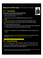
1
3.
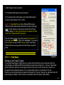
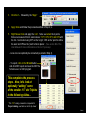
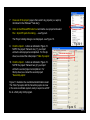
Click the R++ followed by the “Begin”
4.
Apply Scale and follow the process described in Step 2, vi.
5.
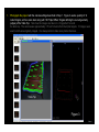
Right Mouse Click and apply the 3-2-1. Note: we named the 4 points
that were measured from 2 scale bars as: *CP1, CP2, CP3, and CP4 with
the 3-2-1 conducted using CP1 as the “origin”, CP2 as the “point to define
the axis” and CP3 as the “point to fall on plane”. (See section B4 of the
User Manual for more information on the 3-2-1 process).
- Lines can now optionally be connected (as noted in Step 3).
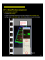
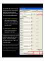
- To export, click on the 3D List button
and click DXF export and save the DXF file
for later use in a CAD program.
This completes the process
steps. Now, let’s look at
optionally “adding” some
of the smaller .15” dot Triplets
in the following slides…
* The “CP” naming convention is required for
Project Linking, used later on in this tip sheet
Slide 6