1
MSC CXB-6S / CXB-6SI
Rev. 1.8
User Manual
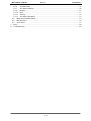
Content
1
2
3
4
5
6
General Information ......................................................................................................................... 5
1.1
Revision History ........................................................................................................................ 5
1.2
Reference Documents............................................................................................................... 5
1.3
Introduction ............................................................................................................................... 6
Technical Description ....................................................................................................................... 7
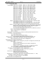
2.1
Key features.............................................................................................................................. 7
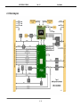
2.2
Block diagram ........................................................................................................................... 8
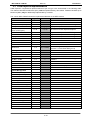
2.3
COM Express implementation ................................................................................................... 9
2.4
Functional units........................................................................................................................10
2.5
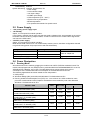
Power Supply...........................................................................................................................11
2.6
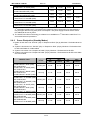
Power Dissipation ....................................................................................................................11
2.6.1
Running Mode...................................................................................................................11
2.6.2
Power Dissipation (Standby Modes) ..................................................................................12
2.7
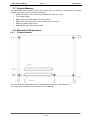
System Memory .......................................................................................................................13
2.8
Mechanical Dimensions ...........................................................................................................13
2.8.1
Compact module ...............................................................................................................13
2.9
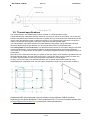
Thermal specifications..............................................................................................................14
2.10
Signal description .................................................................................................................15
2.10.1 High Definition Audio.........................................................................................................15
2.10.2 Ethernet ............................................................................................................................16
2.10.3 IDE ...................................................................................................................................16
2.10.4 Serial ATA.........................................................................................................................17
2.10.5 PCI Express Lanes ...........................................................................................................18
2.10.6 PCI Express x16Graphic Lanes .........................................................................................18
2.10.7 Express Card Support .......................................................................................................19
2.10.8 PCI Bus ............................................................................................................................19
2.10.9 USB ..................................................................................................................................20
2.10.10 LPC Bus ...........................................................................................................................21
2.10.11 LVDS Flat Panel ...............................................................................................................21
2.10.12 Analog VGA ......................................................................................................................21
2.10.13 Digital Display Interfaces ...................................................................................................22
2.10.14 Miscellaneous ...................................................................................................................25
2.10.15 Power and System Management .......................................................................................26
2.10.16 General Purpose I/O .........................................................................................................27
2.10.17 SPI Interface .....................................................................................................................28
2.10.18 Module Type Definition......................................................................................................29
2.10.19 Power and GND ................................................................................................................30
2.11
Pin List for MSC CXB-6S module (Type 2) ............................................................................31
2.12
DDI Port Pin Assignment ......................................................................................................33
1) CTRLDATA pins do have strap functionality and are sampled during power up. A high level on these
pins enables the appropriate DDI port B, C or D inside the PCH. ........................................................34
Jumpers and Connectors ................................................................................................................35
3.1
Jumpers...................................................................................................................................35
3.2
Fan Connector .........................................................................................................................36
Watchdog .......................................................................................................................................36
System resources ...........................................................................................................................37
5.1
PCI IRQ Routing ......................................................................................................................37
5.2
IRQ Lines in APIC Mode ..........................................................................................................38
5.3
Carrier Board PCI Resource Allocation.....................................................................................39
5.4
SMB Address Map ...................................................................................................................39
BIOS...............................................................................................................................................40
3 / 81