1
User Manual
USER MANUAL
No part of this documentation may be reproduced in any form whatsoever or be stored in any
data retrieval system without prior written permission of the copyright owners.
This documentation is supplied on an as-is basis. Information contained within this documentation is subject to change at any time without notice and must not be relied upon.
All company and product names are ™ or Registered Trademarks ® of their respective owners.
Windows 7, Windows Vista and Windows XP are trademarks of Microsoft Corporation.
Merging Technologies makes no warranties express or implied regarding this software, its quality, performance, merchantability or fitness for a particular purpose. The software is supplied “as
is” you, the purchaser, are assuming the entire risk of the results of using this Merging Technologies software.
In no circumstances will Merging Technologies, its owners, directors, officers, employees or
agents be liable to you for any consequential, incidental or indirect loss or damages including
loss of time, loss of business, loss of profits, loss of data or similar resulting from the use of or
inability to use the Merging Technologies hardware and or software or for any defect in the
hardware software or documentation.
© Copyright Merging Technologies Inc. 2014. All rights reserved
Merging Technologies
Le Verney 4 1070 Puidoux Switzerland
Tel: +41 21 946 04 44 • Fax: +41 21 946 04 45
www.merging.com
Contents
Introduction
Thank you!
Overview
10
10
10
What is VCube?
10
Contacting Merging
11
International Office:
11
UK:
11
USA:
11
VCube Keys & Options
Installation
Early VCube Systems
VCube Concepts
12
14
14
14
Project
14
Composition
14
Track
14
Video Track Layer
14
Audio Track Layer
14
Video and Audio Outputs
14
About This Manual
15
Assumptions
15
Conventions
15
Important Note
User Interface
16
17
Overview
17
Program Screen
18
Context Menus
19
Navigating the Interface
19
Zoom in the Timeline
20
Timeline
Synchronization
21
24
Requirements
24
Important Note
24
Quick Settings
Overview
Using Quick Settings
25
25
25
Contents :
Page iii
Quick SD Settings
26
Quick HD Settings
28
Projects
Compositions
30
30
Composition File Tab Page
30
New Composition
31
Load Selective
32
Settings Imported With Composition
33
Import
34
Import Composition and Export Changes
34
Import Layer
34
Import Images Sequence
35
AAF
38
MXF
39
OMF
39
Media Management
Media File Browser
Drag & Drop
Media Handlers
42
42
44
45
QuickTime
45
MXF
46
MPEG
46
File Extensions Supported
47
Tracks and Layers
48
Video Tracks and Layers
49
Track and Layer Order
49
Audio Tracks and Layers
50
Tracks and Layers Created Automatically
50
Adding Tracks and Layers
50
Dolby E on the Timeline
50
Transport and Navigation
Navigation
51
51
Time Ruler
51
Zoom
51
Locators
51
Transport Control
54
Transport Control Bar
54
Transport Tool
55
Go To TimeCode
57
Recording and Acquisition
Recording
58
58
Virtual VTR
58
Record Settings Tab
60
Editing
Editing in the Timeline
64
64
Clips in a Composition
64
Contents :
Page iv
Selections and Groups
64
Nudge
65
Editing Functions
65
Trim
66
Edit Context Menu
67
Motion Rectangles (PiP)
69
Watermark and Text
Watermark
Text Clip
Generated Clips
Countdown Clip
Wipe Clip
Video Test Pattern Clip
Audio Tone clip
Conversion and Rendering
Export Composition
72
72
74
77
77
79
80
81
82
82
XML
82
Conversion, Rendering and Wrapping
Convert Media Files
Render Composition
82
82
89
Convert Still Images
90
Wrap Audio
91
Wrap Audio Dialog
92
Level Magic™, from Jünger Audio
97
Jünger Level Magic Expert Settings
97
Final Check Meter
MXFix™ (Batch Export, Re-Wrapping)
99
100
MXFix Quick Procedure
101
MXFix Folders dialog
102
MXFix Wrapper Dialog
103
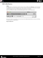
Running MXFix
107
MXFix Web Monitor
Frame Rate Management
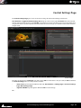
Control Settings Page
File Tab
108
111
112
113
VCube Compositions
114
Media File Browser
Locator Tab
View Tab
115
115
115
Clip Info
115
Video Clip
116
Audio Clip
119
Shortcut
122
Workspace
123
Edit
127
Contents :
Page v
Main
127
Clips
128
Layers
129
Tracks
130
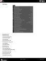
Settings
Settings Page
131
131
Preset
131
Creating Global Presets
132
Format & Sync
133
Video I/O
138
Overlay
139
Preview
141
Composition
144
Buffer & Cache
147
User Interface
148
Encryption
149
Media Settings
150
Timeline
151
Video Engine
153
Audio Engine
154
Isis Controller
156
Tool Bar
Tools and Toolpickers
Applications
Non Compensated Telecine at 24 fps
24fps Composition Chasing other Timecodes
Using the Graphic Card S-Video Output
Remote Control
VCube Chasing Pyramix Via Virtual Transport 2 in the Same PC (PyraCube)
VCube Chasing Pyramix Using Virtual Transport Via Network
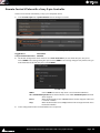
Remote Control VCube with a Sony 9-pin Controller
Synchronizing VCube to a Sony 9-pin Chase Synchronizer
Sony P2 Protocol over IP
157
157
165
165
165
166
167
167
167
168
169
169
VCube Controlled by Sony 9-pin, Chasing an LTC Source
Synchronize VCube with an LTC Source
Synchronize VCube with a VITC Source
Machine Control
VCube Controlling & Chasing a Sony 9-pin
Menus
File
Edit
Selection
Zoom
Locator
Goto
Contents :
170
171
172
173
173
175
175
176
178
178
179
180
Page vi
Transport
Overlay
Settings
User Interface
Help
Output View
Output Page Diagnostic Tools
181
181
182
183
185
186
186
System Tab
186
Buffer Tab
189
Playback Info Tab
189
Sync Status
192
Troubleshooting
195
Read Drops During Playback
195
Current FPS Reduced
195
Flickering Video Output
195
Matrox Parhelia Settings
195
Frozen Image on Matrox Parhelia Output
197
Poor HD Image Quality
198
Frame Shifting with Virtual Transport
198
Sony 9-pin Not Controlling VCube
199
Recorded Media Files have incorrect Timestamp
199
Video Playback is shifted
200
User Interface with ATI Graphic Card
201
NTSC Video Output Exhibits Some Dropped Frames with PAL Media Files
201
Apple Compatibility 2GB Limitation
202
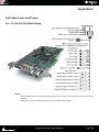
Appendices
AJA Video Cards and Plugins
203
203
LH-i - SD-SDI/HD-SDI/HDMI/Analog
203
2K - SD-SDI/HD-SDI/ 2K/ Analog
208
Xena LHe - SD-SDI/HD-SDI/Analog
213
LSe - SD-SDI/Analog
218
VS3 Control Panel
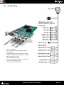
VCube Hardware Sync Connections
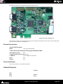
USB Sync Board Option
221
222
222
External Connections
223
Driver Installation
223
Default Shortcuts
HDTV Recorded Media
SDTV Recorded Media
Video Formats and Bandwidth
223
230
230
231
Audio
237
PullUp - PullDown
Drop Frame
Video Codecs Supported
237
237
238
Frame Rates Supported
239
Contents :
Page vii
Interchange Protocols Supported
239
Resolutions Supported
240
MJPEG Compression Ratios
242
Files Supported.
AVI 1, AVI 2 and AVI ref
MPEG Settings (MainConcept Encoder)
243
244
244
MPEG Overview
244
Export
246
Media Storage Requirements
Installation Examples
260
261
A Great Solution for Audio Post for Film
261
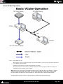
Basic VCube Operation
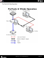
Pro Tools & VCube Operation
Pyramix, VCube and ProTools
Avid Unity and VCube
Fairlight Controlling a VCube
262
263
264
264
266
Fairlight DREAM/MFX3
266
Fairlight DREAM Satellite
266
Fairlight DREAM Station
266
Pro Tools and VCube
266
Pro Tools 6.4.1, Mac OS 10.3 and a KeySpan
266
Pro Tools HD
271
Sony 9-Pin RS422 Wiring Chart
Glossary
Index
274
278
286
Contents :
1 - viii
:
Document revision-23
Date: 2nd-April-2014
:
Page 9
Introduction
Thank you!
Congratulations on your purchase of the VCube HD Video System. More than just a powerful video solution,
VCube is part of a comprehensive range of Audio, Video and Show Control products, software and hardware. Welcome to the worldwide community of users who have already discovered the Merging Technologies advantage.
Note: IMPORTANT! - The first thing you need to do is register your software to acquire your
VCube key(s) and to be included in our user support list.
Please also subscribe to the User Forum at:
http://www.merging.com/forum/
Overview
What is VCube?
VCube is a hard-disk based video player / recorder system with real-time editing and resizing functions. It is
designed to be an easy to use, flexible, high quality, and reliable video file play out and capture device synchronizable with any time reference standard. For example:
In Sound for Picture Post-Production, ADR etc.
Theatres
Theme Parks
Museums
Trade Shows
AV Presentations
Film Festivals
are just a few of the possible applications for VCube.
VCube can operate as a standalone unit, or as part of a multi-system network, fully integrated with Pyramix or
Ovation, over standard Ethernet networks.
Like Pyramix it offers sync to PAL, NTSC, 24fps Film and all the HDTV frame rates.
The Turnkey versions of VCube are also able to sync to a different TimeCode and reference than the internal frame
rate. This enables, for example, playing in 24 fps while syncing to a 25 fps TimeCode.
Pro versions of VCube can also be controlled via the 9-pin Sony (P2) protocol by any third-party DAW system, as
well as controlling any device equipped with 9-pin remote control for capture. VCube fully supports the Merging
Technologies Virtual Transport technology.
The integrated video editor with multi-track, multi-layer features enables the VCube user to remove, add or trim
Media Files imported from a Composition (VCube native Composition or OMF. AAF, and Apple XML are optional).
VCube is able to mix different video file formats at different resolutions and frame rates in the same Timeline. It is
only necessary to specify the output format. All video Clips are resized and the frame rate compensated as necessary to this format in real time. Therefore it is possible to play out any video file at any frame rate in combination
with any other without rendering.
VCube is an open solution that can import OMF, AAF, Apple XML Compositions. VCube is also able to convert, and
render Media. A password protected watermark feature enables the administrator to tag both video and graphic
outputs. The administrator can also protect VCube settings and editing with a second password.
VCube will be your Swiss Army Knife for video !
Introduction : Thank you!
Page 10
Contacting Merging
International Office:
Merging Technologies S.A.
Le Verney 4
CH-1070 Puidoux
Switzerland
Phone: +41 21 946 0444
Fax: +41 21 946 0445
UK:
Merging UK
St Clare House, St Clare Business Park
Holly Road, Hampton Hill
Middx UK
TW12 1QQ
Phone: +44 (0) 20 894 16547
Fax: +44 (0) 870 1231747
USA:
Merging USA (Independent Audio)
43 Deerfield Road
Portland,
ME 04101-1805
United States of America
Phone: +1 (207) 773 2424
Fax: +1 (207) 773 2422
For all documentation inquiries or suggestions for improvement:
http://www.merging.com
Introduction : Contacting Merging
Page 11
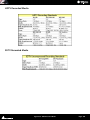
VCube Keys & Options
VCube is currently supplied with RGBA, RGB, YUY2, DV25, MJPEG, codecs. DVCPRO (50), DVCPRO-HD (100),DNxHD
and IMX/MPEG2 are optional. OMF is provided as a Timeline exchange format. MXF, AAF, and Apple XML are
optional.
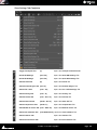
VCube Keys
VCube
VCube IO SD Composite
VCube IO SD SDI
VCube IO HD SDI
VCube IO HD SDI Dual-Link
VCube IO HD SDI Dual-Link Ex
Vcube IO HD Telecine
VCube MPEG2-SD/D10/IMX (Sony XDCam SD)
VCube DVCPro
VCube InterChange - Final Cut Pro XML
VCube InterChangeAAF
VCube HD 2K
VCube DVCPro HD
VCube MXF
VCube VC-3 (Avid DNxHD)
VCube MPEG2-HD (Sony XDCam HD)
Vcube AVC-Intra (Panasonic P2)
VCube SE (no cross-lock)
VCube LE (no cross-lock, no media generation)
VCube XE (no cross-lock)
Machine Control
Bi-Phase
Description
Enable VCube Software
Enable Xena LS
Enable Xena LH
Enable Xena 2K
IMX / MPEG2 / MPEG1 support
DVCPRO 25 / 50 support
XML Timeline exchange
AAF Timeline exchange
formats higher than 1280 x 720
DVCPRO 25 / 50 / 100
MXF file format support
DNxHD codec support
VCube Without Mykerinos
Player only
Player only
Pro option for SE, LE, XE
Pro option for Turnkey, SE, LE, XE
Introduction : VCube Keys & Options
Page 12
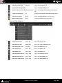
VCube Versions
Introduction : VCube Keys & Options
Page 13
Installation
Please see the VCube Installation Guide and the Installation Guides for any hardware you have purchased.
Early VCube Systems
Note: Early VCube systems may include AJA Xena LS, Xena HS or Canopus ADVX-1000 video
cards. These are no longer actively supported as of Version 2. If you have one of these cards you
may wish to contact your Merging Technologies sales partner to discuss a cross-grade solution.
VCube Concepts
Project
A Project is the top level of organization. Projects are saved with the file extension .VCube. A Project controls and
keeps track of all the various elements you are assembling at a given time. A Project always contains a Composition, viewed on the Timeline.
Composition
A Composition is any number of Clips complete with edits and fades, level settings etc. placed on a Layer in a
Track or tracks in a time relationship to each other and to the Timeline.
Track
In the Timeline Video and Audio assets are placed onto Layers within Tracks.
Video Track Layer
Video Track Layers behave in the same manner as layers in a non-linear video editor. I.e. video on the topmost
layer of the topmost track will hide concurrent video below it unless there is a compositing blend mode or
picture-in-picture mode in force.
Audio Track Layer
Audio Track Layers display the waveform for each channel in the audio media file. Thus a stereo audio track will
have two layers and a 5.1 will have six.
Video and Audio Outputs
Video
Video may be viewed via the computer graphics card or via a dedicated AJA video card. Please see: Video I/O on
page 138.
Audio
Audio may be monitored via and ASIO device, a Mykerinos card or a RAVENNA device such as a HORUS or HAPI.
The Audio output device is selected and set in the VS3 Control Panel.
Introduction : Installation
Page 14
About This Manual
Assumptions
This User Manual and the other documentation assume you are thoroughly familiar with PCs and Windows terms
and concepts. If the PC is new, please ensure the machine is working correctly before attempting to install VCube.
Note: Although VCube version 2 runs under the 32 bit versions of Windows XP, Windows Vista
and Windows 7, it does not support the “Aero” style transparency display features present in
Windows Vista and Windows 7. This will be turned off automatically for the duration of the
VCube session.
Conventions
Conventions used in this document:
Names found on screens and in menus are shown in bold. E.g. Information & Settings
Menu and sub-menu selections are shown like this:
User-Interface > Output > Show Buffer Tab
Which means:
Go to the User-Interface pull-down menu, mouse down to the Output sub-menu, mouse down to the Show Buffer Tab entry and Click.
References to VCube Settings Tabs are shown thus:
Settings : Formats & Sync : Composition Video Format : Height
Which means:
In the Settings Page accessed via Settings > Show All Settings click on the Down Arrow and Click Format &
Sync to open the Tab. In the Composition Video Format Section the Height field is the one we are interested in.
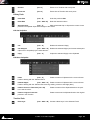
Keyboard Shortcuts are shown thus: [Ctrl + Num 9].
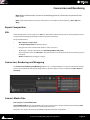
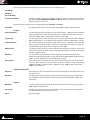
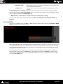
The VCube User Interface uses a number of buttons. These are dark when unchecked (inactive, not selected) and
orange when checked (active, selected) The state of these buttons is referred to as checked or unchecked.
VCube button states
In the screenshot above the Transparent Overlay Box is inactive (unchecked) and Chase TimeCode is active
(checked).
Documentation
Automatically installed with VCube and available under the Help menu or [F1], this manual is intended to be a
comprehensive reference source for all the standard features and functions in VCube.
To ensure the document is visible please uncheck TopMost in Settings > Show User Interface Tab : Display Manual Resize or use [Ctrl + Shift + Alt +P] to open the page.
All the documentation is in the Adobe Acrobat pdf format. (.pdf file extension)
In order to read the documentation you will need to have Adobe Acrobat Reader V5 or later installed on your
computer.
Other documentation can be found in the Windows Start menu in All Programs > VCube > Docs. Please check
for the most recent versions at:
http://www.merging.com
Introduction : About This Manual
Page 15
Note: All features described in the documentation are available in the Advanced Mode. If the
user-interface is set to Simple Mode some features may remain hidden or unavailable. To
change the UI Mode:
User Interface > WorkSpace > UIMode: Advanced [Alt + F3]
User Interface > WorkSpace > UIMode: Simple [Alt + F1]
Navigation
In electronic form, all the Contents and Index entries and Cross-references are hyperlinks. I.e. Clicking on them
will jump to the relevant item.
ToolTips
VCube software is equipped with ‘ToolTips’. Hovering the mouse cursor over a tool icon pops-up a box with the
name of the function and the keyboard shortcut (where applicable).
Support
If you cannot find an answer to a query in the documentation, please consult the on-line support at:
http://www.merging.com
where you will find answers to F.A.Q.s (Frequently Asked Questions) and further support.
Multiple Monitors
VCube supports 2 screen extended desktop operation. Depending on the Vcube version and the hardware available, analog and digital video outputs are available to feed monitors and or projectors.
Important Note
VCube is not only a very powerful video player/recorder, it is also a highly configurable one, the User Interface as
much as the Video and Audio. Therefore screenshots in this document may differ from what you see on screen.
PLEASE DO NOT PRINT THIS DOCUMENT UNLESS ABSOLUTELY NECESSARY
SAVE TREES AND INK BY USING THE HYPERLINKS
Introduction : Important Note
Page 16
User Interface
Overview
VCube is organized with a Tabbed Page interface. Every Tab can be displayed in a broken away window, on top of
the Preview, if required, even while Preview is full screen. Classic pull-down menus complement this user interface. In VCube there are usually at least three ways of accessing everything. E.g. Menu, Icon, Tab or Keyboard
Shortcut.
To display a Page Tab separately, Double-click on its Title Label. The floating Tab Page can now be Click-anddragged anywhere on the screen(s).
To restore the Tab Page to its default position, just Double-click again on the Title Label or use the close window
X icon.
To display an individual Tab separately, [Ctrl + Double-click] on its Title Label.
To restore to the default position, just Double-click on its Title Label or use the close window icon.
Individual Tabs can also be displayed separately by a Double-clicking on their Title Labels.
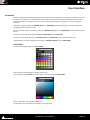
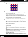
Color Picker
Several VCube Settings Tabs use a Color Picker.
Pick one of the standard colors by simply clicking on it.
Alternatively Click on Custom to edit the colors in the first row of the Color Picker.
Click in the bottom bar to choose a Hue value.
Finally, Click in the Saturation area to define the custom color.
User Interface : Important Note
Page 17
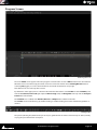
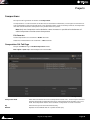
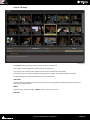
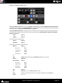
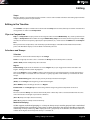
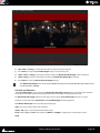
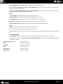
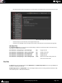
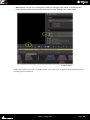
Program Screen
VCube Program Screen
The main VCube screen appears when the program is launched. This screen is NOT resizable in the conventional
Windows manner and will occupy the whole screen area of one PC monitor unless Floating Window mode is
selected ([F4] toggles). It can also be minimized or closed with control boxes at top right.
Pull-down menus are at the top of the screen.
By default the entire upper panel is a Preview video monitor. Beneath this is the Toolbar and the Timeline panel
with the Locator Bar, Time Scale (plus optional Film Footage scale) and Range Bar at the top and the Transport
Control bar at the bottom.
The Timeline area is tabbed with Timeline, Record and Output Tabs available on the left.
The Toolbar can be made ‘floating’ by double-Clicking it. Double-Clicking the header of the floating Toolbar redocks it.
Floating Toolbar
The splitter (dividing line) between the panels may be grabbed with the mouse and moved up or down, thereby
varying the space allocated to each panel.
User Interface : Program Screen
Page 18
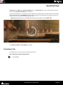
Context Menus
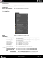
Right-click in the Preview pane or in the Timeline with the Cursor over the tracks to display contextual menus.
Note: The Timeline menu contents varies depending on circumstances.
Preview Context Menu
In Simple, Full Screen or Floating modes, several VCube functions can be accessed with a Right-Click on the preview area :
Preview Context Menu
Toggle Fullscreen Preview
[F3]
Toggles Preview Full Screen.
Toggle Floating Window
[F4]
Toggles the Preview window floating and hides the User Interface except
for broken away windows
Toggle Show/Hide Settings
[F2]
Toggles Control Settings Pages.
Toggle Burn-in Timecode
[B]
Toggles the Burnt-in TimeCode Counter Show/Hide
Toggle External TC
[Alt + B] Toggles the External TimeCode Input display Show/Hide
Toggle Mask On/Off[M]Toggles the horizontal and vertical Masking On/Off
Navigating the Interface
Whilst it is perfectly possible to operate VCube without recourse to Keyboard Shortcuts we strongly advise learning at least the basics. Changing the layout of the User Interface during operation and opening and closing the
most common Pages and Folders is much more efficient this way rather than delving in menus. The following list
gives the most commonly used Interface functions, their shortcuts and menu entries :
Display Control Settings Pages [F2]
User Interface > Toggle Show/Hide Settings
Displays the Settings and Control Pages on the right-hand side of the Preview pane. The Preview is resized to suit.
The width of the Control Settings Pages can be changed by clicking and dragging the separator.
Toggle Full Screen Preview
[F3]
User Interface > Toggle Full Screen preview
Toggle Floating Window
[F4]
User Interface > Toggle Floating Window
Makes the Preview window float and hides the User Interface except for broken away windows. You can choose
from
Refresh
[F5]
User Interface > Refresh
Toggle File Page
[F6]
User Interface > Settings Pages > Show File Page
Toggle Locator Page
[F7]
User Interface > Settings Pages > Show Locator Page
Toggle View Page
[F8]
User Interface > Settings Pages > Show View Page
Toggle Edit Page
[F9]
User Interface > Settings Pages > Show Edit Page
Open Settings Page
[F10]
User Interface > Settings Pages > Show Settings Page
Opens the Settings Page floating
Previous Settings Page
[Home]
User Interface > Settings Pages > Previous Settings
Page
Next Settings Page
[End]
User Interface > Settings Pages > Next Settings Page
Show Timeline in lower panel [F11]
User Interface Show Timeline Page
User Interface : Program Screen
Page 19
Show Record Page in lower panel [F12]
User Interface > Show Record Page
Toggle Transport Control Panel [T]
User Interface > Toggle Transport Tool
Show Preset Tab
Settings > Show Preset Tab
[P]
Zoom in the Timeline
To change the Zoom level use [Alt + Mouse wheel] or [Alt + Click into the Time Ruler and Drag].
[Alt + Drag in the Timeline] Zooms to the Region selected.
Double-click on the Time Ruler acts as Zoom All and deselect selected clip(s).
Zoom All
[Alt + 1]
Undo zoom
[Alt + 2]
Zoom In
[Alt + 3]
Zoom Out
[Alt + 4]
User Interface : Program Screen
Page 20
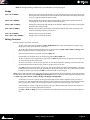
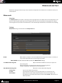
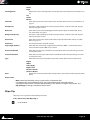
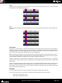
Timeline
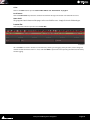
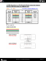
User Interface > Show Timeline Page [F11] brings the focus to the Timeline Tab below the Preview pane. Double-clicking the Timeline Tab breaks it away as a floating window.
Layer Select Area
Opacity Control
Mute
Solo
Source and Destination Rectangles
Locator Bar
Range Loop
Play Head and Time Ruler
Clip Name
Group Number
Audio Output
Audio Level Control
Vertical Zoom Control Slider
Timeline floating Tab
•
The Locator Tray is above the Timeline. Locators can be dragged with the mouse. Double-click in the
Locator tray to open the Locators page.
•
Below is the TimeCode Scale. A Double-click in the TimeCode Scale acts as Zoom Fit [Alt + 1] and Deselects All Clips.
•
Underneath is the Range Tray. The Range can be dragged and trimmed with the mouse. Double-clicking
in the Range Tray sets the Range from the Start to the End of the Composition.
•
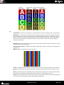
Video Track 1 has 2 Layers and is locked, Track 2 has only one Layer.
User Interface : Timeline
Page 21
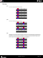
•
Layer 1 is selected in Video Track 1. Track 1 is also selected. Sting Clip is set to Fade In.
•
Opacity of every Layer is set to full (100). Layer 2 in Video Track 1 has been modified in Size or Position
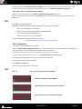
•
In Video Track 2 the Red / Blue Clip (crosshatched or “zebra” striped) means the Media is missing but
despite this, the Clip can still be edited.
•
Audio Clips and Video Clip Sting... belong to the same group, G2.
•
Click and drag on the Vertical Zoom Control to vary the Track height.
•
Click on the Audio Output indicator to pop-up a list of all available audio outputs.
Note: Right-clicking in a blank area of the Timeline pops-up a context menu. Right-clicking on a
Clip pops-up a different context menu.
Note: In the Video Layer header, the button labeled Normal and associated drop-down are for a
future feature under development.
Film Footage Ruler
Settings > Show Timeline Tab : Feet Ruler
When checked, the Show Feet Ruler entry shows the Film Footage Ruler above the TimeCode Scale.
The Footage Ruler Settings dialog can be accessed by Right-clicking the Film Footage Ruler or via Settings >
Show Footage Ruler Options Dialog
Footage Ruler Options dialog
Footage type
16mm
When checked Film Feet are counted in units of 40 Frames
35mm
When checked Film Feet are counted in units of 16 Frames
Frame Type
The Frame Type drop-down menu allows for the cadence and temporal subdivisions of the feet & frames counter
to be changed independently of the Composition frame rate or incoming timecode. By far the most popular footage counter temporal rate is 24 fps which corresponds to a standard 35 mm frame rate, but you may also need to
compensate for picture that has been accelerated frame-for-frame (24=>25 fps) or pull-down frame rates (23.98
film) so that feet & frame values actually match frames in the Timeline regardless of the Composition’s or incoming
TimeCode’s frame rates. The Use Composition frame rate button locks the feet & frames counters to the Composition frame rate.
Use Composition frame rate When checked the time-base is the same as the Composition Frame Rate. When
unchecked the time-base can be selected from the drop-down list above.
User Interface : Timeline
Page 22
First foot position
The Time field enables an offset to be entered if required. For example when a 15
foot (10 second) leader starting at 01:00:00:00:00 precedes the first frame of
action and the first frame of action should show 0.00 Feet & frames at
01:00:10:00.00 TimeCode then enter an offset of 01:00:10:00:00
Reset
Reset Feet Every Hour
When checked, the footage counter and footage ruler will return to 0.0 after every
hour. This is useful if there are several film reels in a composition with first frame of
picture of each reel at the beginning of each hour. E.g. reel one starts at
01:00:00:00:00, reel two at 02:00:00:00:00 and so on. Thus enabling each reel to
count from 0.00 feet.
User Interface : Timeline
Page 23
Synchronization
Settings
All the relevant synchronization settings can be found in the Settings > Show Format & Sync Tab.
Requirements
In order to be synchronized properly VCube requires the following as a minimum:
•
A Chase TimeCode Source (Virtual-Transport: Network, Sony 9-pin (P2) protocol or external : LTC, VITC,
MTC)
•
A TimeCode Clock Reference (VCube's Video Reference In BNC connector or internal Mykerinos' clock)
•
A Clock for audio sampling rate sync. (Internal: Mykerinos, or external: Video, WordClock, or Audio Input)
TimeCode Sources
•
LTC (VCube XLR connector) Network (RJ45 Ethernet connection)
•
VITC (VCube Video Reference In BNC connector)
•
Sony 9 pin protocol (RS-422 serial port). RS-232 on COM1 port is also possible.
•
MTC (MIDI TimeCode from a suitable hardware MIDI interface or IP MIDI etc.)
Note: that an Ethernet connection used as a source of TimeCode is also able to feed VCube with
an SD stream from a Video Server simultaneously.
Virtual Transport 2
TimeCode Chase, whilst effective, is slow. Virtual Transport 2 enables VCube (and Pyramix) to be locked together.
In effect this is a built in Chase Synchronizer for VCube.
VCube SE with AJA Card and WITH USB Sync card (PRO option):
Clock Master ON:
•
VCube can Chase on LTC
•
VCube can Chase a Sony 9-Pin Machine TC
•
VCube can Follow VT2
Clock Master OFF
•
VCube can Follow VT2 ("PyraCube" Setup)
VCube SE Mode with AJA Card and WITHOUT USB Sync (PRO option):
Clock Master ON:
•
VCube can Chase Sony 9-Pin Machine TC
•
VCube can Follow VT2
Clock Master OFF
•
VCube can Follow VT2 (PyraCube Setup)
XE/LE/SE Mode without AJA Card and WITHOUT USB Sync (PRO option):
•
VCube is NEVER Clock Master and TC Master. VCube follows VT2 without using its internal Chase Synchronizer because both Clock and TimeCode is sourced from VT2.
Important Note
In order to ensure optimum sync; the Mykerinos, AJA and USB Sync cards must all be locked to the same Video
Reference.
Synchronization : Timeline
Page 24
Quick Settings
Overview
In order to ensure that VCube is as versatile as possible there are a very large number of settings. To make it easier
to configure VCube for common formats there are two Quick Settings options.
These two dedicated Settings panels enable one click setting of the Video Input format, the Composition format,
the TimeCode frame rate and the Video Output format. When VCube is configured by using Quick Settings it
behaves like a VCR for the format selected. Quick Settings can also form a useful basis for more complex configurations.
Using Quick Settings
Set Up
To set up VCube using Quick Settings:
•
Open the relevant Quick Settings Page using :
Quick SD Settings for Standard Definition formats: Settings > Quick SD Settings [Alt+F5]
Quick HD Settings for High Definition formats: Settings > Quick HD Settings [Alt+F6]
•
Ensure that the two or three Reference Sources are set appropriately.
•
Click on the Apply button for the appropriate format.
•
Verify in the Current Configuration section that the settings are as you desire
•
Click on Close to finish and close the Page
Please see subsequent pages for screenshots and details.
Quick Settings : Overview
Page 25
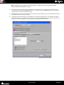
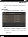
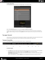
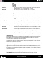
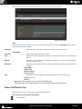
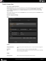
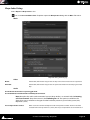
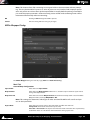
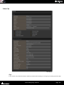
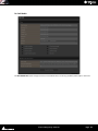
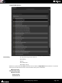
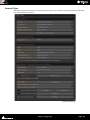
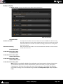
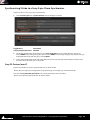
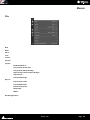
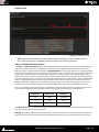
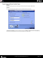
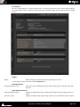
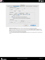
Quick SD Settings
Quick Standard Definition Settings page
Current Configuration
The Current Configuration section summarizes the current state of VCube in terms of:
Size :
Shows the number of horizontal and vertical pixels.
Field Order:
Shows Progressive Frame for non field based formats or field order and type.
Pixel Aspect Ratio
Shows the shape of pixels as a ratio
Composition frame Rate
E.g. FILM (23.98 fps)
TC Frame Rate
E.g. FILM (23.98 fps)
Mykerinos Video Ref Format: E.g. PAL (625 50.00 Hz)
Audio Sampling Rate
E.g. 48000 Hz
Reference Source
The Reference source Panel features two or three drop-down lists:
Video Reference Source
Field shows the current Video Reference source. Click on the down arrow to select
an alternative. (This line is only present when a Video card is fitted.)
Quick Settings : Using Quick Settings
Page 26
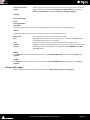
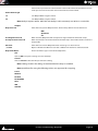
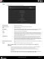
Audio Ref
Field shows the current Audio Reference source. Click on the down arrow to select
an alternative.
TC Clock Ref
Field shows the current TimeCode Reference Source. Click on the down arrow to
select an alternative.
Note: Except in exceptional circumstances it is highly desirable, if not essential, that all the references are the same and, ideally, sourced from external video syncs.
PAL
PAL 4/3 D1
PAL 4/3 DV
PAL 16/9 D1
PAL 16/9 DV
NTSC
NTSC 4/3 D1
NTSC 4/3 DV
NTSC 16/9 D1
NTSC 16/9 DV
Note: The terms PAL and NTSC are not strictly accurate in the context of Digital Video but are
used commonly as a convenient shorthand to differentiate between European and US standards.
Quick Settings : Using Quick Settings
Page 27
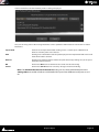
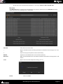
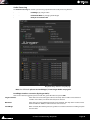
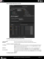
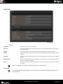
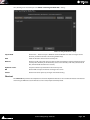
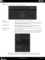
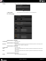
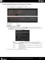
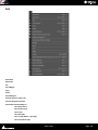
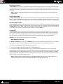
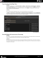
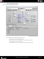
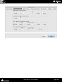
Quick HD Settings
Quick High Definition Settings page
Current Configuration
The Current Configuration section summarizes the current state of VCube in terms of:
Size :
Shows the number of horizontal and vertical pixels.
Field Order:
Shows Progressive Frame for non field based formats or field order and type.
Pixel Aspect Ratio
Shows the shape of pixels as a ratio
Composition frame Rate
E.g. FILM (23.98 fps)
TC Frame Rate
E.g. FILM (23.98 fps)
Mykerinos Video Ref Format: E.g. PAL (625 50.00 Hz)
Quick Settings : Using Quick Settings
Page 28
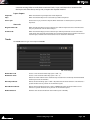
Audio Sampling Rate
E.g. 48000 Hz
Reference Source
The Reference source Panel features two or three drop-down lists:
Video Reference Source
Field shows the current Video Reference source. Click on the down arrow to select
an alternative. (This line is only present when a Video card is fitted.)
Audio Ref
Field shows the current Audio Reference source. Click on the down arrow to select
an alternative.
TC Clock Ref
Field shows the current TimeCode Reference Source. Click on the down arrow to
select an alternative.
Note: Except in exceptional circumstances it is highly desirable, if not essential, that all the references are the same and, ideally, sourced from external video syncs.
Mode
The three Mode buttons enable video card memory usage to be optimized depending of the type of HD media
recorded on tape.
DVCPRO-HD and HDV require specific settings to achieve maximum performance in Record and Playback.
Quick Settings : Using Quick Settings
Page 29
Projects
Compositions
The top level of organization in VCube is the Composition.
A Composition is a set of instructions to VCube. These include format information, screen layout and an EDL indicating what Media is to be played and when. It also determines fades, levels and other parameters. A Composition
does not contain Media Files. Compositions are portable between systems.
Note: Only one Composition can be loaded at a time. However it is possible to load elements of
other Compositions into the current Composition.
File Extension
Vcube Compositions are saved with a .VCube extension.
Video Files in VCube format are saved with a .cube extension.
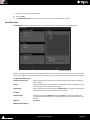
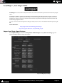
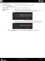
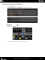
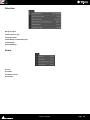
Composition File Tab Page
To open the File Tab Page in VCube Compositions mode:
File > Open or [Ctrl + O] or the File Open Icon in the Toolbar:
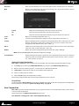
File Page - floating
Composition Path
Field shows the Path to the current Composition location. The ... button opens a browser
which enables VCube Composition files to be selected from local hard disks or via a network. This Composition Path is also used when a Composition is Saved or Saved As.
Up
Arrow moves up one level in the file hierarchy.
Refresh
Updates the list of Media Files in a specific location. [F5]
Projects : Compositions
Page 30
Recursive
When checked all Media Files in the Folder will be shown including those in sub-folders
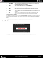
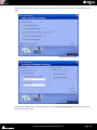
New
Opens a new Composition with the current settings. [Ctrl + N]. If a Composition is already
open then a warning dialog appears:
VCube Save Warning dialog
Cancel
Aborts the new Composition and returns to the current one
Yes
Saves the current Composition and opens the new one.
No
Closes the current Composition without saving it and opens the new one.
Load
Opens a pre-existing Composition. [Ctrl + L]
Save
Saves the current Composition using the current Composition name. [Ctrl + S]
Save As
Opens a Windows browser to enable the Composition to be with a new name or to a new
location. This feature is useful since it enables you to save many versions of the same
Composition with different names. [Ctrl + Shift + S]
Close
Aborts the current Composition. Any edit decisions made since the last time the Composition was saved are discarded. [Ctrl + Shift + Q]
Delete
Deletes the selected Composition from the hard drive. [Shift + DELETE]
Note: The associated Media Files remain on the mass storage.
Load Selective
Enables Composition objects or properties to be imported into the current one. A dialog
determines how the selection will be imported into current one. [Ctrl + Shift + L] Please
see: Load Selective on page 32
Open an Existing Composition
File > Open or [Ctrl + O] or the File Open Icon in the Toolbar opens the VCube Compositions Browser Page:
1.
If the File page is showing the Media File Browser page switch to the VCube Compositions page.
2.
Browse and select a folder using the ... button to open a Windows File Browser
3.
If Recursive is checked then all files in all sub-folders will be displayed.
4.
Click on a Composition to select it.
5.
Click on Load to open the Composition in VCube
Alternatively, simply Double-click on the desired Composition name in the list.
Drag & Drop
It is also possible to drag and drop Compositions and Media Files into the Timeline directly from normal Windows
Browser windows. For behaviors please see: Drag & Drop on page 44
New Composition
File > New closes the existing Composition (if any is open) and creates a new Composition with the same settings
as the last open Composition.
Alternatively open the VCube Compositions Browser Page
User Interface > Settings Tabs > File > Show VCube Files [Ctrl + O] .
Projects : Compositions
Page 31
1.
Browse and select a destination folder
2.
Click on New
3.
The New Composition opens with the same settings as the last Composition opened
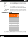
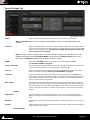
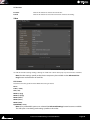
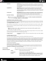
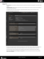
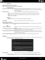
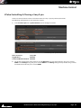
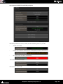
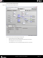
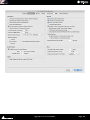
Load Selective
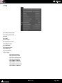
Load Selective enables Composition objects or properties to be loaded into the current Composition.
Load Selective dialog
Options are grouped into boxes. Each black box header has a button which, when checked, turns on import of the
properties or objects selected in the box itself. Selection can only be made when the box title button is checked.
Composition Properties
Format & Frame Type
When selected Format and Frame rate will be imported when the new Composition is loaded.
Range
When selected the current Composition range markers will be overwritten by new
values when the new Composition is loaded.
Watermark
When selected the current Composition Watermark (If any) will be overwritten by
the Watermark the new Composition when it is loaded.
Locator
Keep Existing
Mutually exclusive with Replace. Existing Locators can either be retained and
merged with the imported ones or replaced by the ones in the Composition to be
loaded.
Replace
See above
Main VCube Settings
Projects : Compositions
Page 32
Workspace
When selected the Workspaces in the current Composition will be overwritten
with the ones in the Composition about to be loaded.
Shortcut
When selected the Keyboard Shortcuts in the current Composition will be overwritten with the ones in the Composition about to be loaded.
Clips
From Layer
All
When selected All Layers in the current Composition will be imported.
Layer...
All layers present in the Composition to be imported are listed. When the All button is not checked you can select any of the Layers listed to be imported by clicking on the buttons.
Timecode
Original Timecode
At Timecode
When checked Clips will be imported at the original TimeCode in the source Composition.
When checked you can enter a Timecode starting point in the field. If this option is
used then Locator positions will also be shifted.
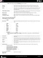
Settings
Overlay
TC Enable
Ext TC Enable
TC Position & Size
TC Color
TC Transparency Enable
Mask Enable
Mask Size
Preview
Deinterleave
Video Frame
Safe Area
Composition
Lock Editing
Watermark Enable
Copyright
Position
Watermark Color
Media Path Link to Composition Path
Auto Wipe & Auto Countdown
Format & Sync
Audio Sampling Rate
Video Size
Field Order
Pixel Aspect Ratio
Saved in
Composition
Settings Imported With Composition
X
X
X
X
X
X
X
X
X
X
X
X
X
X
X
X
X
X
X
X
X
Composition Saved Settings
If you use the Load option all Settings in the table above will be changed as required to those saved in the Composition being opened. If you use the Load Selective option it is possible to import just Composition Settings
such as Workspaces, Keyboard Shortcuts and Synchronization.
Projects : Compositions
Page 33
Import
Import Composition and Export Changes
This feature creates an EDL reflecting the differences between two versions of a project.
An .EDL file is created in the Composition folder. This file can also be opened in a text editor e.g. Notepad.
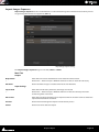
Import Layer
A particular layer or a selection of layers can be imported from a VCube Composition into the current one. [Ctrl +
Alt + L]
Layers Import dialog
Properties
When checked, also imports the individual Clips Properties (Locked, Invert Fields, Invert
Color...)
Clips
When checked Clips in the selected Layer(s) will be imported.
From Layer
All Layers available for import from the source composition are listed. Checked Layers will
be imported.
Original Timecode
When checked Clips will be imported at their Original Timecodes.
At Timecode
When checked a Timecode start value can be entered in the field. When unchecked the
value shown is the beginning of the first Clip in the selected Layer(s).
Projects : Import
Page 34
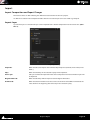
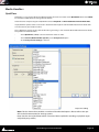
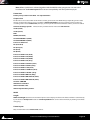
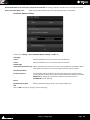
Import Images Sequence
Import Images Sequence creates a Video file from a set of Individual Image Files numbered consecutively. A wide
range of Image file formats are supported. [Ctrl + I]
Import Images Sequence dialog
The Import Images Sequence Page has two Tabs, Main and Video.
Main Tab
Output
Output Path
Field shows the current Path where the new Video File will be written.
...
Click on the ... button to open a Windows browser to select an alternative directory.
File Name
Click in the field and type a suitable name for the new Video file.
Input Settings
Import Path
Field shows the directory where the still images are located
...
Click on the ... button to open a Windows browser to select the directory where the
source image files are located.
File Format
Field shows the image file format to be imported. Click on the down arrow to choose the
required format from the list below.
Proceed
Click on Proceed to begin the Import and Conversion process
Cancel
Click on Cancel to abort the Import
Projects : Import
Page 35
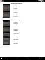
Still Image File Formats Supported
Supported File
Extensions
.dpx
.yuv
.yuv8
.yuv10
.yuv16
.bmp
.png
.jpg
.jpeg
.j2k
.psd
.tga
.gif
.wmf
.tif
.tiff
.pcx
.mng
.jng
.ico
.wbmp
.emf
.jbg
.jpc
.pgx
.ras
.pnm
.pgm
.ppm
Description
Digital Moving Picture Exchange (DPX)
YUV RAW
YUV 8 BIT RAW
YUV 10 BIT RAW
YUV 16 BIT RAW
Microsoft Bitmap
Portable Network Graphics
Joint Photograpic Experts Group
Joint Photograpic Experts Group
JPEG 2000
Adobe Photoshop File
Targa Graphic File
Graphics Interchange Format
Windows Metafile
Tagged Image File Format
Tagged Image File Format
PCX
Multiple Image Network Graphics
Multiple Image Network Graphics
Icon File
Wireless Bitmap
Windows Metafile
JBG
JPEG 2000 Code Stream
PGX
Sun Raster Images
Portable Bitmap
Portable Bitmap
Portable Bitmap
Projects : Import
Page 36
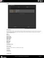
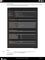
Video Tab
Import Images Sequence dialog
File Format
Field shows the Output File format selected currently. Click on the down arrow to select
from:
CUBE
*. Cube
AVI
*.avi
MPEG
*.mpg
MPEG
*.mpeg
MPEG
*.m2v
MPEG
*.m1t
MPEG
*.m2t
MXF
*.mxf
QuickTime
*.mov
Frame Rate
The field shows the Frame Rate selected currently. Click on the down arrow to select an
alternative.
Compression
The field shows the type of Compression selected currently. Click on the down arrow to
select an alternative. The exact composition of the list will depend on options purchased.
Width
The field shows the Width of the output Video in pixels. Click in the field to enter a new
value manually.
Height
The field shows the Height of the output Video in pixels. Click in the field to enter a new
value manually.
Frame Layout
Field shows the current setting. Click on the down arrow to select an alternative:
Progressive Frame
2 Fields (Interleaved - Lower First)
2 Fields (Interleaved - Upper First)
2 Fields (Separate - Lower First)
Projects : Import
Page 37
2 Fields (Separate - Upper First)
Single Field
Word Length
Fixed at 8 bits currently
Bit Format
Down Sampling
Field shows the current color sub-sampling scheme. 4.2.2 is the default.
One of the next two entries is shown as appropriate.
(Up Conversion Mode)
Field shows current conversion mode. Options will vary with the Pixel Aspect Mode setting. E.g. Anamorphic, Letterbox, Pillarbox or None
(Down Conversion Mode)
Field shows current conversion mode. Options will vary with the Pixel Aspect Mode setting. E.g. Anamorphic, Letterbox, Pillarbox or None
Pixel Aspect Ratio
Field shows the current Pixel Aspect Ratio and the format associated with this. Click on
the down arrow to select an alternative.
Resize Quality
Field shows the resizing algorithm selected currently. Click on the down arrow to select
an alternative.
Nearest neighbour
Fastest but poor quality
Linear (Bi Linear)
Fast and poor quality
Cubic
Slow but very good quality
Lanczos
Very Slow but excellent quality
Supersampling
Slow but very good for large downscaling
Advanced Settings
The button is only available when MJPEG or Avid: VC-3/DNxHD are selected as the Compression scheme or when MPEG is selected in File Format. A dialog appears with compression settings.
Proceed
Click on Proceed to begin the Import and Conversion process
Cancel
Click on Cancel to abort the Import
Notes
•
When either QuickTime or MJPEG codecs are chosen, Progressive Frame must be selected in Frame
Layout to ensure QuickTime player compatibility.
•
Frame Rate must be set to match the frame rate of the Composition where the generated Video file is to
be used.
•
Compression allows the user to select the CODEC used to generate the new Media File(s). Depending on
the chosen CODEC, it is possible to adjust the Compression Settings.
•
For full details about the MPEG Settings, please refer to the dedicated section. We recommend using only
regular Format Types in the Basic Settings dialog for trouble free operation.
•
MJPEG codec - A value of 100 corresponds to an average 1/3 compression ratio, and a value of 50 corresponds to an average 1/20 compression ratio.
Still Image Import
To import a single still image (not a sequence) into the Timeline, use Files > Import > Media File Browser. Use the
browser to select the image to Import and use an appropriate option to place it in the Timeline. A 5 seconds Clip
will be created from a single frame image. Alpha Channel (transparency) is supported.
AAF
VCube can import projects in AAF (Advanced Authoring Format).
About AAF
AAF is a set of specifications for project interchange (.aaf ) files. Media files can be embedded or referenced by link.
Note that VCube only handles Media Files referenced by link currently.
Projects : Import
Page 38
AAF Import follows the Interchange Import Settings. These help deal with AAF projects which contain large
numbers of files, improving project opening times etc.. Please see: InterChange Import on page 151
[Alt + O]File > Import > Composition (Create New)
If VCube cannot find a Media File the VCube: Searching for Media File Tab pops-up.
Use this to point VCube at the file location(s). Cancel opens the Composition with the missing Media shown as
zebra Clips.
MXF
MXF (Material eXchange Format).
The VCube MXF Module has full support (playback, render, record up to 30 fps) for:
•
D10 / Sony IMX (MPEG-2 in SD format)
•
MPEG-2-HD / Sony XDCAM HD (MPEG-2 in HD 1080i format)
•
VC-3 / Avid DNxHD (in HD 1080i format)
•
AVCIntra / Panasonic P2 (class 50 and 100)
For the latest MXF interchange information please see:
http://forum.merging.com/viewtopic.php?f=23&t=2094
MXF Configuration
To record or render an MPEG-2 flavour in MXF:
Select the Custom (Media Handler Specific) codec. This will automatically select the D-10 (Sony IMX) MPEG-2 flavour for SD formats, and the MPEG2-HD (Sony XDCam-HD) for HD formats.
To record or render in VC-3 or AVC-Intra simply choose the codec in the codec list.
In Video Advanced Settings, Aspect ratio can be Transparent, Force 4:3 or Force 16:9.
A checkbox enables WSS (Widescreen Signaling) on the first visible line.
To record audio embedded in the MXF file:
Select MXF in the Audio tab
16-bit and 24-bit PCM formats are supported.
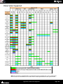
OMF
[Alt + O]
File > Import > Composition (Create New)
(Yellow) The Clip is a rendered effect.
(Green) VCube can render the effect in realtime.
(Red) The VCube does not support the effect.
Projects : Import
Page 39
Note: The Fx icon shows when an imported Clip has an effect. The color of the icon denotes
VCube treatment of the effect as above.
1.
If the path to media is included in the Composition, VCube asks the user to specify a network location for
those Media Files: Workspace/OMFI Media Files/... or a specific user path. If OMF Media Files are on the local
storage, press Cancel when the dialog appears.
2.
If the Media Files remain unlocatable, the VCube software looks for Media Files in the sub-folders of the Composition file location on the local storage.
3.
Lastly VCube uses the database to re-link Media Files. If the path to Media Files is not available in the OMF
Composition, then the Scan function must be used to generate the OMF Media Files data base. The first scan
process can take a very long time on a big media server storing thousands of files.
Export Settings - Current dialog
Projects : Import
Page 40
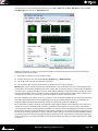
If some media files cannot be found by VCube a dialog is displayed.
VCube Preferred Search Directories dialog
Here, one or many paths to the missing Media Files can be specified to allow VCube to reconnect the needed
Media Files.
Import Path
Shows the last Import Path added. Clicking on the ... button opens a Windows File
browser to enable paths to be selected.
Add
Clicking on the Add button adds the path displayed in the Import Path field to the list of
Paths which will be searched.
Remove
Clicking on the Remove button deletes the path selected (by clicking on it) in the panel
below the Import File field.
OK
Click on the OK button to commence the search and close the dialog.
Cancel
Click on the Cancel button to cancel any changes and close the dialog.
Note: The VCube Preferred Search Directories dialog can also be reached directly from the
Settings Menu. It enables VCube to re-link Media Files spread over different workspaces or servers.
Projects : Import
Page 41
Media Management
Scope
VCube supports Video only, Video + Audio, Audio only, single Still Image and Still Image Sequence Media Files.
VCube has a pair of File management Tabs for managing Compositions and Media Files.
Media Files can dragged and dropped into the Preview screen or the Timeline. Please see: Drag & Drop on
page 44
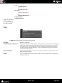
Media File Browser
To open the Media File Browser select File > Import > Media File Browser or Ctrl + Shift + O or choose the
Media File Browser Icon in the Toolbar :
Media File Browser
Navigate to the Drive, Folder or Network Drive / Folder containing the Media using the ... button which opens a
conventional Windows Browser. Then double-click on any of the Folders displayed in the main area to view the
Media Files.
Double-clicking on a Media File will insert it as a Clip into the Composition Timeline at the current Playhead position on the selected Track/Layer. If an Audio Track / Channel is selected currently then a Video Media file Clip will
be inserted on the first Video Layer above the Audio Tracks in the Timeline.
•
To add a Clip at the end of the last Clip on the selected Layer: Shift + Double-click. If no Layer is selected
a new one will be created.
•
To add a Clip at the current Playhead position in selected Layer: Double-click. If no Layer is selected a new
one will be created.
Media Management : Media File Browser
Page 42
•
To add a Clip at the current Playhead Position in a new Layer: Control + Shift + Double-click
Recursive
If the Recursive button is checked then all Media Files in the Drive or Folder listed in the File Path field will be
listed in the main area, including those in Sub-Folders.
Media File Browser- Recursive
File Path
Field shows the current Path
...
Opens a Windows browser to change the Path to a location on local storage or via a network.
^
Up arrow steps up the path tree to the root directory.
Refresh
Updates the list of Media Files in the current location [F5]
Recursive
When checked all Media Files in the folder specified will be shown including those in subfolders.
Load
Opens the Create New Composition dialog. [Ctrl + L]
VCube Create New Composition dialog
Cancel
Aborts the Load
Media Management : Media File Browser
Page 43
Yes
Closes the current Composition with a dialog inviting Save it if it has been
changed, then opens a new Composition with the same Settings as the previous
Composition.
No
Places the selected Media File on the selected Layer at the current Playhead Cursor
position.
Load & Auto-Config
Loads the selected Media File in a new Composition and sets Composition settings from
the Media File properties. [Shift + L]
Place to Cursor
Pastes the selected Media File into the selected Layer at the current Playhead cursor position.
Place at Original Timecode
Pastes the selected Media File into the selected Layer at its original TimeCode location.
Place in New Layer at Cursor
Pastes the selected Media File into a new Layer at the current Playhead cursor position.
Place in New Layer at Original Timecode Pastes the selected Media File into a new Layer at its original TimeCode location.
Place in New Track at Cursor
Pastes the selected Media File into a new track at the current Playhead cursor position.
Place in New Track at Original Timecode Pastes the selected Media File into a new Track at its original TimeCode location.
Note: Media Files can also be drag-and-dropped into the Timeline.
Note: Still images are stored in RAM when dropped in the Timeline. The Alpha channel is preserved. The Convert Still Image function [Ctrl + I] is the preferred option for numbered still
image Sequences. The Alpha channel is not preserved when image sequences are converted
into video Clips.
Drag & Drop
Drag & Drop of Media Files from Windows Explorer browser windows is supported as follows:
Drop Into Preview Screen
When the file is dropped the current Composition will be closed (after a confirmation dialog is accepted). A new
Composition is then created to suit the characteristics of the Media File being dropped. (Image Size, Frame Rate,
Aspect Ratio, Interl;acing...) The Media will be placed at its original TimeCode in the Timeline.
Drop Into Timeline
Drag & Drop into the Timeline adds Media to the current composition.
If more than one file is dropped they are placed in sequence in the Timeline.
Place to Cursor
Place to Cursor is the default behavior. The Media will be placed at the current cursor position in the Timeline.
Insert Mode
If the Ctrl key is held down while dropping the file(s) the files are inserted at the Cursor position and all subsequent clips are rippled.
Enqueue Mode
If the Shift key is held down while dropping the file(s) the files are placed after the last Clip in the Composition or
at the current TimeCode if the Composition is empty.
Media Management : Drag & Drop
Page 44
Media Handlers
QuickTime
QuickTime is a very popular file format (Media Handler) for audio and video media. QuickTime 7.4 or above MUST
be installed to allow VCube to manage this file format.
VCube features complete support of QuickTime for both Playback and Record/Render/Convert Media Files.
Any QuickTime specific codec can be used in VCube for both Playback and Record/Render/Convert Media Files
once installed on your VCube machine.
To use QuickTime specific codecs with VCube when generating a new media file (Record/Render/Convert Media
Files), follow the method below:
•
Select QuickTime (*.mov) as the File Format for video or audio.
•
Select Custom (Media Handler Specific) as the Compression option
•
Set the Compression Settings as desired.
Compression Settings
Note: The list shown above includes a number of downloaded options. Please refer to the specific codec documentation for settings options.
Note also that some QuickTime codecs are not real-time capable for recording or playback (especially third-party codecs)
Media Management : Media Handlers
Page 45
Note: Selecting QuickTime as the file format for both video and audio generates a single QuickTime file including both video and audio.
Note: When using the H264 codec for rendering or conversion, the Keyframe and Data Rate limitation must be unchecked. Please check also that the frame rate reflects the Composition frame
rate. VCube also features some codecs (DVCPRO / DVCPRO-HD / MJPEG / YUY2) that may also be
used to produce QuickTime files. In these cases, select the desired codec directly from the
Record/Render/Convert Tabs and double check that the picture geometry, the Field Order and
the Pixel Aspect Ratio match the specific codec requirements. Otherwise Record/Render/Convert may abort.
MXF
VCube supports standard definition and high definition MXF formats for playback at NTSC or PAL frame rates.
SD Files must be encoded with UYVY, DV, DVCPro 50 (dv50), MJPEG, or D-10 (AKA Sony IMX) codecs.
HD files must be encoded with DVCPro 100 (dv10), VC-3 (aka AVID DNxHD), AVC-Intra (aka Panasonic P2), or
MPEG2-HD (aka Sony XDCAM-HD) codecs.
VCube can render or wrap MXF files using all the supported codecs listed above. Due to real-time constraints,
Record is not available for AVC-Intra.
To render [Ctrl + R] an MXF file in VCube:
•
Select MXF as the File Format for both video and audio.
•
Select one of the available codecs for video Compression. For Sony XDCAM or XDCAM-HD, Advanced Settings will enable you to select the flavour of MPEG-2 and the bit rate.
•
Audio settings are available via the Advanced Settings dialog box.
Note: VCube can record both video and audio multiplexed in a single MXF file when MXF is
selected as the File Format for both Video and Audio.
MPEG
VCube uses the Mainconcept MPEG Encoder. Please see: MPEG Settings (MainConcept Encoder) on
page 244
Media Management : Media Handlers
Page 46
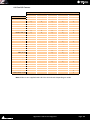
File Extensions Supported
Supported File
Extensions
.cube
.avi
.gen
.omf
.om
.mov
.qt
.bmp
.jpg
.jpeg
.tif
.tiff
.png
.gif
.emf
.tga
.mng
.jng
.psd
.pcx
.wbmp
.j2k
.jp2
.j2c
.jbg
.jpc
.pgx
.pnm
.pgm
.ppm
.wmv
.mp4
.mpg*
.mpeg*
.m1v
.mpe
.m2v*
.mpv2
.m2t
.vob
.mxf*
.aaf*
.xml*
.dv
.dif
.aif
.mpa*
.wav
.bwf
.pmf
.ac3
.sd2
.sdii
Description
VCube native format
Audio Video Interleave. AVI is defined by Microsoft. AVI
is the most common format for audio/video data on the PC.
AVID Nitris file format
AVID: Open Media Framework
AVID: Open Media Framework
Apple QuickTime
Apple QuickTime
Microsoft Windows Bitmap file
Jpeg
Jpeg
Tagged Image File Format (owned by Adobe,
created by Aldus). It's a bitmap raster file format
Tagged Image File Format (owned by Adobe,
created by Aldus). It's a bitmap raster file format
Portable Network Graphics
A Turbo-Studly Image Format with Lossless Compression
CompuServe graphics interchange format
Microsoft Enhanced Metafile
Truevison: Targa image file formats
Multiple-image Network Graphics :
A PNG-like Image Format Supporting Multiple Images,
Animation and Transparent JPEG
JPEG Network Graphics with Alpha channel
Abode Photoshop
PC Bitmap File Format
Wireless Bitmap File Format
JPeg 2000
JPeg 2000
JPeg 2000
Raster Image File Formats
JPEG-2000 Code Stream Syntax
Portable graymap format (gray scale)
Portable BitMap
Portable GreyMap
Portable PixMap
Microsoft Windows Media Video
MPEG (Moving Pictures Experts Group) 4 File (.mp4, .mpe)
Moving Pictures Experts Group
Moving Pictures Experts Group
MPEG (Moving Pictures Experts Group) Layer 1 (.mp1)
Destiny MPE Secure Audio
MPEG (Moving Pictures Experts Group) Layer 2 (.mp2)
MPEG Audio Stream, Layer II
HDV file format
DVD file format (Mpeg 2)
the Material eXchange Format
Advanced Authoring Format
Apple Final Cut Pro XML
Digital Video File Formats
Digital Video File Formats
Audio Interchange File
MPEG Audio Stream, Layer II
WAVE File Format
Broadcast wave
Pyramix media file format
AC3
Sound designer
Sound designer
Record / Render /
Convert
Yes
Yes
Yes
Yes*
Yes*
Yes*
Yes*
Yes
Yes*
Yes
Yes
Yes
* Optional feature
Note: A single Still Image is imported as a 5 seconds Clip. A sequence of numbered Still Images is imported one
images per video frame. Imported Still images are loaded in RAM.
Media Management : Media Handlers
Page 47
Tracks and Layers
Each Composition includes a number of Video and Audio Tracks on which audio and video Clips can be placed.
Blocks representing placed or recorded Clips will appear on the Track as soon as a Clip has been placed. The Track
itself extends horizontally beneath the Time Scale bar, and multiple Tracks are stacked vertically.
Video Track Number
Track Mute
Track Solo
Layer Number
Opacity
Compositing (under development)
Layer Mute
Layer Solo
Motion Rectangles (PiP)
Layer Name
Audio Layer Solo
Audio Layer Mute
Audio Output
Audio Gain
Audio Layer Name
Audio Layer Number
Audio Track Solo
Audio Track Mute
Audio Track Number
Track Locks
Track and Layer Headers
On the left side of each Track is a Header panel with various controls and information displays.
Tracks and Layers : Media Handlers
Page 48
Video Track Header
Lock
When checked the entire Track is locked for editing.
Track Number
Track Mute
Mutes (Hides) all Layers in the Track.
Track Solo
Solos the Track
Layer Number
Shows the Layer number
(Normal)
Under Development - may be used for compositing.
Layer Opacity
Field shows the current Opacity value. Click in the field and type to enter a value between
0 and 100%.
Layer Mute
Mutes (Hides) the Layer
Layer Solo
Solos the Layer
Compositing
Under development
Motion Rectangles (PiP)
Switches to Motion Rectangles Set-up mode. Please see: Motion Rectangles (PiP) on
page 69
Layer Name
Field shows the current Layer Name. Click in the field and type to change
Audio Track Header
Lock
When checked the entire Track is locked for editing.
Track Number
Track Mute
Mutes all Layers (channels) in the Track
Track Solo
Solos the Track
Layer Number
Layer Gain
Shows the current Layer (Channel) output gain. Click and drag the pointer to vary the
playback gain between -60dB and +24dB. Double-click the pointer to restore the 0dB
default value. [Ctrl + Click and Drag] constrains to 6 dB increments.
Layer Mute
Mutes the Layer (channel)
Layer Solo
Solos the Layer (channel)
Layer Name
Field shows the current Layer Name. Click in the field and type to change
Layer Physical Output
Field show the physical output the Layer is patched to currently. Click to drop-down a list
of all valid outputs available on the system
Some operations only apply to a selected Video Layer track or Audio track channel. A Video Layer or Audio Track
channel is selected by Clicking in the Timeline or on the Layer or Channel number in the Header. The Layer/Channel area of the selection is highlighted and the color of the bar at the left of the Track Header changes to light gray.
Video Tracks and Layers
Video Tracks appear at the top of the Timeline. Each Video Track may contain a number of Layers. The Track Mute
and Solo buttons affect all the Layers in the Track. Each Layer also has it’s own Mute and Solo buttons which only
affect the Layer. Compositing order is from top to bottom. Thus the top Layer takes precedence.
Track and Layer Order
For those users unfamiliar with NLEs it is important to understand that video on the TOP Layer of the top Video
Track in the Timeline takes precedence. I.e. when there is video present on the top Layer in the Timeline any video
placed on lower Layers or Tracks will be hidden unless the top Layer is made transparent, partially or completely,
using the Layer opacity setting available in the Layer Header, or if the video in the top Layer is reduced in size, e.g.
for Picture-in-Picture purposes. Please see: Motion Rectangles (PiP) on page 69
Tracks and Layers : Media Handlers
Page 49
Audio Tracks and Layers
Audio Tracks appear below the Video Tracks in the Timeline. Each Audio Track can contain a number of Layers
(individual Channels) E.g. a 5.1 Audio Track will have six Layers. As with Video Tracks the Track Mute and Solo buttons affect all the Layers in the Track. Each Layer also has it’s own Mute and Solo buttons which only affect the
Layer. Each Channel can be routed to any physical Mykerinos or ASIO output present on the system.
The number of Tracks and Layers is effectively unlimited.
Audio Bit Depth
VCube plays 8, 16, 20, 24 or 32 bit audio files and captures in 16, 24 or 32 bits. Sampling rate options for capture
are 44 KHz and 48 KHz.
Tracks and Layers Created Automatically
•
A new Composition opens with no Tracks in the Timeline.
•
Adding a Media File creates a Track or Tracks to contain the resultant Clip(s).
•
If the Media File contains video and audio a Video Track and an Audio Track will be created.
•
If the Audio is multi-channel then sufficient Layers will be created in the Audio Track to accommodate the
number of channels in the Media File.
Certain Media File Browser options and Import options will also create Tracks and or Layers automatically.
Adding Tracks and Layers
Edit > Auto Create > New Video Track Creates a new Video Track above the topmost Track in the Timeline [Ctrl + Shift + T]
Edit > Auto Create > New Audio Track Creates a new Audio Track below the bottom Track in the Timeline [Ctrl + Alt + T]
Edit > Auto Create > New Layer Creates a new Layer above the topmost Layer in the selected Video Track [Ctrl + Shift + N]
Edit > Auto Create > New Layer Creates a new Layer below the bottom Layer in the selected Audio Track [Ctrl + Shift + N]
Dolby E on the Timeline
In order to use the optional SurCode for Dolby E decoder to monitor a Dolby E encoded audio stream in real-time
you must first place the video file into the timeline of VCube according to its original time code by using the Load
& Auto-Config button in the Media File Browser. Using the Load & Auto-Config button ensures that the Safety
Gaps of any Dolby E streams are perfectly aligned at the frame edges of the Timeline (within strict video line tolerances) and that the overall VCube video format corresponds to the video file used. If the Dolby E frame boundaries
are not placed with this level of accuracy the stream is detected as “out of sync” and will not be decoded.
Dolby E Notes
Encode Decode Status Indication
When either SurCode for Dolby E Decode or Encode are active a notification SurCode for Dolby E DEC or SurCode for Dolby E ENC appears in the Transport Bar.
When both Decode and Encode are selected Dolby E THRU is shown but in fact the stream is decoded and reencoded.
Plug-In Status
Indicator
Audio Monitor
SurCode for Dolby E Decode ON
SurCode for Dolby E
DEC
Dolby E Playout
SurCode for Dolby E Encode ON
SurCode for Dolby E
ENC
PCM Playout
SurCode for Dolby E Decode & Encode ON
SurCode for Dolby E
THRU
Dolby E Playout
SurCode for Dolby E Decode & Encode OFF
PCM Playout
Please see also: Dolby E Decoder on page 154
Tracks and Layers : Media Handlers
Page 50
Transport and Navigation
Navigation
VCube offers a number of ways of navigating around a Composition.
Time Ruler
In the Timeline panel, under the Locator Bar, is a larger horizontal gray area with Timecode numbers and graduation marks. This is the Time Ruler. On the left, above the track headers, the Composition Frame Rate is shown.
The simplest way to move the Playhead Cursor within the Timeline is to position the mouse I-beam cursor anywhere along the Time Ruler and Click. The Playhead will immediately jump to the new position. You can also leftclick, hold and drag the Playhead Cursor along this bar to scrub through the cue.
[Ctrl + Click and Drag] In the Timeline moves the Timeline without altering the Playhead Cursor position.
Double-Click on the Time Ruler Zooms to the full extent of the Composition and deselects any selected clips.
Zoom
[Alt + Click and drag] in the Timeline varies the Zoom level. Drag Left to Zoom In and Right to Zoom Out.
Zoom In
[Alt + 3]
Zooms In to Timeline with each press.
Zoom Out
[Alt + 4]
Zooms Out of Timeline with each press.
Fit Selection Zoom
[Alt + 1]
Adjusts the Zoom level so that the current selection
fills the full visible width of the Timeline.
Zoom Undo
[Alt + 2]
Restores Zoom level to previous value.
These options can also be found in the Zoom menu.
Locators
Locators are an extremely powerful and intuitive method of locating, almost instantaneously, to any position in
the current Composition.
Setting Locators
Locator > Set New Locator [NUMPAD 9] Add a locator at current TimeCode
[Ctrl + Alt + NUMPAD 9]
Create a Locator for Each and Every Clip
[Alt + NUMPAD 9]
Create Locators (override) for Every Clip in the Selected Layer(s)
[Ctrl + NUMPAD 9]
Create Locators (add) for Every Clip in the Selected Layer(s)
[/] (divide)
Move current Locator Start to Cursor
View Locators
To view the Locator panel either click on the Locator Page icon in the Toolbar double-click on the Locator Bar or
choose User Interface > Settings Pages > Show Locator Page or [F7]
Select Next / Previous Locator
Next
[Numpad +]
Previous
[Numpad -]
Transport and Navigation : Navigation
Page 51
Locator Tab Page
Locator page
The Locator Tab Page displays all the Locators set in the Composition.
In the upper section thumbnails of all set locators are displayed.
Any change in the Timeline edit is reflected in the Locators thumbnails immediately.
The Tab Page can be resized by clicking and dragging on the edges or the bottom right-hand corner.
Double-Clicking on any of the thumbnails locates to that position.
Timecode
The field shows the Timecode of the Locator selected currently. (Highlighted thumbnail) Type in the field to
change the Locator Position.
Name
Type in the gray field to the right of Name to add a name to the Locator
Shortcut
Transport and Navigation : Navigation
Page 52
Color
Click in the Color field to open the Color Picker. Please see: Color Picker on page 17
Lock locator
Click on Lock Locator to protect the selected Locator from changes. The button is checked when active.
Notes Field
The gray panel at the bottom of the page is a free-text field for notes. Simply Click in the field and type.
Locator Bar
At the top of the Timeline panel lies the Locator Bar.
Locator Bar
All set Locators are shown. Locators can be moved by clicking and dragging at the junction. (cursor changes to
double headed horizontal arrow <->. Press and Hold Shift to update the corresponding thumbnail continuously
while dragging.
Transport and Navigation : Navigation
Page 53
Locator Goto Tool
As an alternative to the main Locator panel VCube offers a more compact Tool :
Locator Goto Tool
Open the Locator Goto Tool either by choosing Locator > Goto Tool or [Num 6]
Locators can be selected in the list by clicking on them, by using the up and down cursor keys or by typing the
number. Double-clicking the Locator or hitting Enter locates the transport to the Locator position and closes the
Tool.
Transport Control
VCube features a range of Transport Control options including a Transport Toolbar and Transport Control Panel. Of
course, the Transport Commands are also available via remote controllers that support them.
Transport Control Bar
The Transport functions can be controlled with the mouse or keyboard locally.
transport Control Bar
1
2
3
4
5
6
7
From left to right:
1.
Read Drop counts the number of missing frames during the preview. A zero value indicates that Playback Buffer Setting is fine-tuned. This number is reset on every Stop/Play action in the Transport Bar.
Current FPS shows the current playback frame rate. If the CPU, hard drive, or network is overloaded, playback
screen refresh may slow down.
When a Video I/O plug-in is enabled a VOut value is also displayed. This displays the number of missing
Transport and Navigation : Transport Control
Page 54
frames for the optional video output. A zero value indicates a correct setting of Disk Cache and Playback Buffers.
2.
Current TimeCode position. Can also be used as a locator by double-clicking in the field, editing the existing
or typing a new TimeCode value and clicking outside the field or hitting Enter.
3.
Transport Controls
•
•
Rewind
[Num 1]
•
First press
400%
•
Second press
1000%
•
Third press
2000%
•
Fourth press
5000%
Fast Forward
[Num 2]
•
First press
400%
•
Second press
1000%
•
Third press
2000%
•
Fourth press
5000%
•
Stop
[Num 0]
•
Play Reverse
[Ctrl + Enter or Ctrl + Space]
•
Play Forward
[Space (Toggles Play/Stop) or Num Enter (Toggles Play / Pause)]
•
Pause
[Num 3]
•
Record
[Decimal]
4.
Transport Status and Speed
5.
When the button is active the Transport will Loop between In and Out markers.
6.
Dolby E Status (Only when the SurCode for Dolby E option is present and active.) Shows SurCode for Dolby E
ENC, DEC or THRU
7.
Current Format and Frame rate
Note: Read Drop and Current FPS are useful diagnostic tools when trimming Disk Cache and
Playback Buffers.
Transport Tool
A VCR like Transport Tool is available from the Toolbar. It collates all the information and controls relating to Transport, incoming TimeCode and Chasing.
Toolbar Transport Control Panel Icon
Note that the Icon displayed on the Toolbar may differ since the last tool chosen from the drop-down list will be
displayed. Alternatively the Transport Tool can be accessed from:
User Interface > Toggle Transport Tool [T] or
Transport and Navigation : Transport Tool
Page 55
Transport > Toggle Transport Tool [T]
Transport Control Panel
If Sony 9 Pin Remote Control is enabled in: Settings > Format & Sync : Sony 9 Pin Remote Control Remote On
is displayed. This means that the Internal Machine is controlled by the Sony 9 pin protocol serial data emanating
from another device. Please see: Remote Control on page 167
If Sony 9 Pin Machine Control is enabled in the same Tab then VCube controls the external machine while chasing its TimeCode. A further Transport Control panel appears below the Internal Machine. Please see: Machine
Control on page 173
•
Set In
[Num 7]
•
Set Out
[Num 8]
Are linked to the Timeline Range.
•
Goto In
[Num 4]
•
Goto Out
[Num 5]
Are linked to the Timeline Locator controls.
•
Rewind
[Num 1]
•
First press
400%
•
Second press
1000%
•
Third press
2000%
•
Fourth press
5000%
•
|>|
•
Play
[Space (Toggles Play/Stop) or Num Enter (Toggles Play / Pause)]
•
Record
[Decimal]
•
Fast Forward
[Num 2]
•
First press
400%
•
Second press
1000%
•
Third press
2000%
•
Fourth press
5000%
•
Stop
[Num 0]
•
Loc
[Num 6] Accesses the Goto Locator window.
•
Loop
[L] When checked VCube Plays in a Loop from the In point to the Out point
•
Chase
[Ctrl + F1]..
Transport and Navigation : Transport Tool
Page 56
•
Chase Offset
Shows the current Chase Offset. Double-click in the field to type or edit the value.
Click on the Store button to store the offset.
•
Store
Stores the Chase Offset displayed in the Chase Offset field.
•
LTC
When checked the Linear TimeCode Input is used as the reference.
•
VITC
When checked the VITC (Vertical Interval Timecode) in the Video is used as the
reference.
•
Delta
The field indicates any discrepancy between the VCube current location and where it
should be.
•
EXT
Select to chase serial TimeCode from the Sony 9 pin serial stream. If EXT is not
selected, the displayed TimeCode is the current Virtual Transport TimeCode.
Control of External Machine
When Ctrl is used with the Transport controls the Internal Machine is unlinked for the controls. In this way it is
possible to control the external Sony 9-pin machine to receive control commands directly from the VCube keyboard.
Note: The Internal Machine and Sony 9-pin cannot use the same Serial Port.
Go To TimeCode
The Go To TC function is accessed by Ctrl + Num 6.
Locator - Enter the TC where you want to go... dialog
Simply type the required TimeCode in the field and click on OK to locate the Playhead cursor there.
Transport and Navigation : Transport Tool
Page 57
Recording and Acquisition
Acquisition
In many applications recording will be unnecessary. In these cases Compositions can be created by importing
projects in formats such as AAF. Please see: Import on page 34.
Alternatively, empty Compositions can be created and Media Files imported using the Media File Browser.
Please see: Media Management on page 42.
Recording
Overview
Note: When Record : Enable is checked Quick SD Settings and Quick HD Settings are unavailable. Audio recording is only available with Audio or Video I/O card options.
The plug-in corresponding to the video card must be enabled and set up in User Interface > Settings Tabs >
Settings > Show Video I/O Tab [Shift + Alt + P]. Please see: Video I/O on page 138
Note: Be sure that both reference video input on the synchronization panel of the VCube and
the Video Card Reference Input are referenced to the same genlock, black and burst, or video signal. This is the only way to ensure precise timing of the video signal.
The Record Tab Page has two Tabs.
Record - Settings > Show Record Settings Tab includes Enable and Record Settings. [F12]
Record Log - Settings > Show Record Log shows information about each file recorded. [Ctrl + R]
Virtual VTR
VCube record functions mirror closely the record functions found on industry standard VTRs. Both Insert and
Assemble modes are provided.
During recording both Video and Audio monitoring go into E to E mode.
Assemble (ASMBL)
Record Tab page Assemble Auto Edit in progress
•
The VCube Assemble mode operates in almost exactly the same way as a VTR:
•
Before attempting an Assemble Auto Edit a valid TimeCode source must be set. (LTC, VITC, Ext. (Sony, MTC)
Recording and Acquisition : Recording
Page 58
•
When ASMBL is selected any active Track Arming buttons are switched off. Recording takes place on the
Video and all available Audio Tracks. If a Track Arming button is switched on while in ASMBL mode ASMBL
mode is disabled.
•
Chase is set Automatically when the Auto Edit is initiated.
•
VCube commences recording at the Cursor position as opposed to the In point.
•
The Record Length is the external machine In to Out length.
•
VCube computes the Chase Offset and the In and Out record points automatically.
•
If an Auto Edit in Assemble mode fails (Stopped by user, invalid incoming TimeCode etc.) the VCube and
VTR cue up where they were at the beginning of the process.
•
If an Auto Edit completes successfully the VTR goes back to the Out point after the Postroll, This allows for
assembling video end-to-end.
Note: VCube records beyond the Out point (like a VTR) allowing for subsequent Clip trimming.
Insert (INSERT)
Record Tab page Insert Auto Edit in progress
•
VCube Insert mode behaves in a similar manner to a VTR.
•
Different In and Out points can be set on the VTR and in VCube.
•
When an edit is initiated the Chase offset is set automatically.
•
The recorded material duration corresponds (exactly) to the VCube In to Out duration.
External Controller
•
When the last track arming button on an external controller is switched off, Record mode is disabled.
•
When Record mode is inactive, arming a track from an external controller switches Record mode on.
Recording and Acquisition : Recording
Page 59
Record Settings Tab
Record Settings Tab page
Enable
When checked recording is possible using the settings in the rest of the Tab.
Note: The Enable button must be disabled (unchecked) in order to see captured Media in the
Timeline.
Auto Edit
When lit, Auto Edit Mode is active. This enables VCube to automatically control a VCR via
the Sony 9 Pin (P2) protocol, and to record a range of the video tape from In point to Out
point set in the Transport Tool - User Interface > Toggle Transport Tool [T]. Please see
also: Transport Tool on page 55
Note: During this process, VCube needs to be in chase mode. To bypass possible drop outs in the
Reference TimeCode source, Soft Chase Mode can be selected in Formats & Sync. In this case
the Video Card MUST be referenced to an external reference signal.
ASMBL
Click on the ASseMBLe button to use VCube’s Assemble edit mode. Please
see: Assemble (ASMBL) on page 58
Analog - Xena LHi 0
This section shows the Audio Hardware currently selected for recording. The number of
record channels available will vary accordingly to a maximum of 8.
Insert V1
Click on the V1 button to arm Video for recording in Insert mode. When lit (as above)
Video is armed for recording. Please see: Insert (INSERT) on page 59
12345678
Click on the numbered buttons to arm Audio Channels for recording in Insert mode.
Here, Channels 1 & 2 are armed. The number of Audio Channels available will depend on
the hardware. Multiple Audio Channels appear as Layers in a single Audio Track. Level
meters are above each arming button.
After Capture
The field shows what will be done with the recorded material after capture. Options are
None and In Current Composition, Place Clips at Original Timecode. If None is selected
the recorded fields are simply added to the Output folder. If the in Current Composition ...
option is selected and no Track is selected in the Timeline, a new Track or Tracks will be
created.
Output
Output Path
The field shows the current Output Path. Click on the ... button to open a Windows
browser to change the path. The Path defaults to the current Composition Media Files
Path.
File Name
The field shows the Current root File Name Click in the field and type to enter a new File
Name.
Counter
Field shows the start number for the incrementation process. Click in the field and type to
enter a different start number.
Record Settings
Recording and Acquisition : Recording
Page 60
Note: These settings apply to Auto Edit mode. See above.
Preroll
Field shows the current VCR Preroll. Click in the field and type to change the value.
Postroll
Field shows the current VCR Postroll. Click in the field and type to change the value.
Offset
Field shows the current Offset between the incoming and recorded Timecode. This value
only affects the Time Stamp of the recorded Media File(s) Click in the field and type to
change the value.
Audio Offset (samples)
Field shows the current Audio Offset in samples. Click in the field and type to change the
value. Enables sync errors to be corrected at Capture.
Report Errors
When checked a list of errors and their corresponding Timecodes is created.
Stop on Error
When checked Capture is terminated when an error is detected.
Use RP188 to Stamp
When enabled uses the incoming picture Timecode to Timestamp the recorded Media
File(s)
Skip Sony 9-pin Track Arming Command
Prefer Mykerinos track for Assemble
Video
File Format
Field shows the Output File format selected currently. Click on the down arrow to select
from:
CUBE
*. Cube
AVI
*.avi
MPEG
*.mpg
MPEG
*.mpeg
MPEG
*.m2v
MPEG
*.m1t
MPEG
*.m2t
MXF
*.mxf
QuickTime
*.mov
Note: If Quicktime, MPEG mpg or mpeg are selected then a single audio + video file will be produced.
Frame Rate
The field shows the Frame Rate selected currently. Click on the down arrow to select an
alternative.
Compression
The field shows the type of Compression selected currently. Click on the down arrow to
select an alternative. The exact composition of the list will depend on options purchased.
Width
The field shows the Width of the output Video in pixels. Click in the field to enter a new
value manually.
Height
The field shows the Height of the output Video in pixels. Click in the field to enter a new
value manually.
Frame Layout
Field shows the current setting. Click on the down arrow to select an alternative:
Progressive Frame
2 Fields (Interleaved - Lower First)
2 Fields (Interleaved - Upper First)
2 Fields (Separate - Lower First)
2 Fields (Separate - Upper First)
Single Field
Word Length
Fixed at 8 bits currently
Bit Format
Recording and Acquisition : Recording
Page 61
Down Sampling
Field shows the current color sub-sampling scheme. 4.2.2 is the default.
Up Conversion Mode
Field shows current conversion mode. Options will vary with the Pixel Aspect Mode setting. E.g. Anamorphic, Letterbox, Pillarbox or None
Pixel Aspect Ratio
Field shows the current Pixel Aspect Ratio and the format associated with this. Click on
the down arrow to select an alternative.
Resize Quality
Field shows the resizing algorithm selected currently. Click on the down arrow to select
an alternative.
Nearest neighbour
Fastest but poor quality
Linear (Bi Linear)
Fast and poor quality
Cubic
Slow but very good quality
Lanczos
Very Slow but excellent quality
Supersampling
Slow but very good for large downscaling
Advanced Settings
The button is only available when MJPEG or Avid: VC-3/DNxHD are selected as the Compression scheme or when MPEG is selected in File Format. A dialog appears with compression settings.
Notes
•
When QuickTime and an MJPEG codec are chosen, Progressive Frame must be selected in Frame Layout to ensure QuickTime player compatibility.
•
Frame Rate must be set to match the frame rate of the Composition where the generated Video file is to
be used.
•
Compression allows the user to select the CODEC used to generate the new Media File(s). Depending on
the chosen CODEC, it is possible to adjust the Compression Settings.
•
For full details about the MPEG Settings, please refer to the dedicated section. We recommend using only
regular Format Types in the Basic Settings dialog for trouble free operation.
MJPEG codec. A 100 value corresponds to an average 1/3 compression ratio, and a 50 one to an average 1/20
compression ratio.
Audio
File Format
The field shows the current File Format. The drop-down list offers a choice of formats
from the following depending on the container chosen. If both Video and Audio are of
the same type, e.g. AVI or QuickTime they are merged inside a single Media File : The
drop-down list offers a choice of formats from the following depending on the container
chosen:
None
AVI (*avi)
MPEG (*mpg)
MPEG (*mpeg)
MPEG (*mpa)
PMF (*pmf)
WAV (*wav)
BWF (*bwf)
AIF (*aif)
QUICKTIME (*.mov)
Number of Channels
Indicates the number of physical outputs fed by Audio layers in the Composition.
Word Length
Field shows the Word Length selected currently. The drop-down list offers a choice of:
16 bits Fix
24 bits Fix
Recording and Acquisition : Recording
Page 62
32 Bits Float
Compression
Field shows the Compression scheme selected currently. The drop-down list offers a
choice of schemes depending on the selected Audio File Format. QuickTime offers various solutions for compressing audio data.
Note: The AVI and QuickTime MPEG2 Media Handlers support multiple audio channels in a single file. When recording more than 2 channels in an AVI2 or QuickTime file, each channel is
treated as a separate mono channel. I.e. if you have 4 channels in VCube, they will appear as 4
mono channels in an AVI file. The Windows Media Player from Microsoft and the QuickTime
player from Apple will playback a 4 channel audio file into a stereo mix of the 4 mono channels.
Using Video files with embedded audio decreases playback performance. For Compositions with
complex compositing, two or more separate Media Files (one for video, one or more for audio)
are preferable.
Recording and Acquisition : Recording
Page 63
Editing
Scope
Editing in VCube is not intended to replace an NLE. It is basic and intended to facilitate the editing required when
using Video for playback and presentation.
Editing in the Timeline
The Timeline is the place in VCube where Audio and Video Clips can be edited, faded up and down and otherwise
arranged into an audio visual Composition.
Clips in a Composition
Clips in a Composition are just pointers to the original audio and video Media File(s). Any actions performed on
a clip in a Composition will not affect the original Media File(s). Clips can be edited, shortened, split into 2 clips,
moved, have level or transparency adjusted, be copied, deleted, etc., and all actions will ONLY affect the Composition.
Once placed in the Composition, each Audio clip by default displays a Waveform of the Media file to which it
points. This Waveform display can be enabled or disabled by the user.
Selections and Groups
Selection
Selections can be made of individual Clips or of a Range
Click on a single Clip to select it. If it is a member of a Group the entire Group will be selected.
[Shift + Click] enables multiple Clips to be selected.
Region
Click and drag anywhere in the Timeline to create a Region. Any Layer dragged over will be included in the
Region. The Region will be shown highlighted.
Click on the Region to create a Split in all Clips at the beginning and end of the Region in all Clips included in it.
The resultant Clips are Selected and can be moved as a group regardless of whether they are members of other
Groups.
[Shift + Click and drag] will select all clips partially or totally included in the Region.
[Enter] sets the Range to the beginning and End of the Region.
[Ctrl + ENTER] selects the Range contents as a Region.
Double-click on the Range Tray will set the Range from the beginning of the Composition to the end.
Groups
The most common Groups are created automatically when a Video Clip and its associated Audio with the same
source Timecodes and lengths is placed in the Timeline.
[Ctrl + G] Groups the Clips selected currently
[Ctrl + U] Ungroups the Group selected currently
Multi-level Grouping
VCube supports multi-level grouping. I.e. a Group or Groups may in turn be grouped. Such a multi-level
Group will need to be ungrouped as many times as there are levels in the group to be able to select individual Clips. A Group number, e.g. G12 is displayed inside a grouped Clip in the Timeline. The number will be the
number of the highest level Group that the Clip is a member of.
Editing : Editing in the Timeline
Page 64
Note: A Group including a Video clip is constrained to a one-frame grid.
Nudge
[Ctrl + UP or DOWN]
Moves the Selected Clip(s) Up or Down a Layer. If the destination Layer already has a Clip
the Clip moved is laid over the existing Clip for the duration of the moved Clip. If transparency is set appropriately both will be visible.
[Shift + UP or DOWN]
Invokes Nudge Overwrite mode for Selected Clip(s). The Clip moved will overwrite an
existing Clip in a layer for the duration of the Clip moved.
[Shift + LEFT or RIGHT]
Nudges the selected Clip Left or Right in the Timeline. Where Clips meet the moving Clip
overwrites the stationery Clip.
[Ctrl + LEFT or RIGHT]
Nudges Selected Clips Left or Right in the Timeline. Where Clips meet an overlap is created. The incoming Clip takes precedence.
[Ctrl + UP or DOWN]
Nudges Selected Layer Up or Down.
[Ctrl + Shift + UP or DOWN]
Nudges Selected Track Up or Down.
Editing Functions
Editing Functions are similar to Pyramix.
•
To split a Clip at the mouse position use [Ctrl + Right-Click]. When Clips are Grouped or Selected, every
Clip present at the mouse position will be split.
•
To slip the Clip content inside fixed in out points in the selected Clip [Ctrl + Shift + Click and Drag]. When
Clips are grouped, contents of grouped clips are slipped.
•
Paste at Playhead Cursor in selected Layer/Track [Ctrl + V]
•
Paste & Ripple at Playhead Cursor in selected Layer/Track [Ctrl + Shift + V]
•
To split a Selection at the Playhead Cursor position use [Ctrl + T]. When Clips are grouped, every Clip present at the locator position will be split.
•
To move a Selection in a Track or Layer just Click on the selected element and drag it wherever you wish,
up and down between tracks or layers, or left and right to move it in time.
•
Use [Alt] to constrain moves within the Layer(s). The selected element(s) will be placed before or after the
existing element in the Track or Layer, depending on where you move it. This is also valid when you move
a Group. In Audio Layers moves with [Alt] are constrained to a one frame grid.
Note: that a group with both video and audio can only be moved horizontally in the Timeline. To change the order
of video Clips vertically for preview, Nudge Up / Down Layer must be used. Select the desired video Layer(s), then
use [Ctrl + Up] / [Ctrl + Down] or Edit > Nudge > Nudge Up / Nudge Down.
•
A selection in a Track or Layer can be dragged and dropped onto another element already present in a
Track or Layer. The default mode when you move a Clip in between two elements is unconstrained within
this space anywhere within a one frame grid except in audio Layers where the grid is one sample.
•
A moved Clip can overlap a Clip already placed in the Layer. When a Video Clip is placed over another in
the same Layer the incoming Clip takes precedence.
•
Use [Ctrl + Click and Drag] to create an automatic cross-fade between the Clip moved and the adjacent
Clip.
Editing : Editing in the Timeline
Page 65
Trim
To trim the In or Out points of a Clip, just use the six handles on the selected element.
Trim handles
On the left:
The bottom handle controls the In point for the selected element. The center one just moves the fade in without
shifting the Clip content. The top one enables you to create a real time fade in when moved to the right. If you use
[Ctrl] the fade can be adjusted symmetrically. If you use [Ctrl] while moving a faded Clip, an automatic symmetric
cross fade is produced within the adjacent Clips.
On the right
Handles act in the same manner for the Out point
•
With Grouped Clips having the same Source In TC and the same In Time in the Timeline, actions on handles are applied to all Clips. [Click + Shift] on a handle temporarily unlinks the selected Clips and produces
a fade action only on the Clip with the handle clicked. After such an operation the handles remain
unlinked until all grouped clips fade handles are restored to no fade in at the same Timecode.
Editing : Editing in the Timeline
Page 66
Edit Context Menu
Right-Clicking on the Selection displays a contextual menu with editing functions:
Edit context menu
Cut
[Ctrl + X]
Cut & Ripple
[Ctrl + Shift + X]
Copy
[Ctrl + C]
Paste
[Ctrl + V] (only available if the Clipboard isn't empty)
Paste & Ripple
[Ctrl + Shift + V] (only available if the Clipboard isn't empty)
Paste at Previous TimeCode
[Ctrl + M] (only available if the Clipboard isn't empty)
Paste To original TC
(only available if the Clipboard isn't empty)
Send Selection to Mark In
Send Selection to Mark Out
Send Selection to Cursor
Send Selection to Original Timecode
Delete
[DELETE]
Group Selection
[Ctrl + G] (only available if more than one Clip is selected)
UnGroup Selection
[Ctrl + U] (only available if more than one Clip is selected)
Lock Selection
[Clip Ctrl + L]
Unlock Selection
[Clip Ctrl + Shift +K]
Select All Clips on Selected Layers [Shift + A]
Editing : Editing in the Timeline
Page 67
Select All Clips
[Ctrl + A]
UnSelect All Clips
[ESCAPE]
Build Waveforms of Selected Clips
Forces waveform generation for selected Clips whe disables in Settings.
Editing : Editing in the Timeline
Page 68
Motion Rectangles (PiP)
Motion Rectangles enable a Layer’s position and size to be altered. The Motion Rectangles interface is only visible
on the computer screen. The Video Output only displays the results.
This feature can be useful when different versions of the same video or film project need to be compared. When
used in combination with the Import Composition function, 2 versions of the same video or film project can be
compared on a single screen without rendering.
It can also be used to crop unwanted picture information, for example a working copy which has several potentially confusing burnt-in Timecodes at the top or bottom.
Advanced Preview
Picture-in-Picture can also be used to give Re-recording (Dubbing) Mixers an advanced Preview when mixing as
below:
Picture-in-Picture Advanced Preview
In this screenshot the selected Clip on Video Track 1, Layer 2 is advanced by one second and the Motion Rectangles feature is used to shrink and position it at top right. To achieve a similar result do this :
First copy the Clip you wish to see in advance. Paste into a higher Layer (Create a new one if necessary) at the
desired position in advance (earlier than the original Clip. (Values of one foot (16 frames) or one second are commonly used.
Click on the Motion Rectangles button in the Layer header
1.
Click the Source button now visible at top left. The Motion Source Editing pane opens:
Editing : Editing in the Timeline
Page 69
Motion Source Editing
2.
[Alt + Click and Drag] a red handle or handles to crop the image if required.
3.
Press Enter to accept the Source Rectangle changes and close the pane.
4.
[Shift + Click and Drag] a red corner handle to reduce the Destination Rectangle to the size desired.
5.
[Click + Drag] the center red handle to position the Destination Rectangle as required
6.
Press Enter to accept the Destination Rectangle changes.
The Motion Rectangles icon in the Layer Header turns green to indicate that the layer position and
or size has been modified.
Controls and Shortcuts
The Source Rectangle is accessed from the Destination Rectangle (Source button at top left) and determines
the shape and size of the portion of the Clip frame which will be sized and positioned on screen.
The Destination Rectangle determines the shape and size of the Source Rectangle contents on screen.
Playback is still possible while Destination or Source Rectangles are being adjusted.
With Motion Rectangles active (red sizing box displayed):
[Tab] steps Layer selection from top to bottom.
[Shift + Tab] steps Layer selection from bottom to top.
Layer number, Top and Left corner positions, Width and Height are displayed in red at bottom center.
Crop
Editing : Editing in the Timeline
Page 70
[Alt + Click and Drag]
Both Source and Destination Rectangles can be cropped by using [Alt + Click and Drag]
on resize handles. This permits the useful part of the source Layer to be chosen while preserving the geometry and the field order if the selected window is not moved.
Resize
[Click and Drag]
the external handles to adjust rectangle size.
[Shift + Click and Drag]
the external handles to adjust rectangle size while preserving the aspect ratio.
[UP], [DOWN] [LEFT] and [RIGHT]
keys can also be used to move the rectangle.
[Ctrl + UP], [Ctrl + DOWN], [Ctrl + LEFT] and [Ctrl + RIGHT] keys resize the rectangle. In this mode the Top Left handle is the
fixed reference point.
[Shift + UP], [Shift + DOWN], [Shift + LEFT] and [Shift + RIGHT] keys resize the rectangle. In this mode the Bottom Right handle becomes the fixed reference point.
[ENTER]
accepts Rectangle settings and removes the red frame etc.
[Esc]
accepts Rectangle settings and removes the red frame etc.
Move
[Click and Drag]
the central handle to adjust rectangle position.
[Double-click]
on the central handle centers the rectangle on the X & Y axes.
[Ctrl + Double-click]
on the central handle restores the Layer to its original size.
[Alt + Double-click]
on the central handle centers the Layer on the vertical axis.
[Shift + Double-click]
on the central handle centers the Layer on the horizontal axis.
Editing : Editing in the Timeline
Page 71
Watermark and Text
Watermark, Copyright and Text Clips can be added to a Composition. These functions are useful for security and
other purposes.
Watermark
Overview
The Watermark function enables a still image and or Copyright Text to be added to the current Composition. Simply load a still image file (with alpha channel supported) and or enter and position the Copyright Text. A Watermark image file must be of the same dimensions as the desired output video format to avoid real-time stretching.
Settings
Watermark settings can be found in the Composition Tab:
Watermark Settings
Enable
When Enable is checked a user selected Watermark image will be added, in real-time, to
every video output. Both Text and still image are possible.
Note: Enable must be active in order to access the Watermark settings.
Load Watermark Image File
Clear Watermark Image File
Opens a Windows File Browser to locate and open the
desired image file.
Image transparency, size and position must be set in the image file in a
suitable Image Editor, matching the current video format.
Unloads the current Watermark Image file
Overlay Text
Type any text required in the field
Position
The drop-down list offers a wide range of positions on screen for the text.
Horiz. Offset
Offsets the text by the number of pixels typed in the box to the right or left
depending on the anchor position chosen above. When Center - xx is chosen no
offset is possible.
Watermark and Text : Watermark
Page 72
Vertical Offset
Offsets the text by the number of pixels typed in the box downwards or upwards
depending on the anchor position chosen above. When xxx - Center is chosen no
offset is possible.
Color
The field shows the color selected currently. Click in the field to pop-up a color
picker. Please see: Color Picker on page 17
Note: Watermark, when activated, is present on all video outputs (both computer screen and
video card). No VCube feature, including Mask can hide it.
Watermark and Text : Watermark
Page 73
Text Clip
There are two types of Text Clip
The only differences between the two is the text pre-entered and the Font size etc.
To create a Text Clip or a Sticky Clip:
Edit > Auto Create > New Text Clip, [Shift + T] Creates a new 5 second Text Clip in the Layer selected currently.
Edit > Auto Create New Post-it (Text Clip), [Alt + T] Creates a new 5 second Text Clip in the Layer selected currently.
Double-Click on the Text Clip created in the Timeline to open the Clips Info Tab.
Clip Info add text
Text
Text
Click in the box to highlight the field and type the Text you wish to see on screen. The
result will be visible in the Preview Text box when the field is no longer highlighted.
Font Name
Field shows Font selected currently. Click to drop-down a list of all fonts available on the
system.
Font Size
Field shows the font size in current use. Click in the filed and type to enter an alternative
value.
Font Style
Field shows current style. Click to drop-down a list of alternatives:
Regular
Bold
Watermark and Text : Text Clip
Page 74
Italic
Bold Italic
Underline
Strike out
Field shows current selection. Determines how excess text which will not fit in the Text
Box will be dealt with. Please see: Trimming Setting on page 76
Trimming
Alignment
Field shows current justification. Click to drop-down list of alternatives:
Line Alignment
Left
Center
Right
Field shows current Line Alignment. Click to drop-down list of alternatives:
Top
Center
Bottom
Field shows current Text Color. Click to open the Color Picker: Please see: Color Picker on
page 17
Text Color
Text Opacity
The field is a slider showing the current opacity between 1 and 255. Click and drag the
slider to change the value.
Back Color
Field shows current Text box Background Color. Click to open the Color Picker: Please
see: Color Picker on page 17
Background Opacity
The field is a slider showing the current opacity between 1 and 255. Click and drag the
slider to change the value.
Frame Color
Field shows current Text box Frame Color. Click to open the Color Picker. Please see: Color
Picker on page 17
Frame Opacity
The field is a slider showing the current opacity between 1 and 255. Click and drag the
slider to change the value.
Frame Size
Field shows current Frame border width. Click in the field and type to enter an alternative
value.
Auto Size
Adjusts the rectangle area automatically to the Text content. In Auto Size mode there are
no external handles for the rectangle. But the center positioning handle remains available.
Timeline Preview
Text Clips behave differently to video and audio Clips in the Timeline. When a text Clip is moved, the Video Preview
follows. When the move ends Preview reverts to the Playhead Cursor position. In fades editing, the preview
respects the compositing of the Project at the current TimeCode.
In contrast, when moving audio and video Clips, Preview displays the current Playhead Cursor position. In fades
editing, the preview displays only the selected video Clip at the current TimeCode without any other mixed Layer
or Motion Rectangle applied (no compositing).
Layer motion and opacity are not applied to text Clips.
Any font installed on the system can be used.
Add a text Clip in the Timeline will display a red Destination Rectangle for text. Then, Double-click inside this rectangle. The text can then be edited in the preview screen. Click outside this rectangle to validate the text.
The Text Properties tab is automatically opened when a text Clip is selected. Text can also be edited in this tab with
additional options for style.
Resize
[Click and Drag] the external handles to adjust rectangle size.
[Shift + Click and Drag] the external handles to adjust rectangle size while preserving the aspect ratio.
Watermark and Text : Text Clip
Page 75
[UP], [DOWN] [LEFT] and [RIGHT] keys can also be used to move the rectangle.
[Ctrl + UP], [Ctrl + DOWN], [Ctrl + LEFT] and [Ctrl + RIGHT] keys resize the rectangle. In this mode the Top Left
handle is the fixed reference point.
[Shift + UP], [Shift + DOWN], [Shift + LEFT] and [Shift + RIGHT] keys resize the rectangle. In this mode the Bottom Right handle becomes the fixed reference point.
Move
[Click and Drag] the central handle to adjust rectangle position.
[Double-click] on the central handle centers the rectangle on the X & Y axes.
[Ctrl + Double-click] on the central handle restores the Text box to its original size.
[Alt + Double-click] on the central handle centers the Text box on the vertical axis.
[Shift + Double-click] on the central handle centers the Text box on the horizontal axis.
Finish
[Enter] accepts Text box settings and removes the red frame etc.
[Esc] accepts Text box settings and removes the red frame etc.
Clicking elsewhere in the Timeline to deselect the Text Clip accepts Text box settings and removes the red frame
etc.
Trimming Setting
The Trimming setting determines how excess Text which will not fit in the on-screen box is dealt with.
For example: for the phrase The Rain In Spain Falls Mainly in The Plain, and for a given Text Box size, the options
will display as follows:
Ellipsis Character (default)
The Rain In Spain F...
None
The Rain In Spain Falls
Character
The Rain In Spain Fall
Word
The Rain In Spain
Ellipsis Word
The Rain In Spain...
Ellipsis Path
The Rain ... The Plain
Watermark and Text : Text Clip
Page 76
Generated Clips
Countdown Clips, Wipe Clips, Video Test Pattern Clips, and Audio Tone Clips can be generated by the VCube
application from Edit > Auto Create : or the Tool Bar.
Pyramix ADR capabilities can create Wipe and Countdown clips automatically in the VCube Timeline. This feature
either works internally in a PyraCube machine or uses the network connection between separate Pyramix and
VCube machines to send the corresponding information.
Note: Dedicated shortcuts can be defined in the Shortcuts editor section [Shift + W]
Countdown Clock and Wipe
Here Auto Countdown and Auto Wipe are enabled.
Countdown Clip
Countdown clips can be generated automatically by VCube:
Edit > Auto Create : New Countdown Clip or
In the Toolbar
Generated Clips : Countdown Clip
Page 77
Once created in the Timeline, Double-click on the Clip to access its settings in Clip Info:
Clip Info - Countdown Settings
Clips
The fields in this section are the same as for standard Video or Audio Clips. However Clip Name appears on the
Countdown overlay just below the Count number :
Clip Name
Field shows the current Clip Name. Click in the field and type to rename.
Countdown
Font Name
Field shows Font selected currently. Click to drop-down a list of all fonts available on the
system.
Font Style
Field shows current style. Click to drop-down a list of alternatives:
Regular
Bold
Italic
Bold Italic
Underline
Strike out
Trimming
Alignment
Field shows current justification. Click to drop-down list of alternatives. Default is Center :
Left
Generated Clips : Countdown Clip
Page 78
Center
Right
Field shows current Line Alignment. Click to drop-down list of alternatives. Default is Center.
Line Alignment
Top
Center
Bottom
Field shows current Text Color. Click to open the Color Picker. Please see: Color Picker on
page 17
Text Color
Text Opacity
The field is a slider showing the current opacity between 1 and 255. Click and drag the
slider to change the value.
Back Color
Field shows current Text box Background Color. Click to open the Color Picker. Please
see: Color Picker on page 17
Background Opacity
The field is a slider showing the current opacity between 1 and 255. Click and drag the
slider to change the value.
Frame Color
Field shows current Text outline Color. Click to open the Color Picker. Please see: Color
Picker on page 17
Comments
Free text field. Click in the field and type.
Step Length (millisec)
Field show the current Step Length between numbers. 1000 = 1 second. NTSC based
video standards require 1001 ms per second.
First Count Number
Field shows the First step number for the countdown Click in the field and type to enter
an alternative value.
Last Count Number
Field shows the Last step number for the countdown Click in the field and type to enter
an alternative value.
Type
Field shows the current Countdown style. Click to drop-down the list of alternatives:
Digital
Watch
Left to Right
Right to Left
Border to Center
Center to Border
Field shows current Countdown Bar and Clip Color in the Timeline. Click to open the Color
Picker:
Color
Auto Position
Note: Some Clip Properties are not supported by Countdown Clips.
Countdown clips are unaffected by the Layer Source/Destination rectangle settings.
Countdown Clip duration cannot be edited directly in the Timeline using the Clip handles. Use
Clip Settings to change Countdown Clip duration.
Wipe Clip
Wipe clips can be generated automatically by VCube.
Edit > Auto Create : New Wipe Clip or
In the Toolbar
Generated Clips : Wipe Clip
Page 79
Once created in the Timeline, Double-click on the Clip to access its settings in Clip Info:
Clip Info - Wipe settings
Clips
The fields in this section are the same as for standard Video or Audio Clips. However Clip Name appears on the
Wipe overlay just above the Wipe :
Clip Name
Field shows the current Clip Name. Click in the field and type to rename.
Countdown
Comments
Free text field. Click in the field and type.
Color
Field shows current Wipe Color. Click to open the Color Picker. Please see: Color Picker on
page 17
Opacity
The field is a slider showing the current Opacity between 1 and 255. Click and drag the
slider to change the value.
Alignment
Field shows current Wipe direction. Click to drop-down list of alternatives. Default is Left
to Right
Type
Left to Right
Right to Left
Border to Center
Center to Border
Field shows the current Wipe style. Click to drop-down the list of alternatives:
Gauge (Horizontal)
Vertical
Note: Some Clip Properties are not supported by Wipe Clips.
Countdown clips are unaffected by the Layer Source/Destination rectangle settings.
Video Test Pattern Clip
Video Test Pattern clips can be generated automatically by VCube.
Edit > Auto Create : New Video Test Pattern or
In the Toolbar
Generated Clips : Video Test Pattern Clip
Page 80
Once created in the Timeline, Double-click on the Clip to access its settings in Clip Info:
Clip Info - Video Test Pattern chooser
Video test Pattern
Pattern Type
Field shows the Test Pattern selected currently. Click to access the list of patterns available.
Audio Tone clip
Audio Tone Clips can be generated automatically by VCube.
Edit > Auto Create : or
In the Toolbar
Once created in the Timeline, Double-click on the Clip to access its settings in Clip Info:
Clip Info - Tone Clip setting
Tone
Frequency
Field shows the frequency of the sine wave tone.
Generated Clips : Audio Tone clip
Page 81
Conversion and Rendering
Note: When VCube executes Conversion or Rendering processes, the current Composition frame
rate is used.
Note: All the VCube Export, Conversion and functions are available in the File Menu. E.g. File > Export >
Wrap.
Export Composition
XML
VCube Compositions can be exported as .xml files. This feature enables Timelines to be exchanged between the
last generation of Merging Technologies software (Pyramix or Ovation).
To export XML choose:
•
File > Export > Composition
•
The Export Composition File Browser opens.
•
Navigate to the desired destination folder or create a new one.
•
The file type is already selected for you. Interchange file format (*xml)
•
Type a suitable name in the File name: drop-down list box. (or choose from the list if overwriting a previous export.
•
Click the Save button to begin the export.
Conversion, Rendering and Wrapping
The Conversion, Rendering and Wrapping toolbar icon is a modal Toolpicker. I.e. the icon shown will be for the
process last invoked from the adjacent drop-down list. All these options are also available from File > Export >
(function)
Convert, Render and Wrap toolbar icon/menu
Convert Media Files
File > Export > Convert Media Files
Convert Media Files allows selected Media Files to be converted into a number of file formats including .cube
file(s). This file format is optimized for the VCube playback engine.
Media Files can also be converted to AVI, MPEG2 or QuickTime files for compatibility.
Conversion and Rendering : Export Composition
Page 82
The Convert Media Files dialog has three tabbed pages. The first of these is :
Main
Convert Media Files dialog Main tab page
Output
Output Path xxxxxx ...
Shows current path for output file(s). Click on... to open a browser to change the
path.
Log
When active a window will appear at the end of the conversion process reporting
success and listing any anomalies.
Overwrite Existing Files
When active existing files in the target folder with the same filename will be overwritten automatically.
Ask User Before Override
When enabled, a dialog will appear for each file found in the destination folder
with the same name as the file about to be created.
Keep Original File Name
When active the main part of the existing file name will be used to name the newly
created Media File. E.g. trailer 6.mp4 is written as trailer 6.cube
The fields and buttons below are only available when Keep Original Filename is inactive.
They enable a Prefix, a new Name and a new Suffix to be added while Counter allows the first number in the
increment sequence to be user defined. All new Media Files will have the name selected along with prefix and suffix if active and an number incremented automatically.
Range
All Media Files
When active all files in the current Composition will be converted.
Media Files of Selected Clips When active only the Media Files associated with selected Clips will be converted.
Conversion and Rendering : Convert Media Files
Page 83
TC Position
Proceed
Click on this button to execute the conversion.
Cancel
Click on this button to cancel the conversion and close the dialog.
Video
Convert Media Files dialog Video tab page
As with other VCube settings dialogs, clicking on a field with a down arrow pops up a list of choices available.
Note: Further settings specific to the chosen output may be available via the Advanced Settings button at the bottom of each Tab.
File Format
Determines the file type of the video Media File to be generated.
None
Cube (*.cube)
AVI (*.avi)
MPEG (*.mpg)
MPEG (*.mpeg)
MPEG (*m2v)
MPEG (*m1v)
MPEG (*m2t)
QUICKTIME (*.mov)
Note: If any of the MPEG options are selected the Advanced Settings button becomes available.
This will open a new dialog with settings specific to the codec.
Conversion and Rendering : Convert Media Files
Page 84
Note: When QuickTime is selected together with the MJPEG codec, progressive scan must also
be selected in the Frame Layout field to ensure compatibility with the QuickTime player.
Frame Rate
Fixed by Composition Frame Rate - not adjustable here
Compression
Enables the user to select which codec will be used to generate the new Media File(s). Depending on the codec
chosen, Compression Settings may be available in Advanced Settings. The exact contents of the list will vary
according to the selected File Format, the keys you have purchased and the Windows codecs you have installed.
Advanced Settings Specific
will be the only available choice with certain File Formats
YCrCb (YUY2)
YCrCb (UYVY)
RGB
MJPEG (Standard)
Avid: AVID MJEPG 1 (AVRn)
Avid: AVID MJPEG 2 (ADVJ)
Panasonic: AVC-Intra
DV (Standard)
DV (Canopus)
DV (dv25)
DV (DV25)
Panasonic DVCPro 50 (dv50)
Panasonic DVCPro 50 (DV50)
Panasonic DVCPro 50 (DVCP)
Panasonic DVCPro 50 (dvcp)
Panasonic DVCPro 50 NTSC (dv5n)
Panasonic DVCPro 50 PAL (dv5p)
Panasonic DVCPro 100 (dv10)
Panasonic DVCPro 100 NTSC (dv1n)
Panasonic DVCPro 100 PAL (dv1p)
Panasonic DVCProHD 720 (dvhp)
Panasonic DVCProHD 1080i 60 (dvh6)
Panasonic DVCProHD 1080i 50 (dvh5)
Avid: VC-3/DNxHD
VFW: Microsoft Video 1
VFW: Intel IYUV codec
VFW: Cinepak Codec by Radius
Width
Height
Width and Height determine the number of pixels used to display the frame. The fields are filled in automatically
by the choice of Compression codec and Pixel Aspect Ratio but can be altered manually by clicking in the fields
and typing.
Frame Layout
Only available with certain File Format choices.
Conversion and Rendering : Convert Media Files
Page 85
2 Fields (Interleaved - Lower First)
2 Fields (Interleaved - Upper First)
2 Fields (Separate - Lower First)
2 Fields (separate - Upper First)
Single Field
Word length
Currently limited to 8 bits fix
Bit Format
Down Sampling
Shows the color sub-sampling scheme. Please see: Color Sampling on page 233
Pixel Aspect Ratio
May be filled in automatically by the choice of Compression codec or choose from the list below:
Square Pixels 1.0
D1/DV NTSC (0.9)
D1/DV NTSC Widescreen 16: 9 (1.2)
D1/DV PAL (1.067)
D1/DV PAL Widescreen 16: 9 (1.422)
HDV - DVCProHD 720p (1.333)
DVCProHD (1.5)
Anamorphic 2 : 1 (2.0)
Cinemascope (2.35)
D4/D16 Standard (0.948)
D4/D16 Anamorphic (1.896)
Up Conversion Mode
Title can be Up or Down Conversion depending on the output picture format selected for rendering.
Down Convert:
Letterbox
Crop
Anamorphic
Up Convert:
Anamorphic, Pillarbox 4x3, Letterbox
Resize Quality
Offers a choice of different methods for computing the image in the desired format:
Nearest neighbour
Fastest but poor quality
Linear (Bi Linear)
Fast and poor quality
Cubic
Slow but very good quality
Lanczos
Very Slow but excellent quality
Supersampling
Slow but very good for large downscaling
Conversion and Rendering : Convert Media Files
Page 86
Audio
Convert Media Files dialog Audio tab page
File Format
The drop-down list offers a choice of formats from the following depending on the container chosen. determines
the type of the generated Media File for audio. If both video and audio are of the same type, they are merged
inside a single Media File :
None
AVI (*avi)
MPEG (*mpg)
MPEG (*mpeg)
MPEG (*mpa)
PMF (*pmf)
WAV (*wav)
BWF (*bwf)
AIF (*aif)
QUICKTIME (*.mov)
Word Length
Determines audio resolution / possible dynamic range
16 bits Fix
24 bits Fix
32 Bits Float
Compression
Conversion and Rendering : Convert Media Files
Page 87
Options depend on selected audio file format. QuickTime offers various solutions for compressing audio data.
Note: The AVI2 and QuickTime MPEG2 Media Handler support multiple audio channels in a single file. When recording more than 2 channels in an AVI2 or QuickTime file, each channel is
treated as a separate mono channel. I.e. if you have 4 channels in VCube, they will appear as 4
mono channels in an AVI2 file. The Windows Media Player from Microsoft and the QuickTime
player from Apple will playback a 4 audio channel file into a stereo mix of the 4 mono channels.
Using video files with embedded audio decreases playback performance. For Compositions with
complex compositing, two separate Media Files (one for video, one for audio) are preferable.
If the original Media File features both video and audio, be sure to select a compatible audio/
video Media File format for the converted file in order to retrieve both video and audio once conversion has taken place.
Conversion and Rendering : Convert Media Files
Page 88
Render Composition
File > Export > Render Composition
Render Composition enables the entire Composition or a Range or Region of it to be rendered as a single Media
File. The render can be to be in any of a number of file formats including .cube AVI, MPEG2 or QuickTime.
Selecting Render Composition opens the Render Composition dialog which has three tabbed pages, Main,
Video and Audio.
When suitable settings have been made, the Proceed button starts the rendering process while Cancel closes the
dialog without rendering.
Render Composition Dialog
Main :
Render Composition dialog Main tab page
Output
Output Path xxxxxx ...
Shows current path for output file(s). Click on... to open a browser to change the
path.
File Name
Click in this field to type a suitable name for the output Media.
Log
When active a window will appear at the end of the conversion process reporting
success and listing any anomalies.
Range
All Composition
When selected, the whole Composition will be rendered.
Conversion and Rendering : Render Composition
Page 89
Composition Range
When selected the range selected in the Composition currently will be rendered.
Region
When enabled, render will be from Region In to Region Out (Set by placing a
Mark In and Mark Out and choosing Selection > Range to Region)
Overlay
Burn-in Timecode
Mask
Auto Countdown
Auto Wipe
When any of the above are checked the relevant overlay will be included in the rendered output.
Presets
Complete sets of render settings can be saved as presets and reloaded for future use.
Drop-down
The drop-down list shows a list of all Presets available.
New
Highlights the Drop-down field inviting entry of a new name. Use Save immediately afterwards to create the new Preset.
Save
Saves the current Settings to the Preset shown in the Drop-down field.
Rename
Highlights the Drop-down field inviting entry of a new name for the current Preset.
Delete
Deletes the Preset currently listed in the Drop-down field. N.B There is no “Are
you sure” dialog.
Video
The Video Tab options are the same as those found in the Convert Media Files dialog. Please see: Video on
page 84
Audio
The Audio Tab options are the same as those found in the Convert Media Files dialog. Please see: Audio on
page 90
Convert Still Images
This is an ingest function and details can be found here: Import Images Sequence on page 35
Conversion and Rendering : Render Composition
Page 90
Wrap Audio
Scope
The Media Wrapper feature enables Audio files to be embedded in to a new file without decoding and re-encoding the video of the original file. A new Media File with embedded Audio is created.
The Media Files to be wrapped (one Video, up to eight Audio) correspond with the Clips selected in the Timeline.
Any Audio and Video Files which play in the Timeline can be encapsulated in MXF, AVI or QuickTime containers
provided the output format supports the original file format(s).
SurCode for Dolby E
If the optional SurCode for Dolby E encoder is present them Wrap can include Dolby E encoded audio. Please
see: Audio channel content description on page 95 and also Dolby E Encoder on page 155.
Final Check Meter, Final Check Normalizer & Level Magic
If the optional Merging Technologies Final Check Meter, Final Check Normalizer and LevelMagic, by Jünger
Audio are present then audio included in the Wrap can be processed to conform with loudness standards and a
report can be generated. Please see: Final Check Meter on page 99 and Level Magic™, from Jünger Audio on
page 97
MXFix
If the optional Merging Technologies MXFix batch processor is present then Wrapping and any or all of the above
options (where present) can be applied to an entire folder or folders of suitable files. Please see: MXFix™ (Batch
Export, Re-Wrapping) on page 100.
Conversion and Rendering : Wrap Audio
Page 91
Wrap Audio Dialog
File > Export > Wrap Audio or the:
icon in the Convert Media Files Toolpicker opens the Wrap Audio dialog with the Main Tab active:
Main
Wrap Audio dialog - Main Tab page
Video
Name:
Field below (Information only) shows the Clip name of the Video to be encapsulated.
FIle Path :
Field below (Information only) shows the path to the Media File underlying the Video
Clip.
Audio
Use Audio Card Connection Layout Toggles with :
Use TrackNumber Instead Of Audio Card Output Connection
Note: Note that the audio card connection layout in Wrap Audio is associated with the Routing
of 8 First Channels drop-down menu in the Audio Engine tab. The options available in this
drop-down vary in relation to the type of audio hardware present in your VCube system (AJA,
Mykerinos, ASIO)
Force output tracks count to
When active the number of Output Tracks will equal the number shown in the field
selected from the drop-down list. (4 or 8) This may be required for certain hardware. If
Conversion and Rendering : Wrap Audio
Page 92
more tracks are present in the source then the extra tracks will be omitted. If there are less
tracks present in the source then extra tracks of silence will be added.
Audio Word Length
16
Sets Output Word Length to 16 bits.
24
Sets Output Word Length to 24 bits.
Note: Dolby E requires 20 bits. MXF files with Dolby E audio commonly use 20 bits in a 24 bit file.
Output
Output Format
Field shows the current Output Format. Click to drop-down the list of alternatives
Use Original Timecode
MXF
QuickTime
Avi
When checked, Output file will correspond to original Video file TimeCode stamp.
Use Clip Position Timecode
When checked, the current TimeCode of the Video Clip in the Timeline will be used in the
wrapped file.
File Path :
Field shows the current Output File Path. Click to type an alternative or:
... button
Opens a Windows File Browser to enable a different File Path to be selected/created.
Output File Name :
Click in the field to type a name for the Output file.
OK
Click on OK to accept the settings and start the Wrap.
Cancel
Click on Cancel to abort the Wrap and close the dialog.
Note: Settings made in the dialog are retained when the Wrap is cancelled.
Note: QuickTime files using the following codecs are supported for wrapping:
H.264
MPEG-4
M-JPEG
M-JPEG2000
HDV
IMX
XDCAM
Conversion and Rendering : Wrap Audio
Page 93
Audio Processing
The Audio Processing Tab enables you to manage optional VCube audio processing features:
•
-
LevelMagic, by Jünger Audio
•
-
Final Check Meter by Merging Technologies
•
Dolby E SurCode Decoder
Wrap Audio dialog - Audio Processing Tab page
Note: For full details please see Level Magic™, from Jünger Audio on page 97
LevelMagic Loudness correction (by Jünger Audio)
Click on the label to toggle the process on/off. The green LED indicates process ON.
Target Loudness
Field shows the selected Target Loudness. The drop-down enables values between
-23LUFS and -27LUFS (in 1LUF increments) to be selected.
Max Peak
Field shows the selected Maximum Peak level permitted. The drop-down enables values
between 0dB and -20dB (in 1dB increments to be selected.
Level Magic
When selected (blue LED lit) processing will be in accordance with the Level Magic option
chosen below.
Conversion and Rendering : Wrap Audio
Page 94
EBU R128
When selected the resultant files will be in accordance with EBU R128
ITU.1770 (ATSC)
When selected the resulting files will processed in accordance with ITU.1170 (ATSC) tolerances loudness standard and you may still modify the Max Peak value but not the Target
Loudness.
LevelMagic Dynamic Presets
Standard
Standard processing is deemed by Jünger Audio as a suitable all-around dynamic
preset setting for correction of most basic audiovisual programs ready for broadcast with a relatively restrained dynamic range that need to meet loudness compliance standards.
Light (Movie)
Light (Movie) processing is intended to be suitable for cinema content with a
higher overall dynamic range than typical television or radio content where
smooth perceptual transition is preferred over tight control of broad dynamic transitions more commonly found in dramatic movie content and not TV, action films
or rock concerts, etc.
Strong (Live)
Strong (Live) processing is intended to be suitable for content with high overall
levels and extreme dynamic transitions common to live events, action films and
sporting events, that need to be tightly contained within specifications.
No (Expert settings)
When selected, the settings will be in accordance with the settings made in the
Expert Settings dialog.
Note: These four mutually exclusive options apply to whichever Loudness Compliance Standard Mode is chosen above, Level Magic, EBU R128 or ITU.1770 (ATSC). Please see
also: Jünger Level Magic Expert Settings on page 97
FinalCheck Loudness Normalizer (2-pass)
When selected, this invokes a two-pass normalizing process. The first pass measures audio loudness according to
the channels description. The second pass applies the required gain correction to achieve the loudness value set
in the Target Loudness drop-down.
When required a True Peak limiter is also activated to ensure that the maximum True Peak value is below -1dBTP
The gain correction is however, limited to 15dB to avoid excessive correction of channels containing only background sounds etc.
Note: If correction of over 15dB is required then no gain adjustment will be applied and the
MXFix reports will signal a warning..
The gain correction is applied to the entire channel to avoid altering the original balance and is, of course, linked
across the entire group of channels to maintain image veracity.
Target Loudness
The drop-down list offers a choice of average loudness target values from -20LUFS
to -30LUFS.
FinalCheck Meter & report
Click on the label to toggle the process on/off. The green LED indicates process on.
The output of Final Check Meter is an XML report file in the same directory as the wrapped file. This file will include
measurements of integrated, momentary and short-term loudness values, as well as the loudness range and the
maximum true peak. All these measurements may be checked against the recommendations, delivery requirements or local regulations in force regarding loudness. When LevelMagic is combined with FinalCheck, the measurements are made on the output of LevelMagic, so that the measurements are always consistent with the
content of the wrapped files.
Audio channel content description
The sub-panel provides sufficient information to the processing plug-ins as to how they should deal with the
channels to be Wrapped. Channels are shown by pairs but this will be modified into larger groups if some are
described as 5.1 Surround (I.e. 6 channels involved).
Process On/Off
When checked the channel pair or channel group will be processed
Channels description
Checkboxes determine the Channel type for processing
Conversion and Rendering : Wrap Audio
Page 95
Stereo
A pair of discrete stereo channels.
5.1 Surround
6 discrete channels in L, R, C, Ls, Rs, LFE order.
Dolby E
A pair of Dolby E encoded channels, corresponding to 8 discrete channels
(usually 2 stereo and 6 surround) When this option is selected the source
channel is and will remain a Dolby E stream. If corrections are needed the
stream is decoded corrected and re-encoded to a Dolby E stream.
SurCode Decoder
When selected a Dolby E stream will be decoded to 8 discrete channels by
the SurCode for Dolby E decoder.
1-8 drop-down
The drop-down sets the channels which will be replaced by the decoded
channels.
Final Check Meter and Level Magic will deal with the audio input based on this description, using a different
algorithm for Surround. If SurCode for Dolby E options are activated, the Dolby E pair will be decoded, processed,
and re-encoded if needed (when Level Magic™ is on).
Note: If Dolby E is selected this overrides the Process On/Off buttons settings.
Conversion and Rendering : Wrap Audio
Page 96
Level Magic™, from Jünger Audio
Level Magic™ is the first software implementation of the well-known hardware product manufactured by Jünger
Audio.
Level Magic™ combines a limiter and a leveller to correct your files on-the-fly in one pass* so they are ready to
broadcast. It relies on a sophisticated new adaptive level control algorithm capable of setting the correct audio
level from any source at any time. It features Transient Processing and Peak Limiting for continuous unattended
control of any program material.
* A 2-pass version is under development at Jünger Audio, since this can be more efficient for offline processing of
files.
Further information:
http://junger-audio.com/technology/level-magic/
http://www.junger-audio.com/..../LM_PDF2010_pre.pdf
Jünger Level Magic Expert Settings
When Expert Settings is chosen in the Wrap Audio or MXFix Wrapper dialog Audio Processing pages the
Jünger Level Magic Expert Settings dialog opens:
Jünger Level Magic Expert Settings
Conversion and Rendering : Level Magic™, from Jünger Audio
Page 97
The settings available here offer fine-grained control over the Level Magic process.
Level Magic
EBU R128
ITU.1770 (ATSC)
Surround Link Mode
Determines which channels are linked for surround processing. The drop-down list offers
the choice of ALL, LIVE, MOVIE or QUAD. Use ALL for loudness control. (LFE is omitted
from the linkage in each case.)
All the rest of the variables can be set independently for Surround and Stereo
Input Gain
The drop-down lists offer a range of values from -20dB to 20dB in 1dB increments.
Leveler
Zero Zone Above
Sets the upper boundary for AGC unity gain. Input loudness = Output loudness from this
point downwards if the input loudness decreases. The drop-down lists offer a range of
values from 0dB to 6dB in 1dB increments. Normal value is 0dB
Target Level
Sets the target loudness level. The drop-down lists offer a range of values from -50dB to
0dB in 1dB increments. Set according to the required standard. E.g. EBU R128 is -23LUFS
Zero Zone Below
Sets the lower boundary for AGC unity gain. Input loudness = Output loudness from this
point upwards if the input loudness increases. The drop-down lists offers a range of values from 0dB to 6dB in 1dB increments. Normal value is 0dB
Release Time
Sets the time it takes for gain to reach maximum. The drop-down lists offer a range of values between 10s and 2h. 40s is a good starting point with larger values for looser control,
smaller for tighter control.
Max Gain
Sets the maximum gain which the Leveler will apply. (Attenuation applied may be
higher.) The drop-down lists offers a range of values from 0dB to 40dB in 2dB increments.
10dB is “normal”, 14dB for more control, 6dB for less control.
Freeze Level
Stop value for gain changeof the Leveler and Transient Processor to prevent unwanted
increase in noise. (The process freezes.) The drop-down lists offers a range of values from
-60dBFS to -20dBFS in 5dB increments. -40dB is average, -50dB for tighter control and 35dB for looser control.
Transient Processor
Response
Determines the “grip” of the Transient Processor. The drop-down lists offer the choice of
soft, mid or hard.
Max Gain
Sets the maximum gain which the Transient Processor will apply. (Attenuation applied
may be higher.) The drop-down lists offers a range of values from 0dB to 15dB in 1dB
increments.
Limiter
Max Peak
Sets the maximum peak output level. The drop-down lists offers a range of values from 20dB to 0dB in 1dB increments.
Processing
Determines the processing program which will be used by the Limiter. The drop-down
lists offer the choice of uni, live, pop or classic.
Close
Closes the dialog.
Conversion and Rendering : Level Magic™, from Jünger Audio
Page 98
Final Check Meter
Final Check is a tool developed by Merging Technologies for monitoring audio levels. In its VCube implementation, it focuses mainly on the loudness measurements defined by the EBU R-128 recommendation.
The output of Final Check Meter is an XML report file in the same directory as the wrapped file. This file will include
measurements of integrated, momentary and short-term loudness values, as well as the loudness range and
the maximum true peak. All these measurements may be checked against the recommendations, delivery
requirements or local regulations in force regarding loudness.
When Level Magic™ is combined with Final Check Meter, the measurments are made on the output of Level
Magic™, so that the measurements are always consisitent with the content of the wrapped file.
Further information about the EBU R-128 recommendations:
http://www.merging.com/..../On the way to Loudness Nirvana (EBU20R128).pdf
Further information about FinalCheck:
http://www.merging.com/products/...
Report Files
A Final Check report file will look something like this when opened in Notepad or a text editor:
<?xml version="1.0" encoding="UTF-8"?>
XML information
<FinalCheck_Metering>
Title and start of results
<Stereo>
First, showing results for the selected stereo pair
<Loudness_INT>-70</Loudness_INT>
Loudness integrated (=averaged) on the whole file in LUFS
<Loudness_Range_LRA>0</Loudness_Range_LRA>
Loudness range AKA lra in LUs
<Max_TruePeak>-144.5</Max_TruePeak>
Maximum True Peak value in dBFS
<MML>-70</MML>
Maximum momentary loudness AKA Max M
<MSL>-70</MSL>
Maximum long-term loudness AKA Max S
</Stereo>
End of results for the stereo pair
<Surround_5.1>
Start of results for surround
<Loudness_INT>1.50099659</Loudness_INT>
Loudness integrated (=averaged) on the whole file in LUFS
<Loudness_Range_LRA>4.75279236</Loudness_Range_LRA>
Loudness range AKA lra in LUs
<Max_TruePeak>6.76408482</Max_TruePeak>
Maximum True Peak value in dBFS
<MML>1.63770938</MML>
Maximum momentary loudness AKA Max M
<MSL>1.53237224</MSL>
Maximum long-term loudness AKA Max S
</Surround_5.1>
End of results for the surround tracks
</FinalCheck_Metering>
End of file
Conversion and Rendering : Final Check Meter
Page 99
MXFix™ (Batch Export, Re-Wrapping)
Scope
Merging’ Technologies MXFix™ batch wrapper is designed to make wrap processing of large amounts of broadcast
quality video files as simple as possible for all users in a video workflow. MXFix essentially allows for a primary user
to define a series of audio and video wrapping tasks to be performed on a specific type of video file and then associates those tasks to a single “Watch Folder” (Input Folder). Multiple Watch folders may be created to fit the different types of media in your workflow, each with their own specific wrap parameters. Once the Watch folders and
their tasks are all defined in MXFix it is then either launched to process the files currently present in all Watch folders and halts when finished or is placed in “Continuous Watch Mode” where it processes all files as they are
added by users at any time day or night.
Only in “Continuous Watch Mode” a “Process” sub-folder is created automatically in the Watch folder, which contains the source file being processed currently. After each file is successfully processed newly wrapped video files
are pushed to their respective Output Folders. The originals are either moved to a sub-folder called “Done” or are
erased (according to the Watch folder’s parameters). If for any reason a file does not meet the requirements to be
wrapped properly, MXFix detects the file and moves the original to a sub-folder called, “Errors” and continues processing the next file in the queue.
In combination with FinalCheck and Level Magic, MXFix is a very powerful tool for processing and ensuring the
Loudness compliance of multiple files in any number of combinations. If the SurCode for Dolby E® plug-in
options are also present,, MXFix can decode and encode embedded Dolby E® audio tracks transparently as well.
MXFix is a paid for option, which requires the MXFix key to be activated in MTSecurity.
File Formats Supported
The first version of MXFix (as of version 3.2 of VCube) allows for audio and video wrapping of MXF files as well as
compatible QuickTime® MOV files and compatible AVI files.
Measure & fix loudness, fix metadata and wrap it all up with SurCode for Dolby E
MXFix fixes MXF files’ metadata as well as the content of embedded audio channels of files. For example a specific
MXF metadata correction parameter of the video aspect ratio allows for cross compatibility of files which do not
have this field properly defined by the machine that originally created them. If a series of MXF files does not display at the proper aspect ratio MXFix will fix them without degrading the original video essence at all by simply rewrapping the metadata fields of the MXF concerning the aspect ratio.
MXFix allows for detailed EBU R-128/ITU.1770 (ATSC) compliant loudness measurement of any audio content in
the embedded audio channels of a video file including channels that are contained within a Dolby E® encoded
audio stream through the use of Merging’s Final Check™ loudness measurement technology and the SurCode for
Dolby E® OEM plug-in.
In addition to measuring and generating a detailed loudness report file of audio present in either discrete PCM or
Dolby E encoded channels, MXFix also allows loudness levels to be corrected through the use of the Final Check
Normalizer or Jünger Audio's renowned and exclusively licensed Level Magic® Levelizer algorithm as part of the
MXFix suite in the form of a software plug-in.
MXFix re-wraps the corrected and measured audio channels to embedded audio channels as discrete 16 bit or 24
bit PCM channels (that in turn may also contain Dolby E encoded audio streams).
Tasks performed by MXFix
MXFix may perform any or all of the following tasks in combination with each other as needed in association of a
single Watch folder:
•
Scan multiple video files in multiple Watch folders to determine process priority and compatibility
•
Decode Dolby E audio streams to PCM (for re-wrapping or measurement) with the SurCode for Dolby E®
decoder plug-in
•
Scan and correct loudness levels to user defined target values of stereo and surround channels with
Jünger Audio's Level Magic®
MXFix™ (Batch Export, Re-Wrapping) : Final Check Meter
Page 100
•
Measure EBU R-128/ITU.1770 (ATSC) compliant loudness levels of any stereo or surround channel with
Merging’s Final Check technology
•
Generate a loudness level report file in .xml format with Final Check
•
Correct MXF aspect ratio metadata
•
Correct audio word length values
•
Correct audio track counts to fit MXF hardware manufacturers’ standards
•
Encode Dolby E audio streams
•
Wrap it all to a new video file
•
Push that newly wrapped video file to an Output Folder for deployment
•
Erase or move the original file away from the watch folder for archiving
MXFix Quick Procedure
1.
Start the process by going to:
File > Export > MXFix or [Alt + M]
This opens the MXFix Folders dialog. (See below for full details.)
2.
Use the Input Folder and Output folder ... buttons to open browsers to select a suitable Input/Output pair of
folders. The Input folder is the “Watch” folder.
3.
Click on the Add Folder Pair button to add the folder pair to the main frame.
4.
Click on the pair you’ve just added to select it.
5.
Click on the Settings button to open the MXFix Wrapper dialog. (See below.)
6.
Make any necessary changes to settings
7.
Click on the OK button to save the settings and exit the dialog.
8.
Click on the OK button to start the process and close the dialog.
Note: The Input Folder must be different to the Input Folder in any existing Folder Pair when
adding new Folder Pairs.
If you attempt to add a Folder Pair with the same Input Folder as an existing Folder Pair the Add
Folder Pair button will not work.
Each pair of Input and Output folders defined will have its own unique settings associated with
the Input folder defining what tasks will be performed on the video files placed in that folder.
When Continuous Watch mode is active :
Processed files will be placed in a new sub-folder DONE on the path selected, or will be deleted if
Delete Original after reset is active.
When the MXFix process is running in “single-shot”mode. I.e. Continuous Watch is NOT selected
then all VCube functions other than Cancel and Cancel All are locked out until the process is
complete.
Cancel
Cancels processing of the current file and continues with the next. (If any.)
Cancel All button
Stops the MXFix process.
MXFix™ (Batch Export, Re-Wrapping) : Final Check Meter
Page 101
MXFix Folders dialog
MXFix Folders dialog
Input Folder
The field shows the current source folder (if any is defined). The ... button opens a
browser to select a path.
Output Folder
The field shows the current destination folder (if any is defined). The ... button opens a
browser to select a path.
Add Folder Pair
Adds a new Folder Pair to the main frame.
Remove
Deletes the selected Folder Pair
Update Paths
Updates the Paths of the selected Folder Pair to the Paths in the Input Folder and Output
Folder fields when a path has been altered manually.
Settings
Opens the MXFix Wrapper settings dialog. (See below.)
Continuous Watch Mode
When selected, this special mode will process all files found in the input folders continuously. When running, the process is stopped with Cancel All. The intended usage of this
mode is to keep VCube running and watching a folder or folders where you will place files
to be processed whenever required. VCube will look at the selected folders regularly to
see if any new file to be Wrapped has been added. If Continuous Watch Mode is not
selected, MXFix operates in “one-shot” mode. I.e. when the MXFix process is started
every file in every input folder will be processed and the process will be terminated when
complete. In MXFix mode all other VCube functions (except cancel) are disabled.
Delete Original after Export
As it says..
Note: This button should only be activated if you are certain to be working with copies of your
original files in the input folders and not the true originals because this will literally erase the files
in the input folders once the MXFix process is completed.
Overwrite Existing Files
When selected existing files in the Output Folder will be overwritten if they have the
same file names as the files written. If this option is not selected an error message will be
logged in the Output window.
MXFix™ (Batch Export, Re-Wrapping) : Final Check Meter
Page 102
Note: This button allows files remaining in an output Folder to be overwritten without prompting. This may be desirable if a process or series of processes was launched with improper parameters and you do not wish to clean up the output folders manually before launching a new MXFix
pass with the proper parameters. Otherwise newly processed files with conflicting names will be
incremented numerically without overwriting.
OK
Clicking on OK will begin the MXFix process.
Cancel
Exits the dialog without saving any changes.
MXFix Wrapper Dialog
MXFix Wrapper dialog - Main Tab
The MXFix Wrapper dialog has two tab pages, Main and Audio Processing
Main Tab
General Wrap Configuration
Input Folder
Field shows the Input Folder.
Output Folder
Field shows the Output Folder. Click on the ... button to open a browser if you wish to
change the Output folder.
Output Format
Field shows the current Output Format. The down arrow drops down a list of available
Output Formats; currently, MXF, MOV or AVI.
Note: This setting also determines which type of video container file MXFix will scan for and process in the Input folder.
Aspect Ratio
Field shows the current setting. The drop-down list offers the choice of :
Transparent which retains the current aspect ratio,
Force 4/3 or Force 16/9 if the aspect ratio metadata needs correction. This is particularly
useful when there are a lot of files archived with the wrong aspect ratio.
MXFix™ (Batch Export, Re-Wrapping) : Final Check Meter
Page 103
Note: If Transparent is selected, aspect ratio metadata field content of the original file is copied
to the wrapped file. If it is blank it remains blank and if it has a value then that value is carried
over to the newly wrapped file.
Audio
Use Audio Card Connection Layout Toggles with :
Use TrackNumber Instead Of Audio Card Output Connection
Note: The audio card connection layout in MXFix is associated with the Routing of 8 First Channels drop-down menu in the Audio Engine tab. The options available in this drop-down vary in
relation to the type of audio hardware present in your VCube system (AJA, Mykerinos, ASIO).
Using the Use Tracknumber option means there is no need to worry about this setting.
Force output tracks count to
When active the number of Output Tracks (embedded audio channels) will equal the
number shown in the field selected from the drop-down list. (4 or 8) This may be required
for certain hardware. If more tracks are present in the source then the extra tracks will be
omitted. If there are fewer tracks present in the source then extra tracks of silence will be
added.
Audio Word Length
16
Sets Output Word Length to 16 bits.
24
Sets Output Word Length to 24 bits.
Note: Dolby E requires 20 bits. MXF files with Dolby E audio commonly use 20 bits in a 24 bit file.
OK
Clicking on OK accepts the changes and closes the dialog.
Cancel
Exits the dialog without saving any changes.
MXFix™ (Batch Export, Re-Wrapping) : Final Check Meter
Page 104
MXFix Wrapper Audio Processing Tab
MXFix Wrapper dialog - Main Tab
LevelMagic® Loudness correction (by Jünger Audio)
Click on the label to toggle the process on/off. The green LED indicates process on.
Target Loudness
Choose the required loudness value from the drop-dopwn list.
Max Peak
Choose the required maximum peak level value from the drop-down list.
Loudness Compliance Standard - mode
Level Magic
When selected (blue LED lit) processing will be in accordance with the overall default LevelMagic processor settings allowing for modification of the Target Loudness and Max
Peak values from their drop-down menus.
EBU R128
When selected the resulting files will be processed in accordance with EBU R128 tolerances and you may still modify the Max Peak value but not the Target Loudness.
ITU.1770 (ATSC)
When selected the resulting files will processed in accordance with ITU.1170 (ATSC) tolerances loudness standard and you may still modify the Max Peak value but not the Target
Loudness.
LevelMagic Dynamic Presets
MXFix™ (Batch Export, Re-Wrapping) : Final Check Meter
Page 105
Standard
Standard processing is deemed by Jünger Audio as a suitable all-around dynamic
preset setting for correction of most basic audiovisual programs ready for broadcast with a relatively restrained dynamic range that need to meet loudness compliance standards.
Light (Movie)
Light (Movie) processing is intended to be suitable for cinema content with a
higher overall dynamic range than typical television or radio content where
smooth perceptual transition is preferred over tight control of broad dynamic transitions more commonly found in dramatic movie content and not TV, action films
or rock concerts, etc.
Strong (Live)
Strong (Live) processing is intended to be suitable for content with high overall
levels and extreme dynamic transitions common to live events, action films and
sporting events, that need to be tightly contained within specifications.
No (Expert settings)
When selected, the settings will be in accordance with the settings made in the
Expert Settings dialog.
Note: These four mutually exclusive options apply to whichever Loudness Compliance Standard Mode
is chosen above, Level Magic, EBU R128 or ITU.1770 (ATSC).
FinalCheck Loudness Normalizer (2-pass)
When selected, this invokes a two-pass normalizing process. The first pass measures audio loudness according to
the channels description. The second pass applies the required gain correction to achieve the loudness value set
in the Target Loudness drop-down.
When required a True Peak limiter is also activated to ensure that the maximum True Peak value is below -1dBTP
The gain correction is however, limited to 15dB to avoid excessive correction of channels containing only background sounds etc.
Note: If correction of over 15dB is required then no gain adjustment will be applied and the
MXFix reports will signal a warning.
The gain correction is applied to the entire channel to avoid altering the original balance and is, of course, linked
across the entire group of channels to maintain image veracity.
Target Loudness
The drop-down list offers a choice of average loudness target values from -20LUFS
to -30LUFS.
FinalCheck Meter & report
Click on the label to toggle the process on/off. The green LED indicates process on.
The output of Final Check Meter is an XML report file in the same directory as the wrapped file. This file will include
measurements of integrated, momentary and short-term loudness values, as well as the loudness range and the
maximum true peak. All these measurements may be checked against the recommendations, delivery requirements or local regulations in force regarding loudness. When LevelMagic is combined with FinalCheck, the measurements are made on the output of LevelMagic, so that the measurements are always consistent with the
content of the wrapped files.
Audio channel content description
The sub-panel provides sufficient information to the processing plug-ins as to how they should deal with the
channels to be Wrapped. Channels are shown by pairs but this will be modified into larger groups if some are
described as 5.1 Surround (I.e. 6 channels involved).
Process On/Off
When checked the channel pair or channel group will be processed
Channels description
Checkboxes determine the Channel type for processing
Stereo
A pair of discrete stereo channels.
5.1 Surround
6 discrete channels in L, R, C, Ls, Rs, LFE order.
Dolby E
A pair of Dolby E encoded channels, corresponding to 8 discrete channels
(usually 2 stereo and 6 surround) When this option is selected the source
channel is and will remain a Dolby E stream. If corrections are needed the
stream is decoded corrected and re-encoded to a Dolby E stream.
MXFix™ (Batch Export, Re-Wrapping) : Final Check Meter
Page 106
SurCode Decoder
When selected a Dolby E stream will be decoded to 8 discrete channels by
the SurCode for Dolby E decoder.
1-8 drop-down
The drop-down sets the channels which will be replaced by the decoded
channels.
Final Check Meter and Level Magic will deal with the audio input based on this description, using a different
algorithm for Surround. If SurCode for Dolby E options are activated, the Dolby E pair will be decoded, processed,
and re-encoded if needed (when Level Magic is on).
Note: If Dolby E is selected this overrides the Process On/Off buttons settings.
For more detail about Dolby E encoding and decoding please see: Dolby E Encoder & Dolby E Decoder on
page 154
Running MXFix
In order to launch MXFix simply click Ok in the MXFix Folders dialog box (with or without the Continuous Watch
Mode button activated to use either mode).
MXFix Batch mode running
MXFix displays Batch mode in red lettering across the VCube Preview screen while it is active and any files to be
processed appear momentarily one after the other in the VCube timeline as they are being scanned, corrected
and wrapped in their respective containers. A progress bar is superimposed over the Preview Window showing
the progress of each file in real-time.
If a file being processed is considered to be taking too long and you would like to skip it without stopping the
MXFix Batch Mode, just click on the Cancel button. The skipped file is placed in a Skipped sub-folder created
automatically in the Watch Folder. To exit the MXFix Batch Mode immediately and abort the process in progress
click on the Cancel All button.
MXFix™ (Batch Export, Re-Wrapping) : Final Check Meter
Page 107
MXFix Web Monitor
Scope
The Web Monitor is available from the moment VCube is running in MXFix mode [Alt + M]. It is accessed through
any Web Browser such as Internet Explorer, Safari, Firefox, Chrome or a mobile device's Web browser. You simply
need to be logged onto the same network domain as that of VCube running MXFix.
Log on to your VCube's IP address and add the following URL of :7777 as in the example below :
Browser (Safari)
On the local machine running MXFix you may also log on to the MXFix Web Monitor from a browser by entering
the following URL in your Web Browser:
http://localhost:7777
MXFix™ (Batch Export, Re-Wrapping) : MXFix Web Monitor
Page 108
Web Monitor Web Page
The Web Monitor appears as in the screenshot below:
MXFix Web Monitor web page
One group of status boxes per Input/Output Folder pair are displayed.
Queue Box
Queue Box
The Queue box displays the basic properties of the tasks to be performed and the current priority level of each
Input folder.
MXFix™ (Batch Export, Re-Wrapping) : MXFix Web Monitor
Page 109
Input Folder Box
Input Folder Box
The Input Folder boxes show the files awaiting processing currently in each Input Folder.
Processing Box
When MFXFix processing is activated the Processing Box shows the details of the file being processed currently.
The bar next to the Processing: label shows progress.
Output Folder Box
When a file has been processed the Web Monitor displays the file details and its status in the Output Folder box
and MXFix moves on to the next task.
MXFix™ (Batch Export, Re-Wrapping) : MXFix Web Monitor
Page 110
Frame Rate Management
The VCube application can manage different frame rates for Media Files, Composition, and TimeCode. For Conversion or Rendering Processes, VCube uses the current Composition frame rate.
Media File Frame Rate Differs From Composition Frame Rate
If the Media File's frame rate is lower than the Composition frame rate, some frames will be duplicated.
If the Media File frame rate is higher than the Composition's frame rate, some frames will be dropped.
The Video Engine will play back the Media File preserving its original duration.
Playback duration can be changed if required by changing the speed of the Clip in the Timeline with a Doubleclick on the Clip. [Ctrl + W]
NTSC Frame Rates
Composition frame rates of the NTSC family are stretched in time (I.e. one second lasts 1001 mS). This requires that
Clips be pulled-down to 99.9 % to preserve their original duration. In this case the Clip in the timeline needs to be
manually pulled out (expanded) on its Layer(s) to reflect the new duration.
Composition Rate Differs From Incoming TimeCode
The Timeline displays the External and the current Composition frame rate in the right bottom corner of the Timeline.
The Overlay Tab settings enable external or internal (Composition) to be selected for Burnt In TimeCode.
The Composition will remain in sync. A second lasts a second for both Composition and TimeCode.
Note: The video engine must produce enough frames to match the chosen video standard of
the video card.
E.g:
•
Using a 25 fps frame rate for the Composition produces video drops out on an NTSC video output. The
Composition frame rate must be set to 29.97 fps and the Clips must be pulled-down and resized into the
Timeline (expanded time). While playing, a PAL frame will be duplicated every six NTSC frames to preserve
the overall duration.
•
Using a 24 fps frame rate for Composition produces video drops out on a PAL video output. The Composition frame rate must be set to 25 fps. A frame will be duplicated every second to preserve the overall duration.
Note: If the graphic card output is used, the Composition frame rate need not match any SD
video standard. 24 fps can be used as the Composition frame rate.
Only HD video formats allow film frame rates for the Composition on HD video cards.
MXFix™ (Batch Export, Re-Wrapping) : Frame Rate Management
Page 111
Control Settings Page
The Control Settings Page gives access to the main settings for the VCube working environment.
User Interface > Toggle Show/Hide Settings [F2] Brings up a Pane to the right of Preview with all the Control
Settings Tabs down the left-hand side. Preview is resized to suit and the size of the Pane can be adjusted by hovering over the left and bottom splitters (borders). When the cursor changes to a double-headed arrow Click and
drag to resize :
Control Settings
The Tabs on the left access Tab Pages each with several Tabs or where there is only one Tab, the Tab itself. When
the Control Settings Tabs are in this position and form :
•
Home / End steps through the different Tabs. (Or: User Interface > Settings Pages > Previous Settings
Page / Next Settings Page)
•
Page UP / DOWN steps through the different Tabs in each Tab Page.
or...
Control Settings Page : Frame Rate Management
Page 112
•
Click on the down arrow in the header to see all the Tabs in the Folder, Click on the desired entry to open.
Tab Icons with text labels drop-down list
•
or Click directly on one of the Icons to the right of the header
•
or Click on the Left Right arrows far right on the header to step forwards and backwards through Tabs.
Individual Tabs
The Control Settings Tabs can also be accessed individually via Menus and shortcuts. When accessed this way
they appear as broken away windows.
User Interface > Settings Pages > Show File Page
[F6]
Toggle File Tab
User Interface > Settings Pages > Show Locator Page
[F7]
Toggle Locator Tab
User Interface > Settings Pages > Show View Page
[F8]
Toggle View Tab
User Interface > Settings Pages > Show Edit Page
[F9]
Toggle Edit Tab
User Interface > Settings Pages > Show Settings Page
[F10]
Opens the Control Settings Tab with
Tabs in the Preview Pane
File Tab
The File Tab Page has two Tabs which enable Media Files and VCube Compositions to be managed. [F6] opens
the page as a floating Tab Window.
VCube Compositions and Media Files can also be dropped directly onto an existing Timeline track from a Windows folder opened in a Windows file Browser.
Control Settings Page : File Tab
Page 113
VCube Compositions
File Tab
The Compositions Tab can also be opened on its own with File > Open [Ctrl + O]
Composition Path
Field shows the current Path
...
Opens a Windows browser to change the Path to a location on local storage or via a network.
^
Up arrow steps up the path tree to the root directory.
Refresh
Updates the list of Files in the current location [F5]
Recursive
When checked all Composition Files in the folder specified will be shown including those
in sub-folders.
Files
Panel shows all Folders and Composition files in the current Path.
New
Opens a new Composition with the current settings. [Ctrl + N] If a Composition is already
open then a warning dialog appears:
VCube Composition Save warning dialog
Load
Cancel
Aborts the new Composition and returns to the current one
Yes
Saves the current Composition and opens the new one.
No
Closes the current Composition without saving it and opens the new one.
Opens a pre-existing Composition. [Ctrl + L]
Control Settings Page : File Tab
Page 114
Save
saves the current Composition using the current Composition name. [Ctrl + S]
Save As
Opens a Windows browser to enable the Composition to be with a new name or to a new
location. This feature is useful since it enables you to save many versions of the same
Composition with different names. [Ctrl + Shift + S]
Close
Aborts the current Composition. Any edit decisions made since the last time the Composition was saved are discarded. [Ctrl + Shift + Q]
Delete
Deletes the selected Composition from the hard drive. [Shift + DELETE]
Note: The associated Media Files remain on the mass storage.
Load Selective
Enables Composition objects or properties to be imported into the current one. A dialog
determines how the selection will be imported into current one. [Ctrl + Shift + L] Please
see: Load Selective on page 32
Media File Browser
For full details of the Media File Browser Please see: Media File Browser on page 42
Locator Tab
For details of the Locator Panel please see: Locator Tab Page on page 52
View Tab
The View Tab Page has three Tabs, Clip Info, Keyboard Shortcuts and Workspaces.
Clip Info
Note: The Clip Info Tab can also be opened as a floating Tab window by Double-clicking on a
Clip in the Timeline. Once opened a single Click on a Clip in the Timeline loads that Clip’s information into Clip Info.
Control Settings Page : Media File Browser
Page 115
Video Clip
Video Clip Info
Clips
In this section every information field is editable by either Double-clicking in it and typing or selecting from the drop-
Control Settings Page : View Tab
Page 116
down where there is a down arrow at the end of the field.
Clip Name
Shows the name used in the Timeline. Double-click in field to type an alternative
Source In
is the original TimeCode in point for the Clip in the current Composition. Double-click in
field to modify.
Length
is the Clip's duration in the current Composition. Double-click in field to modify.
Fade In
is the length of the Clip's fade in for the current Composition. Double-click in field to
modify.
Fade Out
is the length of the Clip's fade out in the current Composition. Double-click in field to
modify.
Destination In
shows the TimeCode for the first frame of the Clip used in the current Composition. Double-click in field to modify.
Level
is the opacity ratio in percent of the Clip in the current Composition. Double-click in field
to modify.
Level appears on the Clip when the opacity value isn't equal to 100%.
Speed
value adjusts the playback speed of the selected Clip. A drop-down list offers preset values. This setting affects only the speed of the Clip in the Timeline. There is no picture
interpolation. The Media File is just played with another frame rate. Sped up Clips have
their duration shortened in the Timeline. Slowed down ones keep their original duration
in the Timeline. I.e. Slowed down Clips are truncated.
Speed appears on the Clip when the Timeline playback speed is different to the original fps of the
Media File.
Frame Layout
can be set for a particular clip in order to correct improper flag.
Effect
indicates a particular effect name attached to an OMF Composition.
Selector Buttons
Lock Locator prevents editing actions on the selected Clip. A selection including a locked clip will
also be locked.
Note: Actions such as Cut and Copy which affect the entire selection are still allowed.
Invert Fields rearranges the field order on a wrongly defined video file.
Invert Color transforms the Clip to or from a negative.
Last Frame Cache keeps the last read frame in memory to reduce disk or network requirements
when playing a low frame rate Media File at a fast frame rate.
Flip Horizontal flips the Clip around the vertical axis.
Flip Vertical flips the Clip around the horizontal axis.
Shift Fields has to be used to playback an upper field first Media File in a lower field first video format
or the inverse.
Revert displays the Clip's frames from the end to the beginning.
Control Settings Page : View Tab
Page 117
Note: All options for Clips listed above are shown as a small icon inside the Clip in the Timeline
when at anything other than the default value.
Clip options icons
Media File browser
Media Name
Could be different from the Media File name. (In an OMF Composition)
Media File
Shows the path to the Media File.
Frame Rate
is the original Media File frame rate.
Original TimeCode
is the TimeCode stamped in the Media File at its creation.
Length
is the total duration of the Media File.
Still Image
is true when the selected Clip is an unconverted Still Image File otherwise false.
Note: A single Still Image File is always imported as a 5 Second Clip.
Compression
shows the codec used with this Media File.
Word Length
shows the number of bits used for frame sampling.
Size
shows the number of horizontal and vertical pixels used to sample the image.
Source Rect
(Source Rectangle) displays the Layer’s size and position settings.
Dest Rect
(Destination Rectangle) displays Layers size and position settings.
Frame Layout
shows if the media is interleaved or not.
Aspect Ratio
shows the original pixel aspect ratio of the media.
Down Sampling
shows how colors have been sampled.
Please see: Color Sampling 4.1.1 on page 278
Component Word Length
shows the precision of the sampling process for each component.
Black Ref Level
is the digital value corresponding to the deepest black in the picture.
White Ref Level
is the digital value corresponding to the brightest white in the picture.
Color Range
is the number of possible values for the color components.
Control Settings Page : View Tab
Page 118
Audio Clip
Audio Clip Info
Clips
Clip Name
Shows the name used in the Timeline.
Source In
Is the original TimeCode in point for the Clip in the current Composition. Double-click in
the field to modify.
Length
Is the Clip's duration in the current Composition. Double-click in field to modify.
Fade In
Is the length of the Clip's fade in for the current Composition. Double-click in the field to
modify.
Fade Out
Is the length of the Clip's fade out in the current Composition. Double-click in the field to
modify.
Destination In
Shows the TimeCode for the first frame of the Clip used in the current Composition. Double-click in the field to modify.
Level
Shows the Gain ratio in dB of the Clip in the current Composition. Double-click in the field
to modify.
Gain icon appears on the Audio Clip when gain setting is other than unity.
Lock Locator
Lock Locator prevents editing actions on the selected Clip. A selection including a locked clip will
also be locked.
Control Settings Page : View Tab
Page 119
Media File Browser
Media Name
Could be different from the Media File name. (In an OMF Composition)
Media File
Shows the path to the Media File.
Sampling Rate
Is the original Media File Sampling Rate.
Audio Word Length
Is the original Media File Bit Depth
Original Timecode
The Timecode stamped into the Media File when it was created.
Length
Is the total duration of the Media File
Control Settings Page : View Tab
Page 120
Re-link Media
Re-link Media
The Re-link Media button will appear if one or more Media Files are missing or offline (Zebra Clips in the Time-
Control Settings Page : View Tab
Page 121
line). Clicking on the button opens the VCube: Searching for Media File... dialog :
VCube: Searching for Media File... dialog
Import Path
Click on the ... button to open a Windows browser Window. Use this to navigate to the
location you believe contains the missing Media File(s)
Add
Adds the location selected to the search path.
Remove
Click on a path in the main pane to select it. Click on Remove to remove it from the list of
search paths. (Useful if you inadvertently select a root directory with many thousands of
files, which would take forever to search.)
Up Down arrows
Step the selection up and down in the main list pane.
OK
Click on OK to accept the choices and begin the search
Cancel
Click on Cancel to reject any changes and exit the dialog.
Shortcut
The Shortcut Tab provides the complete list of current Keyboard Shortcuts. It also enables Shortcuts to be altered
and managed. Different sets of Shortcuts can be saved, Imported and Exported.
Control Settings Page : View Tab
Page 122
Note: Please see: Default Shortcuts on page 223 for the full list of Default Shortcuts.
Keyboard Shortcuts settings
VCube Default Drop-down
Shows the name of the Shortcut file loaded currently.
New
Enables new Shortcut Settings to be defined.
Save
Records current Shortcut Settings.
Rename
Enables the current preset to be renamed.
Delete
Erases the current shortcut settings.
Import
Opens a Windows Browser to load Shortcut Settings from a specific folder.
Export
Opens a Windows Browser to save current shortcut settings in a specific folder.
Note: The current set of Shortcuts is stored with the Project and will be reloaded with it unless
excluded by a Load Selective.
Workspace
Workspaces
Workspaces are a convenient means of storing alternative desktop layouts. The main User Modes, Simple and
Advanced are built in examples of Workspaces.
Note: The current set of Workspaces is stored with the Project and will be reloaded with it unless
excluded by a Load Selective.
Control Settings Page : View Tab
Page 123
Note: The Workspace Tab manages Workspaces :
Workspace settings
Note: Use the right-hand scroll bar to view the rest of the Tab. (Shown below)
User Workspaces
Workspace 1 to 10
Click on the G...buttons to Generate the respective Workspace. Or use [Ctrl + Key
Number]
Generate Workspace dialog
Type a name for the Workspace and Click on OK to Generate.
Workspace 1 to 10
Click on the Lo... buttons to Load the respective Workspace. Or use [Shift + Key
Number]
Control Settings Page : View Tab
Page 124
Delete All Workspaces
Deletes all the Workspaces loaded currently.
Reset VCube User Interface
Resets the entire VCube User Interface to the factory defaults.
Default Workspaces
UIMode: Simple
Click the button to change the UIMode to Simple
UIMode: Advanced
Click the button to change the UIMode to Advanced
Protect
If the User Interface is Unprotected clicking on the Protect button pops-up the Protect
dialog to enable a Password to be entered and Protection to be activated.
Password Protect dialog Lock
If the User Interface is already Protected attempting to change the User Interface mode
pops-up the Protect dialog to enable the Password to be entered to unprotect the UI.
Password Protect dialog Unlock
Note: The Simple Mode password is different from the Composition protection password.
Control Settings Page : View Tab
Page 125
Simple Mode Options
Workspace - Simple Mode settings
Hide Nothing
The drop-down list gives the choice of:
Hide Nothing
Hide All
Hide All But Views
Hide All But Settings
Otherwise any of the individual Tabs listed below can be hidden in Simple Mode when the buttons are checked.
Clicking on one of the Folders will also activate hide for all the panels in that folder.
Hide Shortcut Tab
Hide All Settings Pages
Hide All Preset Tabs
Hide Preset Tab
Hide Reload Tab
Control Settings Page : View Tab
Page 126
Hide All Format & Sync Tabs
Hide Preset Tab (not implemented)
Hide Composition Audio Format Tab
Hide Composition Video Format Tab
Hide Synchronization - Timecode Tab
Hide All Overlay tabs
Hide Timecode Tab
Hide Mask Tab
Hide All Preview Tabs
Hide Engine Tab
Hide Size Tab
Hide All Composition Tabs
Hide General Tab
Hide Watermark Tab
Hide All Buffer & cache Tabs
Hide Playback Buffer Tab
Hide Read Cache Tabs
Hide All User Interface Settings Tabs
Hide Display - Manual Resize Tab
Hide Language Tab
Note: In Full Screen and Floating modes, all VCube functions can also be accessed from a context menu with a Right-Click on the Preview area. In Simple Mode only those functions not hidden will be available.
Edit
The Edit Tab Page has four Tabs. Main, Clips, Layers and Tracks
Main
Main gives access to the other Edit Tabs and provides two buttons to Undo and Redo.
Edit - Main Tab page
The other Tabs can be accessed via the drop-down list on the left, the icons or the left-right arrows on the right.
Undo
Undoes the last Edit action.
Redo
Redoes the last Edit Action to be Undone.
Control Settings Page : Edit
Page 127
Clips
The Clips Tab deals with manipulating and editing Clips.
Edit - Clips Tab page
Group Selection
Groups the Selected Clips
Ungroup Selection
Ungroups all Clips in the current Selection when Grouped
Cut
Cuts all selected Clips
Cut & Ripple
Cuts all selected Clips and Ripples (Moves all subsequent Clips to the left in the Timeline
(earlier) by the amount corresponding to the duration of the Clip(s) removed.
Copy
Copies the selected Clips to the Clipboard
Paste
Pastes the contents of the Clipboard to the current playhead cursor position starting on
the Selected Track/Layer. If no Layer is selected, a new Layer will be created. If Clipboard
content includes both Video and Audio, both Video and Audio Layers must to be selected
to avoid creating additional Layers.
Paste & Ripple
Pastes the contents of the Clipboard to the current Playhead Cursor position starting on
the Selected Track/Layer and Ripples all subsequent Clips to the right in the Timeline
(later) by the amount corresponding to the Clip(s) inserted. If no Layer is selected, a new
Layer will be created. If Clipboard content includes both Video and Audio, both Video and
Audio Layers must to be selected to avoid creating additional Layers.
Paste to Previous Timecode
Pastes the contents of the Clipboard to the position in the Timeline it was last positioned
at.
Delete
Deletes the Selected Clip(s) leaving every other Clip in place.
Note: Use [Shift + Click] to select multiple Clips to be Grouped. [Ctrl + G] Groups [Ctrl + U]
Ungroups.
•
A Clip with embedded Audio appears in the Timeline as a Group with one Video Track with one
Layer and one Audio Track with as many Channels as there are in the Media File.
•
A Group of this type can be moved synchronously in the Timeline until such time that it is
Ungrouped.
•
If the order of Video Clips needs to be changed for Preview Nudge Up / Down Layer is used. Select
the relevant Video Layer(s) and use Nudge Up / Down or [Ctrl + Up] or [Ctrl + Down]
Control Settings Page : Edit
Page 128
Layers
The Layers Tab manages and manipulates Layers in Tracks.
Edit - Layers Tab page
New Layer
Creates a new Layer on the selected track. [Ctrl +Shift + N]
Move Up Selected
Moves the selected item up a Layer. [Ctrl + UP] Note that moving a Layer to another Track
deletes the Track if it has no remaining Layers. Note also that the Layer number is not
linked to a specific Layer but to its position.
Move Down Selected
Moves the selected item down a Layer. [Ctrl + DOWN] Note that moving a Layer to
another Track deletes the Track if it has no remaining Layers. Note also that the Layer
number is not linked to a specific Layer but to its position.
Delete Selected Layer
Removes the selected Layer from the Track. [Ctrl + DELETE] Note that a Track with only
one Layer will be deleted.
Import Layer
Enables import of a Layer from another Composition. [Ctrl + Alt + L] Opens a Windows
Browser to locate the Composition you wish to import a Layer or Layers from. When the
Composition has been selected and Open clicked the layers Import dialog opens :
Layers Import dialog
Note: The Layers shown in the Source project will depend on whether a Video Layer or Audio
Track Channel is selected in the current Composition. Unless you wish the imported Layer to
Control Settings Page : Edit
Page 129
overwrite existing Video or Audio then create new Tracks, Layers and Channels to accommodate
the Import and select these, one by one, to import the required material.
Layers Import
Properties
When checked the Layer Properties will be imported
Clips
When checked the Clips on the selected Layer will be imported
From Layer
Click on the Layer you wish to import. When the button is checked, the Layer will be
imported.
Timecode
Original Timecode
When checked the Clip(s) on the selected Layer will be imported at the same Timecode
they are positioned at in the donor Project
At Timecode
When checked the Clip(s) on the selected Layer will be positioned to start at the Timecode shown in the field. The field shows the current Playhead Cursor position in the destination Project. Double-click in the field to enter an alternative Timecode.
Tracks
The Tracks Tab manages and manipulates Tracks.
Edit - Tracks Tab page
New Video Track
Creates a new Track for Video Clips. [Ctrl + Shift + T]
New Audio Track
Creates a new track for Audio Clips. [Ctrl + Alt + T]
Note that a New Audio Track is automatically created when a Video Clip with embedded
Audio is placed in the Timeline.
Move Up Selected
Moves selected Track Up. [Ctrl + Shift + UP] Note that the Track number is not linked to a
specific Track but to its position in the Timeline layout.
Move Down Selected
Moves selected Track Down [Ctrl + Shift + DOWN] Note that the Track number is not
linked to a specific Track but to its position in the Timeline layout.
Delete Selected
Removes the selected Track from the Timeline. [Ctrl + DELETE]
Control Settings Page : Edit
Page 130
Settings
Settings Page
The Settings Tab Page gives access to the many parameter Tabs :
Settings Tab page
Preset
[P] A VCube Preset gathers all current Settings together in a global preset.
Note: The specific codec settings are not included in Presets except for the VCube MJPEG (standard) codec. Otherwise only the codec type is included and specific Settings must be made for
the Project in hand.
Presets (VCube Operational Settings)
New, Save, Rename and Delete
Work as normal.
Import
Opens a Windows File Browser to locate an existing Preset. When a Preset is selected, click
on Open to load the Preset parameters.
Export
Opens a Windows File Browser. Type a suitable name for the Preset in the File name field
and navigate to a suitable location to write an Export file of the current Settings as a Preset. When the desired location is established Click on Save to save the Preset or Cancel to
exit the dialog without saving.
Please uncheck options that you do not wish to restore
This is a filter. Items with unchecked buttons will NOT be changed when Presets are recalled.
Composition Video Format
Settings : Settings Page
Page 131
Synchronization
Video I/O
Record
Record Path & Capture File Name
Buffer & Cache
Preview
Overlay
Reload
Reload Last Composition at Startup When checked, VCube will reload the last Composition loaded when the application is
started.
Creating Global Presets
1.
Enable the video I/O [Shift + Alt + P] plug-in according the video card present in the machine.
2.
Choose an HD or SD video standard according to your requirements. The simplest manner is to use the Quick
SD Settings [Alt + F5] or Quick HD Settings [Alt + F6]
3.
Set the synchronization [Alt + P] for VCube.
4.
Set the Record settings F12
5.
Save this configuration. It can be recalled later if you have to deal with different video formats, different video
I/O or synchronization configurations.
Settings : Settings Page
Page 132
Format & Sync
One of the most important Tabs in the Settings Tab Page, Format & Sync options set the fundamental Composition
and Synchronization parameters.
Format & Sync Tab page
Settings : Settings Page
Page 133
Audio Ref Status
Note: This section will not be present except in a system with Merging Technologies Audio hardware, e.g. a Mykerinos card.
Audio Ref
The field shows the Audio Sync Reference Source selected Currently. Use the drop-down
list to choose the source. The choices available will depend on the VCube version and the
hardware available for example:
Internal (Mykerinos clock)
Video Input
Wordclock Input
Audio Input (lists all available digital audio inputs e.g. AES/EBU. VCube will check each
channel for a valid signal and lock to this.)
TC Clock Ref
The field shows the TimeCode Sync Reference selected Currently. Use the drop-down list
to choose the appropriate source.
Show Mykerinos Settings Tab
Note: This button will only be available when a Mykerinos card is fitted. Composition Audio Format
Sampling Rate
The field show the current Audio Sampling Rate. Use the drop-down list to choose the
Audio Sampling Rate (Contents of the list will depend on the hardware (if any) and the
VCube version. E.g. a system with a Mykerinos with AES/EBU daughter card will accommodate anything from 44.1kHz to 384kHz
Composition Video Format
This section determines how the video signal is displayed.
Note: that the all the possible settings supported by the computer graphics card are not supported by the video card. If an unsupported setting is selected a warning message will be displayed on the video output.
•
Please see: Video Formats and Bandwidth on page 231 in the Appendices to find the correct settings
for your specific needs.
•
Any Format conversion required is applied to the entire Composition including resized Layers on both Preview and Video outputs.
Width
Enables Width in pixels to be trimmed for the Composition.
Height
Enables Height in pixels to be trimmed for the Composition.
Field Order
Offers the choice of whether Upper or Lower Field is displayed First when interlaced or
None if the Media is formatted as Progressive Scan.
Pixel Aspect Ratio
The field show the current Pixel Aspect Ratio This is the shape of the individual pixels. HD
video systems mainly use a square pixel with aspect ratio of 1:1. NTSC uses an aspect ratio
of 0.9:1 resulting in a 648 x 480 display. NTSC 16:9 uses an aspect ratio of 1.2 resulting in
an 864 x 483 display. PAL uses an aspect ratio of 1.07 resulting in a 768 x 576 display. PAL
16:9 uses an aspect ratio of 1.42 resulting in a 1024 x 576 display
Note: Anamorphic Wide Screen formats do not use a greater number of pixels to produce the
picture. It is the Pixel aspect ratio which determines the shape of the frame. (Assuming the correct flag is set.)
Composition Frame Rate
Link “Composition Frame Rate “ and “Synchronize TC Frame Rate”
Settings : Settings Page
Page 134
Synchronization - TimeCode (Incoming and Outgoing)
TC Frame Rate
Shows current TimeCode Frame Rate. Click to drop-down the full list of frame Rates.
Chase TC Source
Shows Current TimeCode Chase Source. Click to drop-down the list of all sources available. LTC, VITC, Sony 9-pin, Midi TimeCode (MTC)
Chase Mode
Shows current Chase Mode. Click to change from Hard to Soft or vice-versa
Toggle Chase
When checked, Chase is enabled.
Show LTC/VITC
Click to open LTC / VITC Settings dialog Please see: LTC / VITC Settings on page 136.
Allow Chasing Across Midnight
When checked, chasing across TimeCode midnight is possible 23:59:59:24 changes to
00:00:00:00 one frame later.
Chase Offset
Shows current Chase Offset. Click in the field to type an Offset.
Graphic Card Delay Compensation Shows current delay compensation in frames. Click to drop-down a list of values between
-10 and +10
Video Card Delay Compensation
Shows current delay compensation in frames. Click to drop-down a list of values between
-10 and +10
Sony 9 Pin Remote Control
When checked 9-pin Remote control is active.
Settings
Opens the Port COM Settings dialog:
Port COM Settings dialog
COM1
Current COM Port. Click to drop-down a list of available COM Ports.
Var / Shuttle with Speed 0
When checked VCube issues a Var / Shuttle 0 Speed command when stopped.
Pause
When checked VCube issues a Pause command when stopped. Audio data is
retained in buffers.
Stop
When checked VCube issues a Stop command when stopped. Audio data is
flushed from buffers.
Debug Log
Please see: Sony 9-pin Not Controlling VCube on page 199
Sony 9-Pin Machine Control
When checked 9-pin Machine control is active.
Settings
Opens the Port COM Settings dialog:
Port COM Settings dialog
COM1
Current COM Port. Click to drop-down a list of available COM Ports.
Note: The Transport Panel [T] can also be used to select the TC Source for Chasing and to enable
the Chase function.
Midi Time Code Input
When checked, Midi TimeCode (MTC) is active.
Settings : Settings Page
Page 135
Settings
Opens the Midi Port Selection dialog:
Midi Port Selection dialog
1. Ethernet MIDI
Current Midi Port. Click to drop-down a list of available ports.
LTC / VITC Settings
LTC / VITC Settings
Synchronization - LTC Reader
Incoming LTC
Information only
Synchronization - LTC Generator
Out Level
Shows the current LTC output level. Click in the field to drop-down a list of output level
options between -24dB and +9dB plus off
Synchronization - VITC Reader
Incoming VITC
Information only
Line 1
When checked VCube looks at the video line specified in the field. Click to select values
from 10 to 39
Line 2
When checked VCube looks at the video line specified in the field. Click to select values
from 10 to 39
Synchronization VITC Generator
Enable
When checked VCube generates VITC
Settings : Settings Page
Page 136
Line 1
When checked VCube inserts VITC into the video line specified in the field. Click to select
values from 10 to 39
Line 2
When checked VCube inserts VITC into the video line specified in the field. Click to select
values from 10 to 39
Note: Lines 10 and 11 are often used for VITC. Alternative VITC codes are sometimes present on
different lines. E.g. original and run time.
Settings : Settings Page
Page 137
Video I/O
VCube Players do not include a dedicated video card. The video is monitored via the graphics card on VGA or DVI
outputs.
VCube Recorders include a Video card. The video can be monitored in the same way as a Player and also from the
video card dedicated output(s).
Two different video cards can be installed in a single VCube machine, but only one can be used at a time.
HD VCube also supports SD video cards.
Video I/O Tab page
The plug-in corresponding to the video card installed must be chosen from the drop-down menu. Depending on
the optional hardware (if any) inside the VCube workstation any of a variety of Plug-ins will be shown here.
Once the plug-in has been selected it must be enabled in order to make it available for the VCube software.
Please see: AJA Video Cards and Plugins on page 203 for detailed information about the various qualified
Video Cards and plugins.
Settings : Settings Page
Page 138
Overlay
Overlay Tab page
Timecode
Enable
When checked a TimeCode counter is inserted into the overlay and Video output.
External Timecode
When checked the TimeCode Counter displays the incoming TimeCode. This feature is
useful with a 24fps Composition synchronized to an external 25 fps TimeCode. A . dot
precedes the TC counter when the source is external. [Alt + B]
Feet / Frames
When checked the counter displays film Feet and Frames instead of TimeCode. Please
see: Film Footage Ruler on page 22 for details and settings.
Nominal TC
Shows the current TimeCode display format allows when running at Nominal Play speed.
Click in the field to drop down the list of options :
•H/M/S
Hours / Minutes / Seconds
• H / M / S / Frames
Hours / Minutes / Seconds / Frames
• H / M / S / Samples
Hours / Minutes / Seconds / Samples
• H / M / S / Frames / Hundredths of a frame
• H / M / S / Thousandths of a Second
Hours / Minutes / Seconds / Frames / Hundredths of a Frame
Hours / Minutes / Seconds / Frames / Thousandths of a Frame
Alternate TC Format
Shows the current TimeCode display format when not running at Nominal Play speed:
Click in the field to drop down the list of options. (As for Nominal TC)
Presets
Shows the current TimeCode counter position on screen. Click in the field to drop-down
the list of alternatives:
Left - Top
Center - Top
Settings : Settings Page
Page 139
Right - Top
Left - Center
Center - Center
Right - Center
Left - Bottom
Center - Bottom
Right Bottom
Shows current horizontal TC Counter position offset value in pixels. Click to type an alternative value.
X Offset
Y Offset
Shows current horizontal TC Counter position offset value in pixels. Click to type an alternative value.
TC Color
Field shows the current TimeCode Counter color. Click in the color window to open the
Color Picker. Please see: Color Picker on page 17
Mask
The Mask function hides symmetrical areas of the screen Left and Right (Horizontal) and Top and Bottom (Vertical).
Enable
When checked Mask is active.
Horizontal
Field shows current Horizontal Mask setting. Click and drag the slider to alter the setting.
Results are shown instantly in the Preview area.
Vertical
Field shows current Vertical Mask setting. Click and drag the slider to alter the setting.
Results are shown instantly in the Preview area.
Settings : Settings Page
Page 140
Preview
Preview shows settings that affect the way the Composition is displayed.
Preview Tab page
Engine
Deinterleave
When checked, interleaved Fields will be integrated into single Progressive Frames. Use
this option if the source is interlaced and Output is Progressive.
Note: Automatic video resize may produce wave-like artefacts when an interlaced Media File has
to be stretched to match the output format.
One Field When Stopped
When checked the graphics card is able to output a stable picture on its video output
when in Stop.
Shift Fields
When checked Field Order is reversed. Thus the Preview and video graphic card output
have the converse Field Order to the Composition.
Settings : Settings Page
Page 141
Page Flipping
When checked can cancel split artefacts in slow progressive mode. Depending on the
model of graphic card, this function may or may not need to be enabled to allow correct
refresh of the Preview area. If split artefacts are evident try the opposite setting.
Size
Width
Information only - Set in User Interface E.g. by Click and dragging Splitters.
Height
Information only - Set in User Interface E.g. by Click and dragging Splitters.
Show Video Frame
When checked a white hairline frame is shown around the edges of the selected scan format.
Show Safe Area
When checked the standard cut off on a consumer display is shown as the outer dashed
box. The inner dashed box shows the Graphics safe area.
Floating Preview Size
The button checked determines the size of the Preview Window when in Floating Mode. ([F4] toggles.)
Double Size
Normal Size
Half Size
Quarter Size
Color
Color settings are only applied to the graphic card).They don't affect the AJA cards video output.
Default values are set by Double-clicking on the corresponding slider.
Brightness (IRE)
Shows current Brightness Value
Contrast (IRE)
Shows current Contrast value
Hue ( ° )
Shows current Hue value in degrees Kelvin
Gamma
Shows current Gamma value.
Settings : Settings Page
Page 142
Note: Preview size can also be changed by clicking and dragging the splitter under the preview
pane and at the splitter between the Preview pane and the Settings pane (when visible).
Preview Size Adjust
Double-clicking when the Cursor is in double-headed arrow mode resets the positions to the default value corresponding to the current format.
Settings : Settings Page
Page 143
Composition
The Composition Tab includes information about Synchronization, Formats and Overlays used in the current Project.
Composition Tab page
General
Lock Editing
Prevents unwanted modifications to the Composition. This includes each and every setting except the locators. The Lock/unlock Editing button itself is locked when the Composition is Protected.
Locators remain editable when the Composition is Locked .
Use Save As to preserve Locators.
Synchronize Editing With PYRAMIX When checked edits are synchronized between the two applications.
Settings : Settings Page
Page 144
Protect
Clicking on the Protect button opens the Protect dialog :
Protect Lock dialog
Type in a Password in the Enter Password and the identical one in the Verify
Password fields
Click on OK to Protect the Composition or Cancel to exit.
Unprotect
Clicking on the Unprotect opens the Unprotect dialog :
Protect Unlock dialog
Enter the correct Password in the Enter Password field and Click on OK to Unprotect or Cancel to exit the dialog.
WARNING: There is no way to unprotect a Composition if the password is lost. The XML file is encrypted.
Contact us for Composition salvage:
http://www.merging.com
Media Path
Link Media Path to Composition Path When checked a Media Files folder is created in the Folder selected when Saving or Saving As the current composition. This Media Files folder is selected by default as the destination folder for recording.
Sub Folder Name
Click in the field to enter an alternative name instead of Media Files
Watermark
Enable
When Enable is checked a user selected Watermark image will be added, in real-time, to
every video output. Both Text and still image are possible.
Load Watermark Image File
Opens a Windows File Browser to locate and open the
desired image file.
Image transparency, size and position must be set in the image file in a
suitable Image Editor, matching the current video format.
Clear Watermark Image File
Unloads the current Watermark Image file
Overlay Text
Type any text required in the field
Position
The drop-down list offers a wide range of positions on screen for the text.
Horiz. Offset
Offsets the text by the number of pixels typed in the box to the right or left
depending on the anchor position chosen above. When Center - xx is chosen no
offset is possible.
Vertical Offset
Offsets the text by the number of pixels typed in the box downwards or upwards
depending on the anchor position chosen above. When xxx - Center is chosen no
offset is possible.
Color
The field shows the color selected currently. Click in the field to pop-up a color
picker. Please see: Color Picker on page 17
Settings : Settings Page
Page 145
Countdown & Wipe
Auto Countdown to Mark In
When active the countdown clock with be shown before the In marker of a range. This
feature uses hidden Clips not visible in the Timeline.
Auto Wipe Between Marks
When active a wipe will be superimposed on the picture range between the In and Out
markers. This feature uses hidden Clips not visible in the Timeline.
Settings
Click on the Settings button to open the Countdown and Wipes Settings dialog :
Countdown and Wipe Settings dialog
Double-clicking on the Countdown or Wipe title bars will break the panes away into free floating Tabs. Doubleclicking the title bar once again re-docks.
Note: When you have finished making changes to Countdown and Wipes settings Click on the
X close box at top-right to accept the changes and close the dialog.
Note: Please see also: Countdown Clip on page 77 and Wipe Clip on page 79
Settings : Settings Page
Page 146
Buffer & Cache
The Buffer & Cache manages the buffers which affect VCube performance:
Buffer & Cache Settings
Playback Buffer
Number of Frames
The drop-down list offers a choice of values between 3 and 20 frames for fine-tuning
Playback performance to the specific configuration. The lower the number, the greater
the demand will be on hard-disk or network streaming performance. A setting of 5 is
good starting point.
Multi Thread Seeking
When checked enables VCube to run several simultaneous threads in order to reduce
overall disk access time.
Local Read Cache
Enable & Cache Size drop-down
Local Write Cache
Enable & Cache Size drop-down
Network Read Cache
Enable & Cache Size drop-down
Network Write Cache
Enable & Cache Size drop-down
Note: Caches are enabled by default. The application must be restarted to Change Cache values
or to Enable/Disable Caches. Values determine the amount of memory, in bytes, allocated to
Cache Memory. The lower the number, the more CPU horsepower is consumed. The effectiveness of these settings can be monitored using the dedicated Output View [Ctrl + F9] and [Ctrl +
F 10].
Settings : Settings Page
Page 147
User Interface
The User Interface Tab brings together a number of display options.
User Interface Tab page
Display - Manual Resize
Topmost
When checked the VCube window is always on the top of all open windows on screen.
Topmost Only When Floating
When checked the VCube window will only be on top of all other windows when it is in
floating mode. ([F4] toggles Floating mode.)
Display Windows Taskbar
When checked the Windows Taskbar is visible at all times in a single monitor configuration. The Taskbar, Status Bar or System Tray remains on the main monitor (number one) in
a double monitor configuration.
Windows Primary Monitor Select
The drop-down list shows all available monitors. Simply choose the Screen you wish the
VCube user interface to use.
Left
Entering a positive value reduces the width of the VCube display on the left-hand side by
the number of pixels entered.
Top
Entering a positive value reduces the height of the VCube display at the top by the number of pixels entered.
Right
Entering a positive value reduces the width of the VCube display on the right-hand side
by the number of pixels entered.
Bottom
Entering a positive value reduces the height of the VCube display at the top by the number of pixels entered.
Note: The VCube Window size reduction feature above can be useful with certain models of
video projector.
Language
Language
The drop-down list offers the following languages for the VCube User Interface
Chinese - Simplified
Chinese - Traditional
English
Français
Settings : Settings Page
Page 148
Deutsch
Japanese
Russian
Encryption
Locking, Encryption and Decryption of Media Files can be performed in real time by VCube. This process is based
on MTAK technology. (Merging Technologies Active Key).
Active Key does two things:
1.
Protects non-encrypted Media Files from un-authorized use. This enables Media Files created by VCube or
Pyramix to be locked out from Playback or Processing in a VCube or Pyramix Timeline by using a metadata
flag in the files themselves. This first level of security prevents media files from Playout but the actual data
streams in the files are not encrypted so they remain CPU efficient since they do not require real-time encoding or decoding when they are created or played back.
2.
Protects and encrypts media at the time of creation making un-authorized use of these files virtually impossible. 128bit data encryption of the actual media files themselves is applied in real time as well as a metadata
flag indicating to VCube and Pyramix that the files in question are protected from playback via Active Key and
must be authorized before they may be decoded in real-time for playback or further processing.
Note: If you are interested in this optional feature please contact your Merging Technologies
Sales Partner for further detailed information.
Settings : Settings Page
Page 149
Media Settings
The Media Settings Tab manages Media Paths, InterChange Import options for AAF etc and the manner in which
QuickTime and Mp3 files are handled by VCube.
Media Settings Tab page
Settings : Settings Page
Page 150
Media Path
Media destination paths point to last used
Media destination paths point to default composition path
InterChange Import
Reconnect only Video clips when Interchange composition contains too many clips When checked only Video Clips are
imported if the source composition/project contains more than the number of clips specified in the field below:
Clip number Limit
Type in the field to set the maximum number of Audio clips to be imported.
Note: To force video only import check the option and set the maximum number value to 0
Note: In the case of AAF linking to MXF media the maximum number of files which can be
relinked is currently 2000.
QuickTime
Note: You will need to restart VCube after changing these settings
Import Audio
When checked, embedded audio (if it exists) will be imported.
Render Audio if Compressed
Use Avid DNxHD codec included with QuickTime instead of VCube proprietary. When checked, supports 10 bit DNxHD
files.
Mp3
Locally (by the Original)
When checked new uncompressed Audio Files will be created in the same folder as the
originals.
Sub-locally (by the Original in a \MTDX Cache sub folder When checked new uncompressed Audio Files will be created in an
\MTDX Cache sub folder in the same folder as the originals.
Custom (files generated at the specified location When checked new uncompressed Audio Files will be created in the location specified by the user in the field below. Clicking on the ... button opens a browser to
navigate to the required location.
View cached file in Media File Browser When checked, the cached file will be visible in the Media File Browser Tab.
Timeline
This Tab allows determines whether the Film Feet Ruler will be displayed in the Timeline and if Waveforms are generated and whether they are automatically scaled.
Timeline Tab page
Show Feet Ruler
When checked, a Film Feet ruler is displayed above the main Timeline Time ruler.
The Feet Ruler Options dialog can be accessed via Settings > Show Feet Ruler Options Dialog or [CTRL + F]
Settings : Settings Page
Page 151
Generate WaveForms for audio clips placed into the timeline Checked by default. If waveforms are not required uncheck.
Auto Scale Audio Wave Form
When checked, the Waveform (not the audio) of Audio Clips is normalized.
Feet Ruler Options Dialog
Feet ruler options dialog
Accessed via Settings > Show Feet Ruler Options Dialog or [CTRL + F]
Foot type
16mm
When checked Film Feet are counted in units of 40 Frames
35mm
When checked Film Feet are counted in units of 16 Frames
Frame Type
Use Composition frame rate When checked the time-base is the same as the Composition Frame Rate. When
unchecked the time-base can be selected from the drop-down list above.
First Foot Position
First foot position
The Time field enables an offset to be entered if required. For example when a
leader precedes the first frame of action and the first frame of action should show
0000 Feet For example for a film with a 15 foot leader with the cross at
01:00:00:00 enter an offset of
Reset
Reset Feet Every Hour
When checked the Footage count is zeroed every 60 minutes.
OK
Click on OK to accept any changes and exit the dialog
Settings : Settings Page
Page 152
Video Engine
The VCube Video Engine Tab enables tuning to suit the circumstances
Video Engine Tab page
When a interlaced video format must be resized, VCube offers different algorithms to process the picture depending on the CPU capabilities or the visual quality requirements.
Resize Quality
The field displays the option selected currently. The drop-down list offers the choice of:
Nearest neighbour
Fastest but poor quality
Linear (Bi Linear)
Fast and poor quality
Cubic
Slow but very good quality
Lanczos
Very Slow but excellent quality
Supersampling
Slow but very good for large downscaling
Settings : Settings Page
Page 153
Audio Engine
The Audio Engine is selected and set in the VS3 Control Panel. The VCube Audio Engine Tab Sets Audio Outputs
Quick Routing. Audio Engine Settings is also where settings for the optional SurCode for Dolby E decoding and
SurCode for Dolby E encoding are made.
Audio Engine Tab page
Audio Outputs Quick Routing
Routing of 8 first channels
Applies to the first 8 Layers (Channels) in an Audio Track. Default is (Monitor Stereo)
Select from the drop-down list to route to Mykerinos or AJA outputs etc. where these are
installed.
ASIO Driver
The ASIO Driver is selected and set in the VS3 Control Panel
Dolby E Decoder
Enable SurCode for Dolby E decoding When the correct SurCode for Dolby E authorizations are present on a Minnetonka
iLock (or the correct Merging Technologies Keys are present) click on this button to
enable SurCode for Dolby E decoding.
Note: The SurCode for Dolby E Decoder is NOT installed with VCube. It comes as a separate
installer.
Settings : Settings Page
Page 154
Dolby E Input
Select the odd and even pair of Audio channels which contain the Dolby E encoded
audio.
(From 1 & 2 to 23 & 24)
Out channels Re-ordering
Choose the order in which the decoded channels are to be output. Options are:
ITU (no reorder): 1L 2R 3C 4LFE 5Ls 6rS 7Lt 8Rt
Dolby E Status
“Pyramix”:
1L 3C 2R 5Ls 6Rs 4LFE 7Lt 8Rt
Analog Tape:
1L 5Ls 3C 6Rs 2R 4LFE 7Lt 8Rt
DTS Music
1L 2R 5Ls 6Rs 3C 4LFE 7Lt 8Rt
Stereo first:
7Lt 8Rt 1L 2R 3C 4LFE 5Ls 6Rs
Shows the Status of the SurCode for Dolby E decoder e.g. Disabled or 2 Programs: 5.1+2
etc.
Note: When 'SurCode for Dolby E decoding' is enabled, all types of audio outputs (analog
through an audio board or an SDI connection etc. but also 'logical' outputs such as audio wrap or
rendering) use the SurCode for Dolby E decoder output.
Dolby E Encoder
Enable SurCode for Dolby E encoding When the correct SurCode for Dolby E authorizations are present on a Minnetonka
iLock (or the correct Merging Technologies Keys are present) click on this button to
enable SurCode for Dolby E encoding.
Note: The SurCode for Dolby E encoder is NOT installed with VCube it comes as a separate
installer.
Audio input (8 channels)
The field shows the input channels to be encoded. The selection can be changed by
selecting alternatives from the drop-down list. Options are: 1 - 8, 3 - 10, 5 - 12 and so on
up to 23 - 30.
Input channels order
ITU (no reorder): 1L 2R 3C 4LFE 5Ls 6rS 7Lt 8Rt
Dolby E tracks
“Pyramix”:
1L 3C 2R 5Ls 6Rs 4LFE 7Lt 8Rt
Analog Tape:
1L 5Ls 3C 6Rs 2R 4LFE 7Lt 8Rt
DTS Music
1L 2R 5Ls 6Rs 3C 4LFE 7Lt 8Rt
Stereo first:
7Lt 8Rt 1L 2R 3C 4LFE 5Ls 6Rs
The field shows the pair of tracks which will be used for the Dolby E encoded output. The
selection can be changed by selecting alternatives from the drop-down list. Options are:
1 & 2, 3 & 4, 5 & 6, and so on up to 23 & 24.
SurCode for Dolby E encoder Settings Clicking in this field opens the SurCode for Dolby E Encoder settings window. For
details of specific settings please consult the MinneTonka document available on their
website.
Settings : Settings Page
Page 155
Isis Controller
The ISIS remote control from Merging Technologies is supported by VCube. VCube SE does not support this feature.
Please refer to the Isis User Manual for full operational and Isis specific settings details.
Isis Controller Tab page
Isis Controller
Enable Isis Controller
When checked Isis can control the VCube in addition to the on-screen controls.
Configure
Click on the button to open the Isis Configuration dialog.
Jog Wheel Inertial Response
Click and drag the slider to change the hysteresis of the Isis Jog Wheel between Hard
(tight lock) and Smooth (for greater ‘flywheel’ effect)
Settings : Settings Page
Page 156
Tool Bar
The Toolbar Contains a range of Icons for performing common tasks. Many Icons also have a ‘Tool Picker’ down
arrow adjacent. Clicking on the down arrow enables the user to choose from a range of grouped tools. When a
Tool picker is present the Icon displayed in the Toolbar is the last tool selected.
VCube Toolbar
Tools and Toolpickers
File Toolpicker
Open Composition
[Ctrl + O]
Opens the VCube Compositions Browser
Media File Browser
[Ctrl + Shift + O] Opens the Media File Browser
Tool Bar : Tools and Toolpickers
Page 157
Show Settings Tabs Toolpicker
Toggle Transport Tool
[T]
Opens the Transport Control Panel
Quick SD Settings
[Alt + F5]
Opens the Quick SD Settings Tab
Quick HD Settings
[Alt + F6]
Opens the Quick HD Settings Tab
Show Preset Tab
[P ]
Opens the Preset Tab
Show Format & Sync Tab [Alt + P]
p
Opens the Formats & Sync Tab
Show LTC / VITC
[Ctrl + F2]
Opens the LTC / VITC Settings Tab
Show Overlay Tab
[Ctrl + P]
Opens the Overlay Tab
Show Preview Tab
[Ctrl + ALt + P]
Opens the Preview Tab
Show Video I/O Tab
[Shift + Alt + P]
Opens the Video I/O Tab
Show Composition Tab
[Shift + P]
Opens the Composition Tab
Show Buffer & Cache Tab [Ctrl + Shift +P]
Show User Interface Tab
Opens the Buffer & Cache Tab
[Ctrl+Shift+Alt+P] Opens the User Interface Tab
Show Timeline Tab
Opens the Timeline Tab
Show Isis Controller Tab
Opens the Isis Controller Tab
Tool Bar : Tools and Toolpickers
Page 158
[Alt + K]
Show Encryption Tab
Opens the Encryption Tab
Show Media Settings Tab
Opens the Media Settings Tab
Show VCube Preferred Search Directories
Opens the VCube Preferred Search Directories
Tab
Toggle Transport Tool
[T]
Toggles the Transport Control Panel Open/Close
Show Record Page
[F12]
Shows the Record Page in the lower pane
Show Timeline Page
[F11]
Shows the Timeline in the lower panel
Show Clip Info Tab
[Ctrl + W]
Opens the Clip Info Tab
Show Shortcut Tab
[Shift + W]
Opens the Keyboard Shortcut Tab
Show Workspace Tab
[Alt + W]
Opens the Workspace Tab
Shoe System Tab
[Ctrl + F8]
Opens the System Tab
Show Buffer Tab
[Ctrl + F9]
Opens the Buffer Tab
Show Playback Info Tab
[Ctrl + F10]
Opens the Playback InfoTab
Show Sync Status Tab
[Ctrl + F11]
Opens the Sync Status Tab
Show Audio Meters Tab
[Ctrl + F12]
Opens the Audio Meters Tab
Show Info Tabs Toolpicker
Tool Bar : Tools and Toolpickers
Page 159
View Toolpicker
Toggle Show/Hide Settings [F2]
Toggles the Control Settings pane Show/Hide
Toggle Fullscreen Preview [F3]
Toggles VCube between the User Interface and Full
Screen Preview
Toggle Floating Window [F4]
ing floating at half size (default)
Toggles VCube between the UI and Preview Float-
Double Size
[Shift + F5]
Doubles the Floating Window size
Normal Size
[Shift + F6]
Default - indicated by Tick
Half Size
[Shift + F7]
Halves the Floating Window size
Quarter Size
[Shift + F8]
Quarters the Floating Window size
Convert Media Files
[Ctrl +Y]
Opens the Convert Media Files Tab
Render Composition
[Ctrl + R]
Opens the Render Composition Tab
Convert Still Images
[Ctrl + I]
Opens the Import Image Sequence Tab
Convert Toolpicker
Opens the Wrap Audio Tab
Wrap Audio
Zoom Tools
Fit Selection Zoom
[Alt + 1]
fills the full visible width of the Timeline
Zoom Undo
[Alt + 2]
Adjusts the Zoom level so that the current selection
Restores Zoom level to previous value
Tool Bar : Tools and Toolpickers
Page 160
Zoom In
[Alt + 3]
Zooms In to Timeline with each press
Zoom Out
[Alt + 4]
Zooms Out of Timeline with each press
Undo Edit
[Ctrl + Z]
Undo the previous Edit
Redo Edit
[Ctrl + Shift +Z]
Redo the last edit undone
Editing Tools
Split Selection
[Ctrl + T]
Splits a Selected Clip or Clips at the current Cursor
position into separate Clips Left and Right of the Cursor
Edit Cut Toolpicker
Cut
[Ctrl + X]
Cut & Ripple
[Ctrl + Shift + X]
Clips to the Left (earlier) by the same amount
Copy
[Ctrl + C]
Deletes the selected Clip(s)
Deletes the selected Clip(s) and moves subsequent
Copies the selected Clip(s) to the Clipboard
Edit Paste Toolpicker
Paste
[Ctrl + V]
Position starting with the Selected Track
Pastes contents of Clipboard to the current Cursor
Paste & Ripple
[Ctrl + Shift + V] Pastes contents of Clipboard at the current Cursor
Position starting with the Selected Track moving existing content to the Right (later)
Paste to Previous Timecode [Ctrl + M]
tion it was in before.
Pastes contents of the Clipboard back to the posi-
Paste to Original Timecode
position in the Timeline
Pastes contents of the Clipboard back to the original
Timeline Tools
New Layer
[Ctrl + Shift + N]
Creates a New Layer in the Selected Track
Tool Bar : Tools and Toolpickers
Page 161
New Track Toolpicker
New Video Track
[Ctrl + Shift + T]
Inserts a New Video Track
New Audio Track
[Ctrl + Alt + T]
Inserts a New Audio Track
New Clip Toolpicker
New Text Clip
[Shift + T]
Creates a 5 seconds Text holder Clip in the Timeline
at the current TimeCode in the selected Track. The Text Properties dialog appears in the View Tab.
New Post-it (Text Clip)
[Alt + T]
Creates an overlaid text box of 5 seconds duration
from the current Cursor position in the selected Track.
New Countdown Clip
Creates a Countdown Clip (10 seconds duration)
corresponding to the current Composition settings. Default duration is adjustable in the Clip Info
panel.
New Wipe Clip
to the end of the Clip.
Creates a Wipe Clip representing a time remaining
New Video Test Pattern
rent Composition Settings.
Creates a Video Test Pattern Clip in accord with cur-
New Audio Tone Clip
Creates a new ten second sine wave Audio Clip.
Frequency and level can be adjusted from the Clip Info panel.
Tool Bar : Tools and Toolpickers
Page 162
Nudge Tools
Move Layer Up
[Up]
Move Selected Layer Up
[Ctrl + Up]
Move Selection Up
[Shift+Ctrl+Up]
nudge track
[Down]
Move Selected Layer Down
[Ctrl + Down]
Move Selection Down
[Shift+Ctrl+Down] nudge track
Nudge Playhead Left
Nudge Playhead Right
[Left]
[Ctrl + Left]
Nudge Selection Left
[Shift+Ctrl+Left]
Nudge Overlap Left
[Right]
[Ctrl + Right]
Nudge Selection Right
[Shift+Ctrl+Right] Nudge Overlap Right
Mark and Fade Toolpicker
Set Mark In
[Num 7]
Set Range In marker
Set Mark Out
[Num 8]
Set Range Out marker
Set New Locator
[Num 9]
Set New Locator
Set In/Out marks to Selection [Enter]
Range to Region
Set In/Out Markers to Selection
[Ctrl + Enter]
Trim Selection In to Cursor
Trim Selection Out to Cursor
Fade In Selection to Cursor
Fade Out Selection from Cursor
Locate Toolpicker
Goto Composition Start
[Ctrl + Num 0]
Goto Composition End
[Alt + Num 0]
Goto In
[Num4]
Goto Out
[Num 5]
Locator Goto Tool
[Num 6]
Goto Next Edit
[Tab]
Tool Bar : Tools and Toolpickers
Page 163
Goto Previous Edit
[Shift + Tab]
Lock and Group Toolpicker
Lock Selection
[Ctrl + K]
Locks Selected Clip(s)
Unlock Selection
[Ctrl+Shift+K]
Unlocks Selected Clip(s)
Group Selection
[Ctrl + G]
Groups Selected Clips
Ungroup Selection
[Ctrl + U]
Ungroup Selected Clips
Ungroup All
[Ctrl+Alt+U]
Ungroup all Groups in Composition
Tool Bar : Tools and Toolpickers
Page 164
Applications
Non Compensated Telecine at 24 fps
A non-compensated telecine can be used with VCube. A film frame corresponds to a video frame, VCube can playback a 25 fps video capture at 24 fps in order to respect the real duration of the film and to avoid typical pitch/time
audio processing.
After a regular PAL capture, the Composition must be set to 24 fps. The fps information embedded in the Media
File cannot be changed from 24 fps to 25 fps to give correct playback. However it is possible to change the playback speed of the Clip in the VCube Timeline:
To change the Composition frame rate:
Settings > Format & Sync : Composition Video Format : Composition Frame Rate
To change the Clip Playback Speed: Double-click on the corresponding Clip in the Timeline to display Clip Info
Clips : Speed, set to 24->25 (96%).
Note: 1. VCube can still be synchronized to a 25 fps house clock.
Note: 2. Both external (25fps) or internal (24fps) TimeCodes can be displayed.
24fps Composition Chasing other Timecodes
VCube is able to play a 24 frames per second Composition, chasing a 25, 29.97 or 30 frames per second TimeCode.
VCube doesn't interpolate frames. It only uses its own ultra precise internal clock to manage the Composition
playback. The external reference TimeCode is only used to synchronize the internal clock.
When the reference TimeCode is different from the Composition TimeCode, it produces artefacts when seeking a
particular frame in the Composition. In the above example, red lines indicate that two different 30 fps TimeCode
positions can recall the same frame in a 24 fps Composition. The blue line does the same for a 25 fps reference
TimeCode.
Note: In nominal playback, such artefacts will only appear if Clips with mismatched frame rates
are included in the Composition. The Playback speed can be edited in Clips Info, enabling correct
playback. This feature is very useful at 25 fps for uncompensated telecine (frame per frame capture on a PAL video).
Applications : Non Compensated Telecine at 24 fps
Page 165
Using the Graphic Card S-Video Output
The baseline VCube does not include a dedicated video card. However it is possible to use the S-Video output of a
graphic card to feed a video monitor.
Open the Graphic Card Control Panel from the Windows desktop.
In Display Properties see the Settings page. Only screen one should be used. Now click on Advanced. In the
Monitor Tab, uncheck Hide modes that this monitor cannot display. In the Displays Tab enable Monitor (computer) as Main and TV (S-Video output) as Clone. Then go to Overlay and set Theater mode as follows: Overlay
Theater Mode on, Full screen
Video and 4:3 or 16:9 depending on your video monitor.
Now the S-Video output will only display the VCube overlay content without any graphic user interface.
Note:
1.
This feature can also be used to generate a regular SD PAL or NTSC video output from an HD 24p Composition.
2.
The minimum display requirement for the VCube user interface is 1024 x 768 pixels. The 720 x 576 or 720 x
480 pixels displayed by a video monitor is insufficient for both monitoring and software control.
3.
The quality of this S-Video output cannot be compared to that of a dedicated video card unless you have the
Matrox Parhelia equipped VCube.
Note: For Canopus video card users:
The two S-Video/Composite adapters (small cables featuring an RCA plug and a mini Din plug)
cannot be used to convert the graphic card S Video output to Composite because of a special pin
out. The third adapter that doesn't have a cable must be used to perform this conversion.
Applications : Using the Graphic Card S-Video Output
Page 166
Remote Control
VCube is extremely versatile in its remote control options.
Apart from the obvious synergy with Pyramix via Virtual Transport, VCube can chase TimeCode, be controlled by a
Sony 9-pin (P2 protocol) master and accepts MIDI Machine Control commands via Virtual Transport.
VCube Chasing Pyramix Via Virtual Transport 2 in the Same PC (PyraCube)
VCube can be remote controlled by and chase Pyramix when both applications are installed in the same PC.
No special settings are required in VCube. Video and Audio References are optional.The VCube will show up as a
Transport Control Panel in Pyramix when Pyramix is configured correctly to use VT2 in the All Settings > Settings
> Remote Control > Virtual Transport 2 Please see the Pyramix User Manual for details.
VCube Chasing Pyramix Using Virtual Transport Via Network
VCube can be remote controlled by and chase Pyramix across a network via Virtual Transport 2.
The VCube will show up as a Transport Control Panel in Pyramix when Pyramix is configured correctly to use VT2 in
the All Settings > Settings > Remote Control > Virtual Transport 2.
When Synchronize Editing with Pyramix is active in the Composition Tab every Video Clip handle move in Pyramix will be visible in the VCube outputs. The frame displayed while moving handles is at the TC position of the
handle moved in Pyramix.
Please see the Pyramix User Manual for details.
Remote Control : VCube Chasing Pyramix Via Virtual Transport 2 in the Same PC (PyraCube)
Page 167
Remote Control VCube with a Sony 9-pin Controller
VCube can be remote controlled by a Sony 9-pin compatible device.
1.
In the Format & Sync Tab : Synchronization section configure as below:
Formats & Sync Tab - Synchronization section
Toggle Chase
Unchecked
Sony 9 Pin Remote Control
Checked
2.
The RS-422 configuration switch must be set to From Controller if you use the RS-422 port. This port is
named COM3 in the Settings dialog. This port is named COM2 in the Settings dialog for early VCubes using an
ASUS motherboard. The RS-232 port is named COM1.
Port COM Settings
3.
COM1
Current COM Port. Click to drop-down a list of available COM Ports.
Var / Shuttle with Speed 0 When checked VCube issues a Var / Shuttle 0 Speed command
when stopped.
Pause
When checked VCube issues a Pause command when stopped. Audio data
is retained in buffers.
Stop
When checked VCube issues a Stop command when stopped. Audio data is
flushed from buffers.
In this configuration Video and Audio References are optional.
Remote Control : Remote Control VCube with a Sony 9-pin Controller
Page 168
Synchronizing VCube to a Sony 9-pin Chase Synchronizer
VCube can chase a Sony 9-pin Chase Synchronizer.
1.
In the Format & Sync Tab : Synchronization section configure as below:
Formats & Sync Tab - Synchronization section
Toggle Chase
Unchecked
Sony 9 Pin Remote Control
Checked
2.
The RS-422 configuration switch must be set to From Controller if you use the RS-422 port. This port is
named COM3 in the Settings dialog. This port is named COM2 in the Settings dialog for early VCubes using an
ASUS motherboard. The RS-232 port is named COM1.
3.
In this configuration both Audio and Video references must be used. Audio should ideally be referenced to
the same source of Video syncs as the Video.
Sony P2 Protocol over IP
Pyramix and VCube can now be synchronized over an ethernet LAN.
VCube does not require any configuration. No special Settings are needed (e.g. no Port Name field)
Just turn on Sony 9 Pin Remote Control. It only works with VCube as the “machine”
Please see the Pyramix User Manual for all relevant details
Remote Control : Synchronizing VCube to a Sony 9-pin Chase Synchronizer
Page 169
VCube Controlled by Sony 9-pin, Chasing an LTC Source
VCube can be controlled by Sony 9-pin while chasing an LTC source.
1.
In the Format & Sync Tab : Synchronization section configure as below:
Formats & Sync Tab - Synchronization section
Chase TC Source
LTC
Toggle Chase
Unchecked
Sony 9 Pin Remote Control
Checked
2.
The RS-422 configuration switch must be set to From Controller if you use the RS-422 port. This port is
named COM3 in the Settings dialog. This port is named COM2 in the Settings dialog for early VCubes using an
ASUS motherboard. The RS-232 port is named COM1.
Port COM Settings
3.
COM1
Current COM Port. Click to drop-down a list of available COM Ports.
Var / Shuttle with Speed 0 When checked VCube issues a Var / Shuttle 0 Speed command
when stopped.
Pause
When checked VCube issues a Pause command when stopped. Audio data
is retained in buffers.
Stop
When checked VCube issues a Stop command when stopped. Audio data is
flushed from buffers.
In this configuration Video and Audio References are optional.
Remote Control : VCube Controlled by Sony 9-pin, Chasing an LTC Source
Page 170
Synchronize VCube with an LTC Source
VCube can chase an LTC source.
1.
In the Format & Sync Tab : Synchronization section configure as below:
Formats & Sync Tab - Synchronization section
Chase TC Source
LTC
Toggle Chase
Checked
Or set from the Transport Tool :
Transport Tool - Internal Machine
2.
In this configuration Video and Audio References are optional.
Remote Control : Synchronize VCube with an LTC Source
Page 171
Synchronize VCube with a VITC Source
VCube can chase an LTC source.
1.
In the Format & Sync Tab : Synchronization section configure as below:
Formats & Sync Tab - Synchronization section
Chase TC Source
VITC
Toggle Chase
Checked
Or set from the Transport Tool :
Transport Tool - Internal Machine
2.
In this configuration Video and Audio References are optional.
Remote Control : Synchronize VCube with a VITC Source
Page 172
Machine Control
VCube Controlling & Chasing a Sony 9-pin
VCube can remote control and chase another machine via Sony 9-pin (P2 protocol) commands.
The following configuration can be used during capture:
1.
In the Format & Sync Tab : Synchronization section configure as below:
Formats & Sync Tab - Synchronization section
Chase TC Source
Sony 9 Pin
Toggle Chase
Checked
Sony 9 Pin Machine Control Checked
2.
The RS-422 configuration switch must be set to To Machine if you use the RS-422 port. This port is named
COM3 in the Settings dialog. This port is named COM2 in the Settings dialog for early VCubes using an ASUS
motherboard. The RS-232 port is named COM1.
Machine Control : VCube Controlling & Chasing a Sony 9-pin
Page 173
3.
The 9-pin machine is controlled from the VCube Transport Control Panel :
Transport Control Panel
Vcube Chases TimeCode from the target machine.
Note: Ensure that the Reference Video Input on the synchronization panel of the VCube, and the
Video Card Reference Input are referenced to the same genlock, black&burst, or video signal.
This is the only way to ensure precise timing for video signal.
Note: The Record button in the Internal Machine control panel must be enabled only when
"Chasing..." is no longer displayed in the Preview.
Machine Control : VCube Controlling & Chasing a Sony 9-pin
Page 174
Menus
File
New
Open
Close
Save
Save As
Capture
Import>
Media File Browser
Composition (Create new)
Composition (Add to Existing)
Import Composition & Export Changes
Import Layer ...
Convert Still Images
Export>
Export Composition
Convert Media Files
Render Composition
Wrap Audio
MXFix
Exit the Application
Menus : File
Page 175
Edit
Undo Edit
Redo Edit
Cut
Cut & Ripple
Copy
Paste
Paste & Ripple
Paste to Previous Timecode
Paste to Original Timecode
Create New Timeline Object>
New Video Track
New Audio Track
New Layer
New Text Clip
New “Sticky Memo” (Text Clip)
New Countdown Clip
Menus : Edit
Page 176
New Wipe Clip
New Audio Tone Clip
New Video Test Pattern
Nudge>
Nudge Left
Nudge Right
Nudge Up
Nudge Down
Nudge Overwrite>
Nudge Left Overwrite
Nudge Right Overwrite
Nudge Up Overwrite
Nudge Down Overwrite
Tracks>
Nudge Up Track
Nudge Down Track
Send>
Send Selection to Mark In
Send Selection to Mark Out
Send Selection to Cursor
Send Selection to Original Timecode
Trim>
Trim Selection In to Cursor
Trim Selection Out to Cursor
Jog Trim Selection In to Cursor
Jog Trim Selection Out to Cursor
Fade>
Fade In Selection to Cursor
Fade Out Selection from Cursor
Delete
Delete Selected Tracks and Layers
Split Selection
Group Selection
Ungroup Selection
Ungroup All
Lock Selection
Unlock Selection
Menus : Edit
Page 177
Selection
Range to region
Select Previous Layer
Select Next Layer
Select All Clips on Selected Layers
Select All Clips
Unselect All Clips
Zoom
Zoom In
Zoom Out
Fit Selection Zoom
Zoom Undo
Menus : Selection
Page 178
Locator
Set Mark In
Set Mark Out
Set In/Out Marks to Selection
Goto In
Goto Out
Set New Locator
Move Selected Locator to Cursor
Goto Locator...
Goto Previous Locator
Goto next Locator
Auto Create Locators>
Auto Create Locators - All layers (Destructive)
Auto Create Locators - Selected Layer (Destructive)
Auto Create Locators - Selected Layer (Add)
Menus : Locator
Page 179
Goto
Goto Composition Start
Goto Composition End
Goto In
Goto Out
Goto Locator...
Goto Previous Locator
Goto Next Locator
Goto Next Edit
Goto Previous Edit
Goto Timecode
Goto Foot Frame
Cursor Step>
Step Forward 1 Frame
Step Forward 1 Second
Step Forward 10 Seconds
Step Forward 1 Minute
Step Backward 1 Frame
Step Backward 1 Second
Step Backward 10 Seconds
Step Backward 1 Minute
Menus : Goto
Page 180
Transport
Toggle Transport Tool
Toggle Chase
Turns Chase On/Off.
Rewind
Forward
Stop
Toggle Play / Pause
Toggle Play / Stop
Toggle Play Reverse / Pause
Toggle Play Reverse / Stop
Pause
Record
Loop
Overlay
Activate Burn-in Timecode
Toggle Burn-in Timcode External
Toggle Mask On/Off
Menus : Transport
Page 181
Settings
Quick SD Settings
Quick HD Settings
Show Record Settings Tab
Show Record Log Tab
Show Preset Tab
Show Format & Sync Tab
Show Mykerinos Settings Tab
Show LTC/VITC
Show Video I/O Tab
Show Overlay Tab
Show Preview Tab
Show Composition Tab
Show Footage Ruler Options Dialog
Show Buffer & Cache Tab
Show User Interface Tab
Show Encryption Tab
Show Media Settings Tab
Menus : Settings
Page 182
Show Timeline Tab
Show Isis Controller Tab
(Only present when an Isis is active)
Show VCube Preferred Search Directories
Show All Settings
Restart in Software Only Mode
(Only present when a Mykerinos is in the system)
User Interface
Refresh
Updates the list of Media Files in a specific location.
Settings Pages >
Previous Settings Page
Steps through the Control Settings Tab Pages when they are displayed to the
right of the Preview pane
Next Settings Page
Steps through the Control Settings Tab Pages when they are displayed to the
right of the Preview pane
Show File page
Opens the Locator Tab pane in a floating window
Show Locator Page
Opens the Edit Tabs in a floating window
Show view Page
Opens the View Tabs in a floating window
Show Edit Page
Opens the Edit Tabs in a floating window
Show Settings Page
Opens the Control Settings Tabs in a floating window.
Settings Tabs >
Show Previous Settings Tab Steps through the Tabs available in individual Control Settings Pages
Show Next Settings Tab
Steps through the Tabs available in individual Control Settings Pages
File>
Show VCube Files
Opens the VCube Compositions Browser in a floating Tab Window
Show Media File Browser Tab Opens the Media File Browser in a floating Tab Window
Menus : User Interface
Page 183
View>
Show clip Info Tab
Show Shortcut Tab
Show Workspace Tab
Edit>
Show Edit Main
Show Clip Edit
Show Layer Edit
Show Track Edit
Settings>
Show Preset Tab
Show Format & Sync Tab
Show Video I/O Tab
Show Overlay Tab
Show Preview Tab
Show Composition Tab
Show Buffer & Cache Tab
Show user Interface Tab
Show Isis Controller Tab
Show Encryption Tab
Show Media Settings Tab
Show Timeline Tab
System>
Show Windows Display Settings Dialog
Show Virtual Transport
Mykerinos>
Redundant thanks to Virtual Transport 2
Show Mykerinos I/O I
Opens the I/O Status Window
Output>
Show Output Page
Show System Tab
Show Buffer Tab
Show Playback Info Tab
Show Sync Status Tab
Show Audio Meters Tab
Script>
Show Script Page (Under Development)
Toggle Fullscreen Preview
Toggle Floating Window
Floating Preview Size>
Double Size
Normal Size
Half Size
Quarter Size
Toggle Show/Hide Settings
Toggles the Control Settings Tab pane Show/Hide in the right-hand side of the Preview
Pane
Show Shortcut Tab
WorkSpace>
Menus : User Interface
Page 184
Load>
Load Workspace 1
to...
Load Workspace 10
Generate>
Generate Workspace 1
to...
Generate Workspace 10
UI Mode: Simple
UI Mode: Advanced
Toggle transport Tool
Show Timeline Page
Show Record Page
Help
The Help Menu gives quick on-line access to this document.
Show Help
Opens this document
Compile Settings for Diagnosis
This function collects the Vcube registry settings from the installation for use by Merging
support. This can speed up the process of understanding a bug dramatically , so please
use it when reporting a bug. When the process is complete a dialog opens which offers
the choice of sending the file directly on a connected computer or saving it to the desktop for attaching to an email.
Check For Updates
goes online to check for more recent versions of the VCube Software. (If your VCube PC is
connected to the Internet.)
Credits...
pops up a Window with the VCube logo. Credits and version information scrolls upwards
on the left-hand side.
Menus : Help
Page 185
Output View
The Output Page is one of the three Tabs below the Toolbar. It can also be accessed by [Ctrl + F7]
This Page is intended to help expert users to fine tune their VCube configuration to suit local circumstances.
There are five Tabs:
Output Page Diagnostic Tools
The Output page has five diagnostic monitoring pages which enable you to read the current status of different
points of system resource consumption, synchronisation and audio levels and can potentially detect a "bottleneck" which is hindering smooth and reliable playback of the most demanding HD video files.
1.
System
2.
Buffer
3.
Playback Info
4.
Sync Status
5.
Audio Meters
So if you encounter a file that just does not play out smoothly, or as you expect, check these diagnostic tools first
in order to determine where the bottleneck or problem is so that you may find a solution such as:
1.
Changing the buffering scheme of VCube
2.
Moving the Media file to a faster drive
3.
Replacing the Media File itself in favor of a new version encoded using a faster, more efficient codec than that
used for the original encode.
4.
Correcting the sync sources settings or sync source.
5.
Replacing the audio Media File(s) with alternative versions.
System Tab
The first diagnostic tool in the Output page is the System Tab. This shows a real-time graph of the overall CPU
usage and the Memory consumption of VCube itself. The CPU display shows a graphical percentage plot of each
Output View : Output Page Diagnostic Tools
Page 186
CPU core for use by VCube under Windows to the right and on the left an average percentage of all cores combined.
Output Page - System Tab
System displays processor and memory activity. On Pyracube systems running MassCore expect to see one or
more cores maxed out. This is a function of how MassCore works and is not a matter for concern.
CPU
In order to understand what is to be investigated while comparing the CPU consumption and the other indicators
in the diagnostic tabs, it is first necessary to understand the two extremes of the HD video file scale.
At one end of the scale is video that is encoded with a high data compression ratio and therefore uses a large
amount of CPU resources at the moment of decoding but has a very small file size and therefore a reduced bit rate
(requiring less disk performance). At the other extreme are totally uncompressed (RGB, YCrCb, YCbCr) type video
formats that require almost no CPU usage (due to the absence of decoding) but require huge amounts of disk data
throughput do to extreme bit rates.
So if your CPU is exceeding 100% while playing a certain file, the file is most likely highly data compressed or
encoded with a codec that is too CPU intensive for your system. Try increasing the Playback Buffer or use a file that
is encoded with a lower data compression ratio (higher bit rate) or encoded with a different and more efficient
codec altogether.
Memory
Below the CPU graphs is a graph showing the estimated memory consumption of VCube. This memory consumption graph does not include the other processes running under Windows so it is good to compare the memory
consumption graphs of the Windows Task Manager under the Performance tab with that of VCube for compari-
Output View : Output Page Diagnostic Tools
Page 187
son purposes. To access the Windows Task Manager key Ctrl + Shift + Esc (or Ctrl + Alt + Del and choose Start
Task Manager) and click on the Performance tab.
Windows Task Manager - Performance Tab
Memory consumption is critical in any system and VCube can potentially consume large amounts of memory
depending on three main factors:
1.
Resolution and frame rate of the VCube Timeline.
2.
Number of Frames set in the Playback Buffer (Settings Page : Buffer & Cache).
3.
The codec used to encode the video file in question.
4.
The number of Clips playing simultaneously in the Timeline at any given moment
Warning: The system memory consumption should be kept as low as possible and never exceed approximately
75-80% of the total amount of RAM installed in the system. This is especially critical in 32-bit versions of Windows
as only the first 3 gigabytes of RAM are actually addressable by Windows and therefore VCube should never take
so much of the RAM for itself as to hinder Pyramix and Windows itself. Exceeding the 80% mark of memory consumption for any reason can render any system unresponsive and even critically unstable.
The Playback buffer can be either an ally or an enemy in cases where HD video files do not seem to playback well.
Increasing the Number of Frames in the Buffer helps to remedy playback stalls but increases the memory consumption footprint of VCube proportionally leaving less memory for Pyramix and Windows.
When determining what the optimum size should be, begin with the default value of 7 Frames and increase the
number of Frames incrementally until playback is satisfactory whilst keeping an eye on memory consumption
during playback. There is no point pushing the buffer to an excessive value in the hope that you will have smooth
playback all the time if it means sacrificing precious memory elsewhere and causing the system to become unstable. For this reason keep the buffers as small as possible without stalling. If an increase in Playback Buffer size does
not remedy playback stalls then investigate further to determine if your media volume is adequately outputting
media to VCube or use a smaller more efficient version of the HD video encoded in a different format or at a different bit rate.
Output View : Output Page Diagnostic Tools
Page 188
Buffer Tab
The Buffer tab shows three graphical plots:
1.
Available Video Buffer
2.
Queued Buffer
3.
Available Audio Buffer
Output Page - Buffers Tab
All three of these graphs show a direct correlation of the scale of available buffer resources in relation to the Playback Buffer frame size. Raising or lowering the number of frames in the buffer also raises or lowers the scales of
the graphs. The Available Video Buffer and Available Audio Buffer scales are subtractive and the red line is
lower as the buffers are used in playback while the Queued Buffer graph is additive and rises to show the overall
headroom of both the Video and Audio buffers. None of the three buffers should ever bottom out during playback. If they do this indicates a stall in the system due either to a CPU problem, a data throughput problem from
the Media Volume to the playback engine or even possibly a PCI(e) bus problem on the Motherboard due to a saturation of activity in the system (although this is rare).
The Buffers should remain relatively flat and stable without bottoming out so, once again, watch for dips in buffers
and adjust the Number of Frames in the Playback Buffer accordingly without over consuming system memory.
Playback Info Tab
The Playback Info tab shows two graphical plots with Video Disk Read (ms) and Audio Disk Read (ms) timings
and 11 individual diagnostic numeric value boxes. The principal indicators, which are relevant to VCube Essentials
and therefore that will be explained here, are:
1.
Video Disk Read graph
2.
Audio Disk Read graph
3.
Read Drop counter
4.
Read Time Average
5.
Preview Drop counter
6.
Current FPS
Output View : Output Page Diagnostic Tools
Page 189
Playback Info
Output Page - Playback Info Tab
Note: The remaining counters not listed above either only apply to systems which include an
AJA® video board or are not helpful in determining the cause of poor playback.
Video and Audio Disk Read graphs
The Video and Audio Disk Read graphs show the delays between the moment a media frame is requested from a
disk volume and the moment it is available for use by VCube. These graphs therefore show the transfer time
before the media is decoded and placed into the Playback Buffer. So the number of Frames in the buffer itself has
no bearing on this information. As the bit-rate of the media increases so will the time it takes to read it from a disk
volume. The overall transfer time in milliseconds, displayed in the upper right corners of each graph as well as
plotted out in red, should never exceed the delay in milliseconds of the duration of one frame of video of the current VCube playback engine. Just to be on the safe side it should even be considered that a safe ratio of Disk Read
delay to a single frame of video should be about half that of the time of a single frame to allow for occasional
media volume transfer bottlenecks. These bottlenecks may occur in very short periods of time but must never
exceed the remaining number of frames in the Playback Buffer. That is what the Playback Buffer is there for.
Here is a quick table to show the length of a single frame of video in milliseconds for each major frame rate and
the subsequent approximate target Disk Read delays that should give reliable play out performance.
Frame rate
Milliseconds
Safe Delay
24
41.67
20.83-30
25
40
20-30
29.97
33.37
16.68-28
If the Disk Read delays systematically exceed the safe delay values then the Buffer will quickly empty out causing
stalling and skipped frames during playback.
Remedy: Use higher performance disk volumes that transfer the media files uninterrupted and fast enough for
VCube to process them and put them into the Play Buffer continuously or use a Media File with a lower bit rate.
Output View : Output Page Diagnostic Tools
Page 190
Read Drop Counter
The Read Drop Counter shows a continuous display of how many frames of video were dropped (due to insufficient throughput of the media volume to the VCube playback engine) during a single playback pass. If the raw
media data arrives late to VCube because the disks are too slow, then VCube does not even have a chance to process them.
Note: Stopping and restarting playback resets the values in all the counters so consult them during playback.
Read Time Average
The Read Time Average shows the delay of processed video frames (post playback engine) from disk-to-Playback
Engine to the Playback Buffer. This value must never exceed the Safe Delay values listed above for a succession of
frames larger than the size of the Number of Frames in the Playback Buffer. If it does the result is a playback stall.
Preview Drop Counter
The Preview Drop counter shows the number of frames dropped in the VCube Preview Window running on the
display engine of the computers graphic board (as opposed to video frames dropped on the AJA board shown in
the Video Drop counter). When in doubt as to if VCube is dropping frames, consult this counter during playback.
It is also displayed at the lower left-hand side of the VCube interface Drop=0.
Current FPS
The Current FPS counter shows the real-time frame rate per second of the VCube playback engine. If this value
varies after the initial lock cycle of VCube is established then VCube has detected a drift in the playback speed.
This is most likely due to a problem between the lock reference of VCube and the incoming TimeCode value. It
may also be due to a conflict between the frame rate of VCube and that of Pyramix or Virtual Transport.
Remedy: Verify that all three are running at the same frame.
Note: Buffer & Cache Tab
The Buffer and Cache Tab located on the Settings Page is crucial to the proper setup of VCube and, as discussed
in the previous section, must be carefully adjusted for the type of Media being played back by VCube.
It has been found that the best general default parameters are:
1.
Start with a Buffer value of 7 for SD picture and 15 for HD picture
2.
Deactivate all four of the read and write caches and restart VCube for the cache changes to take effect.
Adjustments may be made to facilitate certain HD files that prove to be problematic during playback but the Buffer itself should be gradually increased and not just set to it's maximum value at all times which (like any buffer)
may seriously hinder the performance and reliability of the system by consuming excessive amounts of precious
RAM, especially on a 32-bit operating system.
Note: The Multi Thread Seeking button has negligible effect due to the vast improvements in IT
hardware in general since the introduction of VCube v1.0 and may be left off.
Output View : Output Page Diagnostic Tools
Page 191
Sync Status
Output Page - Sync Status
Shows all video, audio, synchronization and clock status’.This panel also appears when clock, format or sync are
inconsistent. The mismatched parameter flashes red until a valid setting is made whereupon it changes to green.
Note: The devices displayed depend on what you have installed on the system.
Output View : Output Page Diagnostic Tools
Page 192
Sync Status with XENA LH and USB Sync Option
Output Page - Sync Status
If the USB Sync Reference Source is Video, one of the following statuses is possible :
•
Locked to the Video:
•
Locked to the Video but the framerate is incompatible with the video framerate:
•
No video present or video is not decoded:
If the reference source is Internal :
If the reference source is LTC :
Output View : Output Page Diagnostic Tools
Page 193
Audio Meters
Output Page - Audio Meters
Shows audio Playback levels.
Output View : Output Page Diagnostic Tools
Page 194
Troubleshooting
Note: Please read this section in conjunction with: Output Page Diagnostic Tools on
page 186
Read Drops During Playback
If Read Drops occur during playback, the Disk Cache must be adjusted.
Settings > Show Buffer and Cache Tab : Local Read Cache. For replay from a local disk this value should be set
to around 64k.
Network Read Cache if streaming over a network this value should be set to around 8k.
These values may vary depending on the specific network or storage configuration and the video format.
Current FPS Reduced
If Current FPS goes down, the number of frames should be increased.
Settings > Show Buffer and Cache Tab : Playback Buffer.
For regular SD video formats and DV codecs, 5 is the recommended starting point.
Flickering Video Output
Problem:
The video output (video card) displayed on a CRT monitor flickers during playback.
Solution:
The Field order in the Media Files doesn't match the Field Order of the Composition's video format. Go to Settings
> Formats & Sync : Composition Video Format and set the correct Field Order.
Matrox Parhelia Settings
Note: The Parhelia is NOT supported in VCube v5.x and above. This information is left here for
any legacy systems still in use.
VCube hardware can include a Matrox Parhelia graphics card instead of the regular ATI.
This option allows a perfect control of the de-interleave process for the video output especially useful when using
a "Band Rythmo" (lip-sync band) system and without a video card installed.
Depending on your specific screen configuration, please refer to the Matrox instructions.
Troubleshooting : Output Page Diagnostic Tools
Page 195
If you plan to use the video output to feed an additional monitor, settings must be made as in the following screen
shots.
Matrox Video Playback Settings
Matrox PureVideo/DVDMax Settings
Depending of the BIOS version of the Matrox graphic card, Preserve source cropping may require disabling to
ensure correct video output.
Troubleshooting : Output Page Diagnostic Tools
Page 196
Frozen Image on Matrox Parhelia Output
Problem:
The Matrox Parhelia graphic card video output is frozen but the preview display is OK in VCube.
Solution:
Ensure that the settings of the graphic card are in accordance with this screen shot.
Matrox PureVideo/DVDMax Settings
If Scale only on page flip is enabled in the Matrox dialog then Settings > Show Preview Tab : Page Flipping
must be active in the Composition enable the Matrox graphic card video output.
Troubleshooting : Output Page Diagnostic Tools
Page 197
Poor HD Image Quality
Problem:
The PQ (Picture Quality) on screen does not come up to expectations when using an HD video projector plugged
into the graphic card output. Images are stepped on diagonals and curves (Jaggies). They also features a random
horizontal slice on rapid movements.
Horizontal Slicing and jaggies
Solution:
Ensure the Composition settings correspond to the HD format used. Double-click on the video clip in the Timeline
to display Clip Info. This includes the native format of the media file (e.g. 1980x1080 pixels at 24 fps). Ideally, the
projector's native resolution (DLP or LCD) should match this format, and the frame rate should be an integer multiple of the composition frame rate e.g. 24 fps (composition) and 72 fps (projector/graphic card settings). To avoid
slice artefacts in slow progressive mode (23.98, 24, 25 fps), Settings > Show Preview Tab : Page Flipping should
be active.
Frame Shifting with Virtual Transport
Problem:
Your VCube is controlled by a Pyramix via the Virtual Transport protocol. The transport controls on the Pyramix are
transmitted to the VCube. But you experiment with some shifting when you're using a jog command on the Pyramix and discover VCube is not frame accurate.
Solution:
In the VCube application, press T to display the Internal Machine panel. LTC, VITC and EXT TimeCode Sources for
chasing should be disabled. Then the Virtual Transport protocol becomes the default source for the TimeCode to
chase.
Enable Chase on the Internal Machine panel. Now VCube will be frame accurate when you are jogging in Pyramix.
Troubleshooting : Output Page Diagnostic Tools
Page 198
Sony 9-pin Not Controlling VCube
Problem:
The RS-422 configurator is set to From Controller. In Settings > Format & Sync : Synchronization - TimeCode
(Incoming and Outgoing), the Sony 9-pin Remote Control is enabled and correctly set to COM3 (RS-422 connector), but VCube doesn't respond to all commands.This port is named COM2 in settings specific panel for early
VCubes featuring an ASUS mother board.
Solution:
Be sure that the RS-422 configurator switch is set to "From Controller" if you use this port.
In Settings > Format & Sync : Synchronization - TimeCode (Incoming and Outgoing), activate the Debug Log.
This feature displays all incoming commands or requests from the external controller. It is a powerful tool for analyzing and remedying incorrect controller settings or hardware problems.
Sony 9 Pin Debug Log
Recorded Media Files have incorrect Timestamp
Problem:
The capture is successful except that Media Files are not stamped with the correct Time Code. A one-frame shift
appears randomly despite the fact that VCube is chasing the VCR TimeCode.
Solution:
Ensure that both the reference video input on the synchronization panel of the VCube, and the video card reference input are referenced to the same genlock, black&burst, or video signal. This is the only way to ensure precise
timing for the video signal.
Troubleshooting : Output Page Diagnostic Tools
Page 199
Video Playback is shifted
Problem:
VCube displays the correct image at the correct TimeCode on the PC monitor preview. But the video output is not
synchronized correctly. A shift of one or more frames appears to be present on the output of the video card.
Solution:
1.
Ensure that both reference video input on the synchronization panel of the VCube, and the video card reference input are referenced to the same genlock, black & burst, or video signal. This is the only way to ensure
precise timing for the video signal.
2.
Be sure that the specification of the video display you use, does not feature some latency. All plasma displays
and some LCD displays introduce significant video delay. If this is the case VCube features independent compensation offset for graphic and video cards. Settings > Formats & Sync : Synchronization - TimeCode >
Graphic Card Delay Compensation / Video Card Delay Compensation.
3.
It is equally possible you will observe the same delay with the PC preview. To compensate use Settings > Formats & Sync : Synchronization - TimeCode > Graphic Card Delay Compensation.
Troubleshooting : Output Page Diagnostic Tools
Page 200
User Interface with ATI Graphic Card
Problem:
The VCube User Interface does not refresh correctly. Some labels are missing or appear to be disabled.
Solution:
In Windows Advanced Display Properties, be sure that the ATI Troubleshoot Control Panel is set as on the screen
shot below:
Display Control Panel
NTSC Video Output Exhibits Some Dropped Frames with PAL Media Files
Problem:
A PAL Composition or a PAL Media File is loaded using the Easy Load function into the Timeline. NTSC video output is required. This output exhibits some dropped frames (on the display at bottom left corner of the User Interface).
Solution:
If the Composition is set to 25 fps, then, the VCube video engine only produces 25 frames per second and the
video card needs 29.97. This is the source of the dropped frames.
The Composition frame rate must be set to 29.97 fps in order to feed the video card. This can be done even if 25
fps media files are used.
Troubleshooting : Output Page Diagnostic Tools
Page 201
If the Media File frame rate is lower than the Composition frame rate, then some frames will be duplicated to
match the number of pictures that the video engine must produce every second to feed the video card. This
means that the Media File duration won't be changed when played at a higher frame rate.
Note: VCube does not interpolate missing pictures to achieve the frame rate management. It
only duplicates or omits frames in order to match the Composition frame rate which must reflect
the frame rate of the video standard in use.
In all cases the VCube video engine provides the exact number of frames required when they are
required.
Apple Compatibility 2GB Limitation
Problem:
QuickTime files generated by Apple Final Cut copied on DVD can't be read once transferred to VCube.
Solution:
Only DVD-ROMs complying with the UDF format can be used to transfer Media Files bigger than 2 GB. Using the
Mac/PC compatibility option when burning a DVD on an Apple computer leads to an error -2048 on the PC QuickTime player and an unmounted media file in VCube media browser. The DVD-ROM (UDF) option must be checked
when burning a DVD on an Apple computer in order to override this 2 GB limitation.
Toast 7 from Roxio offers this option.
Troubleshooting : Output Page Diagnostic Tools
Page 202
Appendices
AJA Video Cards and Plugins
LH-i - SD-SDI/HD-SDI/HDMI/Analog
Notes:
•
SDI embedded audio and the Merging Technologies' audio option cannot be used to capture audio simultaneously.
•
VCube does not use the RS422 connector on the breakout cable currently.
Appendices : AJA Video Cards and Plugins
Page 203
Video Formats Supported
Video Formats
525i 29.97
625i 25
720p 23.98 (PC)
720p 24 (PC)
720p 25 (PC)
720p 29.97 (PC)
720p 30 (PC)
720p 50
720p 59.94
720p 60
1080i 25
1080i 29.97
1080i 30
1080PsF 23.98
1080PsF 24
1080PsF 25 (PC)
1080PsF 29.97 (PC)
1080PsF 30 (PC)
1080P 23.98
1080P 24
1080P 25
1080P 29.97
1080P 30
1080P 50
1080P 59.94
1080P 60
Appendices : AJA Video Cards and Plugins
Page 204
LH-i Plug-in
The LH-i and 2K/3G plug-ins are almost identical. LH-i is one of the possible AJA video capture hardware options
inside your VCube station. It supports Analog Component / Composite, HDMI and SDI video for both SD and HD
formats..
AJA LH-i Video I/O Settings
Plug-in
Enable
When lit the plug-in/card selected in the drop-down list is active.
Card and plug-in details are shown under the Enable button.
AJA Video Engine
AJA Video Engine Format
The current internal AJA Engine format is shown. Alternatives are selected in the dropdown list.
Input Video & Reference
External (Reference) status
Displays the video format of the incoming genlock signal if present. Otherwise none is
shown
SDI Input 1 status
Displays the format of SDI video arriving at SDI Input 1 if any. Otherwise none is shown.
Appendices : AJA Video Cards and Plugins
Page 205
Analog Input status
Displays the format of analog video arriving at the analog input.
Video Reference Source
Displays the current Video Reference Source. The drop-down list offers a choice of all
available sources If no external source is available this defaults to Free Run (internal).
External (Genlock) or Analog Input (video input) are possible.
Video Input Selection
Displays the video Input selected currently. THe drop-down offers a choice of Analog
(Component / Composite) or SDI (digital).
Video Analog Input Format
Displays the Analog Input format selected currently. Alternatives are selected in the dropdown list.
Video Output
1 Field when Stopped
Must be Enabled to allow a stable picture for interlaced video formats on stop.
Video Analog Output Format
Displays the Analog Video Outpput format selected currently. The drop-down list offers a
choice of all available formats.
Audio
Audio Source
Displays the Audio Source selected currently. Alternatives are selected from the dropdown list.
AES SRC
When lit Sample Rate Conversion is enabled for the AES/EBU inputs.
Audio Analog Level
Displays the Analog Audio Level selected currently. Alternatives are selected form the
drop-down list.
Note: During capture the reference source is toggled to the active video input.
Appendices : AJA Video Cards and Plugins
Page 206
Open Advanced Router Panel
Click the button to open the Advanced Router Panel.
AJA LH-i/2K Router Control Panel
The screenshot shows the default playback routing for HD.
•
Click-and-Drag connects the different elements.
•
Right-click accesses the context drop-down list of settings for every element.
•
User configurations can be saved as presets.
•
The configuration last used is recalled automatically when the PC is started up.
Appendices : AJA Video Cards and Plugins
Page 207
2K - SD-SDI/HD-SDI/ 2K/ Analog
Notes:
•
SDI embedded audio and the Merging Technologies' audio option cannot be used to capture audio simultaneously.
•
VCube does not use the RS422 connector on the breakout cable currently.
SD Formats Supported
•
PAL 4/3 D1
•
PAL 4/3 DV
•
PAL 16/9 D1
•
PAL 16/9 DV
•
NTSC 4/3 D1
•
NTSC 4/3 DV
•
NTSC 16/9 D1
•
NTSC 16/9 DV
Appendices : AJA Video Cards and Plugins
Page 208
HD Formats Supported
•
720p 50.00 Hz
•
720p 59.94 Hz
•
720p 60Hz
•
1080i 50.00 Hz
•
1080i 59.94 Hz
•
1080i 60.00 Hz
•
1080p sf 23.98 Hz
•
1080p sf 24.00 Hz
•
1080p 23.98 Hz
•
1080p 24.00 Hz
•
1080p 25.00 Hz
•
1080p 29.97 Hz
•
1080p 30.00 Hz
•
2048 x 108p 23.98 Hz
•
2048 x 1080p 24.00 Hz
•
2048 x 1080p sf 23.98 Hz
•
2048 x 1080p sf 24.00 Hz
Notes:
•
SDI embedded audio and the Merging Technologies' audio option cannot be used to capture audio simultaneously.
•
VCube does not use the RS422 connector on the breakout cable currently.
Appendices : AJA Video Cards and Plugins
Page 209
2K Plug-in
The LH-i and 2K/3G plug-ins are almost identical. 2K is one of the possible AJA video capture hardware options
inside your VCube station. It supports Analog Component / Composite/ S-Video, SD-SDI and HD-SDI video for
both SD and HD formats.
AJA LH-i Video I/O Settings
The LH-i version is shown above. Options available in drop-down lists will reflect the different capabilities.
Plug-in
Enable
When lit the plug-in/card selected in the drop-down list is active.
Card and plug-in details are shown under the Enable button.
AJA Video Engine
AJA Video Engine Format
The current internal AJA Engine format is shown. Alternatives are selected in the dropdown list.
Input Video & Reference
External (Reference) status
Displays the video format of the incoming genlock signal if present. Otherwise none is
shown
Appendices : AJA Video Cards and Plugins
Page 210
SDI Input 1 status
Displays the format of SDI video arriving at SDI Input 1 if any. Otherwise none is shown.
Analog Input status
Displays the format of analog video arriving at the analog input.
Video Reference Source
Displays the current Video Reference Source. The drop-down list offers a choice of all
available sources If no external source is available this defaults to Free Run (internal).
External (Genlock) or Analog Input (video input) are possible.
Video Input Selection
Displays the video Input selected currently. THe drop-down offers a choice of Analog
(Component / Composite) or SDI (digital).
Video Analog Input Format
Displays the Analog Input format selected currently. Alternatives are selected in the dropdown list.
Video Output
1 Field when Stopped
Must be Enabled to allow a stable picture for interlaced video formats on stop.
Video Analog Output Format
Displays the Analog Video Outpput format selected currently. The drop-down list offers a
choice of all available formats.
Audio
Audio Source
Displays the Audio Source selected currently. Alternatives are selected from the dropdown list.
AES SRC
When lit Sample Rate Conversion is enabled for the AES/EBU inputs.
Audio Analog Level
Displays the Analog Audio Level selected currently. Alternatives are selected form the
drop-down list.
Note: During capture the reference source is toggled to the active video input.
Appendices : AJA Video Cards and Plugins
Page 211
Open Xena Advanced Router Panel
Click the button to open the Advanced Router Panel.
AJA LH-i/2K Router Control Panel
The screenshot shows the default playback routing for HD.
•
Click-and-Drag connects the different elements.
•
Right-click accesses the context drop-down list of settings for every element.
•
User configurations can be saved as presets.
•
The configuration last used is recalled automatically when the PC is started up.
Appendices : AJA Video Cards and Plugins
Page 212
Xena LHe - SD-SDI/HD-SDI/Analog
•
•
•
•
•
•
•
•
•
•
1 Input + 2 Outputs
PAL and NTSC complying to SMPTE 259/292/296
Genlock (BNC)
Component/Composite/S Video Input (3 x BNC)
Component/Composite/S Video Output (3 x BNC)
Balanced Audio In (2 x XLR)
Balanced Audio Out (2x XLR)
8 channels 24 Bit/48Khz of embedded audio (SDI/HDSDI)
2 AES audio channels In (1XLR)
2 AES audio channels Out (1XLR)
Appendices : AJA Video Cards and Plugins
Page 213
SD Video Formats Supported
•
PAL 4/3 D1
•
PAL 4/3 DV
•
PAL 16/9 D1
•
PAL 16/9 DV
•
NTSC 4/3 D1
•
NTSC 4/3 DV
•
NTSC 16/9 D1
•
NTSC 16/9 DV
HD Video Formats Supported
•
720p 50.00 Hz
•
720p 59.94 Hz
•
720p 60Hz
•
1080i 50.00 Hz
•
1080i 59.94 Hz
•
1080i 60.00 Hz
•
1080p sf 23.98 Hz
•
1080p sf 24.00 Hz
•
1080p 23.98 Hz
•
1080p 24.00 Hz
•
1080p 25.00 Hz
•
1080p 29.97 Hz
•
1080p 30.00 Hz
Appendices : AJA Video Cards and Plugins
Page 214
Notes:
•
SDI embedded audio and the Merging Technologies' audio option cannot be used to capture audio simultaneously.
•
The SDI embedded audio is not available for capture if the analog video input is selected for recording.
•
SDI embedded audio cannot be captured if the analog video input is selected for recording.
•
The video card analog Video Reference Input is not connected internally to the VCube video Reference
input. Both must to be fed by the same video reference signal.
Reference Input (video card):
•
This BNC connector allows you to synchronize outputs to your house reference video signal (or black
burst). If you have a sync generator or central piece of video equipment to use for synchronizing other
video equipment in your studio, then connect its composite output here. When Xena outputs video it uses
this reference signal to lock to.For 1080i and 720p modes only, you may also use analog 525 or 625 black
& burst
Sampling Rate
•
The Composition Sampling Rate must be set to 48 KHz when the Xena audio channels are used for capture or playback.
•
During capture audio monitoring must be done from the card outputs where audio inputs are connected.
Appendices : AJA Video Cards and Plugins
Page 215
Xena LH Plug-in
Xena LH is one of the possible AJA video capture hardware options inside your VCube station. It supports Analog
Component / Composite and SDI video for both SD and HD formats.
AJA LH Plug-in
Plug-in
Enable
When lit the plug-in/card selected in the drop-down list is active.
Card and plug-in details are shown under the Enable button.
AJA Video Engine
Appendices : AJA Video Cards and Plugins
Page 216
AJA Video Engine Format
The current internal AJA Engine format is shown. Alternatives are selected in the dropdown list.
Input Video & Reference
External (Reference) status
Displays the video format of the incoming genlock signal if present. Otherwise none is
shown
SDI Input 1 status
Displays the format of SDI video arriving at SDI Input 1 if any. Otherwise none is shown.
Analog Input status
Displays the format of analog video arriving at the analog input.
Video Reference Source
Displays the current Video Reference Source. The drop-down list offers a choice of all
available sources If no external source is available this defaults to Free Run (internal).
External (Genlock) or Analog Input (video input) are possible.
Video Input Selection
Displays the video Input selected currently. THe drop-down offers a choice of Analog
(Component / Composite) or SDI (digital).
Video Analog Input Format
Displays the Analog Input format selected currently. Alternatives are selected in the dropdown list.
Video Output
1 Field when Stopped
Must be Enabled to allow a stable picture for interlaced video formats on stop.
Video Analog Output Format
Displays the Analog Video Outpput format selected currently. The drop-down list offers a
choice of all available formats.
Down Conversion (HD -> SD)
Down ConvertMode
Displays the Down ConvertMode selected currently. Alternatives are avaioable in the
drop-down list. Can be Letter Box, Crop or Anamorphic for picture resize.
Down Convert HD Input
When lit, Down Conversion is enabled.
Down Convert SDI Output 1
Individual Output enable for SDI output 1.
Down Convert SDI Output 2
Individual Output enable for SDI output 2.
Down Convert Analog Output
Individual Output enable for Analog output.
Audio
Audio Source
Displays the Audio Source selected currently. Alternatives are selected from the dropdown list.
AES SRC
When lit Sample Rate Conversion is enabled for the AES/EBU inputs.
Audio Analog Level
Displays the Analog Audio Level selected currently. Alternatives are selected form the
drop-down list.
Note: During capture the reference source is toggled to the active video input.
Appendices : AJA Video Cards and Plugins
Page 217
LSe - SD-SDI/Analog
•
•
•
•
•
•
•
•
•
•
1 Input + 2 Outputs
PAL and NTSC complying to SMPTE 259M (SDI)
Genlock (BNC)
Component/Composite/S Video Input (3 x BNC)
Component/Composite/S Video Output (3 x BNC)
Balanced Audio In (2 x XLR)
Balanced Audio Out (2x XLR)
8 channels 24 Bit/48Khz of embedded audio (SDI)
2 AES audio channels In (1XLR)
2 AES audio channels Out (1XLR)
Appendices : AJA Video Cards and Plugins
Page 218
SD Video Formats Supported
•
PAL 4/3 D1
•
PAL 4/3 DV
•
PAL 16/9 D1
•
PAL 16/9 DV
•
NTSC 4/3 D1
•
NTSC 4/3 DV
•
NTSC 16/9 D1
•
NTSC 16/9 DV
Notes:
•
SDI embedded audio cannot be captured if the analog video input is selected for recording.
•
The video card analog Video Reference Input is not connected internally to the VCube video Reference
input. Both must to be fed by the same video reference signal.
Reference Input (video card):
•
This BNC connector allows you to synchronize outputs to your house reference video signal (or black
burst). If you have a sync generator or central piece of video equipment to use for synchronizing other
video equipment in your studio, then connect its composite output here. When Xena outputs video it uses
this reference signal to lock to.
Sampling Rate
•
The Composition Sampling Rate must be set to 48 KHz when the Xena audio channels are used for capture or playback.
Xena LS Plug-in
Xena LS is one of the AJA video capture hardware options inside your VCube station. It supports Analog Component / Composite and SDI video formats. Native resolution is 720 X 576 PAL D1 / 720 X 486 NTSC D1.
Appendices : AJA Video Cards and Plugins
Page 219
Xena SD and Xena LS share the same LXXXena.dll plug-in.
AJA Xena SD and Xena LS Plug-in
Video Format switches the Xena SD card from NTSC to PAL. This format is also the output format for the Xena SD
video Output. The target VTR must be capable of recording in this format.
A warning message will be displayed on the Xena SD Output if the Composition format is different from the Xena
SD. (E.g. an HD Composition at 24fps progressive)
Audio Source can be analog, AES or SDI embedded.
Reference Source offers the choice of which source will be selected as reference. Free Run (internal), External (Genlock) or Input 1 (video input) are possible.
During capture the reference source is toggled to the active video input.
Input Selection offers the choice of which source will be selected. Analog (Component / Composite) or SDI (digital)
Video Analog Input Format: Composite, S video, Component SMPTE, or Component Beta are possible.
Video Analog Output Format: Composite, Component SMPTE, or Component Beta are possible.
Audio Analog Output Level: Sets the analog audio level referring to the digital full scale 0 dB during playback.
External Status displays the video format of the incoming genlock signal.
SDI Input 1 Status displays the video format of the incoming digital video signal.
Analog Input Status displays the video format of the incoming analog video signal.
Appendices : AJA Video Cards and Plugins
Page 220
VS3 Control Panel
The VS3 Control Panel is a separate application. It can be found in Start > All Programs > Merging Technologies > VS3 Runtime. It must be used to select and set up the Audio Engine before launching VCube or to change
the Audio Engine.
VS3 Control Panel
Application
In a system with a Pyramix in addition to VCube choose VCube from the drop-down list.
Platform
The drop-down list will contain options for all ASIO devices on the system, Mykerinos
cards if installed, (MassCore)RAVENNA if installed and No Audio. Select the desired output
Audio Engine from the list.
I/O Selection
Select the appropriate Driver from the drop-down list.
Info
Keep the default settings here.
Audio Bridge
If you are using an ASIO device choose ASIO Device Mode.
Click on OK to apply the settings and close the dialog. When the VS3 panel Do you want to save routing? dialog
box appears, click on OK.
Appendices : VS3 Control Panel
Page 221
VCube Hardware Sync Connections
A VCube chassis is equipped with these sync connections.
•
LTC In
XLR
•
LTC Out
XLR
•
75 ohm switch
Terminates the Video Reference Input
•
Video Ref In
BNC Ref / VITC
•
Video Ref Out
BNC Ref / VITC
•
Audio Word Clock In / OutBNC
•
RS-422 Config switch
•
RS-422 In / Out
9-pin D-Sub
15.1 Connections for synchronization
RS-422
The switch labelled To Machine and From Controller helps to configure this port correctly depending on what is
connected to it.
To Machine means that VCube will control an external Machine
From Controller means that an external controller will control VCube.
This connection is used by the Sony 9-pin (P2) protocol.
COM 3 (COM 2 on early VCubes) is the designation of this port in the Sony 9-pin Machine Control and Sony 9pin Remote Control Settings dialogs.
Word Clock
The word clock connection has the same functionality as the one found on the (optional) Mykerinos TC breakout
cable. This is a bi-directional socket, software controlled by VCube directly. It has been tested on cable runs of up
to 50m in length.
Note: Take care not to connect a word clock signal to this rear connector and to the breakout
cable simultaneously.
Video Reference Out and Video Reference In
A switch enables/disables the 75 Ohms termination for the incoming video signal.
Note: A Video Reference should be present on the Video Reference Input to enable the VCube
to generate a VITC output on the Video Ref Output connector.
LTC Out and LTC In
LTC In accepts balanced signals and unbalanced signals. The LTC Out offers a fully balanced output signal. The
level can be set in VCube.
USB Sync Board Option
VCube SE, XE, and LE require a dedicated hardware (PRO Option) to support RS-422, LTC, MIDI or optional Bi Phasesynchronization.
Appendices : VCube Hardware Sync Connections
Page 222
This Bi-Phase option is also supported by VCube turnkey systems.
Merging Technologies USB Sync board
The card can be inserted in a PCI or PCIe slot. There are no electrical connections to the slot. An internal USB cable
makes the connection to the motherboard.
External Connections
9-pin D-Sub Connector
RS422
(Sony 9-pin (P2) protocol)
15-pin mini D-Sub Connector (VGA type) for Breakout Cable
Video Reference Input
BNC
2 x Biphase I/O (4 connectors)DIN 5p 180°
2 x MIDI I/O
(uses the Biphase connectors)
LTC In
XLR
LTC Out
XLR
Driver Installation
The necessary Drivers are installed with VCube
Default Shortcuts
Shortcut
File
New
Ctrl + N
Load
Ctrl + L
Appendices : Default Shortcuts
Page 223
Easy Load
Shift + L
Load Selective
Ctrl + Shift + L
Show VCube Files
Ctrl + O
Close
Ctrl + Shift + Q
Delete
Ext: + Shift + DELETE
Save
Ctrl + S
Save As
Ctrl + Shift + S
Capture
Alt + R
Exit the Application...
Alt + F4
Import
Media Files
Ctrl + Shift + O
OMF, MXF, AAF, Apple XML Import (Create New)
Alt + O
Import Composition & Export Changes
Import Layer
Ctrl + Alt + L
Convert Still Images
Ctrl + I
Export
Export Composition
Convert Media Files
Ctrl + Y
Render Composition
Ctrl + R
Wrapper
Edit
Undo
Ctrl + Z
Redo
Ctrl + Shift + Z
Cut
Ctrl + X
Cut & Ripple
Ctrl + Shift + X
Copy
Ctrl + C
Paste
Ctrl + V
Paste & Ripple
Ctrl + Shift + V
Paste at Previous TimeCode
Ctrl + M
Paste at Original TC
Delete Selected
Ext: DELETE
Delete Track(s) or Layer(s)
Ext: Ctrl + DELETE
Split Clip(s)
Ctrl + T
Group
Ctrl + G
UnGroup
Ctrl + U
UnGroup All
Ctrl + Alt + U
Lock Selected Clips
Ctrl + K
UnLock Selected Clips
Ctrl + Shift + K
Add
New Video Track
Ctrl + Shift + T
New Audio Track
Ctrl + Alt + T
New Layer
Ctrl + Shift + N
New Text Clip
Shift + T
New Post-it (Text Clip)
Alt + T
New Countdown Clip
Appendices : Default Shortcuts
Page 224
New Wipe Clip
New Audio Tone Clip
New Video Test Pattern Clip
Nudge
Nudge to Left
Ext: Ctrl + LEFT
Nudge to Right
Ext: Ctrl + RIGHT
Nudge Up
Ext: Ctrl + UP
Nudge Down
Ext: Ctrl + DOWN
Nudge Override
Nudge to Left Override
Ext: + Shift + LEFT
Nudge to Right Override
Ext: + Shift + RIGHT
Nudge Up Override
Ext: + Shift + UP
Nudge Down Override
Ext: + Shift + DOWN
Tracks
Nudge Up Track
Ext: Ctrl + Shift + UP
Nudge Down Track
Ext: Ctrl + Shift + DOWN
Selection
Range To Region
Ctrl + RETURN
Select Previous Layer
Ext: UP
Select Next Layer
Ext: DOWN
Select All Clips on Selected Layers
Shift + A
Select All Clips
Ctrl + A
UnSelect All Clips
Esc
Zoom
Zoom In
Alt + 3
Zoom Out
Alt + 4
Zoom All
Alt + 1
Zoom Undo
Alt + 2
Locators
Set mark In
NUMPAD 7
Set mark Out
NUMPAD 8
Set Mark I/O From Selection
RETURN
Go to In
NUMPAD 4
Go to Out
NUMPAD 5
Set Locator
NUMPAD 9
Set Locator at Cursor
Ext: DIVIDE
Go to Locator
NUMPAD 6
Go to Previous Locator
SUBTRACT
Go to Next Locator
ADD
Add
Auto Create Locators All Layers
Ctrl + Alt + NUMPAD 9
Auto Create Locators on Selected Layer
Alt + NUMPAD 9
Auto Create Locators on Selected Layer (Add)
Ctrl + NUMPAD 9
Go to
Goto Composition Start
Ctrl + NUMPAD 0
Appendices : Default Shortcuts
Page 225
Goto Composition End
Alt + NUMPAD 0
Go to In
NUMPAD 4
Go to Out
NUMPAD 5
Go to Locator
NUMPAD 6
Go to Previous Locator
SUBTRACT
Go to Next Locator
ADD
Goto Next Edit
TAB
Goto Previous Edit
Shift + TAB
GoToTC
Ctrl + NUMPAD 6
Goto Foot
Ctrl + NUMPAD 5
Step
Step Forward 1 frame
Ext: RIGHT
Step Forward 1 second
Ext: + Alt + RIGHT
Step Forward 10 seconds
Ext: Ctrl + Alt + RIGHT
Step Forward 1 minute
Ext: + Shift + Alt + RIGHT
Step Backward 1 frame
Ext: LEFT
Step Backward 1 second
Ext: + Alt + LEFT
Step Backward 10 seconds
Ext: Ctrl + Alt + LEFT
Step Backward 1 minute
Ext: + Shift + Alt + LEFT
Transport
Show / Hide Transport Frame
T
Chase Enable
Ctrl + F1
Rewind
NUMPAD 1
Forward
NUMPAD 2
Stop
NUMPAD 0
Toggle Play / Pause
Ext: RETURN
Toggle Play / Stop
SPACE
Toggle Play Reverse / Pause
Ext: Ctrl + RETURN
Toggle Play Reverse / Stop
Ctrl + SPACE
Pause
NUMPAD 3
Record
DECIMAL
Loop
L
Overlay
Toggle Burn In Timecode
B
Toggle External TC
Alt + B
Toggle Mask On/Off
M
Settings
Show Quick Settings for SD video formats
Alt + F5
Show Quick Settings for HD video formats
Alt + F6
Show Settings Preset
P
Show Format & Synchro Settings
Alt + P
Show LTC / VITC Settings
Ctrl + F2
Show Video I/O
Shift + Alt + P
Show Overlay Settings
Ctrl + P
Appendices : Default Shortcuts
Page 226
Show Preview Settings
Ctrl + Alt + P
Show Composition Settings
Shift + P
Show Disk Cache & Playback Buffer Settings
Ctrl + Shift + P
Show User Interface Settings
Ctrl + Shift + Alt + P
Show Isis Settings
Show Encryption Settings
Alt + K
Show Media Settings
Show Timeline Settings
Show VCube Preferred Search Directories
Show All Settings
Ctrl + F4
Toggle VCube version
User-Interface
Refresh
F5
Simple Mode
Alt + F1
Advanced Mode
Alt + F3
Show / Hide Transport Frame
T
Show Timeline
F11
Show Record Page
F12
Page
Previous Page
Ext: HOME
Next Page
Ext: END
Show Files Page
F6
Show Locators Page
F7
Show View Page
F8
Show Edit Page
F9
Show Settings Page
F10
Folder
Show Prior Folder
Ext: PRIOR
Show Next Folder
Ext: NEXT
File
Show VCube Files
Ctrl + O
Show OMF Import
Shift + O
Show Media Files
Ctrl + Shift + O
View
Show Clip Info
Ctrl + W
Show Shortcuts
Shift + W
Show Workspaces
Alt + W
Edit
Show Edit Main
Ctrl + D
Show Clip Edit
Shift + D
Show Layer Edit
Alt + D
Show Track Edit
Ctrl + Shift + D
Appendices : Default Shortcuts
Page 227
Settings
Show Settings Preset
P
Show Format & Sync Settings
Alt + P
Show Video I/O
Shift + Alt + P
Show Overlay Settings
Ctrl + P
Show Preview Settings
Ctrl + Alt + P
Show Composition Settings
Shift + P
Show Disk Cache & Playback Buffer Settings
Ctrl + Shift + P
Show User Interface Settings
Ctrl + Shift + Alt + P
System
Show Windows Display Settings Dialog
D
Show Virtual Transport
Alt + V
Mykerinos
Show Mykerinos I/O
I
Mykerinos Settings
Alt + I
Output
Show Output Page
Ctrl + F7
Show System Output
Ctrl + F8
Show Buffers Output
Ctrl + F9
Show Playback Infos Output
Ctrl + F10
Show Sync Status Output
Ctrl + F11
Show Playback Monitor Output
Ctrl + F12
Script
Show Script Page
Ctrl + F6
Toggle Fullscreen Preview
F3
Toggle Floating Window
F4
Toggle Show/Hide Settings
F2
Show Shortcuts
Shift + W
UIWorkSpacesGroup
Load Workspace 1
Shift + 1
Load Workspace 2
Shift + 2
Load Workspace 3
Shift + 3
Load Workspace 4
Shift + 4
Load Workspace 5
Shift + 5
Load Workspace 6
Shift + 6
Load Workspace 7
Shift + 7
Load Workspace 8
Shift + 8
Load Workspace 9
Shift + 9
Load Workspace 10
Shift + 0
Generate WorkSpace 1
Ctrl + 1
Generate WorkSpace 2
Ctrl + 2
Generate WorkSpace 3
Ctrl + 3
Generate WorkSpace 4
Ctrl + 4
Appendices : Default Shortcuts
Page 228
Generate WorkSpace 5
Ctrl + 5
Generate WorkSpace 6
Ctrl + 6
Generate WorkSpace 7
Ctrl + 7
Generate WorkSpace 8
Ctrl + 8
Generate WorkSpace 9
Ctrl + 9
Generate WorkSpace 10
Ctrl + 0
Help
Show Help
F1
Credits...
C
Appendices : Default Shortcuts
Page 229
HDTV Recorded Media
SDTV Recorded Media
Appendices : HDTV Recorded Media
Page 230
Video Formats and Bandwidth
Video formats are not just defined by the number of pixels on the screen. This section gives you some clues to
understand the language video people use.
As usual in electronic signals, the bandwidth is the value determining the amount of transmitted information per
second.
In both analog and digital worlds, this value is critical.
A high definition color picture is more bandwidth demanding than a standard definition one.
Appendices : Video Formats and Bandwidth
Page 231
Number of Pixels:
The number of pixels is only a part of the equation leading to the bandwidth, storage and streaming requirements
computation. But since it's a two dimensional value, we must use it as the starting point of the computations.
SD Video Standards
The world is divided in two zones. One using the PAL system and one using the NTSC system. The SECAM system is
almost dead for production equipment and is only used in some countries for broadcasting purpose only.
NTSC is a 720 points x 480 lines format at 29.97 frames per second.
PAL is a 720 points x 576 lines format at 25 frames par second.
Despite a greater number of elements per frame in the PAL system, it uses almost the same bandwidth as the
NTSC system because of its lower frame rate. PAL transmits 10,368,000 points per second and NTSC transmits
10,487,102 points every second.
Appendices : Video Formats and Bandwidth
Page 232
HD Video Standards
HD video systems exist in two main standards. The first one is 1280 pixels x 720 lines. It's also called 1K. The second
one is 1980 pixels x 1080 lines. It's also called 2K. The frame rate may vary from 23.98 fps to 60 fps, leading to very
different results in terms of the bandwidth used.
A 720 HD video at 23.98 fps requires 22,096,303 points per second transmission and a 1080 HD video at 29.97 fps
needs 62,145,792 points per second transmission.
Pixel Aspect Ratio
This is the shape of the individual pixels.
HD video systems use mainly square pixels with aspect ratio equal to 1:1
NTSC uses an aspect ratio of 0.9:1 resulting in a 648 x 480 display.
NTSC wide uses an aspect ratio of 1.2:1 resulting in a 864 x 483 display.
PAL uses an aspect ratio of 1.07:1 resulting in a 768 x 576 display.
PAL wide uses an aspect ratio of 1.42:1 resulting in a 1024 x 576 display.
Note: that wide screen formats don't use a greater number of pixels to produce a larger picture.
Color Sampling
RGB
RGB means Red, Green and Blue. Every pixel is sampled for three values representing Chroma and Luma.
Appendices : Video Formats and Bandwidth
Page 233
4.4.4 means that every pixel is sampled for Chroma and Luma value.
The two Chroma values are the result of:
Luma minus Red value
and
Luma minus Blue value
The RGB and 4.4,4 color sampling systems lead to a high bandwidth requirement while preserving color definition.
They are used by graphics and special effects designers. The maximum Chroma information is required to avoid
artefacts when the picture is processed. There are 3 values per pixel.
Since high bandwidth requirement means expensive equipment, video engineers have developed ingenious
strategies to reduce these requirements in a transparent manner. Fortunately, human vision is less acute for color
than for luminosity. For this reason color sampling can be undertaken at a lower resolution than the luminance
sampling in order to reduce overall bandwidth requirement with no visible impact.
4.2.2
4.2.2 has been widely adopted by the video industry and broadcasters because of its good quality to bandwidth
ratio.
Here, for every four luminance samples, there are two samples of each color difference channel. We have 4 values
for 2 pixels leading to 2 for computation purposes.
Appendices : Video Formats and Bandwidth
Page 234
4.2.0
4.2.0 Is the color sampling mode used in DV PAL. It's also used for HD video broadcast. There are 6 values for 4 pixels leading to 1.5 for computation purposes.
4.1.1
4.1.1 Is the color sampling mode used in DV NTSC. There are 6 values for 4 pixels leading to 1.5 for computation
purposes.
Color Space
Color space as a color model is an abstract mathematical model describing the way colors can be represented as
numbers, typically as three or four values or color components (e.g. RGB and CMYK are color models). However, a
color model with no associated mapping function to a reference color space is a more or less arbitrary color system with little connection to the requirements of any given application.
RGB uses additive color mixing, because it describes what kind of light needs to be emitted to produce a given
color. Light is added together to create form from out of the darkness. RGB stores individual values for red, green
and blue. RGBA is RGB with an additional channel, alpha, to indicate transparency.
YPbPr (also referred to as "YPrPb", "PrPbY", and "PbPrY") is a color space used in video electronics. It is numerically
equivalent to the YCbCr colour space, but is designed for use in analogue systems whereas YCbCr is intended for
digital video.
YCbCr is a family of color spaces used in video systems. Y is the luma component and Cb and Cr the chroma components. It is often confused with the YUV colour space and typically the terms YCbCr and YUV are used interchangeably, leading to confusion. In fact, when referring to signals in digital form, the term "YUV" probably really
means "YCbCr" more often than not.
Bit Depth
As usual in digital conversion of values, the higher the bit depth, the higher the resolution.
As usual, more bits means more information, higher bandwidth, higher technical requirements.
•
-8 bit leads to 256 possible values
•
10 bit leads to 1024 possible values
Appendices : Video Formats and Bandwidth
Page 235
•
12 bit leads to 4096 possible values
•
More bits for pixel sampling is only used for special cases like film color calibration and other computing
intensive processes.
•
Linear scale means that the input value is reflected with no change to the output
•
Logarithmic scale is a scale of measurement that outputs the logarithm of a physical quantity instead of
the quantity itself.
This is often used if the underlying quantity can take on a huge range of values; the logarithm reduces this to a
more manageable range. Some of our senses operate in a logarithmic fashion (doubling the input strength adds a
constant to the subjective signal strength), which makes logarithmic scales for these input quantities especially
appropriate. This type of scale is use in digital cinema to emulate the 35 mm film capability of high light transmission.
Frame Rate
•
23.98 HD
•
24 Film, HD
•
25 PAL, HD
•
29.97 NTSC, HD
•
30 HD
•
50 HD
•
59.94 HD
•
60 HD
We are using the term frames, but most common video formats use 2 fields per frame since they're interleaved.
This means that a frame is constructed from 2 fields (one for odd lines, one for even lines) displayed at twice the
frame rate of the video standard. To simplify the bandwidth computation, the frames value will be used.
Bandwidth Computation
Number of pixels per frame x color sampling value x bit depth x frame rate = number of bits per second
We will compute the required bandwidth for NTSC format with 8 bit 4.2.2 broadcast color sampling and 1080p
with 12 bit 4.4.4 for processing quality.
NTSC -> 159.5 Mbps -> 20 MB / s
1080 @ 29.98 fps -> 2133.6 Mbps -> 266.7 MB / s
These are the absolute minimum sustained performances required for network and storage.
These data rates can be reduced by using a data compression codec.
Compression Codecs
The previous computations show that video is a bit gluttonous. This bandwidth requirement has its price. That
why a data compression is frequently applied in order to reduce the data flow demands.
Loss-less
Loss-less codecs are mathematical solutions which regenerate the compressed data exactly. The compression
ratio is often lower than 3:1
Lossy
Lossy codecs are also mathematical solutions. But they are a compromise between efficiency and quality. The
compression ratio can vary from 3:1 (the quality is almost the same as the original) to more than 100:1 with visible
artefacts.
Intra Frame:
DV, MJPEG, IMX. Every frame is processed individually.
Appendices : Video Formats and Bandwidth
Page 236
Inter Frame:
MPEG with groups of pictures (GOPs). The use of GOPs is a very efficient way to compress video. But for post production purposes, intra frame codecs are to be preferred since every frame is individually encoded, allowing
instant access with a lower computional overhead.
VCube features a DV codec (compression ratio ~ 1:5) and a MJPEG codec (possible compression ratio from 1:2.4 to
1:23) if required during capture or render processes.
Audio
Since video media can also feature a sound track, audio data flow must be added to the video streaming requirements.
PullUp - PullDown
One of the key features of VCube is the capability of changing the playback speed of Clips.
This function allows VCube to accomplish both PullUp and PullDown operations.
PullDown
All the story is around the NTSC video standard. In the NTSC world, a second lasts 1001 mS. That means that 30 fps
(SMPTE norm) media is displayed at 29.97 frame per second. This conversion is called pulldown.
•
• VCube can convert a 30 fps Media to 29.97 fps : In the Timeline (29.97 fps) select the Clip(s) you need to
change the frame rate properties of. Double-click on the selection to display the Clips Information page.
Here, the speed can be set to 99.9% (PullDown). Once done, the Clip(s) length remains the same in the
Timeline. Now 1 frame will be missing every 1001 frames. You can use the Clip's handle to extend the Clips
duration reflecting their new fps value.
•
Film production in the NTSC zone uses 24 to 23.98 fps conversion to facilitate transfers to tape etc.. In this
case, the speed value is also 99.9% (PullDown). With this new frame rate an integer number of film frames
corresponds to an integer number of video (NTSC) frames for telecine. This telecine technique is called the
3:2 pulldown. There are 4 frames of film for every 5 frames of NTSC video.
PullUp:
Is the reciprocal process. 1001ms becomes one second.
Drop Frame
Drop Frame is a SMPTE TimeCode format that counts 30 frames per second continuously but drops 2 frames from
the count every minute except for every tenth minute (I.e. it drops a total of 108 frames every hour) to maintain
synchronization of TimeCode with clock time. This is necessary because the actual frame rate of NTSC video is
29.97 frames per second rather than an integer 30 frames.
VCube displays "drop frame" TimeCode in this form 00:00:00;00 Notice the semi-colon separator before the frames
instead of the normal colon.
Appendices : PullUp - PullDown
Page 237
Video Codecs Supported
Note: For DV video in QuickTime files we recommend using standard sizes such as 720x576 for
PAL in order to use the Windows DV codec which is better optimized than the QuickTime DV
Appendices : Video Codecs Supported
Page 238
codec. The Windows DV codec does not support non-standard sizes.
Note: VCube is supplied with DV and MJEPG codecs as standard. DVCPRO and MXF are options.
Some codecs will require additional activation keys and or installation of third party plug-ins.
Frame Rates Supported
Frame Rates Supported
Some frame rates may be
incompatible with certain files/codecs
23.98
24.00
HD
Film/HD
25.00
29.97
30.00
50.00
PAL/HD
NTSC/HD
HD
HD
59.94
60.00
HD
HD
Interchange Protocols Supported
Interchange Protocols supported by VCube / some require optional activation key
Audio
VCube watermarking Reconform composition
with same medias
YES
YES
AAF
YES
MXF D10
YES/BWF
YES
DOLBY E
YES/BWF/DOLBY YES
MXF MPEG2 HD
Apple XML Final Cut YES
YES
YES
VCube
YES
YES
YES
Appendices : Video Codecs Supported
Page 239
Resolutions Supported
SVGA Analogue or DVI Digital Graphics Card Output Formats
VCube Models
Formats
SE-SD
SE Pro-SD
SE-HD
LE
LE Pro
XE
XE Pro
PAL 4/3 D1
SE Pro-HD SE Pro-DD
PAL 4/3 DV
PAL 16/9 D1
PAL 16/9 DV
NTSC 4/3 D1
NTSC 4/3 DV
NTSC 16/9 D1
NTSC 16/9 DV
750p 50
720p 59,94
720p 60
1080 i 50
Opt
Opt
Opt
Opt
Opt
Opt
1080i 59,94
Opt
Opt
Opt
Opt
Opt
Opt
1080i 60
Opt
Opt
Opt
Opt
Opt
Opt
1080 psf 23,98
Opt
Opt
Opt
Opt
Opt
Opt
1080 psf 24
Opt
Opt
Opt
Opt
Opt
Opt
1080p 23,98
Opt
Opt
Opt
Opt
Opt
Opt
1080p 24
Opt
Opt
Opt
Opt
Opt
Opt
1080p 25
Opt
Opt
Opt
Opt
Opt
Opt
1080p 29,94
Opt
Opt
Opt
Opt
Opt
Opt
1080p 30
Opt
Opt
Opt
Opt
Opt
Opt
2048x1080p 23,98
Opt
Opt
Opt
Opt
Opt
Opt
2048x1080p 23,98
Opt
Opt
Opt
Opt
Opt
Opt
2048x1080p 23,98
Opt
Opt
Opt
Opt
Opt
Opt
Opt
Opt
Opt
Opt
Opt
2048x1080p 23,98
Opt
Note: Opt = 2K Option
Note: VCube supports any picture resolution from 160x120 pixels to the maximum resolution of
the graphic card.
Appendices : Video Codecs Supported
Page 240
AJA Card I/O Formats
SE-SD
Formats
PAL 4/3 D1
PAL 4/3 DV
PAL 16/9 D1
PAL 16/9 DV
NTSC 4/3 D1
NTSC 4/3 DV
NTSC 16/9 D1
NTSC 16/9 DV
750p 50
720p 59,94
720p 60
1080 i 50
1080i 59,94
1080i 60
1080 psf 23,98
1080 psf 24
1080p 23,98
1080p 24
1080p 25
1080p 29,94
1080p 30
VCube Models
SE Pro-SD
SE-HD
SE Pro-HD
SE Pro-DD
2048x1080p 23,98
2048x1080p 23,98
2048x1080p 23,98
2048x1080p 23,98
Note: VCube is now supplied with AJA LHi or AJA 2K cards depending on model.
Appendices : Video Codecs Supported
Page 241
MJPEG Compression Ratios
MJPEG Quality
Average Compression Ratio
100
2.4
99
5.5
98
6.4
97
7
96
7.4
95
8.4
94
9
93
9.8
92
10.5
91
10.9
90
11.3
85
13.5
80
15.5
75
17
70
18.4
60
21
50
23
Appendices : Video Codecs Supported
Page 242
Files Supported.
Supported File
Extensions
.c ube
.av i
.gen
.omf
.om
.mov
.qt
.bmp
.jpg
.jpeg
.tif
.tif f
.png
.gif
.emf
.tga
.mng
.jng
.ps d
.pc x
.w bmp
.j2k
.jp2
.j2c
.jbg
.jpc
.pgx
.pnm
.pgm
.ppm
.w mv
.mp4
.mpg
.mpeg
.m1v
.mpe
.m2v
.mpv 2
.m2t
.v ob
.mxf
.dv
.dif
.aif
.mpa
.w av
.bw f
.pmf
.ac3
Direct Playback or Im port for Num bered Still Im age Sequences
V Cube native f ormat
A udio V ideo Interleav e A V I is def ined by Mic rosof t.
A V I is the most c ommon PC A V f or mat
A V ID Nitris f ile f ormat
A V ID: Open Media Framew ork
A V ID: Open Media Framew ork
A pple Quic kTime
A pple Quic kTime
Mic ros of t Window s Bitmap f ile
JPEG
JPEG
Tagged Image File For mat (ow ned by A dobe, c reated by A ldus )
It is a bitmap ras ter f ile f ormat
Tagged Image File For mat (ow ned by A dobe, c reated by A ldus )
It is a bitmap ras ter f ile f ormat
Portable Netw ork Gr aphic s
A Turbo-Studly Image Format w ith Loss les s Compres s ion
CompuServe graphics interc hange f ormat
Mic ros of t Enhanced Metaf ile
Truevis on: Targa image f ile f or mats
Multiple- image Netw ork Gr aphic s :
A PNG-like Image Format Supporting Multiple Images ,
A nimation and Tr ans parent JPEG
JPEG Netw ork Graphic s w ith A lpha c hannel
A dobe Photos hop nativ e f ormat
PC Bitmap File Format
Wireles s Bitmap File Format
JPEG 2000
JPEG 2000
JPEG 2000
Ras ter Image File Formats
JPEG-2000 Code Str eam Sy ntax
Portable gray map f ormat (gray s c ale)
Portable BitMap
Portable GreyMap
Portable PixMap
Mic ros of t Window s Media V ideo
MPEG (Mov ing Pic tures Ex perts Group) 4 File (.mp4, .mpe)
Mov ing Pic tures Experts Group
Mov ing Pic tures Experts Group
MPEG (Mov ing Pic tures Ex perts Group) Layer 1 (.mp1)
Des tiny MPE Sec ure A udio
MPEG (Mov ing Pic tures Ex perts Group) Layer 2 (.mp2)
MPEG A udio Stream, Lay er II
HDV f ile f ormat (Mpeg2 HD 2K)
DV D f ile f ormat (Mpeg 2)
the Material eXchange For mat Y es * (D10)
Digital V ideo File Formats
Digital V ideo File Formats
A udio Interc hange File
MPEG A udio Stream, Lay er II
WA V E File Format
Br oadcas t w av e
Py ramix media f ile f ormat
Dolby A C3 audio f ile f ormat
Record / Render /
Convert
Y es
Y es
Y es
Y es *
Y es *
Y es
Y es *
Y es
Y es
* Means optional feature.
All standard Video CODECs for Windows are supported.
Appendices : Files Supported.
Page 243
A still image file such as JPEG or BMP is imported as a 5 seconds Clip in the Timeline. You can of course adjust its
duration with the Clip handles in the Timeline
Notes:
A single still image is imported as a 5 second Clip.
A sequence of numbered still images is imported as one image per one video frame.
Imported still images are loaded in RAM.
Ctrl + I creates a regular video Media File from a sequence of numbered still images. The alpha channel is not used
by this conversion.
AVI 1, AVI 2 and AVI ref
AVI 1, AVI 2, & AVI ref are variants of AVI Windows Media File formats.
•
AVI 1 only supports files smaller than 2 GB (which allows not much more than an 11 minutes DV file to be
recorded).
•
AVI 2 supports files larger than 2GB.
•
AVI ref can be used in order to record a group of AVI 1 files exceeding 11 minutes.
If you have to move AVI ref files from one location to another (typically from one VCube recorder to different Pyramix DAWs), make certain that the path to files will remain exactly the same. E.g. if AVI ref video Media Files are
saved in the folder D:\Video capture on the VCube station, they must also be copied to an identical folder
D:\Video capture on the Pyramix station. Otherwise, the path inside to AVI referenced media will no longer be
valid, and DS video player or Windows Media Player won't be able to play the video files. Annoyingly, Windows
Media Player and DS Player are not able to seek (fast forward, rewind...) in an AVI ref file. This type of video Media
File has to be played from the beginning.
With VCube it's quite different. VCube is able to play displaced AVI ref files without any difficulty as long as all the
elementary files composing an AVI ref (I.e. the AVI ref file and the referenced Media Files) are in the same folder.
The path to the media must not to be the same as the original path on the recording machine. VCube is able to
seek in a displaced AVI ref file.
AVI 2 files recorded with a VCube can be universally read by any standard Direct Show Video applications such as
the DS video player option in Pyramix without any of the above limitations. Then the path to media can be whatever you want on the playback machine. Windows Media Player and DS Player are also able to seek freely in such
an AVI 2 file.
MPEG Settings (MainConcept Encoder)
MPEG Overview
MPEG is both a compression codec and a file format (.mpeg,.mpg etc.)
MPEG Types
The following MPEG types are available as outputs for the Encoder. This list introduces the different formats; for a
detailed explanation, please refer to a specialized technical reference book.
MPEG-1 — The MPEG-1 format has been developed by the Motion Pictures Experts Group, and it enables you to
compress video and audio data with lower bitrates using a specific standard. You can save the format on a computer or a normal CD-ROM, and play it back using a software or hardware decoder. The MPEG-1 format is used for
VCDs.
Appendices : AVI 1, AVI 2 and AVI ref
Page 244
VCD (Video CD) — This profile produces MPEG-1 output suitable for burning to a recordable CD in a special format
that can be played in Video CD players, computers and many standalone DVD players. The maximum resolution
for MPEG-1 VCD is 352x288 with 25 frames per second and 352x240 with 30 frames per second respectively.
MPEG-2 — The MPEG-2 format has been created by the Motion Pictures Experts Group, and it enables you to
compress video and audio data with a higher bitrates for best quality using a specific standard. You can save the
format on a computer as well as a normal CD-ROM or DVD, and play it back using a software or hardware decoder.
The MPEG-2 format is used for SVCDs and DVDs.
SVCD (Super Video CD) — This option generates MPEG-2 output suitable for burning to a Super Video CD. This format is similar to Video CD, but offers higher quality. The disadvantages are that Super Video CDs require more processing power when played back on computers. They are generally not as compatible with standalone DVD
players, and they cannot hold as much video as standard Video CDs.
DVD — Please select this MPEG type to produce high quality MPEG-2 output for DVD (Digital Versatile Disc),
which can be played back on normal DVD-Player.
CableLabs_ Produces a very low constant bitrate and can be used for both SD or HD formats
DVB — Is the abbreviation for Digital Video Broadcast, I.e. it is a standardized process for digital video and television transmission. Using this method, the video and audio streams are combined. The data will be compressed in
MPEG-2. There are several DVB standards for different transmission methods, such as DVB-T, DVB-S, DVB-C etc.
MicroMV — The MMV format is generated by Sony MICROMV camcorders. The video footage is recorded in
MPEG-2 format with a data rate of 12 MBit. It needs less space in a quality which is only slightly worse than DV.
When you convert video files with the MPEG Encoder into MMV, you can play them back to the MIRCOMV camcorder afterwards.
DVHS — D-VHS (Digital Data-Video Home System) is a specific extension of the popular VHS format. It can process
ATSC, HDV and DVB data streams. D-VHS allows digital high-definition MPEG-2 transport streams recordings and
playback.
HDV HD1 (720p) — 720p is a HDV (High-Definition Video) format for digital video, which has been introduced by
several companies (Canon, Sony JVC and Sharp). HD1 has a resolution of 1280x720 pixels progressive (frame
based), and it always has an aspect ratio of 16:9. Depending on the video standard 720p uses 60, 50, 30 or 25
frames per second. HDV is an MPEG-2 format, which can store high-resolution HD video footage on a normal DV
tape.
HDV HD2 (1080i) — 1080i has been developed along with the HDV format 720p, and it is not quite certain yet
which of the two standards will establish itself in the end. HD2 has a resolution of 1440x1080 pixels interlaced
(field based), and is always displayed in 16:9. Depending on the video standard 1080i uses 50 or 60 frames per second. HDV is an MPEG-2 format, which can store high-resolution HD video footage on a normal DV tape.
ATSC — This is the abbreviation for Advanced Television Systems Committee, the name of the group, who originated the standard for digital television in the USA. ATSC offers norm specifications for high-definition digital television (HDTV) as well as for normal standard digital television (SDTV) in MPEG format. It supports resolutions such
as 720p and 1080i. The i stands for interlaced (field based), and the p for progressive (frame based).
D10 — Is a professional video format using a I frame every picture. No GOP with a constant bitrate.
XDCAM IMX — Is the Sony version of the D10. Embedded AC3 audio isn't supported by VCube for this format.
XDCAM HD— Is the HD version of the XDCAM IMX. It uses GOP to fit into almost the same bitrate as SD. Embedded AC3 audio isn't supported by VCube for this format.
Inconsistent Settings
Inconsistent settings are highlighted in red in the MPEG settings summary. Render settings or codec settings must
be adjusted to match.
• Mpeg settings using long GOP should be avoided for use in VCube to ensure a responsive seeking.
• MJPEG or DV codecs are preferred because of their intra-frame compression.
Appendices : MPEG Settings (MainConcept Encoder)
Page 245
Export
Choosing an MPEG format in the Convert Media Files : Video : File Format field makes the Advanced Settings
button available. Clicking it opens the Advanced MPEG Settings dialog :
Basic Settings
The Basic Settings Tab enables standards compliant MPEG2 files to be produced using only a few settings:
Format type:
Choose an appropriate format from the list.
Format sub-type:
Choose an appropriate
Video bitrate (kps):
Increasing this value can improve the picture quality but the file will be bigger.
Video encoder quality:
Increasing this value can improve the picture quality but encoding time will increase.
Appendices : MPEG Settings (MainConcept Encoder)
Page 246
Video Settings
This Tab enables settings to be made for Frame rate, Aspect ratio and GOP (Group of Pictures) structure. You can
also make various adjustments to the Bitrate:
Frame rate:
Shows current Frame Rate. Will be unavailable for change if inappropriate due to choice
of Format Type in the Basic Settings Tab. Otherwise, offers a list of available Frame rates.
Deinterlacing
Shows current deinterlacing status. Offers a choice of Enabled or Disabled
Aspect Ratio
Shows current Aspect Ratio. Click to choose from:
Pulldown
Square Pels (pixels)
4 : 3 Display
16 : 9 Display
2.21 : 1 Display
Shows current Pulldown parameters.
The parameters under Pulldown convert 23.976 fps (frames per second) to 29.97 fps, or 24 fps to 30 fps,This is
should only be done to progressive frame video (like film). The movie studios slow their films from 24 fps to 23.987
and then encode using Pulldown to display at 29.97 fps. The video encoder manipulates the Top Field First (tff)
and Repeat First Field (rff ) flags to convert 4 frames (8 fields) to 5 frames (10 fields) like this:
(T = top field, B = bottom field)
frame 1: tff = 1, rff = 0 fields displayed: TB frame 2: tff = 1, rff = 1 fields displayed: TBT
frame 3: tff = 0, rff = 0 fields displayed: BT frame 4: tff = 0, rff = 1 fields displayed: BTB
Appendices : MPEG Settings (MainConcept Encoder)
Page 247
So you get the sequence of fields: TB TBT BT BTB or grouped as frames: TB TB TB TB TB. The above would be considered 2:3 pulldown as it is 2 fields, 3 fields, 2 fields etc.
3:2 is the reverse:
frame 1: tff = 1, rff = 1 fields displayed: TBT frame 2: tff = 0, rff = 0 fields displayed: BT frame 3: tff = 0, rff = 1 fields
displayed: BTB frame 4: tff = 1, rff = 0 fields displayed: TB.
In this case you get the sequence of fields: TBT BT BTB TB or grouped as frames: TB TB TB TB TB.
In most cases the MPEG Encoder adjusts the necessary settings automatically, so that the Pulldown option
remains disabled.
GOP structure (interval between frame types)
I frames: These frames are also called Key Frames. All GOPs start with an I frame. I frames contain information for a
complete picture, and can be decoded independent of any other frame. I frames are the largest (and least compressed) frames.
P frames: P frames are encoded using information from the previous I or P frame, and can only be decoded correctly if the previous I / P frame is available. P frames are smaller than I frames.
B frames: B frames are usually encoded using information from the previous I or P frame and the next I or P frame.
In this case, B frames can only be decoded correctly if the previous and the next I / P frames are available. B frames
are smaller than P frames. In addition, B frames can be encoded using only information from the next I / P frame
but then they are larger than if they were encoded using both the previous and next frame information.
As a general rule for practical settings: The GOP size (in frames) is specified with the I frame setting and it must be
a multiple of the P frame setting. When I frame is set to 1, all frames in the video will be I frames. When I frame is
larger than 1, it specifies the size of the GOP, and the P frame setting specifies how often P frames occur in the GOP.
If P frame is set to 1, the video will consist of only I and P frames. If P frame is larger than 1, B frames are placed
between the P frames and the video will consist of I, P and B frames. Larger GOPs will yield greater compression
but will possibly cause a loss of quality. We recommend using the default settings.
Auto GOP: This function always starts a new GOP when there is a scene change, I.e. the encoder sets an I frame. If
you choose None from the drop-down menu, there will be no scene detection. The Fast option is a quick method
of scene detection where no VCSD happens. During the motion search the application checks if a scene change
occurs, and - if yes - the P frame is encoded as an I frame. Then the encoder starts a new GOP. VCSD is the abbreviation for Visual Content
Scene Detection, which is a better way of doing scene detection. At first, the VCSD is carried out, I.e. the analysis of
the frames, and then the GOP planning. It will yield a slightly slower encoding.
Closed GOP interval: This value specifies how often the GOPs should be closed and is only of importance if there
are B frames present in the GOPs. A value of 0 means do not close any of the GOPs, a value of 1 means close every
GOP and a value of 2 means close every other GOP etc. If a GOP is closed, it can be decoded by itself. If a GOP is not
closed, the first few B frames of the GOP will be dependent on the last P frame of the previous GOP and cannot be
decoded correctly without decoding the previous GOP first. When a GOP is closed, the first few frames of a GOP
are encoded so they only depend on the I frame in the GOP (the previous GOP is not required). This can be useful
for setting “chapter“points so a player can jump to these GOPs and can start decoding immediately without having to read the previous GOP (or discarding the first few B frames).
Bitrate
Bitrate type:
Shows current Bitrate mode Constant, Variable or Constant Quantization
Constant bitrate (CBR): Fixed bitrate (the relevant input prompt will be enabled if selected)
Variable bitrate (VBR): The minimum and maximum values define the bitrate range the encoder should stay within
while encoding. The average value is the desired average bitrate of the video stream. The relevant input prompts
will be enabled if selected.
Constant quantization affects the macroblock quantization value, approximately the “compression“of the macroblocks. Lower numbers yield better quality and larger files (larger bitrate results in less compression). The range is 1
... 31; 1 is probably excessive in that the quality does not improve much but the file size increases quite a bit. A
range is probably 3 ... 15 for constant quantization operation. In normal VBR/CBR modes, the encoder changes the
macroblock quantization value to adjust the bitrate; in constant quality mode it does not.
Appendices : MPEG Settings (MainConcept Encoder)
Page 248
Note: The Average (kbps) and the Minimum (kbps) bitrate settings must be zero in order to activate the Constant quantization option.
Rate control mode:
Shows the current Rate control mode. Click to choose between
Mode 1
Standard mode (recommended)
Mode 128
Experimental (will probably cause problems. Should only be used for testing.)
Advanced Video Settings
This Tab offers professional settings which should not be changed if you are creating MPEG streams for VCD, SVCD
or DVD. These adjustments are designed for use in specific, highly technical environments.
The Additional Settings box on the right-hand side of this Tab contains many more parameters for professional
users. If you click on an option, details are listed under the box.
Appendices : MPEG Settings (MainConcept Encoder)
Page 249
Note: We strongly recommend that changes in this section are performed only by professional
users.
Profile ID:
Five options available: High Profile, Main Profile (standard setting), Simple Profile, 4:2:2
Profile and Multiview Profile
Level ID:
Four options available: High Level, High 1440 Level, Main Level (standard setting), and
Low Level.
The MPEG-2 spec (specification) allows for a large number of variations in the settings, e.g. the frame resolution
can theoretically be as large as 2^14 x 2^14. The Profiles and Levels just set limits on what the values of some of
the other settings can be; so if a specification (like the DVD spec) says only Main Profile/Main or Low Level is
allowed, the decoders can safely assume what the bounds of some settings are going to be. A DVD player does not
have to account for the resolution being 2^14 x 2^14 because the DVD spec only allows a maximum of Main Profile/Main Level which only enables for a maximum frame resolution of 720x576.
Noise Sensitivity and Noise Reduction: The NR button toggles between Noise Sensitivity and Noise reduction. The box determines the value.
Noise Sensitivity specifies how sensitive the video encoder is to noise in the source video; it does not reduce the
noise in the source video at all. It sets a motion search threshold at which point the encoder will stop the search for
matching blocks of pixels from one frame to another. Higher values mean low sensitivity (faster search times, less
quality), while lower values mean higher sensitivity (longer search times, better quality). Typically this option is set
in the 1 ... 14 range as follows:
1 ... 5 - Computer animation, VCD from DV-Source, after a line-filter or noise reducing filter (virtually no noise in the
source video)
3 ... 7 - Digital video, DV-quality, Hi8-quality etc. 5 ... 14 - Analog captured video, Video 8, Hi8, broadcast TV
The setting is based entirely on the condition of the source video; it has nothing to do with the type of output
(DVD, SVCD or VCD).
If you are only concerned with quality (at the expense of speed), you should set the value to 1 all the time, as this
would yield the best results (but for noisy video it would slow the encoder quite a bit without any quality benefit).
Basically, what the setting does, is set a level in the encoder at which point the encoder will give up trying to
match a pixel between two frames.
If the source video is noisy and the setting is set to a low value, the encoder will spend more time trying to match
pixels from frame to frame, and (in the case of noise) it may not find a match at all, so excessive time is spent trying
to find a match when there is none.
If the source video has no noise at all, and the setting is set to a very high value, the encoder may give up to soon
and not match some pixels from frame to frame (wasting bits).
Appendices : MPEG Settings (MainConcept Encoder)
Page 250
Noise Reduction is a specific noise filter. It reduces the noise in a frame (spatial reduction), but it doesn’t do it
from frame to frame (temporal reduction). The value range is 0 ...31. It increases the video quality but also the
encoding duration.
Motion Search Mode:
Motion search mode
Defines which method is used to search for pixel movement in the video stream. A higher
value specifies a better method and will normally yield better quality. The practical range
is 3 to 11. It increases the video quality but also the encoding duration.
Do half-pel Search
When this option is activated the Motion Search operation also looks for pixels that move
only 1/2 of a pixel from one frame to the next (a subpixel search). This should usually be
enabled and should only be disabled if speed is desired above quality.
Set motion search areas from pixel movement: These settings specify the maximum movement of a pixel from one frame to the
next.
They are used to calculate the Motion Search Areas, the maximum area the encoder will search in an attempt to
find a match for a block of pixels from one frame to the next. If the video has quite a bit of movement, it is useful to
raise these values. Unfortunately, this also extends the encoding time.
These settings are an easy way to manipulate the Motion Search vectors. The motion search vectors can also be
manually manipulated in the Motion Estimation section of the Additional Settings tree. The motion search vectors
are different and optimized for the different frames and frame types.
Start Time (seconds):
This option specifies the starting TimeCode in the GOP header of the video stream.
It is independent of the TimeCodes in the program stream. This TimeCode is specified as a frame number which is
converted to a hr:min:sec:frames type TimeCode and placed in all GOP headers (automatically incremented). For
instance, with 25 fps and a Start Time set to 300, the first TimeCode would be 00:00:12:00 or 12 seconds As another
example, one could encode 1 hour of video with the start time set to zero, then encode another hour of video with
the start time set to 3600 seconds. Then when the two videos are played one after the other the TimeCode will be
continuous between the two files.
Input video is RGB 16-235
When checked, particular black and white values are preserved.
During encoding and decoding the RGB color space with R=G=B=16 is used, which corresponds to the color black.
Furthermore, the RGB color space with R=G=B=235 is used, which corresponds to the color white. Normally the
values for white are R=G=B=0, and for black R=G=B=255. The specification ITU601R now defines black (Y=16) and
white (Y=235), i.e. the real video signal receives values which are “blacker than black“or “whiter than white“(so
called super-black and super-white values). These super-black and super-white values get lost in the normal PC
RGB 0..255 color space, but they are preserved with the Input video is RGB 16-235 option.
User Quant(ization) Matrices
When checked a user defined quantization matrix is used.
The matrix can be edited by clicking on the Edit button.
Each 8x8 block of pixels in the image is run through a DCT (Discrete Cosine Transformation) function which yields
an 8x8 block of DCT coefficients. These coefficients are arranged in the 8x8 array with the lower frequencies in the
upper left corner of the array and the higher frequencies in the lower right corner. The numbers of these 8x8
blocks are the results of mathematical functions performed by the encoder to represent the video in a smaller
number of bits.
The quantization matrices determine the divider used by the quantization function for each DCT coefficient.
Lower numbers mean the coefficient will be quantized less (better quality, closer to the original DCT value but
more bits are needed), while higher numbers mean the coefficients are quantized more (lower quality but less bits
are needed). The default intra matrix values are biased towards the low frequency coefficients; they are represented better while the high frequency coefficients are not represented as well. The numbers on the top left handle the low frequency regions, and the numbers on the bottom right handle the high frequency regions. The
human eye is less sensitive to the high frequencies, so that region can be compressed to a higher degree; this is
why the values are higher there. If the whole matrix consists of 1, there would be virtually no compression at all
Appendices : MPEG Settings (MainConcept Encoder)
Page 251
(but a very large number of bits). If you set all numbers of the matrix to 255, you will obtain a very bad picture
because it has been compressed to such a degree that it will lead to a significant loss of quality.
When you activate the User quant matrices checkbox you can click the Edit button in order to adjust the parameters for Matrix for Intra Block and Matrix for non-Intra Block. In the following window you can change these settings.
These values must be in the range 16 ... 256, with the exception that the first entry in the intra block matrix must
be 8. Intra blocks are macroblocks coded using only information from the current picture (I frames), non-intra
blocks are macroblocks coded using information from the current picture and other pictures (B and P frames). If
the bitrate is high you should not change the parameters. Ultimately, these values depend on the source material.
If the bitrate is low you can change the parameters to get better results.
Additional Settings
The different options are displayed in the tree. You can change the settings by using the Value parameter box.
Depending on the setting you have to adjust the appropriate option in the corresponding tree. A short definition
of the selected option is offered under the display.
Under Sequence Header you find the following option:
VBV Buffer size: This value specifies the size of the Video Buffering Verifier (VBV) buffer in KB (1024 bytes). Decoders can use this value to determine the largest buffer needed to decode the video stream. Set it to zero to have the
encoder compute a value based on the video bitrate. VCD specifies 40 KB, SVCD and DVD specify 224 KB. Use the
Value prompt in order to change the parameters. See ISO/IEC 13818-2 or ISO/IEC 11171-2.
The option Sequence Extension offers two settings:
Progressive Sequence: If set to 1 all frames in the video are progressive, if set to 0 both progressive and interlaced frames can appear in the video. See ISO/IEC 13818-2. This option is only valid for MPEG-2.
Chroma Format: The option specifies whether to use the 4:2:0 or 4:2:2 (high profile only) chroma format for the
encoded video. See ISO/IEC 13818-2. Only the 4:2:0 and 4:2:2 formats are supported. This option is only valid for
MPEG-2.
Under Sequence Display Extension you can edit several options:
Enable Sequence Display Extension: If set to 1, sequence display extension headers are placed in the video
stream after the sequence extension headers. If set to 0, the Video format, Color Primaries, Transfer characteristics,
Matrix coefficients and Display Size settings are not used or present in the video stream. Some SVCD players can
have problems if sequence display extensions are present, for DVD the sequence display extension may or may
not be present. See ISO/IEC 13818-2.
Appendices : MPEG Settings (MainConcept Encoder)
Page 252
This option is only valid for MPEG-2.
Video Format: This setting is just a flag in the bitstream to inform the decoder how the pictures were represented
before encoding. If the sequence display header is not present, the decoder will assume "Unspecified video format". This setting does not affect the encoding process at all. It is part of the sequence display extension and is
only used when the Sequence display extension setting is 1. See ISO/IEC 13818-2. This option is only valid for
MPEG-2.
Color Primaries: This field specifies the x, y chromaticity coordinates of the source picture primaries. It is strictly
an informative flag to the video decoder and does not affect the video encoding at all. DVD specifies a value of 2
(ITU-R BT.470-2 System M) or 4 (SMTPE 170M) for NTSC or 3 (ITU-R BT.470-2 System B,G) for PAL. See ISO/IEC 138182. This option is only valid for MPEG-2.
Transfer Characteristics: This field specifies the opto-electronic transfer characteristics of the source picture. It is
strictly an informative flag to the video decoder and does not affect the video encoding at all. DVD specifies a
value of 2 (ITU-R BT.470-2 System M) or 4 (SMTPE 170M) for NTSC or 3 (ITU-R BT.470-2 System B,G) for PAL. See ISO/
IEC 13818-2. This option is only valid for MPEG-2.
Matrix Coefficients: This field specifies the matrix coefficients used in deriving luminance and chrominance signals from the green, blue, and red primaries when RGB =>YUV conversion (if any) is done. DVD specifies a value of
3 (ITU-R Rec. 624-4 System B, G) for both NTSC and PAL. Currently only a value 3 is supported regardless of the setting of this field. See ISO/IEC 13818-2. This option is only valid for MPEG-2.
Display Size: These values specify a rectangle which may be used by decoders as their active display area. MPEG
itself does not define what these values are actually used for, so it is up to the decoders to handle as they see fit.
DVD does define uses for these values, and the values should be 720x480 (NTSC) or 720x576 (PAL). These settings
are part of the sequence display extension and are only used when the Sequence display extension setting is 1.
Use the options Horizontal and Vertical to specify the exact value. See ISO/IEC 13818-2. This option is only valid for
MPEG-2.
The DVD specification does specify the values to use for the Color primaries, Transfer characteristics, Display horizontal size and Display vertical size settings, if the SDE is present.
Under Picture Header the encoder offers one more setting:
Force VBV Delay: Set to 1 to have the VBV delay in the picture headers fixed to a value of 0xFFFF. Normally this is
1 when doing VBR encoding and 0 when doing CBR encoding. When the VBV delay is 0xFFFF a different method is
used to input data to the VBV than if VBV delay is not fixed to 0xFFFF. See ISO/IEC 13818-2 or ISO/ IEC 11172-2 .
The option Picture Coding Extension offers several additional settings:
Intra DC Precision: Specifies the effective precision of the DC coefficients in intra-coded macroblocks. 10-bits
usually achieves quality saturation, 11-bits can be used if the quantization is very low (the bitrate is quite high
compared to the frame size/rate). See ISO/IEC 13818-2. This option is only valid for MPEG2.
Use Frame Prediction and Frame DCT: Set to 1 to have the motion estimation and DCT (Discrete Cosine Transformation) computations done on both fields of a frame in the same pass, set to 0 to have them done on each field
independently. Normally this should be 0 for interlaced frames and 1 for progressive frames. Setting this field to 1
will result in slight faster encoding but will yield less quality in interlaced frames. This setting can be specified
independently for each frame type (I, B and P). See ISO/IEC 13818-2 section. This option is only valid for MPEG-2.
Quantization Scale Type: Specifies which mapping to use between the encoded quantization scale factor and
the quantizer scale applied in the inverse quantization arithmetic. Set to 0 to specify a linear mapping or 1 to specify a non-linear mapping. This setting can be specified independently for each frame type (I, B and P). See ISO/IEC
13818-2 section 6.3.10 for more information. This option is only valid for MPEG-2.
Intra VLC Format: VLC is the acronym for Variable Length Coding. This option specifies one of two MPEG defined
variable length coding tables used for intra coded blocks. Table 1 is considered to be statistically optimized for
Intra coded pictures coded within the sweet spot range (e.g. 0.3 to 0.6 bit/pixel) of MPEG-2. Normally set to 1 for
MPEG-2 video, this setting can be specified independently for each frame type (I, B and P). See ISO/IEC 13818-2.
This option is only valid for MPEG-2.
Use Alternate Scanning Pattern: Specify one of two entropy scanning patterns which define the order in which
quantized DCT coefficients are run-length coded. Set to 1 for the alternate scanning pattern or 0 for the zig-zag
scanning pattern. The alternate scanning pattern is considered to be better suited for interlaced video where
Appendices : MPEG Settings (MainConcept Encoder)
Page 253
sophisticated forward quantization is not enabled. This setting can be specified independently for each frame
type (I, B and P). See ISO/IEC 13818-2. This option is only valid for MPEG-2.
The General option offers two more parameters you can change:
Sequence End Code: If set to 1 a sequence end code is written at the end of the video stream (it terminates the
stream). Normally this is set to 1, set to 0 if you intend to concatenate video streams together after encoding. See
ISO/IEC 13818-2 section 6.3.2 or ISO/IEC 11172-2.
Embed SVCD User Blocks: If set to 1, user data blocks are placed in the bitstream to reserve space for the SVCD
scan information data. The multiplexer then fills in the correct values when the video stream is muxed. Should
only be enabled for SVCD video, but disabled for non-standard SVCD video.
Under Rate Control you find the following options:
The options Reaction Parameter, Initial Average Activity, Initial Global Complexity Measure and Initial Virtual Buffer Fullness are very complex as well as highly mathematical. These values are default to 0 and should not be
changed unless advised to do so by MainConcept support.
Minimum Frame Percentage: This option is basically the target number of bits (as a percentage of the VBV size)
for the first frame in the stream.
Pad Frame Percentage: This function is used when the VBR bitrate drops below the specified minimum bitrate. It
is only applicable for VBR; if this field is 0 no padding occurs and the minimum bitrate is permitted to drop below
the specified minimum. If the field is 100, the stream is padded to keep the minimum bitrate near the specified
minimum.
Motion Estimation offers the following options:
•
P Frame Motion Vector
•
Forward Search Width
•
Forward Search Height
•
B Frame Motion Vectors
•
Forward Search Width
•
Forward Search Height
•
Backward Search Width
•
Backward Search Height
The search width and height settings set the (half) width of the window used for motion estimation. Here is an
example of how to set these values, assuming a maximum motion of 10 pixels per frame in horizontal direction
and 5 pixels per frame in the vertical direction and M = 3 (I B1 B2 P). Table 1: Search Width and Height values
Forward
Horizontal Vertical
Backward Horizontal Vertical
I > B1
I > B2
I>P
10
20
30
B1 > P
B2 > P
5
10
15
20
10
10
5
The search window settings are +/- values, for instance if a search window value is 10, the actual search for a
matching pixel is done from (x + 10, y) to (x - 10, y) for each pixel (x, y).
These values are usually set automatically by either the Video encoder quality sliders (Search method and Search
range) or the Motion search pixel movement settings but can be set manually here.
Appendices : MPEG Settings (MainConcept Encoder)
Page 254
Audio Settings
This Tab offers adjustments for audio export :
The Audio Settings include the following options and parameters:
Audio type:
Shows the current Audio type. Click to change the type;
None
If you do not want to encode audio, select None here.
MPEG-1 Layer 1
Not used commonly
MPEG-1 Layer 2:
Used for VCD, SVCD and PAL DVD
PCM
Used for NTSC DVD
NTSC DVDs use LPCM (Linear PCM) audio (or AC3) as the standard audio type instead of MPEG Layer2. LPCM is an
uncompressed audio format, which offers higher quality but it also uses far more of the total bitrate (consequently
less bitrate is available for the video stream). PCM is only available for MPEG-2 type streams, and is seldom used for
PAL DVDs.
MPEG: details
De-Emphasis
Shows current de-emphasis option. Click to choose from:
None
50/15 uS
ccitt. j 17.
This is a flag to the player specifying what kind of de-emphasis to perform on the audio. DVD and SVCD specify
None, VCD can be either None or 50/15 uS.
Mode
Shows the current mode. Click to choose Stereo or Standard stereo, Joint Stereo, Dual
Channel or Single Channel.
Appendices : MPEG Settings (MainConcept Encoder)
Page 255
Joint Stereo: This option can convert the sound to mono in the lower frequency range (which can hardly be perceived by the human ear). This results in an enhancement of the stereo quality in the median and higher frequency ranges. The setting is useful if the audio bitrate is below 200 Kbps.
Dual Channel: In this case both audio channels are output separately as mono channels; it is normally used for
two-channel sound. The compression of the channels takes place separately.
Single Channel: Another expression for mono audio.
Audio Bitrate (kbps):
32-384 This specifies the bitrate of the audio stream.
Depending on the MPEG type selected, some values may not be available. Increasing the bitrate will yield better
sound quality and result in larger files, or if the total bitrate is limited it will mean less of the total bitrate is available for the video.
Set private bit
Just a spare bit in the audio headers, which is user defined. DVD specifies it shall be 0.
Set copyright bit
Specifies whether the audio is copyrighted or not, this setting is completely arbitrary; it
has no effect whatsoever.
Set original bit
Specifies whether the audio is a copy or an original, this setting is completely arbitrary; it
has no effect whatsoever.
Enable CRC:
Specifies whether a CRC is embedded in each audio frame, both SVCD and DVD specify
enabled.
Psycho-acoustic model
Two different models (1 and 2) specified by MPEG to compute the "just noticeable noise
level".
PCM/AES details:
Dynamic range control
The option is a recommended gain value which can be applied to all audio samples
decoded from the first access unit. Ticking the checkbox enables the Dynamic range control. The setting does not affect the encoding of the audio at all. It is simply a value decoders may use when playing the audio.
Mute flag
Flag to the player whether to mute or not when all samples in an audio frame are zero.
Emphasis (48 KHz only)
Flag to the player whether emphasis is to be applied to all audio samples from the start of
the audio stream.
Gain (dB)
The Gain value (X and Y) is a recommended gain value to be applied to all audio samples
by the player, where:
Gain = 24.082 - 6.0206 * X - 0.2007 * Y.
Appendices : MPEG Settings (MainConcept Encoder)
Page 256
Multiplexer Settings
In this Tab you can control whether your exported MPEG files will be multiplexed (also referred to as “muxed”).
Multiplexed output means that the video and audio are exported in a single file. This Tab also offers some more
professional settings for muxing.
In general, the basic settings for this pane and the other advanced panes are set by the options in the Output format section of the main window.
Here are the Multiplexer Settings in detail:
Multiplexing Type:
The drop-down menu offers the options of MPEG-1, VCD, MPEG-2, SVCD, DVD, TS (transport stream), None and many more parameters, such as HDV HD1, HDV HD2, DVB (which
can also be used for transport streams), and MircoMV. The settings are usually defined by
the parameters of the MPEG Encoder.
Variable Bitrate
When checked VBR is on. This option sets the muxing mode to variable or constant
bitrate. If it is turned off (constant bitrate), the output data stream will contain padding
packets (if needed) to maintain the constant bitrate. In variable bitrate muxing no padding packets are added.
Pack Options:
Under this heading you find the options Size (bytes) and Packets/Pack. Pack size is the number of bytes in each
pack (or sector); VCD and SVCD use 2324 bytes, DVD uses 2048 and general MPEG-1/2 can use up to 4096 bytes
(4096 is our limit, not MPEG's limit). The muxed bitstream is broken up into these 'packs' with a pack header starting each one and they contain 1 or more PES (= Program Elementary Stream) packets (chunks of the video or
audio stream). The Packets/Pack setting specifies the number of PES packets that are placed in each pack. VCD,
SVCD and DVD always want 1 PES packet per pack.
Mux. Rate (kbps):
Appendices : MPEG Settings (MainConcept Encoder)
Page 257
The Mux Rate is the total bitrate, i.e. video bitrate plus audio bitrate plus muxing overhead bitrate. This option
specifies the bitrate of the multiplexed program stream.
Startup delays (ms):
The Pack value specifies the starting TimeCode of the muxed stream (this can be different than the starting TimeCode of the video stream). It is the starting SCR (= System Clock Reference) in ms of the program stream. The Video
and Audio delays are respective to the Pack delay
For example, if you set the Pack delay to 500 ms, and the Video as well as the Audio delays to 300 ms, the first SCR
of the stream would be 500 ms, and the first video and audio PTS (= Presentation Timestamps) would be 800 ms.
If you make the Pack delay five seconds (5000 ms) and the Audio/Video delays 400 ms the first SCR would be 5000
ms and the first audio/video PTS would be 5400 ms.
The Video, Audio1 and Audio2 delays actually specify the starting time of the respective stream (relative to the
pack delay).
If these settings do not match, the streams will start at different times. Normally they are the same, but say you
have a video stream and an audio stream where you know the audio actually starts 500 ms after the video, you
would set the video delay to some value and set the Audio1 delay to Video delay + 500, this would then synchronize the two streams when played.
For example, if you specify the Pack delay as 0 ms (the normal case), the Video delay as 200 ms and the Audio delay
as 300 ms, the first SCR will be 0, the first video PTS would be 200 ms and the first audio PTS would be 300 ms. This
would shift the audio/video synchronization, so the audio is 100 ms behind the video.
Video Options:
Buffer Size (kB):
These settings specify the size of the buffers needed to decode the video. If it is too low, you will get buffer overflows, which could show up as stuttering video. Usually it is set to the same size as the video VBV buffer (although
the VBV units are half these units), DVD specifies 232 for the video buffer. Software decoders usually ignore the
buffer sizes, but most hardware players will have problems if the buffer size is not correct.
VBV is the abbreviation of Video Buffering Verifier. It is a hypothetical decoder with a buffer whose size is specified
by the Video Buffer Size. Encoded pictures from the MPEG stream are placed into the buffer (hypothetically) and
removed from the buffer at regular intervals. The MPEG video stream is supposed to be constructed by varying the
size of the encoded frames such that the buffer does not underflow (i.e. becomes empty where there are no
frames in the buffer when it is time to decode one) or overflow (i.e. becomes full where no space is available for
more encoded pictures).
Pulldown:
This option contains four parameters: None, 2:3, 3:2 and Auto. When pulldown is present in the video stream, the
multiplexer must adjust the PTS/DTS timestamps to account for the extra fields displayed. This option should be
set to the same value as the video pulldown setting (or to Auto).
Timestamps:
You find All frames, I & P frames and I frames in this menu. Here you can choose which frames in the stream have a
timestamp attached. The timestamps are needed for synchronization of video and audio. In general, it is enough
to set this option to I Frame. For particular formats the values are clearly defined.
Split File Options:
Max. file size: You enter the value (in MBs) here, from which a further file shall be written.
Reset clocks: If Reset clocks is enabled, the SCR, PTS and DTS clocks are reset to the 'startup delay' values (the
starting values) when starting a new file. This would make the TimeCodes in each of the files start with the same
values. If disabled, the clocks are not reset and the TimeCodes would be continuous from one file to the next.
Set broken link flag in GOP: This option has to do with the way MPEG compresses frames. Usually a GOP consists
of 1 I frame and several B and P frames. I frames are not dependent on any other frames, P frames are normally
dependent on the preceding P or
I frame, and B frames are normally dependent on the preceding and successive I or P frames.
Appendices : MPEG Settings (MainConcept Encoder)
Page 258
A standard GOP (the default settings) are 15 (maybe 18) frames long and they look like this (in the order the frames
are displayed):
B B I B B P B B P B B P B B P, B B I B B P B B P B B P B B P, ...
Here the first two B frames are dependent on both the I frame after them and the last P frame of the previous GOP.
The Broken link flag in the GOP header is there to inform decoders that some kind of action was taken such that
the preceding P frame is not present and the first 2 B frames cannot be decoded correctly (the decoder may then
ignore them). When splitting files, the files are split on a GOP boundary so that the previous P frame of the first few
B frames is not present in the new file (it is in the previous file). If the files are played one after another, and the last
P frame of the first file is kept by the decoder, the decoder can correctly decode the first few B frames of the second file.
The Set broken link setting just allows one to specify whether the Broken link flag is set or not, and it depends on
whether you intend to play the files one after another or separately.
Write sequence/program end codes: When enabled, sequence and program end codes are written to the old file
when switching to a new file. If the files are meant to be played one after another, the streams should not be terminated. This option only applies to the files that are split; it does not apply to the last (or only) file generated.
Pad VCD Audio: Some VCD burning programs require this flag to be set and some do not. VCD video packs are
2324 bytes long, but the audio packs are only 2304 bytes long. When the data is written to a VCD disk, the audio
packs are put in normal 2324 byte sectors. Some VCD burning programs deal with the extra 20 bytes themselves,
while others require the extra 20 bytes to be present. When this setting is enabled, the audio packs are padded
with 20 zero bytes so they are 2324 bytes long, if not enabled the audio packs are only 2304 bytes long. This setting is only meaningful for VCD.
Write program end code: When enabled, a program end code is written at the end of the file. This setting only
applies to the last file if the splitting option is enabled, or if there is only one file generated.
Align sequence headers: When enabled, the sequence headers present in the video stream are placed at the
beginning of a PES packet, this makes it easier to find the sequence headers and the start of a GOP. When a
sequence header is aligned, it is possible that the previous video PES packet will need to be padded to make it the
correct size, so this option can consume a little of the total bitrate. This option is required for SVCD and DVD.
Add SVCD scan offset: SVCD defines some navigation information that is put into the video stream to help players jump back and forth or skip ahead easily. The info is called scan offsets, this option is normally required for
SVCD. This option also consumes a little of the video bitrate. Note: this option will be ignored if the user mux rate is
set higher than allowed for SVCD.
Appendices : MPEG Settings (MainConcept Encoder)
Page 259
Media Storage Requirements
Generic
Apple FCP
Avid
Incite
Media100
Pinnacle
Name
MPEG2 4.2.2
MPEG2 4.2.0
MJPEG 8 bit
MJPEG 10 bit
DV25
DV50
DV/DVCAM
DVCPRO 50
DVCPRO HD
Digital 8
SDTI (QSDI)
NTSC 150k/frame
PAL 180k/frame
NTSC 300k/frame
PAL 360k/frame
Uncompressed YUV
Uncompressed RGBA
DV PAL/NTSC
CineW ave HD Mac
CineW ave SD
D1 Desktop 64 8 bit
D1 Desktop 64 10 bit
D1 Desktop 128 HD 10 bit
RTMac DV 25
Avid DS HD Nitris
Avid DS
Media Composer Offline XL
Media Composer AVR75
Media Composer AVR77
Media Composer Uncompressed
Symphony
Xpress
Xpress DV25
Digisuite LX DV 25
Digisuite LX MPEG2 25 Mbit
Digisuite
Digisuite LE
Digisuite DTV DV 25
Digisuite DTV DV 50
Digisuite DTV MPEG2 25 Mbit
Digisuite DTV MPEG2 50 Mbit
Media 100 i 150/180 Kb/frame
Media 100 i 300/360 Kb/frame
iFinish 150/180 Kb/frame
iFinish 300/360 Kb/frame
CineStream
Cleaner
CineW ave HD Mac
CineW ave SD
ReelTime
ReelTime NITRO
Targa 2000/DTX/RTX/SDX
Targa 3000 MPEG
Targa 3000 YUV
Targa 3000 RGB
MB per
second
6.25
2.5
21
26
3.6
7.2
3.6
7.2
14.4
3.1
8.44
4.5
4.5
9
9
21
30
3.6
125
21
21
30
170
3.6
125
21
4.5
6.3
9
21
21
9
3.6
3.6
3.1
21
15
3.6
7.2
3.1
6.2
4.5
9
4.5
9
3.6
3.6
125
21
14.4
14.4
14.4
6.25
21
42
GB per
minute
0.37
0.15
1.23
1.52
0.21
0.42
0.21
0.42
0.84
0.18
0.5
0.26
0.26
0.52
0.52
1.23
1.75
0.21
7.32
1.23
1.23
1.75
9.96
0.21
7.32
1.23
0.26
0.37
0.52
1.23
1.23
0.52
0.21
0.21
0.18
1.23
0.88
0.21
0.42
0.18
0.36
0.26
0.52
0.26
0.52
0.21
0.21
7.32
1.23
0.84
0.84
0.84
0.37
1.23
2.46
GB per
hour
21.9
8.7
73.8
91.4
12.6
25.3
12.6
25.3
50.6
10.8
29.6
15.8
15.8
31.6
31.6
73.8
105.4
12.6
439.4
73.8
73.8
105.4
597.6
12.6
439.4
73.8
15.8
22.1
31.6
73.8
73.8
31.6
12.6
12.6
10.8
73.8
52.7
12.6
25.3
10.8
21.7
15.8
31.6
15.8
31.6
12.6
12.6
439.4
73.8
50.6
50.6
50.6
21.9
73.8
147.6
Recommended
Capacity GB
per hour
32.9
13.1
110.7
137.1
18.9
37.9
18.9
37.9
75.9
16.3
44.5
23.7
23.7
47.4
47.4
110.7
158.4
18.9
659.1
110.7
110.7
158.2
896.4
18.9
659.1
110.7
23.7
33.25
47.4
110.7
110.7
47.4
18.9
18.9
16.3
110.7
79.1
18.9
37.9
16.3
32.6
23.7
47.4
23.7
47.4
18.9
18.9
659.1
110.7
75.9
75.9
75.9
32.9
110.7
221.4
There is no specific information for VCube in this table because it supports almost all SD and HD standards and
codecs.
(DVCPRO and IMX are available as options)
Appendices : Media Storage Requirements
Page 260
Installation Examples
A Great Solution for Audio Post for Film
This is an example of SD streaming configuration:
•
Pro Tools workstations control VCube via Sony 9-pin protocol.
•
Pyramix workstations control VCube via Ethernet (Virtual-Transport).
Note that one VCube can be controlled by two editing workstations.
The Video Server is fed through the network by an Avid Nitris even while audio editors are using the streaming
video flow from this server.
The same network can be used for both Virtual-Transport chasing and video streaming. In this example, an extra
Ethernet card for Pyramix and VCube was preferred because both racks were in the same machine room.
Appendices : Installation Examples
Page 261
Basic VCube Operation
This is a typical VCube set up:
•
The network is used to synchronize VCube and Pyramix DAW. It's also used to transfer HD or SD material
on the VCube's local hard disk.
•
A SD VCR is connected to the video input allowing SD capture.
•
The graphic output is connected to an HD video projector allowing compressed HD to be displayed
(authorization key required) at full resolution.
Note: Due to the storage transfer speed limitation of the single SATA disk, only MJPEG 1/10 (90%
quality) compressed 2K HD can be used. You also need the 2K (for Composition) authorization
key. Uncompressed 2K HD can be converted to 1/10 compressed by VCube render feature.
HD Media Files can be used into a SD Composition without this authorization key.
Appendices : Basic VCube Operation
Page 262
Pro Tools & VCube Operation
Appendices : Pro Tools & VCube Operation
Page 263
Pyramix, VCube and ProTools
Avid Unity and VCube
VCube can import OMF Compositions and stream linked/referenced Media Files directly from a Unity server.
There are two ways of accessing the Unity server:
1.
Install a Fiber Channel Adapter in the VCube and connect to an available port on the server. The currently recommended Fiber Channel Adapter is the ATTO FC 3300.
Note: Never install the ATTO drivers delivered with the adapter but use those delivered by Avid
along with the current version of the Unity server to connect to. Please ask the system administrator responsible for the server for the proper drivers installer.
Appendices : Pyramix, VCube and ProTools
Page 264
2.
The Unity server can include a so-called Port Server Pro which allows connection through a standard Gigabit
Ethernet network. In this case just plug the VCube into this network to access the server files.
Note: This configuration does not always allow for streaming Media Files very efficiently. The use
of a Port Server Pro should be limited to copying files from the server to the local VCube hard
disks.
When connecting to the Unity server with a Fiber Channel Adapter directly, some settings can be adjusted to optimize the streaming performance in a multi-user environment. On the VCube side go to Settings > Show Buffer &
Cache Tab : Read Cache. There are two ways of adjusting the cache size:
Set the Mode to Unity and set the Nb Drives value to the number of discs installed on the Unity server partition
the VCube is connected to. The cache size will then be automatically adjusted to optimal.
If the above solution is not applicable (unknown number of discs for instance), then keeping the Mode to Default
and setting the Cache Size to 4 (MB) will ensure reasonable performance.
To import OMF Compositions and access referenced Media Files from the Unity server, go to Files : OMF Composition and choose a path for the Compositions (to the Unity), for the Media Files (also in Unity), and for the OMF
database (this can be on the VCube local disk). Scanning OMF Media Files will then generate a local media database in the VCube for best performance.
Available Compositions should then appear in the list. Just load the desired one and play it.
On an Avid NLE, the Composition must be consolidated in OMF2 as in the screenshot above.
Embedded Compositions aren't currently supported by VCube.
Appendices : Avid Unity and VCube
Page 265
Fairlight Controlling a VCube
Fairlight DREAM/MFX3
Jogsh
The jogsh modifier is used to modify the behavior of the DREAM Console transport when acting as a master, controlling slave 9-pin devices in jog or shuttle mode. The default setting is jogsh=1.
When jogsh=0 the DREAM Console sends jog commands to the slave and then reads and chases the slave’s TimeCode. This provides uniform picture jogging but in some cases may cause excessive variations in audio jog speed.
SYSTEM FILES
When jogsh=1 the DREAM Console sends jog commands to the slave, the slave then reads and chases the DREAM
Console‘s TimeCode. This provides uniform audio jogging but in some cases may cause excessive variations in
video jog speed.
Add jogsh=# to the end of the device definition you wish to modify, where # is 1or 0.
9- PIN CONTROL
In the configuration file, SYS:cd /dd/usr/sys/tcs_cfg file, be sure the ALT_JOG option is removed by adding an
asterisk before the @SETENV ALT_JOG entry in tcs_cfg.
Additional tcs_cfg settings required for control of VCube via 9-pin are:
RETRY_LIMIT = 50
SONY-TIMEOUT = 50
LAME-SLAVE-DELAY = 2
*@SETENV ALT_JOG
In VCube the port COM settings for the Sony 9-pin Remote Control must be set to Var / Shuttle / Jog with speed
0
Then the VCube no longer interprets these commands.
For correct behavior of VCube with the FFW and REW commands from the Fairlight station, on the MFX3 the
Unlace parameter must be set to off and the Lace parameter must be set to 0 sec.
Fairlight DREAM Satellite
Enabling the LTC Generator
The LTC generator will output the current TimeCode when in PLAY, and output a short burst of TimeCode when
locating the transport.
Press GEN to toggle the generator on or off.
Fairlight DREAM Station
Enabling the LTC Generator
The LTC generator will output the current TimeCode when in PLAY, and output a short burst of TimeCode when
locating the transport. MIDI TimeCode is also output when GEN is enabled.
Press GEN to toggle the generator on or off.
Pro Tools and VCube
Pro Tools 6.4.1, Mac OS 10.3 and a KeySpan
Pro Tools cannot generate a TimeCode when it's in chase mode or using Sony 9-pin. Of course your transport control should be set to On Line in Pro Tools.
Appendices : Fairlight Controlling a VCube
Page 266
You absolutely must disable all the generate TimeCode options in the Session Setup window as shown in the
Peripheral - Machine Control screen shot.
Appendices : Pro Tools and VCube
Page 267
•
Minimum Sync Delay should be as small as possible (works with 15 frames on mixplus)
•
Enable 9-Pin Serial machine control. Select the correct Keyspan Port, Machine Type: Sony9-Pin mode,
Node: If your VCube is configured correctly, Pro Tools should see it in the node list (as a generic2). Set ProTools film or PAL or NTSC (depending on your project).
•
Enable Use Serial Time Code For Positional Reference. ProTools must be supplied with a video reference
signal.
Appendices : Pro Tools and VCube
Page 268
Appendices : Pro Tools and VCube
Page 269
Preferences / Machine Control tab
•
Disable Machine Cues Intelligently.
•
Enable Stop At Shuttle Speed Zero.
In Session Setup :
•
Ensure that Serial Time Code is used as Incoming Time also ensure Video Ref is set correctly and Choose
the correct fps setting.
VCube configuration:
•
In Settings > Format & Sync : Synchronization - TimeCode (Incoming and Outgoing verify that Toggle
Chase is OFF
•
In Settings > Format & Sync : Audio Ref Status check that Audio Ref is set to Video Input if you have
connected the Video ref to VCube; otherwise it should be Internal. To verify if the Video reference is present and correct in the VCube, click on the Show Mykerinos Settings Tab button. The Video Green Led
Highlighted. If the Audio Ref is set to “Video Input”, set Video Red Led should be highlighted too
•
Sampling Rate: As required.
•
Width: 720 (in SD)
•
Height: 480 (in SD)
•
Field Order: Lower Field First
•
Pixel Aspect Ratio: 0.9 or 1.2 if you are in WideScreen.
•
Composition Frame Rate: NTSC (29.97)
•
Link Frame Rate: On
•
TC Frame Rate: NTSC (29.97)
•
TC Clock Ref: “Video Input” if you have connected the Video ref to VCube; otherwise it should be “Internal”.
•
TC Clock Ref: NTSC (this settings is available only if “TC Clock Ref” is set to “Video Input”
•
Chase TC Source: Auto (we are not going to use the chase but leave the setting as default)
•
Chase Mode: Hard (we are not going to use the chase but leave the setting as default)
•
Chase Enable: Off Chase Offset: 00:00:00:00
•
Graphic Card delay compensation: 0
•
Video Card delay compensation: 0
•
Sony 9 Pin Remote Control: On
•
About Sony 9 pin Remote Control Settings: Shuttle Still Settings: “Stop”
•
Serial Port: “COM 2”
•
Sony 9 Pin Machine Control: Off
Appendices : Pro Tools and VCube
Page 270
Pro Tools HD
The following screen shots show a representative setup for Pro Tools HD as used in Swiss TV.
Since individual set-ups will inevitably differ some settings may need to be altered to suit your circumstances. If
you encounter insoluble difficulties please contact your Merging Technologies Sales Partner.
Appendices : Pro Tools and VCube
Page 271
Appendices : Pro Tools and VCube
Page 272
Appendices : Pro Tools and VCube
Page 273
Sony 9-Pin RS422 Wiring Chart
Appendices : Sony 9-Pin RS422 Wiring Chart
Page 274
Appendices : Sony 9-Pin RS422 Wiring Chart
Page 275
Appendices : Sony 9-Pin RS422 Wiring Chart
Page 276
Appendices : Sony 9-Pin RS422 Wiring Chart
Page 277
Glossary
4.1.1
•
Is the color sampling mode used in DV NTSC.
4.2.0
•
Is the color sampling mode used in DV PAL.
4.2.2
•
A commonly used term for a component digital video format. The details of the format are specified in the
ITU-R BT.601-2 standard document. The numerals 4.2.2 denote the ratio of the sampling frequencies of the
single luminance channel to the two color difference channels. For every four luminance samples, there
are two samples of each color difference channel. See ITU-R BT.601-2.
Appendices : Glossary
Page 278
4.4.4
•
Similar to 4:2:2 except that for every four luminance samples, the color channels are also sampled four
times.
A
•
AES/EBU: Informal name for a digital audio standard established jointly by the AES and EBU organizations. The sampling frequency for this standard varies depending on the format being used; the sampling
frequency for D1 and D2 audio tracks is 48 kHz.
•
alpha channel: is really a mask. It specifies how the pixel's colors should be merged with another pixel
when the two are overlaid, one on top of the other. It all allows transparencies inside a picture.
•
aspect ratio: The ratio of television picture width to height. In NTSC and PAL video, the present standard
is 4:3.
•
Autoconform: Where the Audio media files associated with an EDL are not available to the Pyramix PC,
Pyramix can control a tape deck or other device to import the required audio.
•
AVI: an acronym for Audio Video Interleave, is a file format designed to store both audio and video data in
a standard package to allow its simultaneous playback. It's part of the Video for Windows technology.
B
•
black level: The lowest transmittable luminance level that can occur during the active picture portion of a
video signal. When viewed on a monitor this signal level portrays the color black.
•
buffer: A digital storage device used to compensate for a difference in the rate of flow of information or
the time of occurrence of events when transmitting information from one device to another.
C
•
caption: Text or titles to be inserted in video.
•
chrominance: That portion of the video signal, which contains the color information (hue and saturation).
Video picture information contains two components: luminance (brightness and contrast) and chrominance (hue and saturation).
•
clip: In desktop editing, a pointer to a piece of digitized video or audio that serves as source material for
editing.
•
codec: Coder-decoder. A device that converts analog video and audio signals into a digital format for
transmission over telecommunications facilities and also converts received digital signals back into analog
format.
•
Conform: Conforming is the process of making and positioning audio Cues in the Timeline from Audio
media files already present in a folder available to the Pyramix PC in conformity with an imported EDL
(Edit Decision List.) or video project, for example, AAF, Final Cut Pro or OMF.
•
component: Video signal the keeps luminance and chrominance separate for better picture quality.
•
composite: Video signal the combines luminance and chrominance in a single signal. Less expensive than
component video, but lower picture quality.
•
compression: Reduction of the size of digital data files by removing redundant information (non-lossy) or
removing non-critical data (lossy). Also used to describe reduction in dynamic range.
Appendices : Glossary
Page 279
•
conforming: Transferring EDL (Edit Decision List) information gathered from an off-line edit to an on-line
edit for final assembly.
D
•
D1: Sony's D1 format was the first major push towards fully digital videotape operations. D1 used a 19mm
(3/4") tape loaded into cassettes as its media. Component video was encoded as YUV 4:2:2 with PCM audio
tracks as well as TimeCode. D1 was notoriously expensive and the equipment required very large infrastructure changes in facilities which upgraded to this format. Early D1 operations were plagued with difficulties, though the format quickly stabilized and was renowned for its superlative image quality.
•
D10: is the SMPTE specification for a professional video format, it is composed of MPEG Video 4:2:2 I-frame
only and8-channel AES3 audio streams. These AES3 audio usually contain 24bit PCM audio samples. It is
possible to find video bit rates of 50, 40 and 30 MBits/s.
•
DV: uses DCT (Discrete Cosine Transform) intraframe compression, which is similar to MJPEG, at a fixed bit
rate of 25 Megabit per second, which amounts to roughly 3.6 Megabytes per second or 4 minutes per
Gigabyte. The chroma subsampling is 4:1:1 for NTSC or 4:2:0 for PAL, which reduces the amount of color
resolution stored. Therefore, not all analog formats are outperformed by DV. The lower sampling of the
color space is also a reason why DV is sometimes avoided in applications where chroma-key will be used.
However, a large contingent feel the benefits (no generation loss, small format, digital audio) are an
acceptable trade off given the compromise in color sampling rate. DV allows either 2 digital audio channels (usually stereo) at 16 bit resolution and 48 kHz sampling rate, or 4 digital audio channels at 12 bit resolution and 32 kHz sampling rate. For professional or broadcast applications, 48 kHz is used almost
exclusively. The IEEE 1394 or Firewire serial data transfer bus is not a part of the DV specification, but coevolved with it. Nearly all DV cameras have a IEEE 1394 interface and analog composite video and Y/C outputs. High end DV VCRs may have additional professional outputs such as SDI, or analog component
video.
•
drop-frame TimeCode: SMPTE TimeCode format that continuously counts 30 frames per second but
drops 2 frames from the count every minute except for every tenth minute (drops 108 frames every hour)
to maintain synchronization of TimeCode with clock time. This is necessary because the actual frame rate
of NTSC video is 29.97 frames per second rather than an even 30 frames.
E
•
edit decision list (EDL): A list of edit decisions accumulated in a video editor. The list typically includes
the source reel, track(s), in time, and out time and destination track(s) In time and Out time for each edit.
•
embedded audio: Digital audio that is multiplexed onto a serial digital video data stream.
•
essence: The raw encoded form of audio and video data is often called essence, to distinguish it from the
metadata information that together make up the information content of the stream and any "container"
data that is then added to aid access to or improve the robustness of the stream.
F
•
fade: The gradual disappearance of a picture to black (fade, fade-out, fade-to-black), or the gradual
appearance of a new picture from black (fade-in, fade-up).
•
field: Half of the interlaced horizontal lines (262.5 in NTSC, 312.5 in PAL) needed to create a complete
frame. A correct field order must be applied to produce a smooth motion. Odd / Upper / Top or Even /
Lower / Bottom are fortunately the two possible solutions.
•
flywheel: Condition in which a sync generator has been locked to an outside source, which is no longer
present. Sync generator continues to provide sync on the basis of the last rate received from the outside
source related to its own internal clock. (Mykerinos Internal Clock in Soft chase mode)
•
frame: A complete video picture composed of two fields (two complete interlaced scans of the monitor
screen). A frame consists of 525 interlaced horizontal lines of picture information in NTSC, 625 in PAL. In
HD a frame can consist of 720 or 1080 horizontal lines of pixels which may be interlaced or progressive
(non-interlaced).
•
free-run: Condition in which a sync generator is not locked to any outside source but is providing sync on
derived from its own internal clock. (Mykerinos Internal Clock)
G
•
gen-lock (genlock): To phase-lock the timing of one piece of equipment to another.
Appendices : Glossary
Page 280
H
•
house sync: Video sync signal generated within the studio and used as a reference for generating and/or
timing other video signals.
I
•
IMX: is the Sony implementation of the MXF for the D10 video format.
•
interlaced: Short for interlaced scanning. Also called line interlace. A system of video scanning whereby
the odd- and even-numbered lines of a picture are transmitted consecutively as two separate interleaved
fields.
•
IRE (Institute of Radio Engineers): Units of measurement dividing the area from the bottom of sync to
peak white level into 140 equal units. One hundred and forty IRE equals 1 volt peak-to-peak. The range of
active video is 100 IRE.
•
ITU-R BT.601-2: Formerly known as CCIR 601. An international standard for component digital television
from which was derived SMPTE 125M (was RP-125) and EBU 3246E standards. This International Telecommunications Union (ITU) recommendation defines the sampling systems, matrix values, and filter characteristics for both Y, B-Y, R-Y and RGB component digital television.
•
ITU-R BT.656 Formerly known as CCIR 656. The physical parallel and serial interconnect scheme for ITU-R
BT.601-2 (CCIR 601). ITU-R BT.656 defines the parallel connector pinouts as well as the blanking, sync, and
multiplexing schemes used in both parallel and serial interfaces. Reflects definitions in EBU Tech 3267 (for
625 line signals) and in SMPTE 125M (parallel 525) and SMPTE 259M (serial 525).
J
•
jog, jogging: Process of moving the video forward or backward one field or frame at a time. Also refers to
the use of a jog wheel to move the picture slowly backwards and forwards.
K
L
•
LAN: Local area network.
•
Layer: A single video image that is processed so that it can be inserted into the final composite image.
There may be other Layers in the image, and they can be prioritized as to Layer location.
•
LTC: Linear TimeCode. TimeCode recorded on a linear analog track on a video tape. It is audible and can
be read at high speeds, but not when the tape is stationary.
•
luminance: is the measure of the intensity of the combined color (white) portion of a video signal.
M
•
Metadata: is data about data. An example is a library catalog card, which contains data about the nature
and location of a book: It is data about the data in the book referred to by the card.
•
• MJPEG is a video codec where each video field is separately compressed into a JPEG image. The resulting
quality is independent from the motion in the image which differs from MPEG video where quality often
decreases when footage contains lots of movement.M-JPEG is best suited for broadcast resolution interlaced video (720x486 D1 NTSC or 720x576 PAL). Because it is designed for interlaced video, M-JPEG is not
well suited for movies that are smaller than television resolution. Movies designed to be viewed on progressive scan computer monitors (like web movies or CD-ROM video games) are ill suited for M-JPEG.
•
MPEG: Compression standards for moving images conceived by the Motion Pictures Expert Group, an
international group of industry experts set up to standardize compressed moving pictures and audio. The
moving picture coding systems such as MPEG-1, MPEG-2, and MPEG-4 add an extra step, where the picture content is predicted from past reconstructed images before coding, and only the differences from the
reconstructed pictures, and any extra information needed to perform the prediction, are coded.
•
MXF: is a "container" or "wrapper" format that supports a number of different streams of coded "essence",
encoded with any of a variety of codecs, together with a metadata wrapper which describes the material
contained within the MXF file. MXF has been designed to address a number of problems with non-professional formats. MXF has full TimeCode and metadata support, and is intended as a platform-agnostic stable standard for future professional video and audio applications. VCube supports currently OP-Atom (a
very simple and highly constrained layout for simple MXF files) and OP-1a (the layout options for a minimal simple MXF file).
Appendices : Glossary
Page 281
N
•
NTSC: signal The standard composite video signal adopted by the NTSC that has 525 interlaced lines at a
frame rate of 29.97 frames per second. AKA Never Twice the Same Color due to the constantly changing
color rendition in early analogue TV broadcasts.
O
•
overscan: A video monitor condition in which the raster extends slightly beyond the physical edges of
the CRT screen, cutting off the outer edges of the picture.
P
•
PAL: signal The most common composite video signal used in Europe. Describes the way in which color
used to be encoded in analogue signals, Phase Alternating Line. It has a frame rate of 25 fps.
•
pixel: A single picture element. The smallest element in a graphic image. Pixels are combined with other
pixels to make up a graphic image. Picture quality increases as the number of pixels increase in a measured area of an image.
•
postroll: is a preset period of time during a preview when a Clip will continue to play past the OUT point
before stopping or rewinding.
•
preroll: is the process of rewinding videotapes to a predetermined cue point (for example, 6 seconds) so
the tapes are stabilized and up to speed when they reach the selected edit point (during recording or digitizing of source material from a video deck).
•
pulldown: In countries that use the PAL or SECAM video standards, film destined for television is photographed at 25 frames per second. The PAL video standard broadcasts at 25 frames per second, so the
transfer from film to video is simple; for every film frame, one video frame is captured. Theatrical features
originally photographed at 24 frame/s are simply sped up by 4% to 25 frame/s. This can cause a noticeable
increase in audio pitch, which is sometimes corrected using a pitch shifter. In the United States and other
countries that use the NTSC television standard, film is generally photographed at 24 frame/s. Color NTSC
video is broadcast at 29.97 frame/s. For the film's motion to be accurately rendered on the video signal, an
NTSC telecine must use a technique called the 3:2 pulldown to convert from 24 to 29.97 frame/s. The 3:2
pulldown is accomplished in two steps.
•
The first step is to slow down, or "pulldown" the film motion by 0.1%. This speed change is unnoticeable to the viewer, and makes the film travel at 23.976 frame/s.
•
The second step of the 3:2 pulldown is the 3:2 step. At 23.976 frame/s, there are 4 frames of film for
every 5 frames of NTSC video:
•
These four frames are "stretched" into five by exploiting the interlaced nature of NTSC video. For
every NTSC frame, there are actually two complete images or "fields," one for the odd-numbered
lines of the image, and one for the even-numbered lines. There are, therefore, ten fields for every 4
film frames, and the telecine alternately places one film frame across two fields, the next across
three, the next across two, and so on. The cycle repeats itself completely after four film frames have
been exposed, and in the telecine cycle these are called the "A," "B," "C," and "D" frames, thus:
Appendices : Glossary
Page 282
Q
•
quantization: The process of sampling an analog waveform to convert its voltage levels into digital data.
•
QuickTime: is a multimedia technology developed by Apple Computer, capable of handling various formats of digital video, sound, text, animation, music. A QuickTime file functions as a multimedia container
file that contains one or more tracks, each of which store a particular type of data, such as audio, video,
effects, or text (for subtitles, for example). Each track in turn contains track media, either the digitally
encoded media stream.
R
•
Reconform: Pyramix can conform audio to match a several flavours of EDL and also reconform an existing
project to match a CMX change EDL.
•
reference video signal: A composite video signal to which other signals are compared or locked for timing purposes.
•
RGB: Every pixel is sampled for red, green and blue.
•
RP 188: is a SMPTE recommended Practice describing the transmission of the TimeCode in the ancillary
data space of a television data stream. The Xena LS and the Canopus video cards don't support this feature.
•
RS-232: A standard, single-ended (unbalanced) interconnection scheme for serial data communications.
The maximum permissible line length under the specification is approximately 15 meters.
•
RS-422: A standard, balanced interconnection scheme for serial data communications. It allows for higher
data rates and an extended line length to approximately 1200 meters.
Appendices : Glossary
Page 283
•
ruler: A graphic element of a video editing application that shows time or TimeCode along a horizontal
axis. Similar to the ruler in word processing applications except calibrated in units of time.
S
•
safe action area: and safe title area: are the regions of the video image considered safe from cropping
for either the action or on-screen titles, taking into account variations in adjustments for video monitors or
television receivers. Safe action is 90 percent of the screen measured from the center, and safe title is 80
percent.
•
SDI Serial Digital Interface:, standardized in ITU-R 656, is a digitized video format used for broadcast
grade video. It typically uses 75 Ohm BNC coaxial cables (which makes it easily upgradeable from analog
video setups, which use the same cables). Uncompressed digital component signals are transmitted. The
SDI signal is self-synchronizing, uses 8 bit or 10 bit data words, and has a data rate of 270 Mbit/s. A SDI signal may also contain embedded AES/EBU 48kHz, 16bit audio channels along with the video.
•
SMPTE TimeCode: TimeCode that conforms to SMPTE standards. It consists of an eight-digit number
specifying hours: minutes: seconds: frames. Each number identifies one frame on a videotape. SMPTE
TimeCode may be of either the drop-frame or non-drop frame type.
•
shuttle: is the process of viewing of footage at speeds greater than real time.
T
•
TBC: Time base corrector. Device used to correct for time base errors and stabilize the timing of the video
output from a tape machine.
•
TCP/IP (Transmission Control Protocol/Internet Protocol): Transmission control protocol/Internet protocol. TCP/IP is a combined set of protocols that perform the transfers of data between two computers.
TCP monitors and ensures correct transfer of data. IP receives the data from TCP, breaks it up into packets,
and sends it to a network within the Internet. Every computer on the Internet supports TCP/IP.
•
telecine: A device for capturing movie film as a video signal.
•
TimeCode:
•
The time, measured in hours, minutes, seconds and frames, which is recorded on a tape along with
program material and user bit information. The TimeCode is used to locate particular points on a
tape.
•
A method of identifying video frames on a recorded format. A TimeCode number is a series of 8 digits (SMPTE TimeCode) which represents the hour, minute, second, and frame number of video. Two
popular systems are: Longitudinal TimeCode (LTC) and Vertical Interval TimeCode (VITC).
•
Timeline: A window within a video editing application where Clips and other production elements can be
graphically arranged to create a fully edited production. The horizontal axis of the timeline window represents a timeline of the show.
•
toggle: To change back and forth between two states (for instance: on, off, on, off, etc.)
•
track: Levels in the timeline window of an editing application where video and audio elements can be
placed to insert them into the production.
•
tri-level: Synchronization signal dedicated to HD. The signal consists of a three-level sync pulse (zero volts
(0V) Blank, -0.3 V pulse, +0.3 V pulse) followed by the video image data. Like analog sync, the signal is
repeated every scan line as it creates an entire HD video frame.
•
trim: In video editing systems, to add or subtract TimeCode to adjust edit points.
U
•
Underscan: The process of displaying a TV picture on an area smaller than the TV picture tube size permitting view of the entire video picture, including sync and blanking. Many professional TV monitors have
an underscan button or switch to allow for viewing the entire TV picture.
V
•
VCR: Video cassette recorder.
•
VITC: Vertical interval TimeCode. TimeCode encoded into the vertical interval of the video. It can usually
be read out even when a VTR is still-framed or running at slower or faster than play speed.
Appendices : Glossary
Page 284
W
X
Y
•
Y, U, V: PAL luminance & color difference components. U and V are the names of the B-Y and R-Y color difference signals (respectively) when they are modulated onto subcarrier.
•
YUY2: see 4:2:2.
Z
Appendices : Glossary
Page 285
Index
Buffer Tab 189
Burnt-in Timecode
Numerics
16mm 152
16mm Feet 22
24fps Composition Chasing other Timecodes
2GB Limitation 202
35mm 152
35mm Feet 22
9-Pin RS422 Wiring Chart 274
A
AAF
38
import settings
151
About This Manual 15
Acquisition 58
Adding Tracks and Layers 50
Advanced Mode 16
Advanced Preview 69
AJA Card I/O Resolutions 241
AJA Video Cards and Plugins 203
Alpha Channel 38
Apple Compatibility 202
ASIO Driver 154
Assumptions 15
ATI Graphic Card 201
Audio Bit Depth 50
Audio channel content description
Audio Clip Information 119
Audio Engine 154
Audio Layers 50
Audio Meters Tab 194
Audio Outputs 14
Audio Outputs Quick Routing 154
Audio Ref Status 134
Audio Tone clip 81
Audio Track Header 49
Audio Tracks and Layers 50
AVI 1, AVI 2 and AVI ref 244
Avid Unity and VCube 264
C
Canopus ADVX-1000
Clip
Context Menu
14
67
Clip Info 115
Clips in a Composition
Clips Tab 128
Color Picker 17
Composition
64
File Tab Page 30
Import and Export Changes
Load Selective 32
New 31
Open existing 31
Properties 32
95, 106
34
Composition Rate Differs From Incoming TimeCode
Composition Tab 144
Composition Video Format 134
Compositions 30
Concepts 14
Contacting Merging 11
Context Menus 19
Control of External Machine 57
Control Settings Page 112
Conventions 15
Conversion 82
Conversion, Rendering and Wrapping 82
Convert Media Files 82
Convert Still Images 90
Countdown & Wipe 146
Countdown Clip 77
CPU 187
Creating Global Presets 132
Crop 70
Current FPS 191
Cursor Step 180
111
D
B
Batch Export, Re-Wrapping
Bit Depth 50
Buffer & Cache 147
Buffer & Cache Tab 191
165
19
100
Default Workspaces 125
Deinterleave 141
Display - Manual Resize 148
Documentation 15
Dolby E 91
Page 286
MXFix 106
Notes 50
on the Timeline 50
SurCode for Dolby E Decoder 154
SurCode for Dolby E Encoder 155
SurCode for Dolby E encoding and decoding
Wrap 96
Drag & Drop
Drop Frame
154
31, 44
237
166
H
E
233
HD Video Standards
Height 134
Help Menu 185
Edit Context Menu 67
Edit Cut Toolpicker 161
Edit Menu 176
Edit Page 19
Edit Tab 127
Editing 64
Editing Functions 65
Editing in the Timeline 64
Editing Tools 161
Encryption 149
Engine 141
Export Changes 34
Export Composition 82
External TC 19
I
Image Sequence
Import
35
Image Size & Position
Import
69
34
Composition and Export Changes
Image Sequence 35
Layer 34
Still Image 38
incorrect Timestamp
Installation 14
Installation Examples
InterChange Import
F
Clip limit setting
Fairlight Controlling a VCube 266
Feet Ruler 22
Feet Ruler Options Dialog 152
Field Order 134
File Extensions Supported 47
File Menu 175
File Page 19
File Tab 113
Film Footage Ruler 22
Final Check Loudness Normalizer 95, 106
Final Check Meter 99
Final Check Meter & report 95, 106
Flickering Video Output 195
Floating Window 19
Foot type 152
Footage Ruler 22
FPS Reduced 195
Frame Rate Management 111
Frame Rates Supported 239
Frame Shifting with Virtual Transport 198
Frozen Image on Matrox Parhelia Output 197
Full Screen Preview 19
Fullscreen Preview 19
G
General Wrap Configuration
Generated Clips 77
Global Presets 132
Glossary 278
Go To TimeCode 57
Goto Menu 180
Goto Tool 54
Graphic Card S-Video Output
Groups 64
103
199
261
151
Interchange Protocols Supported
Introduction 10
Isis Controller 156
239
J
Jünger Level Magic 97
Jünger Level Magic Expert Settings
97
K
Keys
12
L
Language
Layer
Import
148
34
Layer - Audio Track 14
Layer - Video Track 14
Layer Order 49
Layers 49
Layers Import 130
Layers Tab 129
Level Magic from Jünger Audio 97
LevelMagic Loudness correction (by Jünger Audio)
Load Selective 32
Locate Toolpicker 163
Locator 179
94
Page 287
Locator Bar 18, 53
Locator Goto Tool 54
Locator Menu 179
Locator Page 19
Locators 51
Lock and Group Toolpicker
Lock Editing 144
LTC / VITC Settings 136
LTC Generator 136
LTC Out and LTC In 222
LTC Reader 136
Options 12
Out channels Re-ordering 155
Output Page Diagnostic Tools 186
Output View 186
Overlay 139
Overlay Menu 181
Overview 10
164
P
M
Mark and Fade Toolpicker 163
Mask 140
Mask On/Off 19
Matrox Parhelia Settings 195
Media File browser 118
Media Handlers 45
Media Path 145
Media Settings 150
Media Storage Requirements 260
Memory 187
MJPEG Compression Ratios 242
Motion Rectangles 69
Move 71
Mp3 Import Settings 150
MPEG 46
MPEG Settings (MainConcept Encoder)
Multiple Monitors 16
MXF 39, 46
MXFix 100
Audio Processing 105
Continuous Watch Mode
Folders dialog 102
LevelMagic® 105
Quick Procedure 101
Web Monitor 108
Wrapper Dialog 103
Mykerinos Settings Tab
244
102
Page Flipping 142
Parhelia Settings 195
Picture in Picture 69
Pixel Aspect Ratio 134, 233
Playback Buffer 147
Playback Info Tab 189, 190
Poor HD Image Quality 198
Preset 131
Preset Tab 20
Preview 141
Preview Context Menu 19
Preview Drop Counter 191
Preview Size 142
Primary Monitor Select 148
Pro Tools & VCube 263
Pro Tools 6.4.1 266
Pro Tools 6.4.1, Mac OS 10.3 and a KeySpan
Pro Tools and VCube 266
Pro Tools HD 271
Program Screen 18
Projects 30
Protect 145
Pulldown 247
PullUp - PullDown 237
PyraCube 167
Pyramix, VCube and ProTools 264
Q
Quick HD Settings 28
Quick SD Settings 26
Quick Settings 25
134
N
Using
Navigating the Interface 19
Navigation 51
New Clip Toolpicker 162
New Track Toolpicker 162
Non Compensated Telecine at 24 fps
NTSC Frame Rates 111
Nudge 65
Nudge Tools 163
O
OMF 39
One Field When Stopped
141
266
QuickTime
25
45
Import Settings 150
wrap codec support 93
165
R
Range Bar 18
Read Drop Counter 191
Read Drops During Playback
Read Time Average 191
Record
195
Assemble Auto Edit 58
External Controller 59
Insert Auto Edit 59
Page 288
Virtual VTR
58
Record Settings 60
Recording 58
Recursive 43
Region 64
Re-link Media 121
Remote Control VCube with a Sony 9-pin Controller
Render Composition 89
Rendering 82, 89
Resize 71
Resize Quality 153
Resolutions Supported 240
RS-422 222
168
S
SD Video Standards 232
Selection 64
Selection Menu 178
Selections 64
Settings 131
Settings Imported With Composition 33
Settings Menu 182
Settings Page 19, 131
Shift Fields 141
Shortcut Tab 122
Show Settings Tabs Toolpicker 158
Show/Hide Control Settings Pages 19
Simple Mode 16
Simple Mode Options 126
Sony P2 Protocol over IP 169
split artefacts 142
Still Image File Formats 36
Still Image Import 38
Support 16
S-Video Output 166
Sync Connections 222
Sync Status Tab 192
Synchronization 24
Requirements
24
Synchronization - TimeCode (Incoming and Outgoing) 135
Synchronize Editing With PYRAMIX 144
Synchronize VCube with a VITC Source 172
Synchronize VCube with an LTC Source 171
Synchronizing VCube to a Sony 9-pin Chase Synchronizer
169
System Tab
186
T
TC Clock Ref 134
Text Clip 74
Time Ruler 51
Time Scale 18
TimeCode Sources
Timeline 18, 21,
24
151
Timeline Tools 161
Tool Bar 157
Toolbar 18
Tools and Toolpickers
ToolTips 16
Topmost 148
Track and Layer Order
Tracks and Layers 48
157
49
Adding 50
Created Automatically
50
Tracks Tab 130
Transport Control 54
Transport Control Bar 54
Transport Control bar 18
Transport Control Panel 20
Transport Menu 181
Trim 66
Trimming Setting 76
Troubleshooting 195
U
Unprotect 145
USB Sync Board Option 222
USB Sync Status 193
User Interface 17
User Interface Menu 183
User Interface Tab 148
User Workspaces 124
V
VCube Compositions 114
VCube Controlled by Sony 9-pin, Chasing an LTC Source
VCube Controlling & Chasing a Sony 9-pin 173
VCube Hardware Sync Connections 222
VCube Player 138
VCube Preferred Search Directories 41
VCube Recorder 138
VCube SE Auto Sync Settings 24
Video and Audio Disk Read graphs 190
Video and Audio Outputs 14
Video Clip Information 116
Video Codecs Supported 238
Video Engine 153
Video I/O 138
Video Outputs 14
Video Playback is shifted 200
Video Test Pattern Clip 80
Video Track Header 49
Video Tracks and Layers 49
View Page 19
View Tab 115
View Toolpicker 160
Virtual Transport 2 24
Virtual VTR 58
170
Page 289
Vista 15
VITC Generator 136
VITC Reader 136
VS3 Control Panel 221
Wrapping
X
Xena HS 14
Xena LS 14
XML 82
W
Watermark 72, 145
Watermark and Text 72
Widescreen Signaling 39
Width 134
Window size reduction 148
Windows Vista 15
Wipe Clip 79
Workspace 123
Wrap Audio 91
Audio Processing Tab
Main Tab 92
82, 89
94
Z
Zoom 51
Zoom All 20
Zoom In 20
Zoom in the Timeline
Zoom Menu 178
Zoom Out 20
Zoom Tools 160
20
Page 290