1
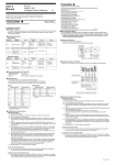
9. Specifications
■ Source/Measurement Functions
Accuracy: (% of set value or reading + °C, µV, or ), at 23 5°C
Accuracy
Range
Selection
TC
*1
Range of Source/Measure
Resolution
Source *3
K
-200.0 to +1372.0°C
E
-200.0 to +1000.0°C
J
-200.0 to +1200.0°C
T
-200.0 to +400.0°C
N
-200.0 to +1300.0°C
R
S
0 to 1768°C
Measurement *4
Remarks
0.05%+1°C
0.07%+1.5°C
-100°C or above
0.05%+2°C
0.07%+2°C
Below -100°C
0.05%+3°C
0.07%+3°C
Below 100°C
0.05%+2°C
0.07%+2°C
100°C or above
0.05%+4°C
0.07%+4°C
Below 1000°C
0.1°C
1°C
B
+600 to +1800°C
0.05%+3°C
0.07%+3°C
1000°C or above
L
-200.0 to +900.0°C
0.05%+0.5°C
0.07%+1.5°C
0°C or above
U
-200 to +400°C
0.05%+1°C
0.07%+2°C
Below 0°C
-10.00 to +110.00 mV
0.05%+30 V
0.05%+30 V
0 to 400 0.05%+0.2 0.05%+0.2 *5
0.05%+0.6°C
0.05%+0.6°C*5
100 mV
400 PT100 *2
-200.0 to +850.0°C
JPT100
-200.0 to +500.0°C
Measurement range:
0 to 110.00 mV
Excitation current
*6
0.1°C
0.1 V
0.1 0.1°C
Temperature coefficient: 1/10 of accuracy/°C
*1: According to JIS C 1602-1995 (Reference Thermo-electromotive Force Table). L and U are determined
according to the DIN standard.
*2: According to JIS C 1604-1997 (Reference Resistance Table)
International Practical Temperature Scale of 1968 (IPTS68) for PT100 reference resistance
IPTS68 for PT100 is -200 to +650°C.
*3: The TC generation accuracy does not include the RJ accuracy.
The sensor output accuracy must be taken into consideration when output compensation is determined
based on the RJ temperature (output compensation performed every 4 seconds).
*4: When it is calculated according to the Reference Thermo-electromotive Force Table, the TC measuring
accuracy includes the RJ accuracy (TC accuracy added).
The terminal temperature must be stable.
*5: Three-wire measurement
*6: Excitation current for generation: 0.5-2 mA; Excitation current for measurement: approximately 2 mA
When the excitation current is 0.1 mA, 0.05% + 1°C (0.4 ) is added, and the maximum input capacitance of
the device under calibration is 0.1 µF.
Four 1.5-V alkaline batteries (LR6, AA-size) or dedicated AC adapter
(sold separately)
Battery life:
Approximately 55 hours (when running on alkaline batteries)
Automatic Power Off: After a period of approximately 10 minutes with no operations
Generation Signal Level Setting:
By four sets of up and down keys
Response of generator: Approximately 20 ms (between the time when the specified current is
supplied and the time when the output value enters the accuracy range)
Loading conditions:
Less than 0.1 µF (DCV)
Measured-value indication updating intervals:
Approximately 1 second
Display:
7 segments LCD
Maximum allowable applied voltage:
42 V between each terminal and ground
Operating temperature and humidity range:
0 to 50°C, 20 to 80% R.H. (no condensation)
Storage temperature and humidity range:
-20 to 50°C, 90% R.H. or less (no condensation)
Dimension:
Approximately 192 (H) 92 (W) 42 (D) mm (excluding protrusions)
Weight:
Approximately 440 g
Accessories:
Lead cables (B9108MT) for measurement and generation
(one set, consisting of two black cables and one red cable)
Terminal adapter (B9108KF)
2 manuals
Optional accessories: Dedicated AC adapter
(A1020UP: AC100 V, A1022UP: AC120 V, B9108WB: AC 220-240 V)
Carrying case (B9108NK)
Rubber boot (93038)
Strap (97040)
Accessory case (B9108XA)
RJ sensor: reference junction compensation (B9108WA)
Safety standards:
EN61010-1 (only AC adapter B9108WB)
(A1020UP and A1022UP are excluded.)
EMC standards:
EN61326 ClassB
EN55011 ClassB Group1
EN61000-3-2
EN61000-3-3
Immunity:
EN61326
Performance criterion under immunity test environments: B
(self-returnable performance deterioration)
Test conditions of EMC and Immunity standards:
AC adapter (B9108WB), Lead cables (B9108MT) and RJ sensor
(B9108WA) are used.
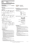
10. How to Use the Carrying Case and Rubber Boot
■ Carrying case (B9108NK)
The carrying case (B9108NK) may be used as follows:
(1) Undo the fasteners on the top
and sides of the case cover to
open it.
(2) With the fastener on the logoside of the case centered, lift the
cover and pivot it to the side and
under the case itself.
(3) Re-do the fasteners at the top
and sides of the cover.
Power supply:
Note: The fastener on the logo-side cannot be undone.
■ Rubber boot (93038)
■ Anti-skid pad
Anti-skid pad
(supplied)
The optional rubber boot provides
shock protection and can be used
with a strap.
Note: When using the instrument with a rubber boot, the anti-skid pad at the bottom is not
needed. When used without a rubber boot in a leaning position, the supplied anti-skid
pad should be used.
■ Specifications of the External RJ Sensor *3
Measuring range
-10 to +50°C
(Model: B9108WA)
Accuracy (when combined with the instrument)
18 28°C:
0.5°C
Other ranges: 1°C
Cord length: Approximately 1.5 m
Compensation using the built-in sensor is also possible by adjusting the setting of the internal DIP
switch on the instrument.
IM CA12E-02E <2>