1
5
4,755,852
duced copies. Steps n12 through n14 and n12’ through
6
n14’ may be deleted from the ?ow charts of FIGS. 2
white original document is used with the same exposure
data D will take upon an appropriate value.
and 3 if the user so desires.
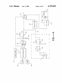
In FIG. 4 which is a circuit diagram of an exposure
control device for a copier according to another em
transmitted together with the exposure data D’ to the
subtractor circuit 59 in the case of automatic mode of
bodiment of the present invention, numeral 51 indicates
a microcomputer adapted to process data in units of 8
bits and numeral 52 generally indicates an input device
for the copier and includes a PRINT key and a TEST
The aforementioned document density data VA is
operation. The subtractor circuit 59 serves to modify
the exposure data D’ by the document density data VA
and transmits exposure data D" given by V0+Di—VA
to the copy lamp regulating circuit 58. Thus, VA be
key as explained above in connection with FIG. 1. The 0 comes greater where the original document to be cop
ied is brighter. This makes (V0+Di—V,4) smaller and
input data entered through these keys and/or buttons
the exposure becomes weaker, thereby accomplishing
are received by the microcomputer 51. The program by
the objective of automatic exposure. In the case of man
which the microcomputer 51 controls the operation of
ual mode of operation, on the other hand, the aforemen
the copier is already stored in ROM 19. RAM 18 is used
as working areas for various ?ags and counters when 15 tioned value D represents the level of exposure such
that exposure is uniquely determined if this value is set.
the control program is executed.
In the case of automatic exposure, the value of D serves
The microcomputer 51 computes exposure data D on
to shift the level of exposure as a whole and this value
the basis of the entries from the input device 52. The
changes when exposure sensitivity is set.
exposure data D is an 8-bit data and can be set in 256
A program according to one embodiment of the pres
steps from 0 to 255. The exposure data D calculated by
ent invention for the operation of the microcomputer 51
the microcomputer 51 is serially received by a digital
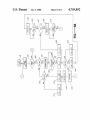
of FIG. 4 is shown by a ?ow chart in FIG. 6. With
to-analog converter 53 which converts the digital expo—
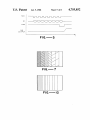
sure data D into an analog exposure data D. FIG. 2 is a
reference next to this flow chart, the microcomputer 51
lates the brightness of a copy lamp 62 through the phase
copying operation is resumed until it is completed (n35).
control of an AC power source 61 by triggering a triac
FIG. 7 shows schematically how a copy thus obtained
by such a test mode of operation may appear when
N=7. The user can determine the optimum exposure
sensitivity from such a result and set its value by operat
?rstly receives data from the input device 52 (n21). If it
time chart showing this serial transmission of exposure
25 is found that the key which has been operated is the
data D. With reference to FIG. 5, the microcomputer
TEST key (YES in n23), a test ?ag FT is set (n24). If the
51 transmits to the digital-to-analog converter 53 not
PRINT key is subsequently operated (YES in n22), the
only a clock pulse SCK but also the exposure data D as
original document to be copied is scanned (n26) because
8-bit serial data SI, and the digital-to-analog converter
the ?ag is in set condition (YES in n25). There is pro
53 latches the serial data SI for each rise of the clock
vided a counter C used as the indicator of exposure
pulse SCK. Right after the eighth serial data SI be
sensitivity which can be varied in a plurality of steps
comes effective, the microcomputer 51 transmits a
and when the time for starting exposure is reached
strobe pulse STB and the digital-to-analog converter 53
(YES in n27), the counter C is set to l which serves as
transmits the analog exposure data D at the rise of this
its initial value. Thereafter, the exposure data D corre
strobe pulse STB.
35 sponding to the current counter value C is computed
With reference again to FIG. 4, numeral 54 indicates
according to a prede?ned functional relationship f1
an operational ampli?er which receives the exposure
between D and C (n29), and the exposure value D thus
data D and transmits exposure data D’ given by V0+Di
computed is transmitted to the digital-to-analog con
where V0 is a lower limit value determined by a resistor
verter 53, thereby setting the brightness of the copy
55 and i is a constant adjustably determined by another
lamp 62 (n30). Next, the system waits until a predeter
resistor 56. Numeral 57 indicates an analog switch and
mined time period has elapsed (n31) to add 1 to the
serves to transmit the exposure data D’ by a signal from
counter C (n33) unless the counter value C has reached
the microcomputer 51 directly to a copy lamp regulat
a prede?ned maximum value N (NO in n32) and repeats
ing circuit 58 in the case of manual mode of operation
Steps n30 and n31. The photoreceptor of the copier is
and through a subtracter circuit 59 to the copy lamp 45 thereby automatically exposed'with N different levels
regulating circuit 58 in the case of automatic mode of
of exposure sensitivity. When the counter C reaches the
operation. The copy lamp regulating circuit 58 regu
maximum value N, the test ?ag FT is reset (n34) and the
60. The copy lamp regulating circuit 58 also serves to
safeguard against voltage variations of this power
source 61 such that the exposure can be maintained
always at a constant level.
Numeral 63 generally indicates a density detecting
circuit for detecting the density of an original document
to be copied. Numeral 64 indicates a photosensor for
detecting the intensity of the reflected light from the
original document. The photosensor 64 is adapted to
output a voltage proportional to the amount of light
received thereby. Numeral 65 indicates an operational
ampli?er which serves as a buffer and numeral 66 indi
ing a sensitivity setting key (YES in n36) to store the
selected exposure sensitivity A (n37).
If the PRINT key is operated in an ordinary mode of
operation other than the test mode (NO in n25), copy
ing is effected with the set exposure sensitivity A. In this
situation, exposure data D corresponding to the expo
sure sensitivity A is computed from the aforementioned
functional relationship f1 therebetween (n38) and trans
mitted to the digital-to-analog converter 53 (n39) and
cates another operational ampli?er which ampli?es the
output from the photosensor 64 through the operational
ampli?er 65 and thereby outputs document density data
ordinary copying is effected (n40).
when a black original document is used and when a
tured that a different sheet of copy paper is used for
According to the control program described above
by way of the flow chart shown in FIG. 6, a single sheet
VA. Numeral 67 indicates a resistor for adjusting the 65 of copy paper is exposed while the exposure sensitivity
ampli?cation of the operational ampli?er 66 such that
is sequentially changed in a stepwise fashion. Alterna
the difference in voltage applied to the copy lamp 62
tively, however the control program may be so struc