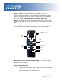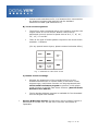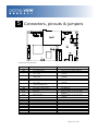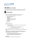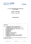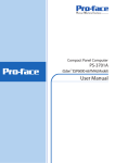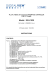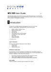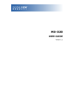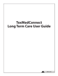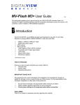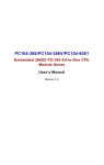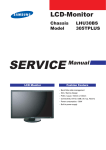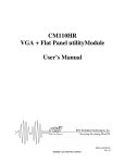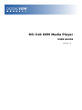
1
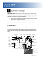
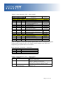
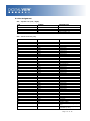
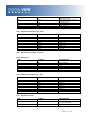
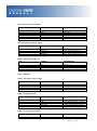
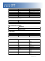
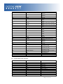
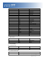
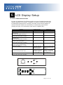
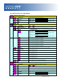
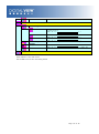
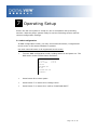
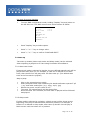
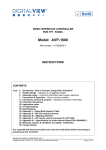
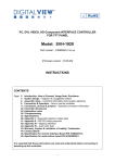
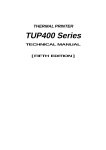
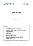
M3-310 OEM Media Player USER GUIDE Version 1.2 Revision History Amendment Date March 2009 April 2009 October 2009 Version V 1.0 V 1.1 V 1.2 Page 2 of 36 Table of Contents 1 Introduction ................................................................................ 4 2 System Design ............................................................................ 5 2.1 Familiarization ...................................................................... 5 3 Connection Overview ................................................................... 7 3.1 Prepare for connection ........................................................... 7 3.2 Basic connection for M3-310 ................................................... 7 4 System Notes ............................................................................. 9 5 Connectors, pinouts & jumpers ..................................................... 12 5.1 Jumpers setting ................................................................... 13 5.2 Pin Assignment .................................................................... 15 6 LCD Display Setup ...................................................................... 21 6.1 Use of OSD switch mount...................................................... 21 6.2 OSD Functions for LCD display ............................................... 22 7 Operating Setup ......................................................................... 24 7.1 OSD Configuration ............................................................... 24 7.2 Start up ............................................................................. 25 7.2.1 Start track mode .......................................................... 25 7.2.2 Sleep mode ................................................................. 25 7.3 Loop Playback ..................................................................... 26 8 Playback Operation ..................................................................... 27 8.1 Playback modes ................................................................... 27 8.1.1 Playlist mode ............................................................... 27 8.1.2 Simple play mode ........................................................ 27 8.2 Operating functions .............................................................. 28 8.3 Formatting Compact flash card .............................................. 29 8.4 Exporting Project and Playlist ................................................ 30 8.5 USB update......................................................................... 32 9 Dimension ................................................................................. 33 10 Specification ............................................................................ 34 Page 3 of 36 1 Introduction The M3-310 is an embedded video media player OEM board with a built in LCD interface. The board is ideally suited for fanless solid-state media player and LCD display products for market applications such as digital signage, retail promotion systems and information displays in places such as museums. This brief guide explains how to set up the M3-310 media player board. It is intended for system integrators looking to build a media player with an integrated LCD display. A few of the key features: Suitable for fanless system designs with CF card storage Supports a wide range of LCD panels Media support includes: o MPEG-1, MPEG-2, MPEG-4 (DIvX) o MPEG still o JPEG Dedicated button interface External communication and control through RS-232 (full protocol set available) USB update of media Range of outputs including: o Direct LCD panel connection o Support TFT (active matrix) LCD with LVDS and TTL single pixel interface of the following panel resolutions: 1600x1200 1366x768 1280x1024 1280x768 1024x768 800x600 800x480 640x480 USAGE NOTE Unless the M3-310 has been customized the media player functions will be the same as used in the Digital View media players: ViewStream 300 (VS-300) : A stand-alone media player M3-300 : A stand-alone media player (board) Note: Reference to these models and related documentation should provide a good basis for understanding the operation and capabilities of the M3-310 media player board. For details about custom options please contact Digital View. Page 4 of 36 2 System Design IMPORTANT NOTE: Whist the M3-310 does make it easy to build a media player based system it is intended for use by qualified system builders and integrators; the manufacturer accepts no liability for damage or injury caused by the use of this product. It is the responsibility of the system builder or integrator using the M3-310 and related parts to: Ensure that all necessary and appropriate safety measures are taken. Obtain relevant regulatory approvals. Check power settings to all component parts before connection. DISCLAIMER: There is no implied or expressed warranty regarding this material. 2.1 Familiarization The M3-310 media player board has a number of accessories, internal connectors headers, external type connectors and indicator lamps. Before any system design commences it is important to understand the purpose of all these and the system options they enable – please review the board itself together with the notes and relevant tables as detailed throughout this user guide: M3-310: 2 CF card 1 Switches and 3 Inverter socket Buttons connector (#9 - #16) 4 Controller 5 Backlight Status Status Status 22 RS-232 port 21 480p/720p 6 Reserved 7 USB connector JP16 LED1 LED2 JP15 1 JP4 8 Auxiliary power JA1 1 output JB6 20 Switches and Buttons connector (#1 - #8) 1 9 Alternative power VR1 10 Backlight inverter JB1 JB2 JB3 19 Reserved out 1 1 3V3 5V JB5 JP1 JP5 JA3 18 IR connector 11 OSD Control 17 Serial port (For panel) JP2 JP3 JP6 JP7 12 Power input (DC 12V) 13 Speaker out (L/R) 14 Alternative line out 15 TTL panel connector 16 LVDS panel connector Page 5 of 36 Summary: 1. 2. 3. 4. 5. 6. 7. 8. 9. 10. 11. Switches and buttons (9 – 16 button) Compact Flash card slot Inverter status LED1 - Controller status LED2 - Backlight status Reserved USB connector Auxiliary power output Alternative power out Backlight inverter OSD control 12. 13. 14. 15. 16. 17. 18. 19. 20. 21. 22. Power input (DC +12V) Speaker out (L/R) Alternative line out TTL panel connector LVDS panel connector Serial port (for panel control) IR sensor connector Reserved Switches and buttons (1 – 8 button) Output resolution (480/720p) RS-232 port For detailed pin-outs on all connectors see the tables in Section 5 below Page 6 of 36 3 Connection Overview CAUTION: Never connect or disconnect parts of the system when the system is powered up as this may cause serious damage. 3.1 Prepare for connection Connection and usage are straightforward. However, during assembly, care needs to be taken regarding the following: Ensure parts, especially power and signal cables, match the system. If you are making your own cables & connectors refer carefully to the video monitor specifications and the “Connectors, Pin outs & Jumpers” section in this user guide to ensure the correct pin-to-pin wiring. Ensure cables have been correctly connected and that connections are secure. Screws and fasteners need to be secure, consider using locking glue if appropriate. Switches and jumpers are set correctly. The output signal is compatible with display equipment. Legal & safety requirements have been met with particular attention to the likely operating environment. Although the M3-310 is designed to be fanless in normal conditions some installations and environments may require additional cooling. 3.2 Basic connection for M3-310 The following summarizes a simple connection: Connect the inverter (if it is not built-in the panel) to the CCFT lead connector(s) on the panel. Plug the inverter cable to CNB1 and CNA1.(if necessary) on the M3-310. Plug another end to the connector on the inverter. Note: Different inverter models require different cables and different pin assignment. Make sure correct cable pin out to match inverter. Using wrong cable pin out may damage the inverter. Plug the panel signal cable direct to CN2 (if TTL panel is used) or J3 (if LVDS panel is used) on the M3-310. Plug the other end of cables on the LCD panel connector. Page 7 of 36 CAUTION: Before connecting power ensure all parts are suitably insulated and there is no risk of short circuit or electrocution. Connect the power supply (DC 12V @ 1.2A minimum. - ensure correct polarity) to the M3-310 power input (PP1). Plug the OSD switch mount cable (p/n:420680260-3) to CNC1 on the M3-310 and another to the OSD switch mount. (P/N:416100520-3) For “Auto play with Power On” , short the pin1-2 on JP6 Ensure there is a CF card installed with compatible media loaded. If the optional buttons are being used connect them to CN6 and CN3 Page 8 of 36 4 System Notes The following outlines various issues related to the M3-310 and making a complete system: LED1/LED2 - The power/status LED indicator shows the following status of Panel: Controller LED status (LED1): Panel State No signal & backlight off No signal & backlight on With signal & backlight on LED color RED ORANGE GREEN Backlight LED status (LED2): Panel State Backlight fault Backlight normal LED color RED GREEN NOTE: This status is only available when CNB2 is proper connected and the panel is support the backlight status function. RS-232 port – This port supports RS-232 communications for control. The baud rate must be set to (9600, n,8,1) and record suffix is set to CR (0DH). USB – Plug an USB extension cable (P/N:426894600-3). Use a USB flash drive for content update without removing the CF card. The M3310 will reset the power when a USB flash drive is inserted or removed from the USB connector. (For the details of USB content update, please refer to the Application note.) Audio output – This provides speaker out and line out connection. Master volume is controlled through OSD with buttons connecting to CN6. For connection, plug a stereo speaker (P/N 230800301) with stereo cable (P/N 426680900-3) to the connector CN1. If for line out connection, connect an audio line out cable (P/N 426450300-3) to CN9. Volume control – To control the loudness of internal speaker, a 47K Volume Rotary (VR) can be used. Plug the VR extension cable (P/N:426890510-3) on to the jumper VR1. Jumpers & Inverter & Panel voltage – pay special attention to the settings of JA3, JB2 & JB3. The JB2 & JB3 are used for inverter control (read inverter specification and information on the jumper table to define the correct settings). The JA3 is used for panel voltage input (read panel specification and information on the jumper table to define the correct settings). Page 9 of 36 Power supply - Plug the DC 12V power (ensure correct + & orientation) in to the connector PP1. The Digital View mating power cable is (P/N 426013800-3), 160mm. Please read the jumper table in Section 5 to define the correct settings. Otherwise it may break down the panel. (Note: Maximum current output to panel: 2A) Power on - Switch on the M3-310 board and panel by using the OSD switch mount (P/N 416100520-3) or short Pin1-2 at JP6 for “Auto power On”. Infra-red (IR) - Supports IR control with DV remote control handset (P/N:559000104-3). The IR sensor and cable kit (P/N:446010401-3) are required. The IR control functions are shown as below. ATTENTION + Key “3” (IR enable/disable) Direct Track # Access Mute OSD on/off Repeat Stop Pause Previous track Play Next track Volume Up Volume Down Buttons and Touch screen (segment type) – A number of related accessories are available providing enhanced functionality such as user buttons and touch screen. A) Mechanical buttons Standard MV-switchmount (P/N:416101300-3) for 1-8 buttons when connected to the button connector CN6 via the standard switchmount cable (P/N:426451100-3). Page 10 of 36 Custom made switchmount for 1-16 buttons when connected to the buttons connector CN6 and CN3 via the standard switchmount cable (P/N:426451100-3) B) Touch screen segments The M3-310 when connected with a LCD interface controller can output videos on to LCD screen. Button control can be performed via touch screen for panel sizes of 6.4”, 7”, 8”, 10”, 12”, 15”, 17” and 20” There is one type of button pattern layouts on the touch screen available: 8 buttons (For any special button layout, please contact local sales office.) Fig. 1 8-buttons for LCD touch screen C) Button function settings Whether the buttons are of the mechanical type (on the standard switchmount or custom made) or the touch screen segment type, each button function can be programmed with the DV Studio Software program to perform a VCD player mode function or specific track select function. (See DV Studio Software user manual). The DV Studio Software program is available for free download from the Digital View website. Service & Warranty Forfeit: The warranty will be invalid if rework is performed on the M3-310. The M3-310 is not user serviceable or repairable. Page 11 of 36 5 Connectors, pinouts & jumpers JP16 LED1 LED2 JP15 1 JP4 JA1 JB6 1 1 JB1 JB2 JB3 VR1 1 1 3V3 5V JB5 JP1 JP5 JA3 JP2 JP3 JP6 JP7 The various connectors are: Ref CN1 CN2 CN3 CN8 CN9 CN10 CN11 Purpose Speaker out (L/R) connector TTL panel signal Switches and buttons connector (#9 - #16) Watchdog programmer connector (Reserved) RS-232 port Switches and buttons connector (#1 - #8) Resolution selector (640x480/1280x720) Serial control Alternative audio output Alternative power out connector Reserved CN12 USB connector CNA1 CNB1 CNB2 CNC1 PP1 IR1 VR1 J3 J6 J7 Auxiliary power output Backlight inverter Backlight status OSD controls Power input IR sensor connector External volume control LVDS panel signal CF card connector USB connector CN4 CN5 CN6 CN7 Description JST B4B-XH-A Hirose 40-pin, DF20G-40DP-1V Hirose 1.25mm, 9-pin, DF13-9P1.25DSA Hirose 1.25mm, 6-pin, DF13-6P1.25DSA JST B6B-XH-A Hirose 1.25mm, 9-pin, DF13-9P1.25DSA JST B2B-XH-A JST B6B-XH-A JST B4B-PH-K JS-1116-04WS Hirose 1.25mm, 6-pin, DF13-6P1.25DSA Hirose 1.25mm, 4-pin, DF13-4P1.25DSA JST B4B-XH-A JST B5B-XH-A JST B2B-XH-A JST B12B-XH-A Molex 43650-0200 JST B3B-XH-A 3x2 header (2.54mm pitch) Hirose DF13-40DP-1.25DSA CF-CARD, 25x2Ppin 3M CF-II socket JST B4B-ZR Page 12 of 36 5.1 Jumpers setting Ref JA1 JA3 Purpose For internal testing Panel power voltage select JB1 Backlight brightness voltage range JB2 Backlight inverter on/off control – signal level JB3 Backlight inverter on/off control – polarity JB5 Backlight control type selection JB6 Backlight status JP1 Reserved JP2 JP3 JP4 Panel selection Panel selection Detect the watchdog pulse JP5 JP6 Panel selection Input power control JP7 Panel selection * Factory default Note 1-3 & 2-4 closed, factory set, do not remove See panel voltage setting table 1 CAUTION: Incorrect setting will cause panel damage 1-2 closed = 3.3V max* 2-3 closed = 5V max 2-3 = On/Off control signal „High‟ = +5V* 1-2 = On/Off control signal „High‟ = +3.3V Open = On/Off control signal „High‟ = Open collector CAUTION: Incorrect setting can damage inverter. 1-2 = control signal „high‟ = CCFT ON* 2-3 = control signal „low‟ = CCFT ON 1-2 =VR/Digital switch mount control 3-4 =Reserved 5-6 =Reserved 1-2, 3-4 closed = Backlight status Low – Normal 1-3, 2-4 closed = Backlight status High – Normal Open = Backlight status not used Reserved for internal programming use (Always 1-2 closed) See table 3 below See table 3 below 1-2 closed =Off the detection* 1-2 opened=On the detection See table 2 below Short = External switch control Open = Switch mount control See table 4 below Table 1: Panel voltage setting Input voltage via PP1 Panel Voltage JA3 3.3V 3V3 closed 5V 5V closed Jumper on board 12VDC CAUTION: Incorrect setting can damage the panel & controller Page 13 of 36 Table 2: Panel selection (JP5) – Panel model 1-2 JP5 3-4 5-6 Opened Opened Opened Opened Opened Opened Closed Closed Opened Closed Opened Closed Opened Opened Opened Opened Opened Closed Opened Closed Opened Opened Opened Opened Opened Opened Opened Closed Closed Opened Opened Opened Closed Opened Opened Closed Closed Closed Opened Opened Closed Opened Description For WXGA panel Samsung LTA260W2-L01(1) AU M220EW01(1) NEC NL12880BC20-02D(1) Sharp LQ315T3LZ24(2) AU Optronics M156XW01 V0(2) For XGA panel AU M150XN07(1) LG LM150X08-A4(1) Sharp LQ150X1LGB1(2) Sharp LQ150X1LGN2A(2) For VGA panel LG LP104V2(1) Data Image FG080012DNCWAG0Z(1) AU Optronics G104VN01(1) Sharp LQ10D421(1) Others PrimeView PD104SL5(2) AU Optronics A201SN01(2) Samsung LTM170ET01(3) Samsung LTM190M2-L31(3) CPT CLAA102NA0ACW(4) Panel resolution 1366x768 1680x1050 1280x800 1366x768 1366x768 1024x768 1024x768 1024x768 1024x768 640x480 640x480 640x480 640x480 800x600 800x600 1280x1024 1440x900 1024x600 Note: In addition to the above panel support lists, we are on going to support various panel models for M3-310. Please contact Digital View offices for supporting your panel that are not listed. Panel selection (JP2 &JP3) - Resolution JP2 Closed Opened Opened Closed JP3 Opened Closed Opened Closed Description WXGA XGA VGA Others Table 4: Panel selection (JP7) – Panel timing: JA7 1-2 Function Panel pixel format 3-4 LVDS data mapping select 5-6 Selection of TTL / LVDS panel connection Description Closed : Single Pixel Opened : Double Pixel Closed : Mapping A (LVDS panel) Opened : Mapping B (LVDS panel) Please adjust to get the correct picture. See as Appendix II for details of mapping A and B. Closed : LVDS Opened : TTL Page 14 of 36 5.2 Pin Assignment CN1 – Speaker out (Left / Right) PIN SYMBOL DESCRIPTION 1 2 3 4 GND L GND R Ground Left speaker out Ground Right speaker out CN2 – Panel connector (TTL) PIN SYMBOL DESCRIPTION 1 2 3 4 5 6 7 8 9 10 11 12 13 14 15 16 17 18 19 20 21 22 23 24 25 26 27 28 29 30 31 32 33 34 35 36 37 38 39 40 41 42 43 GND GND NC NC RA0 RA1 RA2 RA3 RA4 RA5 RA6 RA7 GND GND NC NC GA0 GA1 GA2 GA3 GA4 GA5 GA6 GA7 GND GND NC NC BA0 BA1 BA2 BA3 BA4 BA5 BA6 BA7 GND GND VS CLK HS DE PWR 44 VLCD Ground Ground No connection No connection Data bit R0 Data bit R1 Data bit R2 Data bit R3 Data bit R4 Data bit R5 Data bit R6 Data bit R7 Ground Ground No connection No connection Data bit G0 Data bit G1 Data bit G2 Data bit G3 Data bit G4 Data bit G5 Data bit G6 Data bit G7 Ground Ground No connection No connection Data bit B0 Data bit B1 Data bit B2 Data bit B3 Data bit B4 Data bit B5 Data bit B6 Data bit B7 Ground Ground Vertical sync Dot clock Horizontal sync Display enable Power down control signal (5v TTL) Panel power supply (3,3V/5V) (selected by JA3 ) Page 15 of 36 45 VLCD 46 VLCD 47 48 49 50 NC NC NC NC Panel power supply (3,3V/5V) (selected by JA3) Panel power supply (3,3V/5V) (selected by JA3) No connection No connection No connection No connection CN3 – Switches and buttons (#9 - #16) PIN SYMBOL DESCRIPTION 1 2 3 4 5 6 7 8 9 SW9 SW10 SW11 SW12 SW13 SW14 SW15 SW16 GND Button 9 Button 10 Button 11 Button 12 Button 13 Button 14 Button 15 Button 16 Ground CN4 – Watchdog programmer connector CN5 – RS-232 port PIN SYMBOL DESCRIPTION 1 2 3 4 5 6 NC NC 5V Tx GND Rx No connection No connection +5V Tx Data GND Rx Data CN6 – Switches and buttons (#1 - #8) PIN SYMBOL DESCRIPTION 1 2 3 4 5 6 7 8 9 SW1 SW2 SW3 SW4 SW5 SW6 SW7 SW8 GND Button 1 Button 2 Button 3 Button 4 Button 5 Button 6 Button 7 Button 8 Ground PIN SYMBOL DESCRIPTION 1 SYSTEM 2 GND 1-2 close: 1280x720 1-2 open: 640x480 Ground CN7 – Resolution selector Page 16 of 36 CN8 – Serial control (for Panel) PIN SYMBOL DESCRIPTION 1 2 3 4 5 6 SDATA SCLK Vcc TxD GND RxD Reserved Reserved +5V Tx Data GND Rx Data CN9 - Alternative speaker output PIN SYMBOL DESCRIPTION 1 2 3 4 GND AUDIO_L GND AUDIO_R Ground Audio left channel output Ground Audio right channel output PIN SYMBOL DESCRIPTION 1 2 3 4 VCC GND GND +12V +5V out Ground Ground +12V out CN10 - Alternative power out CN11 – Reserved CNA1 - Alternative power output PIN SYMBOL DESCRIPTION 1 2 3 4 AUX POWER GND GND AUX 5V +12V DC Ground Ground +5V DC CNB1 - Backlight inverter PIN SYMBOL DESCRIPTION 1 2 3 4 5 GND VBKL BLCTRL BVR_WIP BVR_A Ground Backlight Backlight Backlight Backlight power supply, +12VDC On/Off control signal brightness VR pin WIP brightness VR pin A CNC1 - Function control switch PIN SYMBOL DESCRIPTION 1 PSWIN Power button A Page 17 of 36 2 3 4 5 SW_ON BVR_A BVR_WIP BVR_B 6 7 8 9 10 11 12 GND MENU -/LEFT +/RIGHT SEL_DN SEL_UP NC Power button B Backlight Brightness VR pin A Backlight Brightness R pin WIP Backlight Brightness VR pin B (470 ohm resistor to +5V Vcc) Ground OSD menu OSD -/Left OSD +/Right OSD Select down OSD Select up No connection LED1 - Controller status LED connector PIN DESCRIPTION 1 2 3 Green LED pin (anode) LED pin common (cathode) Red LED pin (anode) LED2 - Backlight status LED connector PIN DESCRIPTION 1 2 3 Green LED pin (anode) LED pin common (cathode) Red LED pin (anode) IR1 - IR connector PIN SYMBOL DESCRIPTION 1 2 3 GND STDBY_VCC IR DATA Ground Stand by voltage IR data PIN SYMBOL DESCRIPTION 1 TXA0+ 2 TXA0- 3 TXA1+ 4 TXA1- 5 6 7 NC NC TXA2+ 8 TXA2- 9 TXA3+ 10 TXA3- 11 GND Positive differential LVDS data bit A0 Negative differential LVDS data bit A0 Positive differential LVDS data bit A1 Negative differential LVDS data bit A1 No connection No connection Positive differential LVDS data bit A2 Negative differential LVDS data bit A2 Positive differential LVDS data bit A3 Negative differential LVDS data bit A3 Ground J3 - Panel connector (LVDS) Page 18 of 36 12 13 GND TXAC+ 14 TXAC- 15 16 17 GND GND TXB0+ 18 TXB0- 19 TXB1+ 20 TXB1- 21 22 23 NC NC TXB2+ 24 TXB2- 25 TXB3+ 26 TXB3- 27 28 29 GND GND TXBC+ 30 TXBC- 31 32 33 GND GND VDD (3,3V/5V) 34 VDD (3,3V/5V) 35 VDD (3,3V/5V) 36 VDD (3,3V/5V) 37 38 39 40 NC NC NC NC Ground Positive LVDS clock for A channel Negative LVDS clock for A channel Ground Ground Positive differential LVDS data bit B0 Negative differential LVDS data bit B0 Positive differential LVDS data bit B1 Negative differential LVDS data bit B1 No connection No connection Positive differential LVDS data bit B2 Negative differential LVDS data bit B2 Positive differential LVDS data bit B3 Negative differential LVDS data bit B3 Ground Ground Positive LVDS clock for B channel Negative LVDS clock for B channel Ground Ground Panel power supply (3,3V/5V) (selected by JA3) Panel power supply (3,3V/5V) (selected by JA3) Panel power supply (3,3V/5V) (selected by JA3) Panel power supply (3,3V/5V) (selected by JA3) No connection No connection No connection No connection J6 – Compact Flash card connector PIN SYMBOL DESCRIPTION 1 2 3 4 5 6 7 8 9 10 11 12 13 GND D3 D4 D5 D6 D7 /CE1 GND GND GND GND GND VCC Ground Data bit 3 Data bit 4 Data bit 5 Data bit 6 Data bit 7 Card enable 1 Ground Ground Ground Ground Ground +5V Page 19 of 36 14 15 16 17 18 19 20 21 22 23 24 25 26 27 28 29 30 31 32 33 34 35 36 37 38 39 40 41 42 43 44 45 46 47 48 49 50 GND GND GND GND A2 A1 A0 D0 D1 D2 IOCS16 /CD2 /CD1 D11 D12 D13 D14 D15 /CE2 GND /RD /WR /WE IRQ VCC /CSEL NC RESET IORDY NC NC /DASP /PDIAG D8 D9 D10 GND Ground Ground Ground Ground Address bit 2 Address bit 1 Address bit 0 Data bit B3 Data bit B4 Data bit B5 IOCS16 Card detect pin 2 Card detect pin 1 No connection No connection No connection No connection No connection Card enable 2 Ground Memory read strobe Memory write strobe No connection Interrupt request +5V Chip SEL No connection System reset IO Ready No connection No connection DASP PDIAG No connection No connection No connection Ground PIN SYMBOL DESCRIPTION 1 2 3 4 UVCC DD+ GND USB - VCC -VE USB Data +VE USB Data Ground PIN SYMBOL DESCRIPTION 1 2 +12_CENTER GND +12V DC in center pin Ground J7 - USB connector J8 - M3-310 debugger PP1 - Main power input VR1 – External volume control PIN DESCRIPTION 1-3, 2-4 Close (Factory default) Open (for connection with 47K VR ext. cable (p/n:426890500-3)) Page 20 of 36 6 LCD Display Setup 6.1 Use of OSD switch mount By way of explanation the following refers to a set of sample buttons that may be obtained as an option. In addition to power on/off and connection for backlight brightness the controller provides an On Screen Display of certain functions which are controlled by 5 momentary type buttons (analog VR type) or 8 momentary type buttons (digital type): Controls On/Off – turns controller board power on Brightness – controls backlight brightness Menu – turns OSD menu On or Off (it will auto time off) (Function with signal input only) Select – Select function / Confirm (Works under OSD menu on state) Move up to select individual RGB color level OSD page (Works under OSD menu on state) + – increase the setting / moves the selector to the next function (Works under OSD menu on state) - - decrease the setting / moves the selector to the previous function (Works under OSD menu on state) Load factory default Lock OSD menu (Function with signal input only) Switch to next input source (Works under OSD menu off state) Analog VR type VR toggle switch Rotary VR Menu button Digital type On/Off button Brightness +/- buttons Menu button SEL DN SEL DN SEL UP SEL UP + + - - Press and hold SEL DN botton to power on the controller Press and hold MENU button for 15 seconds to enable / disable lock of the OSD menu + Press and hold SEL DN botton to power on the controller Press and hold MENU button for 15 seconds to enable / disable lock of the OSD menu + SEL UP - + M en u O N /O ff/B rig htn e ss SEL DN An a lo g VR typ e Dig ita l typ e Page 21 of 36 6.2 OSD Functions for LCD display Brightness and Contrast Brightness Contrast Exit Increase/decrease brightness level. Press – or + (steps Increase/decrease panel contrast level. Press – or + (stepsthe OSD menu and save the settings Exit + ) Total : 256 + ) Total : 192 Color Auto RGB Calibration# Color Temperature Yes No (See appendix IV) (Adjust the warmness of the image displayed. The temperature the image looks like. The lower temperature Adjustcoolest red color level warmest image looks like.) Press – or + (+) Total Adjust green color level Press – or + (+) Total steps Adjust blue color level Press – or + (+) Total steps Set the color temperature to 4200K Press SEL UP/DN button to select item Set the color temperature to 5000K higher the :128 steps : 128 : 128 Set the color temperature to 6500K Set the color temperature to 7500K Set the color temperature to 9300K Gamma adjustment Adjust Gamma settings (0.4 / 0.6 / 1.0 / 1.6 / 2.2) Select Gamma to 0.4 Select Gamma to 0.6 Select Gamma to 1.0 Select Gamma to 1.6 Select Gamma to 2.2 Exit Exit the OSD menu and save the settings Autosetup Auto adjust the positions, phase, frequency Frequency Yes No Adjust the image horizontal size Phase Fine tune the data sampling position (adjust image quality) Image Horizontal Position Image Vertical Position Use +/- to move the image horizontally Press – or + (Use +/- to move the image vertically Press – or + (- Position +) +) Page 22 of 36 Exit Exit the OSD menu Utilities OSD setting OSD Timeout : 0 / 10 / 20 / 30 / 40 / 50 / 60 seconds (Always on when set to 0) Press – or + (+) Load Factory Default Sharpness Exit OSD menu horizontal position Press – or + (+) OSD menu vertical position Press – or + (+) Initialize the setting stored in non-volatile memory Adjust sharpness level Press – or + (steps Exit the OSD menu + ) Total : 49 Exit the OSD menu Items marked have sub menus. Exit the OSD menu to save the setting chosen Page 23 of 36 7 Operating Setup Ensure the M3-310 system is ready for use in accordance with preceding sections. With the player system ready for use the following section outlines various configuration settings. 7.1 OSD Configuration In OSD configuration mode, you may need external buttons, 8-segmented touch screen or IR remote handset to operate. Use with external button or 8-segmented touch screen To enter OSD configuration mode, holding button 8 and power on. The OSD menu screen will be shown as follow: VOLUME 08 Y M D 2009 . 09 . 14 MON V1. 19. 00 H M S 21 : 00 : 12 ID NO: 0000 DATA LOGGING: OFF OSD: ON JPEG TRANS TYPE: OFF SAVE AND EXI T Press button 8 to select option. Press button 7 or button 6 for change value. Press button 7 or button 6 to confirm “SAVE AND EXIT”. Page 24 of 36 Use with IR remote handset To enter OSD configuration mode, holding “Display” key and power on the M3-300 unit. The OSD menu screen will be shown as follow: VOLUME 08 Y M D 2009 . 09 . 14 MON V1. 19. 00 H M S 21 : 00 : 12 ID NO: 0000 DATA LOGGING: OFF OSD: ON JPEG TRANS TYPE: OFF SAVE AND EXI T Press “Display” key to select option. Press “+” or “-” key to change value. Press “+” or “-” key to confirm “SAVE AND EXIT”. 7.2 Start up Two start-up modes (Start track mode and Sleep mode) can be selected when exporting a playlist to CF Card using DV Studio Plus software. 7.2.1 Start track mode If start track mode is selected in playlist, the pre-defined started track will be played first after boot-up. For example, if track #5 is defined as the start track, then the M3-310 will play track #5 after start up. (The default start track is the first track in playlist) Step by step: Plug in the external power supply Insert Compact Flash Card containing DV Studio Software exported “.pll / .prj” and other media files. (e.g. .mpg, .mp3, .jpg) Switch the power 'on/off' switch to 'on'. The track #5 (started track) will be played first. Once the track #5 is finished, the first track in playlist will be followed and played. 7.2.2 Sleep mode If sleep mode is selected in a playlist, a blank screen will be shown at the beginning until the pre-defined button has been pressed. For example, if button# 3 is defined in sleep mode, after boot-up the M3-310 will play a blank screen until the button #3 is pressed. Page 25 of 36 Step by step: Plug in the external power supply Insert CompactFlash Card containing DV Studio Software exported “.pll / .prj” and other media files. (e.g. .mpg, .mp3, .jpg) Switch the power 'on/off' switch to 'on'. Press 'button #3'. The first track will be played. Note: Special specific track playback activated by an assigned button can also be performed in sleep mode - contact Digital View for details. 7.3 Loop Playback The M3-310 will play in auto-loop play mode, so long as none of the function buttons are pressed. (NOTE: Loop playback is the standard playback setting of the M3-310 but the track playback sequence can be changed as required: contact local sales office.) Page 26 of 36 8 Playback Operation 8.1 Playback modes There are two playback modes in M3-310 – “Playlist mode” and “Simple play mode”. 8.1.1 Playlist mode When operating in playlist mode, both the project file (*.prj) and the playlist file (*.pll) must be present on the Compact Flash card. These are used to control the sequence for all video tracks. The project and playlist file are created using the Digital View DV Studio Plus software which is available for download from the Digital View website. Using this software, you can set simple sequences or complex sequences including “jump track“ or “next track” actions. DV Studio can also program buttons with different functions such as “play”, “stop”, “pause”, “mute”, “previous”, “next” and “volume”. 8.1.2 Simple play mode In simple play mode, the user just copies all video files (.mpg/.avi/.mov) or JPEG files (.jpg) onto the CF card in a folder called Media. The M3-310 will play these files in alphanumeric sequence. For JPEG files, the play time can be set by the last digit of the filename. (For example: APPLE5.jpg, where “5” means the track will be displayed for 5 seconds.) Note: Do not use the same filename for both MPEG and JPEG. Note: (1) Make sure all capital letters in filename defined in playlist are consistent with the filename on the CF card. All filenames should be in 8.3 format (i.e. xxxxxxxx.xxx) and avoid using any illegal characters like “~”, “_”, “-“, etc (2) All files (including project file and playlist file) must be placed under a folder named “Media” on Compact Flash card. For example: C o m p a c tF la s h c a r d C o m p a c tF la s h c a r d M E D IA M E D IA D E FA U LT. P R J L O O P.M P G D E FA U LT. P L L A P P L E 5 .M P G L O O P.M P G : : A PP LE .M P G : : P lay lis t m od e S im ple play m od e Page 27 of 36 8.2 Operating functions The following shows the default button operation in “Simple Play mode”. (This requires a button switch-mount or 8-segments touch screen connected.) PLAY (Button 1) Resumes playback of videos from track 1 after STOP has been pressed. Resumes playback of the track from the point that it has been set to PAUSE. Playback is reset back to the beginning of the specific track which is being played at the time the PLAY button is pressed. STOP (Button 2) When STOP is pressed the video stops playing and a blank screen is displayed. PAUSE (Button 3) When PAUSE is pressed playback will pause and the current image will remain screen. Press Pause again or PLAY to resume normal playback from the position where it was paused. REPEAT (Button 4) When REPEAT is pressed the current track loop back on itself continuously. To disable the repeat mode press REPEAT, PLAY, PREVIOUS TRACK or NEXT TRACK . When the track plays to the end it will playback the next track (and etc.) as normal. NEXT TRACK (Button 5) The NEXT TRACK function can be activated only when a track is already playing. When NEXT TRACK is pressed the current video stops playing and jumps directly to the start of the next track. VOLUME - (Button 6) Decreases audio output volume setting. VOLUME + (Button 7) Increases audio output volume setting. MUTE (Button 8) When MUTE is pressed, all the tracks will have no sound. Press MUTE again to resume the normal sound in all tracks. Note : The buttons can be re-defined by DV Studio Plus* software if operating in playlist mode. *DV Studio Plus software can be found and downloaded from www.digitalview.com Page 28 of 36 8.3 Formatting Compact flash card It is recommended that CF cards are re-formatted with FAT32 again before use. Formatting procedure for Windows: Double click the My Computer icon on your Windows desktop. Right-click the drive name of card reader. Click Format. The format dialog box appears. Click Start. Notes: ☞ CF cards should be formatted using FAT32 before first use. ☞ All media files on the CF must be in a folder name “media”. ☞ Filenames must be alpha-numeric characters only, not „~‟, „_‟, „-„, „!‟, „@‟, „^‟, etc. Page 29 of 36 8.4 Exporting Project and Playlist Use DV Studio Plus* software to export your project file (.prj) and playlist file (.pll). Make sure the CF card is formatted with FAT32 and the CF card reader is connected and the driver is well installed. The CF card reader is autodetected as the „Removable Disk” *DV Studio Plus software can be found and downloaded from www.digitalview.com Open DV Studio Plus software. Add a new playlist. Insert a media file to the playlist. Page 30 of 36 Set the play mode and button. Page 31 of 36 In the Project pull down menu, select Export and click Local Drives Click Enter the file path including a Media folder to export on CF card (e.g. E:\MEDIA ), then click OK Click Start to export. to select destination drive (i.e. Removable Disk). 8.5 USB update The M3-310 USB port provides the ability to connect a USB memory stick directly and to read and write data to and from the Compact Flash card using the automatic USB update capability. (Please refer to Application Note* for details) *Application Notes can be found and downloaded from www.digitalview.com Page 32 of 36 9 Dimension JP4 JP16 LED1 LED2 JP15 1 JA1 1 JB6 1 JB5 JP1 JP5 JB1 JB2 JB3 5V 3V3 1 1 VR1 JA3 JP2 JP3 JP6 JP7 The maximum thickness of the board is 38mm without add-on board (measured from bottom of PCB to top of components, including any underside components & leads). We recommend clearances of: 5mm from bottom of PCB - if mounting on a metal plate we also recommend a layer of suitable insulation material is added to the mounting plate surface. 10mm above the components 3~5mm around the edges Any of the holes shown above can be used for mounting the PCB, they are 3.2mm in diameter. CAUTION: Ensure adequate insulation is provided for all areas of the PCB with special attention to high voltage parts. (e.g. the inverter) Page 33 of 36 10 Specification Playable format MPEG-1 (.mpg) Encoding bit rate: 1.15Mbit/s MPEG-2 (.mpg) Encoding bit rate: 5Mbit/s MPEG-4 DivX (.avi) Encoding bit rate: 2Mbit/s JPEG (.jpg) Storage media Compact Flash memory card Recommended max. capacity: 16GB Panel output resolution 1280x720 or 640x480 Audio line out 3.2V p-p max. 5kohm Speaker out 1.5W @4ohm stereo Audio volume Controlled through OSD with switches attached or IR Playback functions Play / Stop / Pause / Repeat / Previous track / Next track / Volume / Mute Loop playback / Sequence play / Startup mode / Sleep mode Support Analog touch glass (4-wires) and ITO (8 or 16 segment type) touch glass Touch screen functions External I/O ports RS-232 (9600, N-8-1) USB (content upload) Infra-red (use with DV IR handset, P/N:559000104-3) Serial port (Panel status monitoring and control, 2400, n-8-1) Watchdog Support system reset Real time clock Battery-backup RTC Aux. power out +5V DC (fuse protection) +12V DC (fuse protection) Regulated DC 12V input (2.5mm center positive) Power requirement Power consumption 560mA @ 12V (no panel connection) Environmental Operating temperature Relative humidity Dimensions 147 (W) x 92 (D) x 18 (H) mm Weight (net) 135g : 0oC to 50oC : 5%-95% relative humidity (Non-condensing) Page 34 of 36 WARRANTY The products are warranted against defects in workmanship and material for a period of three (3) year from the date of purchase provided no modifications are made to it and it is operated under normal conditions and in compliance with the instruction manual. The warranty does not apply to: Product that has been installed incorrectly, this specifically includes but is not limited to cases where electrical short circuit is caused. Product that has been altered or repaired except by the manufacturer (or with the manufacturer‟s consent). Product that has subjected to misuse, accidents, abuse, negligence or unusual stress whether physical or electrical. Ordinary wear and tear. Except for the above express warranties, the manufacturer disclaims all warranties on products furnished hereunder, including all implied warranties of merchantability and fitness for a particular application or purpose. The stated express warranties are in lieu of all obligations or liabilities on the part of the manufacturer for damages, including but not limited to special, indirect consequential damages arising out of or in connection with the use of or performance of the products. CAUTION Whilst care has been taken to provide as much detail as possible for use of this product it cannot be relied upon as an exhaustive source of information. This product is for use by suitably qualified persons who understand the nature of the work they are doing and are able to take suitable precautions and design and produce a product that is safe and meets regulatory requirements. SAFETY INSTRUCTION Do not use this product near water, for example, near a bathtub, wash bowl, kitchen sink, laundry tub, in a wet basement or near a swimming pool. LIMITATION OF LIABILITY The manufacturer‟s liability for damages to customer or others resulting from the use of any product supplied hereunder shall in no event exceed the purchase price of said product. LICENSING REQUIREMENTS Depending on the features desired, customer/purchaser may be required to obtain a license with the relevant organizations. TRADEMARKS The following are trademarks of Digital View Ltd: Digital View M3-310 Page 35 of 36 CONTACT DETAILS USA: EUROPE: Digital View Inc. 18440 Technology Drive Building 130 Morgan Hill, CA 95037 Tel: (1) 408-782 7773 Sales: [email protected] Digital View Ltd 6 Marylebone Passage London W1W 8EX UK Tel: (44) (0)20 7631 2150 Sales: [email protected] ASIA: Fax: (1) 408-782 7883 Fax: (44) (0)20 7631 2156 Digital View Ltd 16th floor, Millennium City 3 370 Kwun Tong Road Kwun Tong Hong Kong Tel: (852) 2861 3615 Sales: [email protected] Specifications subject to change without notice Document No. 9172000-10 (October 2009) Fax: (852) 2520 2987 © Digital View Ltd 2009 Page 36 of 36