1
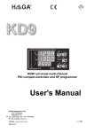
Ref
: VEX-T.ASTR-TCN.00349
Issue : 2
Rev. : 0
Date
: 06/02/2004
Page
: 7.5
The following figure presents the Wing Block diagram with different sections and strings.
WING
PANEL 2
PANEL 1
4 x 3 positive
power lines
Section 4
Section 3
Section 2
Section 1
4 x 3 negative
power lines
Grounding
Figure 7.2.1.1 : VEX Wing Block Diagram
The SA circuitry is as follows:
- Number of wings: 2
- Number of panel per wing: 2
- Numbers of sections per panel: 2
- Number of strings in parallel per section: 6
- Number of SCA's in series per string : 22
Two redundant bleed resistors, each 20 kOhms per panel, achieve short circuit protection.
Each string includes one blocking diode.
By design, each cell provides a by pass diode.