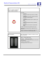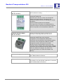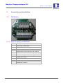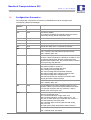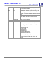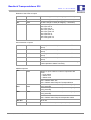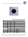
1
Baudisch.Transponderleser ID6
Manual
History:
Version
1.0
Date
Name
Change
27.06.2012
T. Eberhardt
Translation
Name
Division Initial Signature
T. Eberhardt
DEV
Approval latest version
Date
checked
27.06.2012
checked
PF
checked
VT
checked
User
checked
FE
20120627EB_HB_Transponderleser_ID6-EN.doc
1 / 27
Eb
Eb/27.06.2012
Baudisch.Transponderleser ID6
Version: 1.0 - As of: 27.06.2012
1.
Table of Content
1.
Table of Content ............................................................................................................................ 2
2.
General Information ....................................................................................................................... 3
2.1.
Symbols ......................................................................................................................................... 3
2.2.
Software History ............................................................................................................................ 3
2.3.
Hardware Versions ........................................................................................................................ 4
3.
Product Description ....................................................................................................................... 5
3.1.
General Information ....................................................................................................................... 5
3.2.
Abridgment .................................................................................................................................... 6
3.3.
Details ............................................................................................................................................ 8
3.4.
Accessories ................................................................................................................................. 11
4.
Connection and Installation ......................................................................................................... 15
4.1.
4.1.1.
4.1.2.
Connectors .................................................................................................................................. 15
ID6-JV-E, ID6-JV and ID6-Steel .................................................................................................. 15
ID6-RL ......................................................................................................................................... 16
4.2.
4.2.1.
4.2.2.
Solder bridges.............................................................................................................................. 16
ID6-JV-E, ID6-JV and ID6-Steel .................................................................................................. 17
ID6-RL ......................................................................................................................................... 17
4.3.
Front Panel Mounting type ID6-JV-E and ID6-JV........................................................................ 17
4.4.
4.4.1.
4.4.2.
4.4.3.
4.4.4.
4.4.5.
4.4.6.
4.4.7.
EasyLAN data bus ....................................................................................................................... 19
Basic Principle ............................................................................................................................. 19
Selection of Wires........................................................................................................................ 19
Length of Wires............................................................................................................................ 19
Wiring Architecture ...................................................................................................................... 19
Data Format................................................................................................................................. 19
Bus Subscriber Addressing ......................................................................................................... 20
File Transfer Process................................................................................................................... 20
5.
Software Logic ............................................................................................................................. 21
5.1.
5.1.1.
5.1.2.
Transponder ................................................................................................................................ 21
Functions ..................................................................................................................................... 21
Data Content................................................................................................................................ 22
5.2.
Teach-in Mode............................................................................................................................. 22
5.3.
Presence Logic ............................................................................................................................ 23
5.4.
Remote Control of the LEDs........................................................................................................ 23
5.5.
Input States.................................................................................................................................. 24
6.
Configuration Parameter ............................................................................................................. 25
20120627EB_HB_Transponderleser_ID6-EN.doc
2 / 27
Eb/27.06.2012
Baudisch.Transponderleser ID6
Version: 1.0 - As of: 27.06.2012
2.
General Information
2.1.
Symbols
Warning of dangerous electrical voltage.
This symbol points out important references, which must be followed to avoid injuries, as well as
damages and malfunctions of the product.
This symbol points out helpful references.
2.2.
Software History
Date
Version
Description / Function Expansion
20.12.2005
Initial Version.
30.05.2006
1.0
1.1
09.09.2006
1.2
RX-Uart Function improved.
24.03.2007
1.3
Add-on:
Parity Check EasyLAN added.
• Reset of A1 and A2 by Transponder 55558
• Separate parameter for time slot S2 and continuous
operation, new parameter 9, both adjustable in 0,5 sec
steps
• Editing of the access list by EasyLAN bus.
• Telegram repeats to target address adjustable by
parameter 0x0B.
24.04.2007
1.4
23.05.2007
1.5
New parameter 12, switching of the relays and the green
LED after adjusted time (in seconds) to use the ID6
without bus connection.
05.10.2007
1.6
Telegram extension C4-02-00-8x to identify the state of
the 4 LEDs.
05.12.2007
1.7
Switching to state presence 2, if parameter 12 is
activated.
11.04.2008
1.8
EMC test mode added, porting to ICC V7.X, EEPROM
mapping adapted.
25.04.2008
1.9
Digital inputs and reaction masks, EasyLAN bit masks
extended, status signal and transmit check added.
Calibration Byte in EEPROM changed from address 2 to
32.
Not relevant for the usability.
20120627EB_HB_Transponderleser_ID6-EN.doc
3 / 27
Eb/27.06.2012
Baudisch.Transponderleser ID6
Version: 1.0 - As of: 27.06.2012
07.05.2008
2.0
Reaction masks have priority to the internal LED switch
off.
08.05.2008
2.1
Test mode extended, start by special transponder chip.
03.06.2008
2.2
Bug fix: Handling of red LED, when transponder chip is
in detection range
22.01.2009
2.3
Bug fix: Internal Pull-ups for inputs (hardware option).
09.08.2010
2.4
EasyLAN bug fix (TX handler) added, new EEPROM
parameter for light switch in context with A1 and A2.
New parameter to handle state presence 1 and
presence 2 separately.
06.09.2010
2.5
Bit7 of parameter 10 (0x0A) has now a function:
Both green LEDs illuminated, if state presence 1 is
activated.
15.08.2011
2.3.
2.6
Handling of data packet and timer message in case of
receive of switch command at once.
Hardware Versions
Date
Version
Expansion
10.06.2010
0.1
Initial Version
23.09.2010
1.3
Improvement of the power supply (several modules
connected to one Door Module).
20120627EB_HB_Transponderleser_ID6-EN.doc
4 / 27
Eb/27.06.2012
Baudisch.Transponderleser ID6
Version: 1.0 - As of: 27.06.2012
3.
Product Description
3.1.
General Information
The vandalism protected transponder reader with self-sufficient key switch function and a
optional data bus connector for central configuration or function control was developed to detect
the presence of attendants in a hall of a prison.
Compared to well-established procedures based on PIN numbers, terminals or mechanical
keys, the transponder technology opens up important advantages.
• The detection of a transponder is contactless, so there is no wear.
• The reading operation is completed in a very short time and the key number is transmitted
securely.
• The needs no electricity, so you can carry it on your bunch of keys.
• In case of loss or damage a transponder can get prohibited and replaced by another one.
In condition of delivery each transponder is programmed to an individual key number. The
transponder communicates by a weak magnetic field with a few centimeter of range with the
reader.
If there is a transponder in the magnetic field, there is automatically a transmission of the data
to the reader. The reader detects the number and starts directly with programmed switching
functions or transmits the number together with it’s own code to a central unit.
• Up to 3 states and visualization with integrated LEDs.
• Visualization of presence in the hall.
• Cancellation of a prison cell call.
• Preparation of an officer’s alert (type ID6-JV) after activation 1 or timeout after activation 2.
• Compelled power-on of the cell electric lighting (type ID6-JV).
• Access control and door release with online link.
• Time posting “arriving – leaving – business trip” in conjunction with a data connection to a
central unit.
20120627EB_HB_Transponderleser_ID6-EN.doc
5 / 27
Eb/27.06.2012
Baudisch.Transponderleser ID6
Version: 1.0 - As of: 27.06.2012
3.2.
Abridgment
Item number
Name
Description
36-0147E
Transponder reader ID6-JV-E
Transponderleser ID6-JV-E
Basic version without sabotage
Basis-Version ohne Sabotageschutz
protection with covering panel in
mit Abdeckplatten aus eloxiertem
anodized aluminum.
Alu.
Transponder reader ID6-JV
Transponderleser ID6-JV
JVA version with sabotage contact
JVA-Version mit Sabotagekontakt und
and V2A covering. Shows status
V2A-Abdeckung. Zeigt die Zustände
presence 1 and 2.
Anwesenheit 1 und 2 an.
Transponder reader ID6-EA
Transponderleser ID6-EA
Transponder reader with 2 digital
Transponderleser mit 2 digitalen
inputs instead of an sabotage
Eingängen anstelle
switch. V2A covering, 2 relay
Sabotageschalter. V2A-Abdeckung, 2
outputs.
Relais-Ausgänge
36-0147
36-0185
20120627EB_HB_Transponderleser_ID6-EN.doc
6 / 27
Eb/27.06.2012
Baudisch.Transponderleser ID6
Version: 1.0 - As of: 27.06.2012
Item number
Name
Description
36-0183
Transponder reader ID6-RL
Transponderleser ID6-RL
Transponder reader for outdoor
Transponderleser für Anwendungen im
operations. 2 digital inputs, V2A
Außenbereich. 2 digitale Eingänge,
covering, 2 relay outputs.
2 Relais-Ausgänge, V2A-Abdeckung.
Transponderschalter ID6-Steel
Transponderschalter ID6-Steel
Vandal-protected transponder reader
Vandalismusgeschütztes
module with Baudisch.EasyLAN data
Transponder-Lesemodul mit
bus terminal.
Baudisch.EasyLAN Datenbusklemme
zur
33-1197
Anbindung an zentrale Komponenten
der Baudisch Zugangskontrolle oder
Zeiterfassung.
20120627EB_HB_Transponderleser_ID6-EN.doc
7 / 27
Eb/27.06.2012
Baudisch.Transponderleser ID6
Version: 1.0 - As of: 27.06.2012
3.3.
Details
Transponderleser ID6-JV-E
(Art.-Nr. 36-0147E)
Vandalism protected transponder reader with selfsufficient key switch function and optional data bus
connector for a central configuration or function check.
Built-in mounting in in-wall pattress box diameter 61mm.
Depth measured from rear side of the mounting panel
approx. 42mm.
Mounting panel with stainless steel cover approx.
80x80x6mm.
V2A safety screws.
Power supply 24VDC, 50mA.
1 Open Collector Output (80V, 15W, max. 250mA) for
electric lighting control.
2 multicolor LED indicators (red / green / yellow).
Acoustic function indicator available for all states if the
device like alert sound generation.
Safe detection of the transponder in a range up to
10mm.
Internal storage for 5000 keys or groups.
General erasure of all authorities, selective adding or
deleting of keys or groups by configuration transponder.
Individual erasure of lost transponders by configuration
transponder and master program unit.
Data bus interface for connection to central unit and
separate indicators.
Configuration with optional Windows software, also in
mounted state by data bus connection.
20120627EB_HB_Transponderleser_ID6-EN.doc
8 / 27
Eb/27.06.2012
Baudisch.Transponderleser ID6
Version: 1.0 - As of: 27.06.2012
Transponderleser ID6-JV
(Art.-Nr. 36-0147)
Vandalism protected transponder reader with selfsufficient key switch function and optional data bus
connector for a central configuration or function check.
Characteristics as ID6-JV-E, but addiotional features:
•
Electrical sabotage protection, acting if front panel is
removed.
•
Upper front panel consists of stainless steel V2A,
lower panel of anodized aluminum.
Due to the V2A front panel and the sabotage protection,
this device fulfills a higher safety standard than the base
version.
The software and configuration is the same as at ID6JV-E.
Transponderleser ID6-EA
(Art.-Nr. 36-0185)
Vandalism protected transponder reader with selfsufficient key switch function and optional data bus
connector for a central configuration or function check.
Characteristics as ID6-JV-E, but addiotional features:
•
Upper front panel consists of stainless steel V2A,
lower panel of anodized aluminum.
•
2 digital inputs, galvanic isolation by optocouplers.
Working from 12V to 24V DC.
The digital Inputs may generate several sounds
depending on the software configuration.
The state of the inputs can be sent to the central unit.
20120627EB_HB_Transponderleser_ID6-EN.doc
9 / 27
Eb/27.06.2012
Baudisch.Transponderleser ID6
Version: 1.0 - As of: 27.06.2012
Transponderleser ID6-RL
(Art.-Nr. 36-0183)
Vandalism protected transponder reader with selfsufficient key switch function and optional data bus
connector for a central configuration or function check.
Characteristics as ID6-JV-E, but addiotional features:
•
Upper front panel consists of stainless steel V2A,
lower panel of anodized aluminum.
•
2 digital inputs, galvanic isolation by optocouplers.
Working from 12V to 24V DC.
•
Coating of the printed circuit board to avoid
damages through high himidity.
•
Extended temperature range.
•
No speaker
This ID6 can be used in conjunction with a mast housing
as shown in the illustration.
Transponderschalter ID6-Steel
(Art.-Nr. 33-1197)
Transponder reader with Baudisch.EasyLAN data
interface for connection to a central unit for access
control and time recording.
Mounting in ModularSteel-System.
Power supply 24VDC, 50mA.
1 Open Collector Output (80V, 15W, max 250mA) for
electric lighting control.
2 multicolor LED indicators (red / green/ yellow).
Acoustic function indicator available for all states if the
device like alert sound generation.
Safe detection of the transponder in a range up to
10mm.
Internal storage for 5000 keys or groups.
The shown front panel has to be
ordered separately.
33-1176
V4A front panel for
ID6-Steel
General erasure of all authorities, selective adding or
deleting of keys or groups by configuration transponder.
Individual erasure of lost transponders by configuration
transponder and master program unit.
Data bus interface for connection to central unit and
separate indicators.
109,5 x 109,5 x 2mm Configuration with optional Windows software, also in
mounted state by data bus connection.
20120627EB_HB_Transponderleser_ID6-EN.doc
10 / 27
Eb/27.06.2012
Baudisch.Transponderleser ID6
Version: 1.0 - As of: 27.06.2012
3.4.
Accessories
Konfigurationskit ID6-JV
(Art.-Nr. 36-0147X)
The configuration kit ID6 is used to program the
transponder chips and consists of a PC software
(Windows 98, XP) and a programming device.
Scope of delivery:
•
Windows Software ID6-PROG with manual
(CD-ROM)
•
Programming device for connection to a PC
RS232 (COM1-COM4).
•
Wall power supply
•
5 transponder chips IC6-CP-RD (red
configuration transponder)
Scope of operation:
Detection and display of the data content of all
transponder chips (if there is no labeling)
Programming of the functions of configuration
transponders. Each configuration transponder can be
used for one of these functions:
- Deleting of a defined chip number (1 to 5000). The
number is programmed to the chip.
- Activating/deactivating of the teach-in mode of a
transponder reader.
- Deleting all of the 5000 authorities.
- Activation of all of the 5000 authorities.
- Reset of the Transponderlesers.
20120627EB_HB_Transponderleser_ID6-EN.doc
11 / 27
Eb/27.06.2012
Baudisch.Transponderleser ID6
Version: 1.0 - As of: 27.06.2012
Transponder Schlüsselanhänger
schwarz / blau / rot
(Art.-Nr. 31-0503, 31-0503R, 310503B)
Transponder keys for a contactless operation of the ID6.
Programmed with a safe 64 bit number, containing
system ID, customer ID and lock information.
Standard functional chain: A1 - A2 - Light - not active
Color: black
Programmed serial, Label with key number
•
Available colours:
o
31-0503
black / grey
o
31-0503R
red / grey
o
31-0503B
blue / grey
Each RFID product and it’s number is listed in a safe
data base in the factory. So it’s sure that each device is
individual programmed.
When ordering, you have to name one of these three
functions:
•
Standard use:
Triggering of a door release buzzer or access
permision.
•
Prison presence logic:
standard switching chain
A1 - A2 - Light - not active
•
Electrical lighting:
Switchs on the output as long as the transponder is
present in the detection range.
Measures of the transponder chip: Diameter 31mm,
max. 40mm
You can not order the transponder chips separately, you
always have to tell us a corresponding project.
20120627EB_HB_Transponderleser_ID6-EN.doc
12 / 27
Eb/27.06.2012
Baudisch.Transponderleser ID6
Version: 1.0 - As of: 27.06.2012
Transponder Schlüsselanhänger
rot
Special functions for transponder reader ID6
(Art.-Nr. 31-0503S, 31-0503P, 310503C, 31-0503F, 31-0503Z)
The designated function must be communicated with
each order:
•
31-0503S
Erasing of a spezific key number (1 to 5000)
•
31-0503P
Configuration transponder switchs on and off
the teach-in mode of the ID6
•
31-0503C
Locks all transponder chips of a system (1 bis
5000).
•
31-0503F
Unlocks all transponder chips (1 bis 5000).
•
31-0503Z
Resets the presence state of a transponder
reader
All items delivered as a key pendant in red / grey.
Measures of the transponder chip: Diameter 31mm,
max. 40mm
You can not order the transponder chips separately, you
always have to tell us a corresponding project.
Sektionalanzeige ID6-JDP
(Art.-Nr. 36-0177)
Indication of the state of up to 32 transponder reader
ID6 in LED technology. Labeling of numbers or names
with inlays possible.
State A1: illuminated green
State A2: flashing green (slow)
Time alert:
flashing green (fast)
Simple wiring of the transponder reader by 2 wire bus in
any architecture.
On-wall or in-wall mounting.
Power supply 24V DC, max. 700mA.
20120627EB_HB_Transponderleser_ID6-EN.doc
13 / 27
Eb/27.06.2012
Baudisch.Transponderleser ID6
Version: 1.0 - As of: 27.06.2012
ASB_2OutRelais
(Art.-Nr. 36-0113)
EasyLAN module comes with 2 relay outputs 48V / max.
10A for DIN rail mounting.
Double relay module to transfer the relays state to the
transponder reader ID6.
Reduction of the amount of wires: All transponder
reader can be connected by 2 wire bus in any
architecture (additional wires for sabotage and supply
necessary).
Useful for switching state remote indicator.
Two inputs for the connection of isolated switching
contacts to remote control the light switching output as
well as the speaker of the transponder reader ID6.
Datenbus-Interface RS232
(Art.-Nr. 36-0101)
RS232 converter with galvanic isolation for the
connection of the EasyLAN 2 wire bus to a PC
Remote monitoring of states and functions of up to 63
transponder reader ID6 per bus segment.
Configuration of the transponder reader ID6 in
conjunction with the Windows-Config-Software (WCS).
Connection of the transponder readers to a facility
management system with Open-Access-DDL.
Remote control of all switching functions, the LED
indicators and the speaker of the transponder reader in
conjunction with the Windows-Remote-Software (WRS).
There is a RS232 wire (length: 2m) and a kit for
mounting the device on a DIN rail included in the
delivery.
Windows-Config-Software (WCS)
Configuration of the transponder reader in conjunction
with a RS232 data bus interface.
Windows-Remote-Software (WRS) Remote control of all outputs, the LED indicators and
the speaker of the transponder reader ID6 in connection
with the RS232 data bus interface.
20120627EB_HB_Transponderleser_ID6-EN.doc
14 / 27
Eb/27.06.2012
Baudisch.Transponderleser ID6
Version: 1.0 - As of: 27.06.2012
4.
Connection and Installation
4.1.
Connectors
4.1.1. ID6-JV-E, ID6-JV and ID6-Steel
Number
Description
1
Power supply 24VDC/50mA
2
EasyLAN bus
3
0V (GND)
4
Open Collector Output (80V/15W, max. 250mA)
5
Isolated switching contact for sabotage
6
Isolated switching contact for sabotage
7
Isolated relay contact 1
8
Isolated relay contact 1
9
Isolated relay contact 2
10
Isolated relay contact 2
20120627EB_HB_Transponderleser_ID6-EN.doc
15 / 27
Eb/27.06.2012
Baudisch.Transponderleser ID6
Version: 1.0 - As of: 27.06.2012
4.1.2. ID6-RL
4.2.
Number
Description
1
Power supply 24VDC/50mA
2
EasyLAN bus
3
0V (GND)
4
Open Collector Output (80V/15W, max. 250mA)
5
Input 2 (0V)
6
Input 1 (0V)
7
Isolated relay contact 1
8
Isolated relay contact 1
9
Isolated relay contact 2
10
Isolated relay contact 2
Solder bridges
The devices is in an operable when delivered. If the relay contacts should be galvanic isolated
to each other, it is possible to configure by solder bridge.
Also there can be uses a 10kOhm resistor in the sabotage loop option, which is used instead of
the digital inputs E1 and E2.
To detect the state of the sabotage switch is not supported by the software until now.
20120627EB_HB_Transponderleser_ID6-EN.doc
16 / 27
Eb/27.06.2012
Baudisch.Transponderleser ID6
Version: 1.0 - As of: 27.06.2012
4.2.1. ID6-JV-E, ID6-JV and ID6-Steel
Solder
Bridge
closed
open
J1
Pin 8 is shared as a output of relay 1 default
and relay 2, that means connector 8 is
connected to 10.
J2
Sabotage loop resistance 0 Ohm
(default)
10kOhm
J3, J7
Sabotage is reported to controller
Sabotage state extern (default)
Solder
Bridge
closed
open
J1
Pin 8 is shared as a output of relay 1 Relay contacts isolated to each other
and relay 2, that means connector 8 is
connected to 10.
J6
Power supply of the inputs on
connector 10
4.2.2. ID6-RL
4.3.
Power supply of the inputs not connected
to the connector
Front Panel Mounting type ID6-JV-E and ID6-JV
When mounting the stainless steel front panel keep in mind to mount it straight and with no
application of a force until it seats solidly on the aluminum panel.
Do not push the stainless steel panel up, so the stud bolt will operate the switch securely.
!
Take care not to bend the switch when mounting the front panel.
Figure 1: The stud bolt of the front panel
operates the sabotage switch – the
sabotage loop is closed.
20120627EB_HB_Transponderleser_ID6-EN.doc
17 / 27
Eb/27.06.2012
Baudisch.Transponderleser ID6
Version: 1.0 - As of: 27.06.2012
Figure 2: The front panel is pushed
slanted above and inserted. The stud
bold is pressed closed to the sabotage
switch. Take care not to bend it, to avoid
malfunctions.
Figure 3: The stud bolt is inserted
correctly, the sabotage switch is operated
precise.
Figure 4: This picture shows a bent
switch and will lead into malfunction.
Adjust it as shown in figure 1.
20120627EB_HB_Transponderleser_ID6-EN.doc
18 / 27
Eb/27.06.2012
Baudisch.Transponderleser ID6
Version: 1.0 - As of: 27.06.2012
4.4.
EasyLAN data bus
EasyLAN was developed by Baudisch Electronic GmbH to connect electronic systems and
devices in an easy and safe way.
The design allows the use of long unshielded wires to connect the devices. Also it is resistant to
electrical damages.
4.4.1. Basic Principle
The bus conductor is connected to positive voltage (+12V) in one device. So it is on high
potential when in stand by mode.
All bus subscribers are able to pull the bus conductor down to ground potential by a tough
circuit to send data.
The bus conductor is connected to the micro controller highly resistive and EMC protected. So
the central processing unit is able to receive it’s own transmitted data and it’s able to compare it.
Also it’s possible to interpret data from other bus subscribers.
4.4.2. Selection of Wires
The easiest way to use EasyLAN is in 2 wire technology. In this case the wires are connected to
ground and bus signal. All bus subscribers need a separate power supply with galvanic isolation
(e.g. a wall wart).
Usually EasyLAN is used in 4 wire 2x2x0,6² technology. The second pair of wires allows to
bring the supply voltage (e.g. 12VDC) with the bus. So it is possible to power devices with a
small power consumption by the bus wire.
4.4.3. Length of Wires
The maximum length of wires depends on the used wires overall. Using a common shielded
communication cable 2x2x0,6 there is a possible length up to 2km.
High grade wires (e.g. green Instabus cable) are used for longer distances.
The EasyLAN bus allows a capacity of up to 100nF and a maximum loop impedance of 100
Ohm.
4.4.4. Wiring Architecture
It is not necessary to connect EasyLAN in star or loop architecture, it can be used any
architecture.
The most common way to install EasyLAN is to use one power supply for all ID6 readers. It is
not allowed to install a bus segment larger than the power supply range, because EasyLAN has
no galvanic isolation.
Installing the bus from floor to floor will lead to a connection of different ground potential and
leakage currents or ground loops.
4.4.5. Data Format
The data format of the EasyLAN data bus is compatible to many asynchronous serial interfaces.
EasyLAN can be converted via level converter to RS232 or RS422. There are corresponding
devices available providing galvanic isolation and function indicators. (e.g. EasyLAN PCInterface).
The data type is defined to 4800 Baud, 8 Bit, 2 Stop bit, Parity even
20120627EB_HB_Transponderleser_ID6-EN.doc
19 / 27
Eb/27.06.2012
Baudisch.Transponderleser ID6
Version: 1.0 - As of: 27.06.2012
4.4.6. Bus Subscriber Addressing
The EasyLAN technology achieves an aim to give the possibility to send a message to a
defined subscriber on the bus, if necessary. So each device needs it’s address to use it in the
telegrams.
One consequence is that the receiver confirms the reception. Any EasyLAN telegram includes a
target address and the address of the sender.
EasyLAN supports up to 64 logical bus addresses, shown in a data byte in the range from 40h
to 7Fh. When assigning the addresses, the subscribers with top priority have the lowest
address. It is important not to use an address several times.
4.4.7. File Transfer Process
Previous to send a data telegram by a device, the device checks for a idle bus for itself. The
duration of this check depends on the own address and will be restarted if the bus was busy.
Afterwards a telegram like this will be sent:
DST SRC STW LEN D0 .. Dn BCC CR
The receiver sends an acknowledgement telegram, that has to be received within 250ms:
DST SRC ACK
A receiver must give a receipt for a telegram with a correct syntax, independent if the data
content and the control command will lead into an activity.
If there is no acknowledgement received, the telegram is sent again. Attention: In the
acknowledge telegram DST means the address of the subscriber the telegram was sent from,
SRC stands for the sender.
20120627EB_HB_Transponderleser_ID6-EN.doc
20 / 27
Eb/27.06.2012
Baudisch.Transponderleser ID6
Version: 1.0 - As of: 27.06.2012
5.
Software Logic
5.1.
Transponder
5.1.1. Functions
The device discerns 8 different types of transponders with a different mode of operation.
Type
F-Identifier
Key Number
Description
N
0x20
1 to 65535
Transponder for normal access control without
further local logic.
L
0x80
1 to 5000
Toggles the electrical Light um (on <-> off)
A
0x81
1 to 5000
Changes the presence state (A):
A0 -> A1 -> A2 -> A0 and so on.
S
0x88
1 to 5000
Selective erase transponder
Switches the teach-in mode on or off and erases
by activating the teach-in mode the authority of
the key with a specific number. This is used to
delete a lost transponder chip.
P
0x88
55555
Configuration transponder (Program)
Switches the teach-in mode on or off. There are
no further functions.
C
0x88
55556
Erase transponder
Clears the memory by switching on or off the
teach-in mode and erases the authorities of all
keys (numbers 1 to 5000).
F
0x88
Formatting transponder:
55557
Switches on or off the teach-in mode and
activates the authority of all keys (1 to 5000).
R
0x88
Reset Transponder
55558
Restarts the software of the reader and clears
saved presence states A1 or A2.
T
0x88
Test mode activated.
55559
LEDs and relays toggle and sound plays
depending on test mode configuration (see
parameters).
20120627EB_HB_Transponderleser_ID6-EN.doc
21 / 27
Eb/27.06.2012
Baudisch.Transponderleser ID6
Version: 1.0 - As of: 27.06.2012
5.1.2. Data Content
The following data fields are programmed to the transponder and will be sent to the reader:
• Application ID
• Object ID
• Key number
• Date code creation
• Function detection
• Check sum process
5.2.
Application, use of the transponder, access control
Differentiation of the end user is made dependent to the
order.
2 Byte, adjustable from 1 to 65534
For the numbers 1 to 5000 there are can be authorities
for direct switch functions.
Day.Month.Year, each with two digits, for internal
application or interpretation by the host. There is no
influence to the switch authority.
Two-digit Hex, declares the function of the transponder.
For data safety during transfer.
Teach-in Mode
The teach-in mode allows to lock or unlock individual transponder chips in the authority list.
To do so the corresponding transponder must be in the detection range while the teach-in mode
is activated.
• Teach-in mode on/off by configuration transponder (P):
The tech-in mode is activated and disabled by using any transponder chip with function 0x88
(except chips for test mode) activated. When activating you will hear increasing tones, if
deactivated you will hear decreasing sounds. While this mode is active, the red LEDs will be
illuminated alternately (approx. 1 Hz).
• Transponder tech-in/erase:
The transponder will be activated in the active time period. So the state of clearance is
changed and the following new state is shown acoustically. Tech-in and erase will alternate
each time the chip is present. If the transponder is authorized, a positive signal will sound, if
the chip is locked, a negative signal will sound.
• You can only use teach transponder chips with function detection 0x80 (electrical lighting)
and 0x81 (presence).
• Time out:
The tech-in mode stops automatically 60 seconds after activation or last teach-in.
20120627EB_HB_Transponderleser_ID6-EN.doc
22 / 27
Eb/27.06.2012
Baudisch.Transponderleser ID6
Version: 1.0 - As of: 27.06.2012
5.3.
Presence Logic
To control the presence state logic, transponder chips must be programmed with the function
detection 0x81 and a key number from 1 to 5000.
• If there is a locked transponder detected, a negative tone is generated and there is no switch
operation.
• To reset the states A1 and A2 you have to use the same chip as you used to set the states.
• If there is an adjusted time out for state A1 (e.g. 10 seconds) the next transponder detection
will reset the chain to A0.
• If the reader is in state A0 and the transponder is in range longer than the adjusted time (e.g.
5 seconds) the reader is set to A0 when the chip is no longer present. With this function it is
possible to control the electrical lighting as long as the chip is in front of the reader.
• The indication of A1 is realized by the green LED with the Roman numeral 1, the indication
of A2 with both LEDs.
• In case A1 or A2 the output “light” is activated.
• The contact A1 is closed, as long as the reader is in state A1 (transponder detected once).
• The contact A2 is closed, as long as the reader is in state A2 (transponder detected twice).
5.4.
Remote Control of the LEDs
From software version 1.6 the 4 LEDs can be controlled by bus to indicate states in buildings.
For example: Alarm system activated/not activated, doors locked/unlocked and so on.
A bit mask, received by bus, defines the states with the 4 LEDs:
Bit 0:
Bit 1:
Bit 2:
Bit 3:
LED green at the top
LED red at the top
LED green at the bottom
LED red at the bottom
After starting the software (reset) the state is zero, the LEDs are off.
This indication is subordinated to internal functions of the reader. If there are other LED states
set by a switch function, the software will add them to the current state. So the remote indication
only works in stand-by state in the transmitted combination.
20120627EB_HB_Transponderleser_ID6-EN.doc
23 / 27
Eb/27.06.2012
Baudisch.Transponderleser ID6
Version: 1.0 - As of: 27.06.2012
5.5.
Input States
The two inputs can be used for several purposes. For example for indication of states (door
open/closed/locked etc.). The table below shows how to realize an optical and/or acoustical
indication depending on the inputs. The current state can be sent to a computer system if there
is a bus connection.
The state “on” signalizes the change from input active to inactive. The state “off” shows a
change from input inactive to active. An input is active if there is an electrical voltage present
and inactive if there is no voltage.
ú
Bit
Reaction
0
LED red 1 on
1
LED red 1 off
2
LED green 1 on
3
LED green 1 off
4
LED red 2 on
5
LED red 2 off
6
LED green 2 on
7
LED green 2 off
If there are two complementary bits set (e.g. red 1 on and red 1 off), the current state will toggle.
The number of available sounds starts the acoustic reaction. The range from 00h to 7Fh can
contain valid sound. Defined sounds (incl. FFh = 255d) are:
20120627EB_HB_Transponderleser_ID6-EN.doc
24 / 27
Eb/27.06.2012
Baudisch.Transponderleser ID6
Version: 1.0 - As of: 27.06.2012
6.
Configuration Parameter
The configuration of the device is stored in its EEPROM and can be changed by the
corresponding EasyLAN messages.
EEPROM
address
Default value
Description
00h
0x00
Reserved for CPU
01h
0x55
Load factory default
If this value is programmed unequal to 0x55, the device
will load the factory default values after reset.
02h
0x00
Not in use.
03h
0x41
Own bus address.
04h
0x40
Target address (PC).
05h
0x1E
Interval time state call in 10 seconds increments.
06h
0x??
Time to transponder clear call in 50ms increments.
0x3C = Default value EasyLAN transponder reader
0x08 = Default value JVA
07h
0x0C
Time for minimal presence time in prison cell x 0.5
seconds. If there is between the activation on state A1 and
the following transponder detection a larger time than
adjusted with this parameter, the presence state is cleared
at the upcoming chip detection.
08h
0x??
Clearance of EasyLAN send telegrams:
Bit0: state message on power-on
Bit1: periodic state message after time
Bit2: message of transponder data
Bit3: clear message after transponder detection
Bit4: state message after changing presence state
Bit5: state message after changing input
Bit6: state transmit check activated / hardware state
change generates a state message
0x0D = Default value EasyLAN transponder reader
0x00 = Default value JVA
09h
0x06
Time for detection long-term operation output A1 x 0.5
seconds. If there is more time elapsed between activation
of A1 and the removal of the chip, presence 1 will be
cleared when removing the chip.
0Ah
0x??
Clearance for options:
Bit0: play sound after reset
Bit1: acoustical indication of light switch chip
Bit2: acoustical indication of switch state A0, A1, A2
Bit3: lock of switch state A2, if parameter 0Ch uneven 0
Bit4: field detection: red LEDs on/off
Bit5: orientation light red on/off (effective after reset)
Bit6: not in use
Bit7: Both green LEDs illuminated in state presence 1
0x11 = Default value EasyLAN transponder reader
0x0F = Default value JVA reader
20120627EB_HB_Transponderleser_ID6-EN.doc
25 / 27
Eb/27.06.2012
Baudisch.Transponderleser ID6
Version: 1.0 - As of: 27.06.2012
0Bh
0x05
Amount of transmission repeats to target address in case
of no received acknowledge.
0x00: Do not wait for acknowledge, 0xFF: Try endless
0Ch
0x??
This parameter defines the time after the presence state
indicator will switch off. Thereby both of the relays and the
green LED get switched off. There is no acoustical
indication (true for A1 and A2, alternatively there is a
separate configuration possible. See parameters 2Ch and
2Dh).
0x00 = Default value JVA
0x00 = Default value EasyLAN transponder reader
0Dh-10h
---
Not in use
11h-18h
PASSWORD
8-digit transponder password
19h
0x02
Transponder block code
1Ah-1Fh
„...“
Not in use – 6 Bytes
20h
0xXX
Calibration data for internal RC oscillator. This address is
read only. It’s only possible to program at factory but is not
relevant for type ID6-Rail due to external oscillator.
21h
0x00
EMC test mode
Bit0: toggle green LEDs
Bit1: play Sound
Bit2: toggle Relay 1
Bit3: toggle Relay 2
Bit4: toggle LEDs alternately
Bit5: toggle Relays alternately
Bit6: not in use
Bit7: load settings on power-up
Value 0 => function off! The events will be started after 10
correctly received transponder data (approx. 2 per
second)
20120627EB_HB_Transponderleser_ID6-EN.doc
26 / 27
Eb/27.06.2012
Baudisch.Transponderleser ID6
Version: 1.0 - As of: 27.06.2012
Reaction of the LEDs on inputs
22h
0x00
E1 state change to HIGH (bit mapping – see below)
23h
0x00
E1 state change to LOW (bit mapping – see below)
24h
0x00
E2 state change to HIGH (bit mapping – see below)
25h
0x00
E2 state change to LOW
Bit0: LED1 red on
Bit1: LED1 red off
Bit2: LED1 green on
Bit3: LED1 green off
Bit4: LED2 red on
Bit5: LED2 red off
Bit6: LED2 green on
Bit7: LED2 green off
Sound reaction on inputs
26h
0xFF
E1 change state to HIGH (Sound number – 0xFF = Null
sound)
27h
0xFF
E1 change state to LOW (Sound number – 0xFF = Null
sound)
28h
0xFF
E2 change state to HIGH (Sound number – 0xFF = Null
sound)
29h
0xFF
E2 change state to LOW (Sound number – 0xFF = Null
sound)
2Ah
0x02
Time in 10ms increments, an input state or a sate change
must be present to detect it securely.
Additional options
2Bh
0x03
Options for open collector control in conjunction with
A1/A2.
0 = never switch
1 = Switch at A1
2 = Switch at A2
0x03 = Default value JVA
2Ch
0x00
2Dh
0x00
0x03 = Default value EasyLAN Transponderleser
Time limit for presence state A1 (Param. 0x0C [12d] must
be 0!) [seconds]
Time limit for presence state A1 (Param. 0x0C [12d] must
be 0!) [seconds]
Time limit for presence state A2 (Param. 0x0C [12d] must
be 0!) [seconds]
0x00 = Default value JVA
0x00 = Default value EasyLAN transponder reader
2Eh-3Fh
40h-2B1h
Not in use
0xFF
20120627EB_HB_Transponderleser_ID6-EN.doc
Clearance bits for transponder (5000 pieces)
27 / 27
Eb/27.06.2012