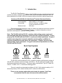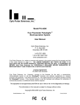
1
TM
Cyto Pulse Sciences, Inc.
Model PA-301
Pulse Booster TM
User Manual
Cyto Pulse Sciences, Inc.
P. O. Box 609
Columbia, MD 21045
1-410-787-1890
1-410-787-1891 FAX
e-mail: [email protected]
Cyto Pulse Sciences, Inc. makes no warranty with respect to the product except for the warranty set forth
in this Users Manual on page 5-1. The LIMITED WARRANTY SET FORTH ON PAGE 5-1 IS
EXCLUSIVE AND NO OTHER WARRANTY WHETHER WRITTEN OR ORAL, IS EXPRESSED OR
IMPLIED. Cyto Pulse Sciences, Inc. SPECIFICALLY DISCLAIMS IMPLIED WARRANTIES OF
MERCHANTABILITY AND FITNESS FOR A PARTICULAR PURPOSE.
License Agreement
PA-301 Pulse Booster
Cyto Pulse Sciences, Inc. (Licensor), conveys to the licensee, for fee paid, a nonexclusive,
nontransferable license to use the PulseAgile® hardware and software (equipment) for research
purposes into perpetuity. Cyto Pulse Sciences, Inc., has patent allowance and patents pending covering
the PulseAgile® and other processes. If the licensee wishes to use the hardware and software for
production or commercial purposes, an additional license shall be required.
The equipment is not approved by the FDA for
use with in vitro or in vivo diagnostics or therapy.
The information in this manual is subject to change without notice.
Copyright 2000-2005 Cyto Pulse Sciences, Inc.
PA301UMANrev.1-11/04
Price $100.00
PA-301 User Manual: Rev.1-12/04
TM
Cyto Pulse Sciences, Inc.
Model PA-301
Pulse Booster TM
User Manual
Cyto Pulse Sciences, Inc.
P. O. Box 609
Columbia, MD 21045
1-410-787-1890
1-410-787-1891 FAX
e-mail: [email protected]
Cyto Pulse Sciences, Inc. makes no warranty with respect to the product except for the warranty set forth
in this Users Manual on page 5-1. The LIMITED WARRANTY SET FORTH ON PAGE 5-1 IS
EXCLUSIVE AND NO OTHER WARRANTY WHETHER WRITTEN OR ORAL, IS EXPRESSED OR
IMPLIED. Cyto Pulse Sciences, Inc. SPECIFICALLY DISCLAIMS IMPLIED WARRANTIES OF
MERCHANTABILITY AND FITNESS FOR A PARTICULAR PURPOSE.
License Agreement
PA-301 Pulse Booster
Cyto Pulse Sciences, Inc. (Licensor), conveys to the licensee, for fee paid, a nonexclusive,
nontransferable license to use the PulseAgile® hardware and software (equipment) for research
purposes into perpetuity. Cyto Pulse Sciences, Inc., has patent allowance and patents pending covering
the PulseAgile® and other process. If the licensee wishes to use the hardware and software for
production or commercial purposes, an additional license shall be required.
The equipment is not approved by the FDA for
use with in vitro or in vivo diagnostics or therapy.
The information in this manual is subject to change without notice.
Copyright 2000-2005 Cyto Pulse Sciences, Inc.
PA301UMANrev.1-11/04
Cyto Pulse Sciences, Inc. P. O. Box 609, Columbia, MD 21045 410-787-1890
Price $100.00
i
PA-301 User Manual: Rev.1-12/04
Blank Page
ii
Cyto Pulse Sciences, Inc. P. O. Box 609, Columbia, MD 21045 410-787-1890
PA-301 User Manual: Rev.1-12/04
Table of Contents
Page
1.
Introduction
1-1
2.
PA-4000/PA-301 Set-up and Operation
2-1
2.1
2.2
2.3
2.4
2-1
2-1
2-3
2-3
3.
Introduction
Connecting the PA-301 to the PA-4000
PA-301 Front panel display
Power Up
Getting Started With the PA-301
3-1
3.1
Introduction
3-1
3.2
Application Software
3-1
3.2.1
3.2.2
3-2
3-2
3-2
3-3
3-4
3.2.3
4.
Applications
3-1
4.1
3-1
4.2
4.3
5.
Electroporation Protocol Screen
Protocol programming
3.2.2.1 Programming Pulse Amplitude
3.2.2.2 Programming Pulse Width
Run a protocol, PA-301Test.pro
Introduction
Electric Field Intensity
4-1
4.2.1
4-1
Rectangular vs. Exponential Decay Waveforms
Preparation of Electrocompetent Cells
4-2
4.3.1
4.3.2
4.3.3
4-2
4-2
4-3
E. coli and Gluconobacter
Lactococcus
E. Coli Transformation Example.
Customer Service
5-1
4.1
4.2
5-1
5-1
Limited Warranty
Customer Service
Cyto Pulse Sciences, Inc. P. O. Box 609, Columbia, MD 21045 410-787-1890
iii
PA-301 User Manual: Rev.1-12/04
List of Figures
Page
2-1
2-2
2-3
The Pulse Booster Electroporation System
Back Panel Connections
PA-301 Front Panel Display
2-1
2-1
2-2
3-1
3-2
3-3
3-4
PulseAgile® Opening Screen showing PA-301 Pulse BoosterTM attached
PulseAgile® Electroporation Protocol Programming Screen
PA-301Test.pro Protocol Log Report
Relationship among User-programmed volts, PA-4000 volts, and PA-301 volts
3-1
3-2
3-4
3-4
iv
Cyto Pulse Sciences, Inc. P. O. Box 609, Columbia, MD 21045 410-787-1890
PA-301 User Manual: Rev.1-12/04
Caution Notice
The PA-4000 to be connected to this instrument contains a high voltage power supply
that can be adjusted to beyond 1,000 volts. Additionally, the PA-301 can output a pulse of
3,000 volts. Such voltages can be lethal.
The user must read this manual carefully before the instrument is placed into operation.
Removing the cover may void the warranty.
Do not connect or disconnect the high voltage cable with the high voltage enabled. To
connect or disconnect the cable, turn line/mains power off and unplug line cord.
Do not open the cuvette holder while the high voltage is on. If a problem occurs during a
run, push the STOP/RESET button on the front panel.
If there are any questions about the operation of this instrument, call Cyto Pulse Customer
service.
Cyto Pulse Sciences, Inc. P. O. Box 609, Columbia, MD 21045 410-787-1890
v
PA-301 User Manual: Rev.1-12/04
Blank Page
vi
Cyto Pulse Sciences, Inc. P. O. Box 609, Columbia, MD 21045 410-787-1890
PA-301 User Manual Ch1: Rev.1-12/04
1. Introduction
The PA-301 Pulse BoosterTM add-on to the PA-4000 computer-controlled electroporator
provides the ability to establish higher electric fields required for smaller prokaryotic cells. All
pulse parameters are tunable to give the operator maximum flexibility in performing protocols.
Summary of PA-4000/PA-301 Pulse BoosterTM System Pulse Specifications
Pulse Amplitude
Pulse Width
Minimum Load
300 to 3000 V, in 15 V steps
0.001 to 0.600 ms, in 0.001 ms steps
0.100 ms maximum at 3000 V
200 ohms
This manual has been designed to help you realize the maximum benefit from using the
PA-4000/PA-301 PulseAgile® Pulse BoosterTM system. It contains information on how to
operate the electroporator, safety tips, and applications.
Note: The PA-4000 with the PA-301 contains a high voltage power supply and
was designed with safety features to protect the user and the equipment. If used
properly, the PA-4000 with the PA-301 is a safe and reliable instrument. Chapter 2
explains some important concepts related to operator safety in addition to
concepts needed for accurate use of the instrument. Chapter 2 must be read
before setting up this instrument. Our goal is the safe and productive use of the
PA-4000 with the PA-301.
Back Panel Symbols
Protective
Terminal
Conductor
Caution:
Refer to
documentation
Caution:
Risk of
electric shock
Chassis
Ground
The PA-4000, with the optional PA-301, is rated for operation with line/mains voltage of
100-240 VAC, maximum current of 2 amps, at 50-60 Hz. The AC mains power supply cord is
the disconnect device for this product. The power supply cord shall be a Type SJT, rated 300
Volts AC, 18 AWG, 105° C, 3-conductor including ground.
This unit is rated for environmental conditions of 5-40°C, 80% relative humidity to 31°C,
decreasing linearly to 50% relative humidity at 40°C, altitude to 2000 meters.
There are no operator replaceable parts inside the system; Cyto Pulse
recommends that the user not remove the cabinet covers.
Cyto Pulse Sciences, Inc. P. O. Box 609, Columbia, MD 21045 410-715-0990
1-1
PA-301 User Manual Ch1: Rev.1-12/04
Blank Page
1-2
Cyto Pulse Sciences, Inc. P. O. Box 609, Columbia, MD 21045 410-715-0990
PA-301 User Manual Ch2: Rev.1-12/04
2. PA-4000/PA301 Set-Up
2.1
Introduction
The PA-301 Pulse BoosterTM is an optional attachment to the PA-4000 PulseAgile®
Electroporator. It is a transformer that boosts the pulsed voltage output of the PA-4000 by a
factor of three. Subsequently, the pulsed electric field produced in a cuvette is 3-times that
produced by the PA-4000 alone. For example, electric field strengths of up to 7500 V/cm are
capable in a standard 4 mm cuvette. The
complete Pulse BoosterTM system consists of:
PA-4000
PA-301
PA4-SW
CE-20
CS-LN-__
CS-OPT
CUV-M
PA4-UMAN
PA301-UMAN
Electroporator
Pulse BoosterTM
PulseAgile® Software
Cuvette Holder
Line Cable set
Interface Cable Set
Cuvette Multi-Pack
PA-4000 User Manual
PA-301User Manual
Laptop shown is not included.
Figure 2-1: The PA-4000/PA-301 Pulse BoosterTM
Electroporation System
2.2
Connecting the PA-301 to the PA-4000
The PA-301 should be placed on top of the PA-4000. The Mains/Line Power Switch must
be off and the Mains/Line Power Cord must be unplugged from the PA-4000. Referring to
Figure 2-2, make the following connections:
• Connect the Option Interconnect cable between
the DB25 jacks on the back of the PA-301 and
PA-4000.
!DO NOT ATTACH TO A COMPUTER
PARALLEL PORT OR A PRINTER!
• Connect the high voltage cable between the
MHV jack on the back of the PA-4000 and the
MHV jack labeled Pulse In on the back of the
PA-301. This cord delivers the pulses
generated by the PA-4000 to the PA-301.
!DO NOT USE A CABLE WITH BNC PLUGS!
Figure 2-2: Back Panel Connections
PA-4000/PA-301
• Connect the HV cable with the MHV plug from
the CE-20 to the MHV jack labeled Pulse Out
on the back of the PA-301.
!DO NOT CONNECT A PA-96W TO THIS JACK!
• Connect the Cuvette Interlock cable from the CE-20 to the RCA-type phono jack on the back
panel of the PA-4000.
Cyto Pulse Sciences, Inc. P. O. Box 609, Columbia, MD 21045 USA 410-715-0990
2-1
PA-301 User Manual Ch2: Rev.1-12/04
2.3
PA-301 Front Panel Display
The PA-301 front panel display consists of
two light-emitting diodes (LED). Both of the
LEDs will light when the PA-301 is properly
connected to the PA-4000 and line/mains power
is turned on. The Interface LED indicates that
the DB25 interface cable is installed and
communication between the PA-4000 and the
PA-301 has been established. The Power LED
indicates that the PA-301 line/mains cord is
plugged into the back of the PA-4000 and that
the PA-301 is receiving power.
2.4
Figure 2-3: PA-301 Front Panel Display
Power Up
With all cables connected, including the serial communication cable from the host
computer, turn on line/mains power and start the PulseAgile® software. The set-up of the
system is now complete. The Getting Started chapter will give instruction on the proper
operation of the Pulse BoosterTM System.
2-2
Cyto Pulse Sciences, Inc. P. O. Box 609, Columbia, MD 21045 USA 410-715-0990
PA-301 User Manual Ch3: Rev.1-12/04
3. Getting Started with the PA-301
3.1
Introduction
The PA-301 Pulse BoosterTM System expands the high voltage pulse amplitude range
available to researchers. It is capable of producing rectangular wave pulses up to 3000. A
summary of the specifications is provided below. This Chapter will provide details regarding the
proper operation of the PA-301 using the PA-4000 PulseAgile® interface software.
3.2
Application Software
The PA-301 application software is a part of the PA-4000 PulseAgile® interface software.
It is accessible only when a PA-301 is connected using the DB25 interface cable as described in
Chapter 3. After installing the PA-301, close the Cuvette Holder handle, turn on the PA-4000,
and start the PulseAgile® software. The screen should appear as shown in Figure 3-1. In the
Options Connected area, look for a check mark in the box labeled 3:1 Transformer. If there is
no check, then the DB25 interface cable is not connected properly. Power down the system
and check the cable. If the problem persists, then call Cyto Pulse Sciences Customer Service.
Figure 3-1: PulseAgile® Opening Screen showing PA-301 Pulse BoosterTM attached
Cyto Pulse Sciences, Inc. P. O. Box 609, Columbia, MD 21045 USA 410-715-0990
3-1
PA-301 User Manual Ch3: Rev.1-12/04
3.2.1
Electroporation Protocol Screen
Click Electroporation and the screen should now appear as shown in Figure 3-2. The
default pulse parameters are shown in the various boxes. Details regarding programming
protocols were given in Chapter 4 of the PA-4000 User Manual, so this chapter will only cover
the software functions specific to the use of the PA-301.
3.2.2
Protocol programming
There are several differences between programming a Pulse BoosterTM protocol and a
standard PA-4000 protocol. Specifically, the minimum and maximum allowable pulse
amplitudes are different, and the maximum allowable pulse width varies with pulse amplitude
range. Additionally, there is no Low Range/High Range select; the PA-4000 reservoir capacitor
is fixed to the High Range value by default.
3.2.2.1
Programming Pulse Amplitude
The minimum pulse amplitude for the Pulse BoosterTM system is 300 volts. As an
exercise try this:
• Click on the Pulse Amplitude parameter box.
• Change the value to 100 volts.
• Click Replace
• Note how the Pulse Amplitude defaults back to 300 volts
Figure 3-2: PulseAgile® Electroporation Protocol Programming Screen
3-2
Cyto Pulse Sciences, Inc. P. O. Box 609, Columbia, MD 21045 USA 410-715-0990
PA-301 User Manual Ch3: Rev.1-12/04
The maximum pulse amplitude for the Pulse BoosterTM system is 3000 volts. So now try
this:
•
•
•
•
Click on the Pulse Amplitude parameter box.
Change the value to 3100 volts.
Click Replace
Note how the Pulse Amplitude defaults to 3000 volts
The minimum voltage step achievable is 15 volts (for a standard PA-4000 it is 2 volts in
Low Range and 5 volts in High Range). Here is an exercise to demonstrate this:
•
•
•
•
•
•
•
3.2.2.2
Click on the Pulse Amplitude parameter box.
Change the value to 310 volts.
Click Replace
Note how the Pulse Amplitude defaults to 300 volts
Change the value to 320 volts.
Click Replace
Note how the Pulse Amplitude defaults to 315 volts
Programming Pulse Width
The maximum allowable pulse width in the PA-301 Pulse BoosterTM System varies
according to the desired pulse amplitude. This insures that all pulses delivered meet Cyto Pulse
Sciences standard of pulse droop of ≤5%. The table below gives the maximum pulse width
allowed for ranges of pulse amplitude settings.
Pulse Amplitude
volts
300 - 585
600 - 795
810 - 1095
1110 - 1590
1605 - 2190
2205 - 3000
Maximum Pulse Width
ms
0.600
0.500
0.300
0.200
0.150
0.100
If values outside the above ranges are entered, the software will display an error message
window, and then set the pulse width to the maximum allowed value as demonstrated here:
•
•
•
•
Click on the Pulse Width parameter box.
Change the value to 1.000 ms
Click Replace
The following Message Box should display:
•
Click OK and note how the Pulse Width is now set to 0.600 ms.
Cyto Pulse Sciences, Inc. P. O. Box 609, Columbia, MD 21045 USA 410-715-0990
3-3
PA-301 User Manual Ch3: Rev.1-12/04
3.2.3
Run a protocol, PA-301Test.pro
Before running this protocol, check that there is a cuvette installed in the cuvette holder
and the handle is closed. For this test, an empty 4mm or greater cuvette is recommended.
•
•
•
•
•
Open the protocol file PA-301Test.pro located in the /protocol folder.
Click Turn HV On.
After the system charges, note that the Power Supply Voltmeter reads 1000 volts,
not 3000 volts. This is the case because the PA-4000 is going to deliver a 1000
volt pulse to the PA-301, which in turn will boost the pulse voltage by a factor of
three, subsequently delivering a 3000 volt pulse to the cuvette.
Click Start.
The log report should look something like that shown in Figure 3-3.
Protocol File: PA-301Test.pro
12-7-2004-3 13:59:40
Mode: Electroporation w/ 3:1 Transformer
Monitor Voltage x 3
>GRP
>1
NUM
1
WIDTH
0.100
INTVL
0.50
SetV
1000
MonV
1000
>GRP
>2
NUM
1
WIDTH
0.200
INTVL
0.50
SetV
500
MonV
500
>GRP
>3
NUM
1
WIDTH
0.400
INTVL
0.50
SetV
250
MonV
255
>GRP
>4
NUM
1
WIDTH
0.600
INTVL
0.50
SetV
125
MonV
130
>Estimated load > 100 ohms
>Estimated conductance < 0.001 siemens
$
Figure 3-3: PA-301Test.pro Protocol Log Report
It is important to note that when programming a protocol, the user will enter the pulse
amplitude of the waveform delivered to the sample. That is, the pulse out of the PA-301 and to
the test sample. The PulseAgile® software, however, is monitoring the voltage set inside the
PA-4000, which will be one-third of the output pulse. This concept is illustrated in Figure 3-4.
Figure 3-4: Relationship among User-programmed volts, PA-4000 volts, and PA-301 volts
3-4
Cyto Pulse Sciences, Inc. P. O. Box 609, Columbia, MD 21045 USA 410-715-0990
PA-301 User Manual Ch3: Rev.1-12/04
4. Applications
4.1
Introduction
The general principles for electroporation of prokaryotic organisms are the same as those
described for eukaryotic organisms in the PA-4000 User Manual. However, the smaller size of
the prokaryotic cells and the presence of a cell wall around many prokaryotic cells, present
challenges to efficient transfection through electroporation.
4.2
Electric Field Intensity
Electric field intensity is the most important pulse parameter determining electroporation
efficacy. Since the required electric field is inversely proportional to cell diameter, smaller cells
require higher electric fields. There is a wide range of electric field intensity (3-30 KV/cm)
reported in the literature for electroporation of small prokaryotic cells (most are for E. coli). The
majority of protocols use electric fields around 12 KV/cm. In contrast, the electroporation of
eukaryotic cells is generally performed at electric field intensities on the order of 1 kV/cm to 2.5
kV/cm.
4.2.1
Rectangular vs. Exponential Decay Waveforms
Most published methods for electroporation of E. coli describe exponential decay pulses.
The PA-4000 with PA-301 delivers a rectangular wave pulse. There is no direct way to convert
an exponential decay pulse protocol to a rectangular wave pulse protocol. For best results, a
range of parameters should be tried initially
Here are guidelines that can be followed to assist in making that conversion.
1. Rectangular wave pulses are more precisely controlled than exponential decay
pulses. For instance, the pulse width can be fine tuned to avoid overheating.
2. Since rectangular wave pulses are shorter in duration than exponential decay pulses,
a higher pulsed electric field may be required. For example, a protocol designed
around a 12 KV/cm field delivered by a exponential decay pulser might require that a
20 KV/cm field be used if redesigned for a rectangular wave pulser. The Pulse
BoosterTM system can produce a field intensity of up to 30 KV/cm in a 1mm cuvette.
3. Multiple rectangular wave pulses may be better than single pulses.
4. Since less heat is generated using rectangular wave pulses, the cells should not be
pre-cooled. Electroporation should be done at room temperature.
5. More cells will be viable after using rectangular wave electroporation.
Rectangular and exponential decay waveform electroporation do have some common
requirements, however.
•
Low conductivity medium should be used to reduce arching and heat
•
Electroporation competent E. coli (or other bacteria) should be used
Cyto Pulse Sciences, Inc. P. O. Box 609, Columbia, MD 21045 USA 410-715-0990
4-1
PA-301 User Manual Ch3: Rev.1-12/04
4.3
Preparation of Electrocompetent Cells
Bacterial cells need to be prepared for electroporation by making them electrocompetent.
Electrocompetent cells can be purchased from companies such as Invitrogen. Alternatively,
one of the following procedures can be used.
4.3.1
E. coli1 and Gluconobacter2
1. Grow 1 Liter culture to A600 of 0.5. This usually requires growing a small culture
overnight from a colony then inoculating two 500 ml cultures on a shaker at 37o C.
2. Add culture to 500 ml centrifuge tubes and cool to 4o C.
3. Centrifuge at 3000 X g for 10 minutes.
4. Discard supernatant and add 250 ml ice cold water or 1 mM HEPES pH 7.0.
5. Centrifuge at 3000 X g for 10 minutes.
6. Discard supernatant and add 40 ml ice cold water or 1 mM HEPES pH 7.0 and transfer
to 50 ml conical tube.
7. Centrifuge at 3000 X g for 10 minutes.
8. Discard supernatant and add 20 ml ice cold10% glycerol in water.
9. Centrifuge at 3000 X g for 10 minutes.
10. Aspirate supernatant and combine all pellets in 1.5 ml cold 10% glycerol in water.
11. Aliquot in small amounts (40 to 80 µl).
12. Freeze in liquid nitrogen or an ethanol/dry ice bath.
13. Store at -80o C.
4.3.2
Lactococcus3
1. Grow L. lactis in GM17, 30o C to A600 of 0.5
2. Dilute cells and grow in SGM17 containing 0.2 to 4% glycine (strain dependent) to A600
of 0.5
3. Centrifuge 5000 X g, 4 oC
4. Discard supernatant and add ice cold10% glycerol in 0.5 M sucrose
5. Centrifuge 5000 X g, 4 oC
6. Discard supernatant and add ice cold10% glycerol in 0.5 M sucrose
7. Centrifuge 5000 X g, 4 oC.
8. Discard supernatant, add 1/100 culture volume of ice cold 10% glycerol in 0.5M sucrose.
9. Use immediately or store at -80 oC.
4-2
Cyto Pulse Sciences, Inc. P. O. Box 609, Columbia, MD 21045 USA 410-715-0990
PA-301 User Manual Ch3: Rev.1-12/04
4.3.3
E. Coli Transformation Example.
The following procedure was performed to transform E. coli with a plasmid containing a
Kanamycin resistance gene:
1. Prepared culture plates in advance:
Mix LB agar and water.
Microwave to boiling.
Microwave on low 1 minute.
Cool to 70o C.
Add Kanamycin if desired (10 µl/ml of 100 µg/ml Kanamycin).
Pour 13 mL into 100 mm petri dishes and cool to room temperature.
2. Thawed 1 vial of Invitrogen Electromax® DH5α-E cells.
3. Added 2 µL plasmid (2.5 µg/mL to 100 µL cells. Note, as little as 20 µL cells can be
used.
4. Added cells to a 1 mm gap cuvette.
5. Applied three pulses:
2000 volts amplitude
100 µs pulse width
0.2 second interval
using a Cyto Pulse Sciences PA-4000/PA-301 Pulse BoosterTM system.
6. Added 1 ml SOC medium, mix well and moved to Falcon™ tube.
7. Prepared 10 fold dilutions.
8. Plated dilutions by adding 5 µl cell suspension to culture plate with Kanamycin and to
an identical plate without Kanamycin.
9. Incubated 18 hours 37oC.
10. Counted colonies and analyzed selected colonies using an Invitrogen Clone
Checker® System.
Results: 130,000 transformed colonies were obtained (65 colonies counted at 1:100
dilution assaying 1/20 of the cell suspension)
References:
1. Nickoloff (editor), Methods in Molecular Biology Vol 47, Miller, EM, Nickoloff, JA, Chapter
8, Echerichia coli Electrotransformation,1995, 105-113
2. Mostofa, HE, Heller, KJ, Geis, A, Cloning of Escherichia coli lacZ and lacY genes and
their expression in Gluconobacter oxydans and Acetobacter liquifaciens, Applied and
Environmentqal Microbiology, 2002, 68(5):2619-2623
3. Nickoloff (editor), Methods in Molecular Biology Vol 47, Chapter 19, Transformation of
Lactococcus by electroporation, 1995, 195-199
Cyto Pulse Sciences, Inc. P. O. Box 609, Columbia, MD 21045 USA 410-715-0990
4-3
PA-301 User Manual Ch3: Rev.1-12/04
Blank Page
4-4
Cyto Pulse Sciences, Inc. P. O. Box 609, Columbia, MD 21045 USA 410-715-0990
PA-301 User Manual Ch5: Rev.1-12/04
5. Customer Service
5.1
Limited Warranty
CYTO PULSE products are warranted against defect in materials and workmanship. If
the customer provides notice of such a defect during warranty period, CYTO PULSE, at its
option, will either repair or replace the products, which were found to be defective. The limited
warranty set forth above is exclusive and no other warranty whether written or oral, is expressed
or implied. CYTO PULSE specifically disclaims implied warranties of merchantability and
fitness for a particular purpose.
EXCEPT AS SET FORTH ABOVE, CYTO PULSE MAKES NO WARRANTY WITH RESPECT
TO THE PRODUCT, AND IN NO EVENT, REGARDLESS OF CAUSE, SHALL CYTO PULSE
BE LIABLE FOR INDIRECT, SPECIAL, OR CONSEQUENTIAL DAMAGES OR OTHER
LOSSES OF ANY KIND ARISING FROM BREACH OF WARRANTY OR OTHER USES OF
THIS PRODUCT. CYTO PULSE’S OBLIGATION TO REPAIR OR TO REPLACE TO THE
EXTENT SET FORTH ABOVE CONSTITUTES THE EXCLUSIVE REMEDIES OF THE
CUSTOMER FOR ANY BREACH OF WARRANTY.
This warranty shall not apply to products, which after inspection by CYTO PULSE, were
found to be improperly used or to have been modified in any manner. CYTO PULSE
recommends that the user not open the product cabinet. This limited warranty is valid for two
years from the date of shipment.
5.2
Customer Service
If the user believes that there is a defect in the CYTO PULSE product, the customer
should contact CYTO PULSE Customer Service by e-mail at [email protected] or
phone 410-787-1890, or contact the local CYTO PULSE representative. A determination if the
product is still in warranty will be made. If the warranty period is still in effect, the user will be
given an authorization number (RMA) to return the product. If after receipt and inspection the
product is found to be defective, it will be replaced or repaired and returned to the customer. If
the product is found to have been modified or misused, the user will be given a quote for repair.
If the warranty period has expired and the user requests repair, CYTO PULSE will inspect the
product and provide a written quote for repair. The user must provide a purchase order number
before the product will be repaired. If the unit is damaged in shipment, the user must recover
the insured value to replace or repair from the carrier.
Cyto Pulse Sciences, Inc. P. O. Box 609, Columbia, MD 21045 USA 410-715-0990
5-1
PA-301 User Manual Ch5: Rev.1-12/04
Blank page
5-2
Cyto Pulse Sciences, Inc. P. O. Box 609, Columbia, MD 21045 USA 410-715-0990