1
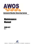
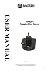
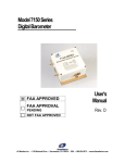
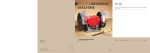
Model 6496
Freezing Rain Sensor
User’s
Manual
Rev. A
All Weather Inc. • 1165 National Drive • Sacramento, CA 95834 • USA • 800.824.5873 • www.allweatherinc.com
Copyright © 2012, All Weather, Inc.
All Rights Reserved. The information contained herein is proprietary and is provided solely for the purpose of
allowing customers to operate and/or service All Weather, Inc. manufactured equipment and is not to be released,
reproduced, or used for any other purpose without written permission of All Weather, Inc.
Throughout this manual, trademarked names might be used. Rather than put a trademark (™) symbol in every
occurrence of a trademarked name, we state herein that we are using the names only in an editorial fashion and to
the benefit of the trademark owner, and with no intention of infringement. All Weather, Inc. and the All Weather,
Inc. logo are trademarks of All Weather, Inc.
Disclaimer
The information and specifications described in this manual are subject to change without notice.
Latest Manual Version
For the latest version of this manual, see the Product Manuals page under Reference on our web site at
www.allweatherinc.com/.
All Weather, Inc.
1165 National Drive
Sacramento, CA 95834
Tel.: (916) 928-1000
Fax: (916) 928-1165
Contact Customer Service
•
Phone support is available from 8:00am - 4:30pm PT, Monday through Friday. Call 916-928-1000 and ask for
“Service.”
•
Online support is available by filling out a request at www.allweatherinc.com/customer/support.html
•
E-mail your support request to [email protected]
Model 6496 Freezing Rain Sensor
User’s Manual
Revision History
Revision
A
Date
2012 Sept 24
Summary of Changes
Initial release.
Model 6496 Freezing Rain Sensor
User’s Manual
TABLE OF CONTENTS
1. OVERVIEW .........................................................................................................................1
1.1 Accessories ................................................................................................................................ 1
2. FUNCTIONAL DESCRIPTION ............................................................................................2
3. DATA COMMUNICATION ...................................................................................................3
3.1 Data Output ............................................................................................................................... 3
3.1.1 Communication Parameters ............................................................................................. 3
3.1.2 Data Format ..................................................................................................................... 3
3.1.3 Poll Command ................................................................................................................. 5
4. UNPACKING AND INSTALLATION ....................................................................................6
4.1 Unpacking.................................................................................................................................. 6
4.2 Installation ................................................................................................................................. 6
4.2.1 Mechanical Mounting ...................................................................................................... 6
4.2.2 Power Connection ............................................................................................................ 8
4.2.3 Data Connection............................................................................................................... 9
4.2.4 Final Steps........................................................................................................................ 9
5. OPERATION ..................................................................................................................... 10
5.1 Power Interruptions ................................................................................................................. 10
5.2 Built-In Test (BIT) Capabilities .............................................................................................. 10
5.2.1 Hardware Built-In Test .................................................................................................. 10
5.2.2 Continuous Built-In Test................................................................................................ 10
5.2.3 BIT Failure That Disables Ice Status Output ................................................................ 11
5.2.4 Initiated Built-In Test (BIT)........................................................................................... 12
5.3 Operator-Initiated Tests ........................................................................................................... 12
5.4 Correlation Counting ............................................................................................................... 12
6. MAINTENANCE ................................................................................................................ 14
6.1 Periodic Maintenance .............................................................................................................. 14
6.1.1 Monthly Maintenance .................................................................................................... 14
6.1.2 Triannual Maintenance .................................................................................................. 14
6.1.3 Annual Maintenance ...................................................................................................... 14
7. TROUBLESHOOTING ...................................................................................................... 15
8. REMOVAL AND REPLACEMENT .................................................................................... 16
10. SPECIFICATIONS .......................................................................................................... 17
11. WARRANTY .................................................................................................................... 19
Model 6496 Freezing Rain Sensor
User’s Manual
1. OVERVIEW
The Model 6496 Freezing Rain Sensor uses an ultrasonically vibrating probe to detect the presence of
icing conditions. The 40 kHz vibrating frequency of the probe decreases as ice, frost, or wet snow
accumulate. Once these types of frozen precipitation have accreted on the probe to a thickness of
0.020" (0.5 mm), the frequency decreases by approximately 130 Hz and an internal heater inside the
probe assembly turns on to deice the probe.
The internal heater draws 35 W during deicing and stays on for 60 seconds. The sensing probe cools
within a few seconds.
A 24-byte string reporting whether ice is present and status information for the Freezing Rain Sensor
is sent to the AWOS Data Collection Platform (DCP) when polled. The DCP combines information
from the Freezing Rain Sensor with data from other AWOS sensors to generate reports describing the
nature of the freezing rain ice, frost, or wet snow that has accreted on the sensor probe.
1.1 ACCESSORIES
The following accessories are available for the Model 6496 Freezing Rain Sensor.
Part Number
Description
M105737-00
Probe Assembly Replacement Gasket
M488397-00
Mounting Kit
M491742-00
Data Cable (connects Model 6496 Freezing Rain
Sensor to DCP)
M491745-01
50 ft Power Cable (Model 6496 Freezing Rain
Sensor power connector to bare wires)
1
Model 6496 Freezing Rain Sensor
User’s Manual
2. FUNCTIONAL DESCRIPTION
The Model 6496 Freezing Rain Sensor is mounted on an enclosure containing the power supplies and
communication interface (see Figure 1). Extensive internal self-testing identifies problems and
provides diagnostic information to indicate whether the sensor is operating properly.
Figure 1. Model 6496 Freezing Rain Sensor Enclosure
The Probe Assembly (M482221‐00) contains the actual Freezing Rain Sensor probe and its associated
electronics.
The Power Input Board (M404802-01) accepts AC power and provides 24 V DC to the Freezing Rain
Sensor probe and its associated electronics. A 12 V DC power supply also draws its power from the
Power Input Board to supply power to the the serial converters that output the RS-422 data from to the
Freezing Rain Sensor probe to the RS-485 data output connector on the enclosure.
2
Model 6496 Freezing Rain Sensor
User’s Manual
3. DATA COMMUNICATION
3.1 DATA OUTPUT
The data is output from the Model 6496 Freezing Rain Sensor over an asynchronous RS-485
interface. The data are output in response to a poll command.
3.1.1 Communication Parameters
Table 1 lists the settings for the communication parameters.
Table 1. 6496 Freezing Rain Sensor Communication Settings
Parameter
Setting
Baud Rate
Data Bits
4800 bps
8
Parity
None
Stop Bits
1
Handshaking
None
3.1.2 Data Format
The serial string output from the Model 6496 Freezing Rain Sensor has the following format.
Table 2. Freezing Rain Sensor Serial Output String Data Format
Byte
Bit
Definition
Comments/Interpretation/Range
7 (MSB)
String ID
0
6
0 (first)
5–3
Unused
2
Probe Heater State
1 = Heater ON
0 = Heater OFF
1
Ice Output
1 = Ice
0 = No ice
0
Status Output
1 = Failure
0 = OK (no failure)
Oscillator frequency count in hex
Frequency = 774060000/Dec (oscillator)
7
Unused
1 = Active
6
Oscillator failure — frequency
too high
1–2 (oscillator
frequency)
3 (ERRSTAT1)
Reserved for future use
3
Model 6496 Freezing Rain Sensor
Byte
User’s Manual
Bit
Definition
Comments/Interpretation/Range
5
Oscillator failure — frequency
too low
4
EEPROM failure
3
RAM failure
2
ROM failure
1
Watchdog Timer failure
0
Power Interrupt Timer failure
7–6
Probe Heater failure
00 = Probe Heater OK
01 = Probe Heater always On or OPEN
10 = Probe Heater always OFF
11 = Probe Heater ON with 1 enable
5
Deicing failure
1 = Active
4–0
Unused
3 (ERRSTAT2)
5–7 (on-time
count)
Power-On time count (in hex) in
10-minute increments
000000–01FFFF
8–9 (cold start
count)
Cold Start Power-On count
0000–FFFF
10–11 (ice count)
Ice events
0000–FFFF
12 (failures count)
Total failures encountered.
This number is incremented
each time the ice detector
transitions from OK to fail.
00–FF
7–4
Oscillator Frequency failure
count
0–F
3–0
Heater failure count
0–F
13
(Failure Detail 1)
14
(Failure Detail 2)
Not used
15
(Last Error 1)
See ERRSTAT1
16
(Last Error 2)
See ERRSTAT2
17
(Second Last
Error 1)
See ERRSTAT1
18
(Second Last
Error 2)
See ERRSTAT2
4
Model 6496 Freezing Rain Sensor
Byte
Bit
User’s Manual
Definition
Comments/Interpretation/Range
19
(Permanent
Error 1)
See ERRSTAT1
20
(Permanent
Error 2)
See ERRSTAT2
21 (software
version)
Software Version per VDD/SC1
00–FF
22 (correlation
count)
0.01" ice accretion increments
since power-on
00–FF
23 (checksum)
Summation (1 byte wide) of
bytes 0–22
00–FF
3.1.3 Poll Command
The poll command is summarized below, where 00 is the address. <CR> and <LF> are a carrier return
and line feed.
FRRA00<CR><LF> – DCP Poll Command
5
Model 6496 Freezing Rain Sensor
User’s Manual
4. UNPACKING AND INSTALLATION
4.1 UNPACKING
The Model 6496 Freezing Rain Sensor is a precision instrument and should be handled with extreme
care at all times.
When the equipment is received, check that all parts listed on the packing slip are accounted for, and
inspect the equipment for visible transport damage. Report any damage or discrepancies to All
Weather, Inc. Customer Service.
Figure 2 shows the protective covers that are around the probe and the probe assembly at the top of
the Model 6496 Freezing Rain Sensor enclosure. Do not remove these protective covers until the
enclosure installation has been completed.
Figure 2. Probe and Probe Assembly Protective Covers
4.2 INSTALLATION
The Model 6496 Freezing Rain Sensor must be firmly mounted to a vertical 2½" pipe for proper
operation. The Model 6496 Freezing Rain Sensor should be installed in an open area away from trees,
buildings, or other obstructions. Mount the Freezing Rain Sensor so that the probe assembly is
oriented into the prevailing wind.
4.2.1 Mechanical Mounting
Freezing Rain Sensor
The Freezing Rain Sensor mounts on the mast using the M488397-00 Mounting Kit. Refer to Figure 3
and Figure 4 during installation.
Mount the Freezing Rain Sensor on the mast with the top of the enclosure 5’6" (167 cm) from ground
level, or at least 3 feet (1 meter) above the maximum snow level using Mounting Kit M488261-00.
6
Model 6496 Freezing Rain Sensor
User’s Manual
Ground Cable
In order for the Freezing Rain Sensor’s built-in lightning protection to function properly, the
Ceilometer must be grounded. To install grounding, follow the steps below (see Figure 3).
1. Drill and tap a ¼ -20 hole in the mast. Install a grounding clamp in the hole.
2. Connect one end of a length of ground cable (4 AWG multi-strand insulated wire, available
from All Weather, Inc. as P/N T605000), to the grounding clamp on the mast.
3. Connect the other end of the ground cable to the ground lug on the underside of the Freezing
Rain Sensor.
4. Finally, connect a bare copper ground wire between the ground clamp on the mast and an
installed ground rod.
Figure 3. Freezing Rain Sensor Mounting
7
Model 6496 Freezing Rain Sensor
User’s Manual
Figure 4. Mast Mounting Details
4.2.2 Power Connection
1. Connect the power cord’s circular connector to the POWER connector on the bottom of the
Freezing Rain Sensor enclosure (see Figure 5).
2. Connect the other (unterminated) end of the cable to a suitable AC source in a junction box —
BLACK wire is hot, WHITE wire is common, and GREEN wire is ground.
It is recommended that power to the junction box be shut off at the breaker panel while the
wiring connections are made inside the junction box.
Figure 5. Freezing Rain Sensor Connectors
8
Model 6496 Freezing Rain Sensor
User’s Manual
4.2.3 Data Connection
1. Connect the data cable’s circular connector to the DATA connector on the bottom of the
Freezing Rain Sensor enclosure (see Figure 5).
2. Connect the other (unterminated) end of the cable to the RS-485
connections on terminal block TB4 of the Model 1190 DCP.
Connect the GREEN ground wire to pin 7 of terminal block TB4.
Connect the BLACK wire (RS-485 +) from the signal cable to pin 1
or 3, and connect the WHITE wire (RS-485 –) to pin 2 or 4 of terminal
block TB4. These pin connections are also used for RS-485
connections from other sensors.
Wait until all wires from any other sensors have been inserted
when connecting more than one wire to a terminal block pin
before securing the terminal block screw.
4.2.4 Final Steps
1. Check that the ON/OFF power switch inside the enclosure (Figure 1) is ON.
2. Close and fasten the enclosure door.
3. Remove the two probe protective covers shown in Figure 2.
4. Ensure that the circuit breaker on the breaker panel is in the “ON” position.
9
Model 6496 Freezing Rain Sensor
User’s Manual
5. OPERATION
The Freezing Rain Sensor operates automatically, and sends data packets to the DCP. There are no
controls or indicators on the sensor itself.
5.1 POWER INTERRUPTIONS
The Freezing Rain Sensor uses a power-fail monitor to verify the supply voltage. If a power fault
lasting more than 200 ms is detected, the Freezing Rain Sensor will report a failure in the STATUS
output.
5.2 BUILT-IN TEST (BIT) CAPABILITIES
The Freezing Rain Sensor has hardware, continuous, power-up, and operator-initiated tests. Whenever
a failure is detected and verified, the Freezing Rain Sensor stops detecting and annunciating icing
conditions, and the internal probe heaters are disabled. Failures detected in Initiated and Continuous
BIT are counted and enunciated once they have been verified.
Failures are verified by delaying (debouncing) the failure for a period of time to minimize or eliminate
nuisance errors, Failures detected in Initiated BIT are latched, and power must be cycled off and on to
clear a failure. If failures detected in Continuous BIT go away, the probe returns to normal mode, and
once again enables all detection functions.
5.2.1 Hardware Built-In Test
The hardware BIT consists of a watchdog timer that forces the microcontroller in the Probe Assembly
to re-initialize if it does not receive a strobe every 1.6 seconds. An internal voltage monitor forces the
microcontroller to the reset state if the internal 5 V DC power supply falls below 4.65 V DC and holds
it there until the power supply returns above 4.65 V DC. No output strings are transmitted while the
microcontroller is reset.
5.2.2 Continuous Built-In Test
The Continuous BIT verifies the following operations.
•
The internal probe heater is in the correct state. The return leg of the heater is monitored.
•
The discrete output for ice is in the correct state. This discrete output is fed back to the microcontroller through a passive voltage divider and voltage comparator.
•
The probe oscillator is operating correctly. Frequencies between 39.00 and 40.15 kHz are valid.
•
The internal probe heater is deicing correctly. Once it has turned on, the internal probe heater
must cause the probe oscillator frequency to return to at least 39.97 kHz within the 25 second
timeout, otherwise the internal probe heater is considered to have failed.
10
Model 6496 Freezing Rain Sensor
User’s Manual
5.2.3 BIT Failure That Disables Ice Status Output
The ice status output is disabled by Continuous and Initiated BIT failures as shown in Table 3. Ice
detection is disabled when these failures occur because the integrity of the ice detection capability
may be compromised.
Table 3. BIT Failure Information
Failure Type
Ice Detection
Disabled
Oscillator Failure — Frequency Too High
×
×
Oscillator Failure — Frequency Too Low
×
×
Initiated BIT
Continuous BIT
×
EEPROM Failure
RAM Failure
×
×
ROM Failure
×
×
Watchdog Timer Failure
×
Power Interrupt Timer Failure
×
Power Fault Monitor Failure
×
Internal Probe Heater Always ON
Active Test
Passive Test
Internal Probe Heater Always OFF
Active Test
Passive Test
Internal Probe Heater Always ON
with 1 Enable
×
Deicing Failure
Clear Only
Set Only
×
Unknown Reset Failure
Note 1: The software no longer reports the ice status once a failure is annunciated..
Note 2: In Continuous BIT, the “Internal Probe Heater Always OFF” failure is set
when the heater is ON and a deicing failure has been detected. If the frequency
indicates that the ice has been removed within the expected time, the software will
not annunciate an internal probe heater failure. In this case, the actual failure is
most likely caused by a problem in the heater feedback circuitry rather than the
heater control circuitry. The failure will be annunciated the next time the Initiated
BIT is performed.
11
Model 6496 Freezing Rain Sensor
User’s Manual
5.2.4 Initiated Built-In Test (BIT)
The Initiated BIT is performed at initial power-up of the Freezing Rain Sensor and following power
interruptions that last longer than than 200 ms. The Initiated BIT consists of the following tests:
•
The ice and fault status outputs are set in the serial output string so monitoring electronics or
test equipment can verify activation.
•
The Freezing Rain Sensor internal probe heater is turned on for a short period of time to verify
correct operation of the heater, heater control circuit, and heater feedback circuit.
•
The correct operation of the watchdog timer is verified by simulating a microcontroller timeout and waiting for a reset input.
•
Proper ROM operation is verified by computing a checksum of the ROM contents and
comparing against a a checksum stored in the ROM.
•
RAM operation is verified by writing and reading test bytes.
•
The Power Interrupt Timer is checked by verifying its transitions to a “warm” state after
performing a “cold” start.
•
The power fail input is pulled down to verify a power failure is detected.
•
Each time the critical data from the EEPROM are read, a checksum is read and compared to
the checksum computed from the contents. Each time critical data are written to the serial
EEPROM, a checksum is computed and stored with the data.
•
Resets for unknown reasons (such as reset from the watchdog timer) are detected.
5.3 OPERATOR-INITIATED TESTS
The operator can test the freezing rain sensor functionality by squeezing the tip of the probe between
the index finger and thumb. This simulates icing by decreasing the frequency of the probe.
C A UT ION
B e c areful if the probe has jus t been through a deic ing c yc le s inc e it may
reac h temperatures up to 204°C . C lean the probe after touc hing it as oil
res idue from s kin will affec t the performanc e of the probe.
5.4 CORRELATION COUNTING
The Freezing Rain Sensor tracks the ice accumulation on the probe during an icing event. The
correlation count helps the Freezing Rain Sensor track the amount of ice that has accumulated on the
probe during the icing event.
Each correlation count corresponds to a frequency decrease of 65 Hz during the icing event and
reflects 0.010" (0.25 mm) of ice buildup. The correlation count, which ranges from 0 to 255, does not
take into account the change in collection efficiency caused by ice buildup. The value is no longer
incremented once a correlation count of 255 is reached.
12
Model 6496 Freezing Rain Sensor
User’s Manual
The Freezing Rain Sensor compensates for the operation of the internal probe heater by adding a value
(ranging from 0 to 6) to the correlation count when the ice detection cycle is completed
The correlation count is reported in Byte 22 of the serial output string (see Error! Reference source
not found.).
The correlation count is initialized to zero when the Freezing Rain Sensor powers up.
13
Model 6496 Freezing Rain Sensor
User’s Manual
6. MAINTENANCE
6.1 PERIODIC MAINTENANCE
Tools and Equipment Required
•
Soft cotton cloth (lint free)
•
Isopropyl alcohol
6.1.1 Monthly Maintenance
Inspect all mounting hardware and cable assemblies for wear and damage; repair or replace as needed.
6.1.2 Triannual Maintenance
1. Inspect all mounting hardware and cable assemblies for wear and damage; repair or replace as
needed.
2. Visually inspect the probe surface for contaminants such as dirt, oil, fingerprints, etc.
3. If any contaminants are present, clean probe using isopropyl alcohol and soft cotton cloth.
T he freezing rain s ens or probe as s embly will be hot if the s ens or rec ently
WA R NING
c ompleted a deic e c yc le. E ns ure that the probe as s embly has c ooled before
c leaning the probe. While in the deic e mode, the probe will radiate a
s ignific ant amount of heat. T his c an be obs erved by plac ing a hand c los e to,
but not on, the s ens or probe. A lways avoid direc t c ontac t of the probe with
s kin to avoid a potential burn hazard.
C A UT ION
Do not touc h the probe with bare hands , as oil res idue from s kin will affec t
the performanc e of the s ens or.
6.1.3 Annual Maintenance
No additional maintenance beyond that described above for monthly and triannual maintenance is
required.
14
Model 6496 Freezing Rain Sensor
User’s Manual
7. TROUBLESHOOTING
Symptom
Freezing rain data missing, or
“F” displayed for sensor status
Possible Causes
Loose cable or connector
No power to Freezing Rain
Sensor
Freezing Rain Sensor
software locked up
Freezing Rain Sensor has
failed
Freezing rain data intermittent
Loose cables or connectors
Freezing Rain Sensor is faulty
Freezing Rain data inaccurate
Freezing Rain Sensor
requires maintenance
Freezing Rain Sensor has
operational errors
Freezing Rain Sensor
software has locked up
Ice fails to melt from probe
Freezing Rain Sensor internal
probe heater or processor has
failed or software has locked
up
15
Action
Check all cables and
connectors. Repair or
replace, if necessary
Check main power to the
sensor is ON
Cycle power to sensor. If no
recovery, cycle power to the
DCP. If no recovery, replace
sensor.
Consult the SYSLOG for
errors prior to the sensor
going missing to confirm
faulty operation before failure.
Replace sensor, if necessary.
Check all cables and
connectors. Repair or
replace, if necessary.
Consult the SYSLOG for
errors and examine the
freezing rain status word for
possible causes of the
problem. Replace sensor, if
necessary.
Perform complete
maintenance.
Cycle power to sensor. If no
recovery, cycle power to the
DCP. If no recovery, replace
sensor.
Cycle power to sensor. If
data still inaccurate, replace
sensor.
Cycle power to sensor. If ice
still fails to melt, replace
sensor.
Model 6496 Freezing Rain Sensor
User’s Manual
8. REMOVAL AND REPLACEMENT
IMPORTANT
Observe ESD grounding procedures when handling modules.
Do not change modules during weather events; never allow precipitation to enter the
interior of the Freezing Rain Sensor.
Whenever a module is being changed, the power should be shut off remotely. The only
time the power should be on with the Freezing Rain Sensor door open is when checking
system operation during troubleshooting.
To gain access to the Probe Assembly, open the enclosure door using a screwdriver to release the two
latches.
Figure 6. Freezing Rain Sensor Probe Assembly
1. The Probe Assembly (part number M482221‐00) is mounted at the top of the Freezing Rain
Sensor enclosure.
2. Disconnect the wire connector at the bottom of the Probe Assembly.
3. Remove the four screws securing the Probe Assembly to the top of the Freezing Rain Sensor
enclosure.
4. Remove the Probe Assembly from the unit.
5. When installing the new Probe Assembly, replace the gasket (part number M105737-00)
before installing the new Probe Assembly and securing it in place with the four screws.
6. Reconnect the wire connector to the bottom of the Probe Assembly. The connector is keyed to
facilitate lining up the pins to make the connections correctly.
16
Model 6496 Freezing Rain Sensor
User’s Manual
10. SPECIFICATIONS
Parameter
Specification
Set Point
Ice signal activates when ice thickness on probe exceeds
0.020 ± 0.005 in (0.5 ± 0.1 mm)
Deicing
Operates when ice thickness on probe
exceeds the set point
Discrete Output Signals
• Ice signal
• Operating status signal
Built-In-Test (BIT)
• Performed at initial power-up.
If a failure is detected and verified, the sensor stops
detecting and annunciating ice presence, the probe
heaters are disabled; and a failure is annunciated.
• Hardware and software BIT verifies that internal
electronics are functioning properly during ongoing
operation.
Output Format
Serial Output
RS-485 (half duplex)
Serial Output Baud Rate
4800 bps
Serial Port Parameter Setting
8-N-1 (8 data bits, no parity, 1 stop bit)
Conxall® Mini-Con-X®
7280-5SG-300 Field Connector
Serial Connector
Data Output
In response to poll command
Electrical
85–265 V AC
47–64 Hz, 50 W
Supply Voltage
Environmental
Operating Temperature
-55 to +70ºC
(-67 to +158ºF)
Storage Temperature
-65 to +70ºC
(-85 to +158ºF)
Humidity
0–100% (noncondensing)
17
Model 6496 Freezing Rain Sensor
User’s Manual
Parameter
Specification
Mechanical
Mounting
Unistrut mounted on single- leg pedestal; 2½" pipe
Enclosure
NEMA 4X electro-polished 304 stainless steel
20.35" H × 12.00" W × 9.07" D
(51.7 cm × 30.5 cm × 23.0 cm)
Dimensions (without mounting tabs)
Weight
5.5 kg (12 lb)
Shipping Weight
7.5 kg (17 lb)
18
Model 6496 Freezing Rain Sensor
User’s Manual
11. WARRANTY
Unless specified otherwise, All Weather Inc. (the Company) warrants its products to be free from
defects in material and workmanship under normal use and service for one year from date of
installation or a maximum of two years from date of shipment, subject to the following conditions:
(a) The obligation of the Company under this warranty is limited to repairing or replacing items or
parts which have been returned to the Company and which upon examination are disclosed, to the
Company’s satisfaction, to have been defective in material or workmanship at time of manufacture.
(b) The claimant shall pay the cost of shipping any part or instrument to the Company. If the Company determines the part to be defective in material or workmanship, the Company shall prepay
the cost of shipping the repaired instrument to the claimant. Under no circumstances will the
Company reimburse claimant for cost incurred in removing and/or reinstalling replacement parts.
(c) This warranty shall not apply to any Company products which have been subjected to misuse,
negligence or accident.
(d) This warranty and the Company’s obligation thereunder is in lieu of all other warranties, express
or implied, including warranties of merchantability and fitness for a particular purpose, consequential damages and all other obligations or liabilities.
No other person or organization is authorized to give any other warranty or to assume any additional
obligation on the Company’s behalf, unless made in writing and signed by an authorized officer of the
Company.
19
All Weather Inc.
1165 National Drive
Sacramento, CA 95818
Fax: 916.928.1165
Phone: 916.928.1000
Toll Free: 800.824.5873
6496-001
Revision A
September, 2012