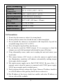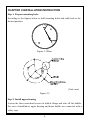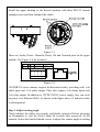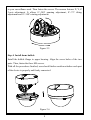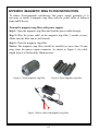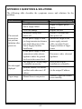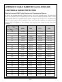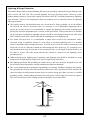
1
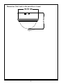
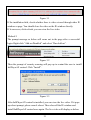
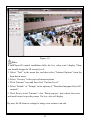
V6822IR-TA Series HD 2MP Vandal Resistant IR IP Minidome Camera with Auto Focus User Manual Notice Copyright Statement This manual may not be reproduced in any form or by any means to create any derivative such as translation, transformation, or adaptation without the prior written permission of Infinova. Infinova reserves the right to change this manual and the specifications without prior notice. The most recent product specifications and user documentation for all Infinova products are available on our web site www.infinova.com. Trademarks Infinova® is a trademark of Infinova. All other trademarks that may appear belong to their respective proprietors. FCC Warning The V6822IR-TA series HD 2MP IR IP minidome cameras comply with the FCC rules. Operation is subject to the following two conditions: This device will not cause harmful interference. This device must accept any interference received, including interference that may cause undesired operations. The V6822IR-TA series HD 2MP IR IP minidome cameras have been tested and found to comply with the limits for a Class A digital device, pursuant to the FCC rules. With these rules and regulations being obeyed to maintain the good working condition of device, the operation is not supposed to be affected by the external interruptions under certain circumstances. This device is electromagnetic, so all the installation and application processing along the device has to follow strictly to the manual or it may hamper the telecommunication around. Meanwhile, there is no guarantee that interference will not occur in a certain particular installation situation. Read this manual carefully before installation. This manual should be saved for future use. Important Safety Instructions and Warnings: Electronic devices must be kept away from water, fire or high magnetic radiation. Clean with a dry cloth. Provide adequate ventilation. Unplug the power supply when the device is not to be used for an extended period of time. Only use components and parts recommended by manufacturer. Position power source and related wires to assure to be kept away from ground and entrance. Refer to qualified personnel for all service matters. Save product packaging to ensure availability of proper shipping containers for future transportation. Indicate that the un-insulated components within the product may carry a voltage harmful to humans. Indicate operations that should be conducted in strict compliance with instructions and guidelines contained in this manual. Warning: To avoid risk of fire and electric shock, keep the product away from rain and moisture! CONTENTS Chapter I System Introduction............................................................................... 1 1.1 Product Description..........................................................................................1 1.2 Product Features...............................................................................................1 1.3 System Requirement ........................................................................................2 1.4 Product Model ..................................................................................................3 1.5 Specifications ...................................................................................................3 1.6 Precautions .......................................................................................................5 Chapter II Installation Instruction......................................................................... 6 Chapter III IE Browser Settings........................................................................... 10 3.1 Equipment Connection...................................................................................10 3.2 Software Installation ......................................................................................10 Chapter IV Basic Function Operation................................................................. 13 4.1 Live View .......................................................................................................13 4.2 System ............................................................................................................16 4.2.1 System Information...............................................................................16 4.2.2 Time Settings ........................................................................................17 4.2.3 Advanced Settings.................................................................................18 4.3 Network Settings ............................................................................................22 4.3.1 Network Settings...................................................................................22 4.3.2 FTP Settings..........................................................................................24 4.3.3 SMTP Settings ......................................................................................24 4.3.4 HTTPS Settings ....................................................................................25 4.3.5 802.1X Settings.....................................................................................25 4.3.6 QOS Settings.........................................................................................26 4.3.7 IGMP Settings.......................................................................................26 4.3.8 SIP Settings ...........................................................................................27 4.3.9 MDA Settings .......................................................................................28 4.3.10 DDNS Settings....................................................................................29 4.3.11 UPnP Settings......................................................................................29 4.4 Camera Settings..............................................................................................31 4.4.1 Basic Settings........................................................................................31 4.4.2 Exposure Settings .................................................................................32 4.4.3 Effect Settings.......................................................................................33 4.4.4 White Balance Settings.........................................................................35 4.4.5 Focus Settings ...................................................................................... 36 4.4.6 IR Settings............................................................................................ 40 4.4.7 Reset..................................................................................................... 41 4.5 Audio & Video Settings..................................................................................41 4.5.1 Video Settings ...................................................................................... 41 4.5.2 OSD...................................................................................................... 44 4.5.3 Privacy Mask ....................................................................................... 46 4.5.4 Motion Detection ................................................................................. 47 4.5.5 Shelter Alarm ....................................................................................... 48 4.5.6 Link Configure..................................................................................... 49 4.5.7 Storage Path ......................................................................................... 49 4.5.8 Audio Settings...................................................................................... 50 4.6 Alarm Settings ............................................................................................... 50 4.7 Record Management ..................................................................................... 52 4.7.1 Record Settings .................................................................................... 53 4.7.2 Replay .................................................................................................. 54 4.8 Account Settings............................................................................................ 57 4.9 System Log.................................................................................................... 59 Appendix I Magnetic Ring Filter Instruction ..................................................... 61 Appendix II Questions & Solutions...................................................................... 62 Appendix III Cable Diameter Calculation and Lightning & Surge Protection ..................................................................................................... 63 CHAPTER I SYSTEM INTRODUCTION 1.1 Product Description V6822IR-TA series HD 2MP IR IP minidome camera features 1/3" progressive scan CMOS sensor and built-in 3.0-9.0mm motorized zoom lens. With H.264 High profile/M-JPEG video compression format utilized, this series can output real-time images with the resolution up to 1920×1080@30fps. The camera supports three simultaneous video streams. It features bi-directional audio with G.711 compression. With the built-in motorized zoom lens, the camera can focus clear in several seconds when click the target on the web page. Low power consumption and a unique light control technology ensure a long IR illuminator service life. With Smart-IR technology, the camera effectively avoids the image overexposed and underexposed, and ensures natural color and more details. V6822IR-TA series minidome camera is the ideal choice for high-resolution surveillance under challenging lighting environments, including governments, financial institutions, telecommunications, schools, airports, factories, hotels, museums and city streets. 1.2 Product Features Infinova’s V6822IR-TA series camera has the following features and functions: 1/3" low light progressive scan CMOS sensor IR-Cut Removable (ICR) Filter for Day/Night switching Motorized zoom lens for Auxiliary Focus High-performance IR illuminators, 20m illumination distance Smart-IR technology, no image overexposure or underexposure Supports WDR function Onvif Profile S High-resolution image signal output: 1920×1080@30fps 1 Small bandwidth occupancy and high image quality With the maximum frame rate up to 30fps. Three Simultaneous Video Streams: Dual H.264 & Scalable M-JPEG Smooth dynamic video replay Supports anti-reflection function Up to four definable motion detection areas Up to four definable privacy mask areas Supports active video tampering Local Recording Supports storage with TF card Bi-directional audio, G.711 2 alarm inputs, 1 relay output Supports multiple ways to handle alarms, such as email sending, FTP upload and relay output Supports simultaneous multi-user access and parameter configuration via Web Server Compatible with Infinova’s V2216 and other digital video surveillance software, Provides standard SDK, easily integrated with other video surveillance software Supports public access Surface Mount, 3-axis adjustment With analog video debugging interface 1.3 System Requirement Configuration of the computer to display image and control the camera: CPU: Intel Pentium 4, 2.4 GHz or above RAM: 512 MB or greater Network Port: 100M Ethernet port Operating System: Microsoft Windows 7, Microsoft Windows XP IE browser version: Microsoft Internet Explorer 6.0 or above 2 1.4 Product Model This manual is for the following models: V6822IR-TA220SF HD 2.0 Megapixel IR IP minidome camera, Vandal-resistant, 3-axis, Day/night, 1/3 inch CMOS sensor, H.264/M-JPEG, 2.0 Mpx, 20m IR range, PoE/12VDC/24VAC, Surface mount, 3.0-9.0mm motorized zoom lens 1.5 Specifications Model V6822IR-TA Image Sensor 1/3" progressive scan CMOS Dynamic Range 72.4dB Lens F1.2, f=3.0-9.0mm Camera Angle Adjustment X (Panning): 0°~340°; Y (Tilting): 0°~72°; Z (Rotating): 0°~340° IR Wavelength 850nm IR Illumination Distance Day/Night Functionality 20m Sensitivity ICR Color mode: 0.05 lux @ F1.2 (30IRE, AGC ON); B/W mode: 0 lux @ F1.2 (IR ON) Exposure Scene mode, Manual mode, Shutter priority mode Shutter Auto/Manual (1/25s~1/8000s) White Balance Gain Control Auto/Manual/Incandescent light/Cool white fluorescent light/Sun light/Cloudy/Natrium light Auto/Manual 3 Noise Reduction 3D Video Compression H.264 High profile / M-JPEG Maximum Resolution 1920[email protected]/M-JPEG Major stream: 19201080, 12801024, 1280960, Optional Resolution 1280720, 1024768, 800600; Minor stream: 720576, 720480, 640480, 352288, 352240 Maximum Frame Rate Data Rate 30fps@19201080 Variable bit rate; Constant bit rate: 256Kbps ~ 10000Kbps Audio Compression: G.711-U; Audio 1 input (Linear level, Resistance: 1000 Ohm), 1 output (Linear level, Resistance: 600 Ohm) Motion Detection Up to 4 areas Privacy Mask Up to 4 masks Local Recording Available TF Card Storage Available, up to 32G card Upgrade Online Available Password Protection Available Alarm 2 alarm inputs, 1 relay output Network Port 1 RJ45 10/100M self-adaptive Ethernet port IPv4, IPv6, TCP, UDP, IGMP, DHCP, FTP, SNMP Applicable Protocols (V3), SMTP, NTP, RTP, RTSP, RTCP, HTTP, HTTPS, TSL, SSL, 802.1X, QoS, PPPoE, DNS, ARP, ICMP,UPNP, DDNS, Profile S Power Supply PoE IEEE 802.3af Class 3/12VDC/24VAC 4 Power Consumption <9W Operating Temperature 14° F ~ 122° F (-10° C ~ 50° C) Storage Temperature -4° F ~ 140° F (-20° C ~ 60° C) Operating Humidity 0~90% RH (non-condensing) Unit Dimensions (H×Ø) Unit Weight 1.87 lbs. (0.85kg) Shipping Weight 2.54 lbs. (1.15kg) Impact Resistance IK10 4.07"×5.20" (103.3mm × 132mm) 1.6 Precautions 1. Do not drop the camera or subject it to strong knock. 2. Do not point the camera lens toward the sun or other strong light. 3. Do not install the camera in environment with temperature beyond the acceptable range (from -10°C to 50°C). 4. Never let liquid of any kind flow into this unit. 5. Do not directly touch the CMOS element. If it is necessary to clean the element, use a soft cloth moistened with alcohol to wipe off the dust. 6. If any abnormality occurs, make sure to unplug the unit and contact your local dealer. 7. This camera features AGC circuit, so when the camera is applied under low illumination, sensitivity will enhance automatically, making images look rough, which is normal. 8. The camera power supply can be PoE/12VDC/24VAC. Be sure of the +/terminal correct when the camera is connected with 12VDC power supply. 24VAC power supply must be isolated power. 9. Firstly perform network settings after login. Gateway IP address should be set to the IP address of the gateway that the device connects to. 10. The IP address of the device should not conflict with other IP address; or else no video will be available. 5 CHAPTER II INSTALLATION INSTRUCTION Step 1: Prepare mounting holes According to the figures below to drill mounting holes and cable hole at the desired position. Figure 2-1 Base (Unit: mm) Figure 2-2 Step 2: Install upper housing Loosen the three mum-head screws in bubble flange and take off the bubble. For ease of installation, upper housing and dome bubble are connected with a safety rope. 6 Install the upper housing to the desired position with three M4×25 conical tapping screws and then arranged the cables. Figure 2-3 There are Audio, Power, Alarm In, Relay Out and Network ports in the upper module. (See Figure 2-4 for location.) Figure 2-4 V6822IR-TA series cameras support bi-directional audio, providing with 1-ch audio input and 1-ch audio output. They also support 2-ch alarm inputs and 1-ch relay output. In addition to 12VDC/24VAC power supply, they can work on power over Ethernet (PoE). As shown in the figure above, G indicates audio or alarm ground. Step 3: Adjust viewing angle Check whether the cables are properly and firmly connected before powering on. Remember to visit the device about 60 seconds after power-on. At the moment, loosen the knurled thumb screws to adjust the camera angle according 7 to your surveillance need. Then fasten the screws. The camera features X, Y, Z 3-axis adjustment. It allows 0°~340° panning adjustment, 0°~72° tilting adjustment and 0°~340° rotating adjustment. Figure 2-5 Step 4: Install dome bubble Install the bubble flange to upper housing. Align the screw holes of the two parts. Then, fasten the three M4 screws. With all the procedures finished, user should further confirm whether each part of the device is properly and firmly connected. Figure 2-6 8 Dimensions (Unit: inch, in the parentheses is mm) Figure 2-7 9 CHAPTER III IE BROWSER SETTINGS When view the video, the user need to adjust the IE browser of the monitor or other video devices, and set proper system function based on the following instructions: Support IE browser version: Internet Explorer 6.0 or above; Must install InfiPlayerAX control and equip with Directx 9.0c. 3.1 Equipment Connection V6822IR-TA series camera can be directly connected to a computer, or connected to a network. Note: Check whether the connection is tight or not before power-on. 3.2 Software Installation The installation procedures of V6822IR-TA series camera image software are listed as follows: (1) Login First, start IE browser and enter IP address. Enter user name and password in the pop-up login interface. The default IP address is http://192.168.1.100; the default subnet mask is 255.255.255.0 and the default gateway IP address is 192.168.1.254. For normal access, correctly set local IP parameters before system login. Do log in the system with the default super user for the first time to run the software. The default Super User is admin (password: admin). (2) Install and run Control There are two ways to install control. Method 1: The prompt message as below will come out in live view window after a successful login. Click the link to run, or store the exe file, then run it. 10 Figure 3-1 If the installation fails, check whether there is video viewed through other IE window or page. You should close the video or the IE window directly. If it successes, click refresh, you can view the live video. Method 2: The prompt message as below will come out in the page after a successful login. Right click “Add-on Disabled” and select “Run Add-on”. Figure 3-2 Then the prompt of security warning will pop up to remind the user to install InfiPlayerAX control. Click “Install”. Figure 3-3 After InfiPlayerAX control is installed, you can view the live video. If it pops up reboot prompt, please cancel reboot. Then close all the IE window and install InfiPlayerAX control once again. The live video will display as below: 11 Figure 3-4 Note: If InfiPlayerAX control installation falls, the live video won’t display. Then, you should change the IE security level. 1. Select “Tool” in the menu bar, and then select “Internet Options” from the drop-down menu. 2. Select “Security” in the pop-up Internet options. 3. Click “Internet” icon and then click “Custom Level”. 4. Select “Enable” or “Prompt” in the options of “Download unsigned ActiveX controls”. 5. Click Privacy in the “Internet”, clear “Block pop-ups”, then redraw the screen and install control as per the prompt. The live video will display. By now, the IE browser setting for image view comes to an end. 12 CHAPTER IV BASIC FUNCTION OPERATION This chapter mainly introduces camera’s settings and operation. 4.1 Live View Start IE browser after the server is powered on for about 75 seconds, and then enter IP address, such as http://192.168.1.100 (default), in the address field. Note: The default subnet mask is 255.255.255.0 and the default gateway IP address is 192.168.1.254. For normal access, please correctly set local IP parameters before system login. The login interface is displayed as shown in figure below in English operating system. Figure 4-1 User Login Do log in the system with the default super user for the first time to run the software. The default Super User is admin (password: admin). Input the correct user name and password and then click “OK” button to log. After login is successful, the following interface will display: 13 Figure 4-2 H.264 Live View V6822IR-TA series camera supports H.264 and M-JPEG video compression formats. After successful login, it enters H.264 major stream live video interface. Users can also select H.264 minor stream or MJPEG from the drop-down list of stream type. In the H.264 major or minor stream type, users can do recording, snap shooting, audio in/out, motion detection and privacy mask settings. Over browsing videos, users can also select a proper video scale. Play mode: live or fluid for option. Click the button to snapshoot and to enter the storage path. Default: C:\InfiPlayerAX\Picture. V6822IR-TA series supports local recording. Click the recording button start recording; when the button changes to , click it to stop recording. During local recording, “REC” appears on the video screen. Click the button enter the recording storage path. Default: C:\InfiPlayerAX\ Video. 14 to to Users can set the snapshooting and recording storage path in the audio and video settings interface. Indicate audio input/output disabled. Click the buttons to enable audio input/output and then the buttons will be shown as . Indicate that the motion detection and privacy mask functions are disabled. Click the buttons to enable them and then the buttons will be shown as . Note: only when motion detection or privacy mask is enabled, you can set the corresponding function in Audio & Video Settings, refer to Section 4.5.3 or 4.5.4 for details. Note: the login web page language should be set to the same as that of PC’s operating system. Click the option tab “Setting” to enter the system setting interface. Figure 4-3 Settings Interface 15 With the help of navigation menu on the left, Super user can perform the following operations: Basic Information View, Time Settings and Advanced Settings, Network Settings, Camera Settings (including Basic Set, Effect Set, White Balance, Focus, IR set, Reset), Audio & Video Settings, Alarm Settings, Record Management, Account Settings (Add/Delete User, Change Password), Log, etc. Note: The following instructions are used for the super user. 4.2 System Click the navigation bar “System” and it displays the following three option tabs: System, Time and Advanced, as shown in Figure 4-3. 4.2.1 System Information The initial interface of System Settings displays related system information, such as basic system information, network settings, NTP settings, alarm settings, H.264/MJPEG video settings, etc. 16 4.2.2 Time Settings Figure 4-4 “Time” Settings Time Zone Settings Time Zone: Select the desired time zone in the scroll box, and then click “Save” to save it. There are 33 time zones for your selection. GMT+8:00 is Beijing time. If Daylight Saving Time is applied in your region, please enable daylight saving time. After settings completed, please click the button “Save”. NTP Settings Set the NTP server’s IP address, test NTP server’s status, and set parameters of Sync with NTP, including enable/disable Sync with NTP, Sync time and Sync interval. After completed, please click the button “Save”. Sync now There are two sync modes: local sync and NTP sync. Local Sync means the system time is consistent with that of local PC. In the 17 NTP Sync mode, the system will automatically adjust time to the same as that of NTP Server. 4.2.3 Advanced Settings Figure 4-5 “Advanced” Settings Software Update Free software update is provided for V6822IR-TA series camera, and this update service can reduce system maintenance budget. Confirm the requirement submitted by user, we will provide the latest software for download, and help user to update the V6822IR-TA series camera. Follow the steps below to update software: Click “Browse” button on the interface and the file selection dialog box will pop up. 18 Figure 4-6 Select update file, and press “Open” button. The selected update file will be displayed in the Software Update box. After that, click “Submit” button to update software, the following information will appear: Figure 4-7 Click “Yes” button, run the program to finish the update. The response time is due to the program type. You may wait a long time for some program. Do not power off during the update process. Power-off will make update fail, even damage the original program or unable to update again. 19 After update successfully, it needs to reboot the system. There is time prompt in the web page during reboot. After reboot, it will skip to new web page to run new program. Note: Available only for the super user. Factory Settings V6822IR-TA series camera provides online reset function, which greatly facilitates reset adjustment. Select “Keep current IP unchanged”, click “Reset” button and the system will pop up a message as below: Figure 4-8 Click “OK”, all the parameters (excluding IP address) will be reset to the factory default settings. If “Keep current IP unchanged” is unselected, the IP address will be reset to the factory default settings. There is time prompt in the web page during reset. After reset, it will skip to new web page. If current IP unchanged, you can access web page directly. If IP address resets to 192.168.1.100, you can’t access web page. Then, you have to set PC’s IP address to 192.168.1 section, such as 192.168.1.25. After that, access web page to change camera’s IP address and save, PC’s IP address will restore to the corresponding section. 20 Note: 1. To avoid error happens, the operation of online reset function should be performed under qualified personnel’s guide. 2. Default IP address is 192.168.1.100, and default subnet mask is 255.255.255.0. 3. Do not power off during reset, or else the reset will fail. Online Reboot Click “Reboot” button, the dialog box “This operation will take 75 seconds, are you sure to continue?”pop up. Click “OK” and the system will restart. There is time prompt in the web page during reboot. After reboot, it will skip to new web page. Note: Available only for the super user. 21 4.3 Network Settings Click “Network” in the navigation bar, and the following interface will display: Figure 4-9 Network Settings 11 options tabs are available: Network, FTP, SMTP, HTTPS, 802.1X, QOS, IGMP, SIP, MDA, DDNS and UPnP. 4.3.1 Network Settings IP mode: support both IPv4 and IPv6 modes. Network parameters are slightly different under different IP modes. 22 Figure 4-10 Network Settings Under IPv4 mode, users can enable or disable DHCP. When it is disabled, users can set Unit IP address, Subnet mask, Gateway and DNS server IP address manually. Users can also enable/disable PPPoE in this interface. If enabled, users can set the user name and password. V6822IR-TA series camera supports heartbeat function. In SNMP settings, set and save the heartbeat sever IP address and Heartbeat interval, and then the heartbeat package will be sent to the server or client, which greatly facilitates the server or client to know about the camera’s network status. 23 4.3.2 FTP Settings Figure 4-11 FTP Settings V6822IR-TA series camera has the function of alarm associated with FTP upload (alarm triggered image snapshot). Configure server IP, user name and password in the FTP settings and activate FTP handling way in alarm settings, then alarm triggered images FTP upload can be achieved. 4.3.3 SMTP Settings Figure 4-12 SMTP Settings User needs to set mail server, recipient, etc in SMTP settings interface. Server IP: Set mail server address. From: Set sender’s mail address. To: Mail address of recipient. 24 CC: Mail address of the person copy to. Authentication: Enable or disable authentication function. This function User name: Sender’s name, it can be set according user’s needs. Password: Set sender’s password. should be set according to authentication requirements of mail server. Note: there is no limit for Sender’s name and password settings. After setting, click “Set” Save to take effect. If user selects “mail” in “Alarm Settings” interface, system will send mails according to SMTP settings. 4.3.4 HTTPS Settings Figure 4-13 HTTPS Settings V6822IR-TA series camera supports HTTPS protocol. You can import the CA certificate in the interface. 4.3.5 802.1X Settings Figure 4-14 802.1X Settings 25 V6822IR-TA series camera supports 802.1X protocol. You have to enable 802.1X authentication when needed. Then, select an EAP method and enter the user name and password. 4.3.6 QOS Settings Figure 4-15 QOS Settings There are 4 network Qos modes to be selected: (1) Normal Service (2) Max Reliability (3) Max Throughput (4) Min Delay Recommend: Normal Service. 4.3.7 IGMP Settings Figure 4-16 IGMP Settings 26 V6822IR-TA series camera supports multicast function. In the IGMP interface, users can select the stream type and set the state, multicast IP address and RTP port. 4.3.8 SIP Settings Figure 4-17 SIP Settings SIP Server: to configure SIP server for device; SIP Server IP: the IP address of SIP server; Port: the port number of SIP server; Server ID: the ID of SIP server; Device ID: the device ID used for registration with SIP server; Alarm ID: the ID registered for device alarm; Register Interval: the interval for re-registration of device in seconds; Heat Beat Interval: the interval to send heat beat information by the device in 27 seconds; After configuration completed, click Save and the device sends a registration request to the server. Position Information: the mounting information or instruction for device. Longitude: the longitude of mounting position, as precise to two places of decimal; Latitude: the latitude of mounting position, as precise to two places of decimal. 4.3.9 MDA Settings Figure 4-18 MDA Settings In MDA settings interface, you can set the Sever which the motion detection alarm uploads to. State: disable or enable motion detection alarm upload. When it’s on, you can set camera name, user name, password, server IP and Port number. After setting completed, click “Save” button to take effect. 28 4.3.10 DDNS Settings Figure 4-19 DDNS Settings Dynamic Domain Name System (DDNS) synchronizes the host name and dynamic IP address continuously. Users don’t have to memorize the dynamic IP address, but enter the dynamic domain name to connect the IP camera. DDNS needs a PC with fixed IP address on the Internet to run the dynamic domain name server. Operation: select DDNS type in Enable option, enter the IP address of the DDNS server into the address bar, and configure domain name, user name, password, and update time and then save the settings. Open the IE browser, and enter the domain name to go to the query page of the device. 4.3.11 UPnP Settings Create mapping between private network and the Internet via UPNP protocol. Select UpnP option and enter the configuration page. The added mapping list appears on the page. 29 Figure 4-20 UPnP Settings In “Operation” column, means to delete; information. Click Add button to add the mapping. Figure 4-21 30 means to edit user 4.4 Camera Settings Click “Camera” in the navigation bar to enter the interface shown as below: Figure 4-22 Basic Settings 4.4.1 Basic Settings You can set the following parameters: Flicker frequency: 50Hz or 60Hz. CVBS: it automatically changes with the flicker frequency. (Note: analog video is closed after MJPEG stream is enabled. To enable analog video, please close MJPEG stream.) 31 Enable or disable backlight compensation or digital WDR. Contrast Enhance: 1~6 levels match with 6 kinds of Gamma curve separately. If it is set to Auto, the system will adjust automatically. 4.4.2 Exposure Settings Figure 4-23 Exposure Settings Exposure set, auto aperture, scene, AGC, shutter speed and manual AGC can also be set in this interface. 32 Exposure Set: Manual, Scene and Shutter Priority available. In Scene mode, indoor or outdoor can be selected and AGC can be set (maximum 64X); if set to Manual mode, shutter speed can be set from 1/25s to 1/8000s and manual AGC can be set to 1X to 64X, yet the scene and AGC are nonadjustable; if set to Shutter Priority mode, the shutter speed and AGC can be set. Auto aperture: to enable or disable auto iris. AE target: set AE target level. It can adjust video brightness via AE target setup. 4.4.3 Effect Settings In the Effect Settings interface, users can adjust the brightness, sharpness, hue, contrast, saturation and 3D denoise in two ways: General or Mode, as shown in the figure below: Figure 4-24 Effect Set - General 33 Drag the slider to adjust the brightness, sharpness, hue, contrast, saturation and 3D denoise. Figure 4-25 Effect Set - Mode The camera supports 6 video effect modes. Users can set and save Name, IR mode and Scene parameters for each mode. Click “Factoryset” to restore it to default settings. The camera provides 7 Scene modes: Normal, Anti Fog, Motion, Entrance, 34 Natrium, Sharpen, USrMode. Each mode matches with a group of parameters, such as brightness, sharpness, hue, contrast, saturation and 3D denoise. In the Mode call, users can set effect mode call status and call period. 4.4.4 White Balance Settings Figure 4-26 White Balance Settings The camera has rich white balance modes, including Auto, Manual, Incandescent light, Cool white fluorescent light, Sun light, Cloudy and Natrium light. If set to manual mode, you can set the red gain and blue gain. 35 4.4.5 Focus Settings Figure 4-27 Focus Settings V6822IR-TA series camera is built-in motorized zoom lens for remote focal length adjustment. Click “Focus” in camera settings interface to enter focus settings. In this page, you can select focus mode, zoom/focus and call focus limit. Auto focus: In auto focus mode, the interface is shown as above figure. Click button to focus wide; click button to focus tele. In this process, the interface is shown as figure below. 36 Figure 4-28 After focus finished, it will return to the interface as shown in Figure 4-23. The focus time will be different as the lens original positions are different. Focus process lasts 15s at most. You can stop focus by clicking Stop button during focusing. Left-click one section, the frame of this section will turn to green and the camera will automatically focus for this area, shown as below: 37 Figure 4-29 Manual focus: click Manual focus to enter the interface as below. 38 Figure 4-30 Click Click to focus wide/zoom tele. to focus near/focus far. Focus Limit: the camera can call focus limit. There are 5 options: Near, Middle, Far, User set 1, User set 2. The effects for Near, Middle and Far are default; but User set 1 and User set 2 can be specified by users. Reset: if the camera cannot focus clear by auto focus, click Reset button to restart the motor. 39 4.4.6 IR Settings Figure 4-31 IR mode: set IR illuminators working mode. Options: Off, On, Auto (turn on or off as per ambient light). Switch time: in auto mode, the response time for day/night switch. Power set: the adjusting mode of illuminators’ power consumption. Options: Auto, Manual. In auto mode, adjust illuminators’ brightness as per ambient light. In manual mode, adjust the brightness by moving the slider in the page. Rectify focus: if select it, camera will focus automatically when the video switches between color mode and B/W mode. 40 4.4.7 Reset In the interface, you can restore all the Camera Settings parameters to the factory default settings. 4.5 Audio & Video Settings Click the button Audio & Video in the navigation bar to display the following interface. Figure 4-32 Video Settings Click the related option tab to enter the setting interface. 4.5.1 Video Settings Users can set the video parameters in the format of H.264 major or minor stream and MJPEG stream, such as resolution, frame rate and IP rate. 41 Resolution: For H.264 major stream, the resolution comes up to 19201080, with 12801024, 1280960, 1280720, 1024768, 800600 optional. For H.264 minor stream, resolution comes to 720576, 720480, 640480, 352288, 352240 and closed. For MJPEG stream, resolution comes to 19201080, 12801024, 1280720, 720480 and closed Frame Rate: the number of compressed frames produced by camera per second. The bigger the frame is, the better the image continuity will be, but the CPU performance is lowered. The smaller the frame is, the worse the image continuity will be, but the CPU could handle more events. The maximum frame rate for H.264 is 30fps. The maximum frame rate for MJPEG is 10fps. Note: the video settings of H.264 major/minor stream are linkage with that of MJPEG stream. If H.264 major stream is set to 1080P/30fps, minor stream closed, MJPEG is only able to set to1080P/4fps. If H.264 major stream is set to 1080P/25fps, minor stream closed, MJPEG frame is able to set to 10fps. Do operate according to the prompt on the page. GOV number: GOV number means the ratio of I frame to P frame in compressed video images. The bigger the value is, the less the data quantity is and the less network resource occupancy. Max. GOV number can be set to 60. Bit Rate: There are 2 modes: variable rate (vbr) and constant rate (cbr). The variable rate can adjust the bandwidth that it occupies automatically 42 according to the complexity of image, because the complexity of real video sequence keeps changing, details, speed, etc, and the variable rate setting mode can be used to choose how much bandwidth should be used. If the video gets more details and moving fast, then it takes up more bandwidth to transmit, and reversely it occupies less bandwidth. When the setting goes with constant bit rate, then the image is transmitted under a constant bandwidth. Bit Rate Upper Limit: You have to set the upper limit of bit rate if “vbr” is selected; the stream size will be fixed if “cbr” is selected and the stream size is defined in the “Bit Rate Upper Limit”. For major stream, the bit rate upper limit can be 1000kbps~10000kbps; for minor stream, the bit rate upper limit can be 256Kbps~ 2000Kbps. Image Quality: it can be set under MJPEG stream. Options: Highest, High, Average, Low and Lowest. The higher the image quality is, the more bandwidth it will occupy. 43 4.5.2 OSD Figure 4-33 OSD Mode 1 OSD settings include: Text OSD and Date OSD. The camera supports two OSD modes: Mode 1, Mode 2. You can switch the mode only if Text 2 is on. Only if Text 1, Text 2 and Date OSD are set to “On”, you can set the text content and the display position of text and date. Context: Enter the text content in the box of Context, which allows up to 40 characters (lower/upper case letters and 0~9). X-axis &Y-axis: The title axis location. Both X-axis and Y-axis can be any of whole numbers from 0 to 99. Font Size: Set the font size to be displayed. The bigger the value is, the larger the font size is. Default as: 3. 44 After all settings finished, click “Save” button to display OSD on the video. To cancel OSD, set it to “Off” and then click the button “Save”. See the figure for OSD Mode 2: Figure 4-34 OSD Mode 2 Only if Text 1, Text 2 and Date OSD are set to “On”, you can set the text content and the display position of text and date. Context: Enter the text content in the box of Context. Text 2 supports five-row display and each row allows up to 40 characters (lower/upper case letters and 0~9). X-axis &Y-axis: The title axis location. Both X-axis and Y-axis can be any of whole numbers from 0 to 99. Font Size: Set the font size to be displayed. The bigger the value is, the larger the font size is. Default as: 3. After all settings finished, click “Save” button to display OSD on the video. To cancel OSD, set it to “Off” and then click the button “Save”. 45 4.5.3 Privacy Mask V6822IR-TA series camera supports 4 privacy masks. If there is certain location within the surveillance area where operators are not allowed to see, and thus, Privacy Mask can be applied. System covers and shields the sensitive area via Privacy Mask setting, to avoid operators observing certain sensitive locations on monitor. Note: do turn on privacy mask function in Live View interface before privacy mask setting (see Section 4.1). Figure 4-35 Privacy Mask Settings How to set the privacy masks: Tick the box of motion detection area number. Click the button “Draw” with the mouse, press the left mouse button and drag on the video till a blue frame displays on the screen. Then, click the button “Save” with the left mouse 46 button and the blue frame changes into black which indicates a successful setting. To cancel a privacy mask, just cancel the box ticking. 4.5.4 Motion Detection Figure 4-36 Motion Detection Settings V6822IR-TA series camera support motion detection. Users can easily set the motion detection areas (up to 4) with the mouse. Note: do turn on motion detection function in Live View interface before motion detection setting. Tick the box of Zone number to be set. If the motion detection area has been set, a blue frame will be displayed on the screen. 47 How to set the motion detection area: Tick the box of motion detection area number. Click the button “Draw” with the mouse, and press the left mouse button and drag on the video till a blue frame displays on the screen. Then, click the button “Save” with the left mouse button and the blue frame changes into green which indicates successful setting. Besides, you can set the area name and sensitivity. To cancel a motion detection area, just cancel the box ticking. 4.5.5 Shelter Alarm Figure 4-37 V6822IR-TA series camera supports shelter alarm function. Users can easily set the shelter alarm areas with the mouse. At first, enable shelter alarm. Click the button “Draw” with the mouse, press the left mouse button and drag on the video till a blue frame displays on the 48 screen. Then, click the button “Save” with the left mouse button and the blue frame changes into green which indicates a successful setting. Besides, you can set the area name and sensitivity. It will trigger alarm when the video within the area is shielded. Refer to Section 4.6 for alarm contact details. 4.5.6 Link Configure Figure 4-38 For each stream, the total of 90 port and RTSP port is 5. In this interface, you can set the video numbers of 90 port and RTSP port. The default setting is visit 2-ch major stream, 2-ch minor stream and 2-ch MJPEG video via 90 port and visit 3-ch major stream, 3-ch minor stream and 3-ch MJPEG video via RTSP port. 4.5.7 Storage Path You can set the photo saving path and recording saving path in the following interface. Figure 4-39 Storage Path Default photo saving path: C:\InfiPlayerAX\Picture. 49 Default video saving path: C:\InfiPlayerAX\ Video. Photo and video formats can also be set. The default photo format is .jpg and the default video format is .avi. To change the saving path, click the button “Browse” and select the path from the popup dialog box. 4.5.8 Audio Settings Figure 4-40 Audio Settings Sample Rate: 8K. Format: G.711-U. 4.6 Alarm Settings Click “Alarm” in the navigation bar to display the following Alarm Settings interface: 50 Figure 4-41 Alarm Settings Alarm configuration I/O In 1, I/O In 2: Settable 2-channel alarm inputs. Each alarm input has 2 modes: Grounded Circuit or Open Circuit. Alarm out contact: used to set sending way of alarm. Local Contact: I/O out is triggered by I/O alarm in, motion detection alarm, shelter alarm, SD card out, network link down or IP address conflict. Default: Local Contact. Net Contact: I/O out is controlled by the surveillance management software. Note: This function needs to be supported by digital video surveillance management software like V2216. If Net Contact is selected, users have to set 51 Alarm Server IP the same as the IP address of V2216-CMS server. After related setting to V2216 finished, users can remotely control the relay via V2216 software. For detailed information, please refer to V2216 manual. Alarm Server IP: used to set the IP address of alarm server. If alarm occurs, it will inform the alarm server. Alarm out contact Users can set the relevant alarm response ways for I/O alarm in, motion detection alarm, shelter alarm, SD card out, network link down or IP address conflict. Options: Alarm out 1 (if Net Contact is selected, Alarm output 1 on the web page is unavailable), SD card, Mail, FTP and Audio. After setting completed, click “Save” button to take effect. Note: when “FTP” or “Mail” is selected, you need to set FTP or SMTP parameters in Network Settings, refer to Section 4.3.2 or Section 4.3.3 for details. Alarm schedule V6822IR-TA series camera can set the effective alarm schedule. Select the alarm period (if Sunday is selected, alarm will be enabled during the set period of each Sunday; if Everyday is selected, alarm will be enabled during the set period of everyday), and then, set the time period. Enter the start time and end time in the 24-hour format. The end time must be larger than the start time. 4.7 Record Management Click “Record” in the navigation bar to display the following settings interface: 52 Figure 4-42 In the record interface, you can configure settings and replay. 4.7.1 Record Settings Recording video type: Select the type of videos to record, major stream or minor stream. SD card when full: Overwrite or Stop. Overwrite means newly recorded videos automatically overwrite the previous videos when the SD card is full; Stop means recording stops when the SD card is full. Recording mode: Alarm triggered, Always, Close. If Alarm Triggered is selected, also with SD card selected under alarm out contact in the alarm interface (refer to 4.6), recording is automatically triggered when alarm occurs. You can view the total space, used space and state of SD card and also format it. To remove SD Card when it is being used, please click “Reject”. 53 4.7.2 Replay Figure 4-43 Replay Video Search: set the start and end time, and then click the search button. All videos recorded during this period of time will display in the list. 54 Figure 4-44 Searching Videos Replay: to replay a video, double click a file in the list with the mouse or select a file and then press the “Play” button . During playing, click or to pause or stop playing. Click the button on the right of video window, the right window will disappear, show as below: 55 Figure 4-45 Click the button , the interface will restore. Download: You can download the videos stored in the SD card to your PC. Select the file from the video list (also you can select multiple files simultaneously using the key “Ctrl” or “Shift”), and then click the button “Download” to enter the downloading interface. Figure 4-46 Downloading Videos 56 Save to: Set the path to save the downloaded files. If resetting required, click the button “Browse”. AVI/H.264 drop-down list box: select the downloaded file attribute. In the download list, file total size, status and process will display. Click the button “Start”, and then the files in the list will be downloaded in order. The process shows 100% after downloading is finished. Click the button “Open” to enter download content. 4.8 Account Settings The default super user is admin (password: admin). Super user can add, delete common user, and change the password of common users. Super user cannot change his own password. A maximum of 7 common users are supported. Detailed instruction about how to add and delete user are addressed below. Click the Account option tab in the Settings interface, the following account information will display. The “Num” item shows the current user number. In “Property” column, stands for super user; “Operation” column, means to delete; stands for common user. In means to edit user information. See figure below: Figure 4-47 Account Settings 1. Add Users (1) Click “ ”, enter the interface of “Add a User”. 57 Figure 4-48 Add a User (2) Enter the desired User Name and Password (Note: User name and password shall include letter, number and underline only. No special character is allowed. The string length of user name is legal between 1 and 30 characters and that of password is between 5 and 20 characters.) (3) Click “OK” button. If the setting is successful, the new user name will appear in the account list. Take new user “user1” as an example: Figure 4-49 2. Delete Users In the “Account setting” interface, click button of the “Operation” item to delete user. The following dialog box will display: Figure 4-50 58 Click “OK” button, the selected user would be deleted and the account list would be automatically updated. 3. User Password Change Click button in the account list, the dialog box of Edit User Information will pop up: Figure 4-51 Input the old password, enter the desired new password for twice and then click “OK” button, the following picture will appear: Figure 4-52 4.9 System Log Click the “Log” option tab, the date, time and log information will appear on the right of the screen. 59 Figure 4-53 It can display 30 logs on a page. The user can turn over the pages or skip to the desired page by clicking the below arrows. Click “Delete logs”, a prompt will come out. Then, click “Yes” to clear logs. 60 APPENDIX I MAGNETIC RING FILTER INSTRUCTION To reduce electromagnetic interference that power supply generates, it is necessary to install a magnetic ring filter with the power cable of Infinova front-end IP device. To install a magnetic ring filter with power supply: Step 1: Open the magnetic ring filter and lead the power cable through. Step 2: Wire the power cable on the magnetic ring filter 3 rounds or more (Make sure the filter can be well closed). Step 3: Close the magnetic ring filter. Notice: The magnetic ring filter should be installed no more than 50 mm away from the power output connector. As shown in Figure 3, the cable length from A to B should be 50mm at most. Figure 1 Closed magnetic ring filter Figure 2 Open magnetic ring filter Figure 3 Power cable with magnetic ring filter 61 APPENDIX II QUESTIONS & SOLUTIONS The following table describes the symptoms causes and solutions for the problems. Symptoms Possible Causes Wrong power connection Power supply failure The network camera does not perform initiation after power-on No video signal displayed Vague image PCB fuse damage Immediate startup after power-off If PoE power supply is used, too long transmission distance may make the power of the Power Supply Switcher insufficient. If PoE power supply is used, connection to other electric appliance makes the ground level not in the correct level. The plug-in for viewing image is installed incorrectly. Solutions Reconnect power cable Repair or replace power supply Replace the fuse Restart 10 seconds later after power-off Shorten the length of the power supply network cable, or replace Power Supply Switcher of larger power Disconnect other electrical appliance. Refer to the Plug-in Installation to reinstall it. Network camera’s IP address conflicts with other user’s IP address Set the unique IP address Manual focus is not precise Manually adjust the camera focus carefully. 62 APPENDIX III CABLE DIAMETER CALCULATION AND LIGHTNING & SURGE PROTECTION Relation between 24VAC Cable Diameter and Transmission Distance In general, the maximum allowable voltage loss rate is 10% for AC-powered devices. The table below shows the relationship between transmission power and maximum transmission distance under a certain specified cable diameter, on condition that the 24VAC voltage loss rate is below 10%. According to the table, if a device rated at 50W is installed 17-meter away from the transformer, the minimum cable diameter shall be 0.8000mm. A lower diameter value tends to cause voltage loss and even system instability. Diameter (mm) Distance (ft / m) Power (W) 0.8000 1.000 1.250 2.000 1811 (551) 10 283 (86) 451 (137) 716 (218) 20 141 (42) 225 (68) 358 (109) 905 (275) 30 94 (28) 150 (45) 238 (72) 603 (183) 40 70 (21) 112 (34) 179 (54) 452 (137) 50 56 (17) 90 (27) 143 (43) 362 (110) 60 47 (14) 75 (22) 119 (36) 301 (91) 70 40 (12) 64 (19) 102 (31) 258 (78) 80 35 (10) 56 (17) 89 (27) 226 (68) 90 31 (9) 50 (15) 79 (24) 201 (61) 100 28 (8) 45 (13) 71 (21) 181 (55) 110 25 (7) 41 (12) 65 (19) 164 (49) 120 23 (7) 37 (11) 59 (17) 150 (45) 130 21 (6) 34 (10) 55 (16) 139 (42) 140 20 (6) 32 (9) 51 (15) 129 (39) 150 18 (5) 30 (9) 47 (14) 120 (36) 160 17 (5) 28 (8) 44 (13) 113 (34) 170 16 (4) 26 (7) 42 (12) 106 (32) 180 15 (4) 25 (7) 39 (11) 100 (30) 190 14 (4) 23 (7) 37 (11) 95 (28) 200 14 (4) 22 (6) 35 (10) 90 (27) 63 Lightning & Surge Protection The product adopts multi-level anti-lightning and anti-surge technology integrated with gas discharge tube, power resistor and TVS tube. The powerful lightning and surge protection barrier effectively avoids product damage caused by various pulse signals with power below 4kV, including instantaneous lightning, surge and static. However, for complicated outdoor environment, refer to instruction below for lightning and surge protection: The product features with dedicated earth wire, which must be firmly grounded. As for surveillance sites beyond the effective protection scope, it’s necessary to erect independent lightening rods to protect the security devices. It’s recommended to separate the lightning rod from the mounting pole, placing the rod on an independent pole, as shown in the figure below. If the product has to be installed on the same pole or pedestal for lightning rod, there should be strict insulation between the video cable BNC terminal, power cable, control cable and the standing pole of the lightning rod. For suburb and rural areas, it’s recommended to adopt direct burial for the transmission cables. Overhead wiring is prohibited, because it’s more likely to encounter lightning strike. Use shielded cables or thread the cables through metal tubes for burial, thus to ensure the electric connection to the metal tube. In case it’s difficult to thread the cable through the tube all the way, it’s acceptable to use tube-threaded cables only at both ends of the transmission line, yet the length in burial should be no less than 15 meters. The cable sheath and the tube should be connected to the lightning -proof grounding device. Additional high-power lightning-proof equipment and lightning rods should be installed for strong thunderstorm or high induced voltage areas (such as high-voltage substation). The lightning protection and grounding for outdoor devices and wires should be designed in line with the actual protection requirement, national standards and industrial standards. The system should perform equipotential grounding by streaming, shielding, clamping and earthing. The grounding device must meet anti-interference and electric safety requirements. There should be no short-circuiting or hybrid junction between the device and the strong grid. Make sure there’s a reliable grounding system, with grounding resistance below 4Ω (below 10Ω for high soil resistivity regions). The cross-sectional area of the earthing conductor should be no less than 25mm². LPZOA 30° LPZOB 30° Lightning rod Front device for surveillance system Mounting pole for front device Separated layout for the lightning rod and the standing pole 64 Infinova 51 Stouts Lane, Monmouth Junction, NJ 08852, U.S.A. Tel: 1-888-685-2002 (USA only) 1-732-355-9100 Fax: 1-732-355-9101 [email protected] V1.3 1409