1
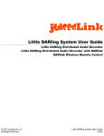
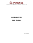
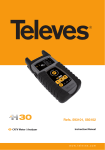
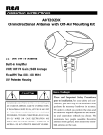
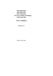
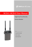
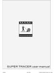
Instruction Manual
TL-EMS 8x1 RF Switch
( 8 Inputs x 1 Output, with RF Remote Control)
RF Switch
TL-EMS-8x1
RF Remote Controls (Tx)
CMD-HHLR
RF Receiver (Rx)
TL-RX-315
Control Cable
9VDC
AC Adapter
110/220 VAC
TL-EMS 8x1 Instructions
* Please read all instructions before installing and operating.
* Save this Instruction manual.
* Record ID: # 0123 for remote control Transmitter (CMD-HHLR-315)
Additional Tx must
have ID # 0123 to control this particular switch (see Operations) .
* Limitation: the Switch will not operate properly if either Tx and Rx are located behind RF
shielded obstruction.
Contents:
2. General Description TL-EMS-8x1............................................................. p.2
3. Switch Package Contents. ................................................................. p.3
4. Installation Guide and Operations Notes ............................................. p.4
5. Hookup and Test ................................................................................... P.5
Tin Lee Electronics Ltd. (TLE) 41 Coxwell Ave. Toronto, Ontario, Canada
www.tinlee.com |416-690-3196 | fax 416-690-0932
Printed in Canada. Specifications subject to change without notice. Date: 7/7/09
1
General Description
Model TL-EMS-8x1 RF Switch with Remote Control
TL-EMS-8x1
Thank you for purchasing model TL-EMS-8x1
RF switch. It is designed to allow user to select an output
signal from up to eight different inputs. Operating
bandwidth is DC to 1000 Mhz (suitable for cable TV, offair antenna, AM/FM radio, RF data, or composite video).
Control Cable Input
4 pin Din -RS-232 for
RF Receiver TL-Rx-315
The TL-EMS-8x1 operation requires RF remote control
CMD-HHR-315 handheld transmitter (Tx) and RF
receiver TL-Rx-315 (Rx). For details on Tx and Rx refer
to LINX Data Guide and TL-Rx-315 User’s Manual,
respectively.
+9VDC Power Input
The Tx will work up to 100’ from Rx through typical
building materials. Control distance can be increased
when Rx can be located away from the Switch box in low
obstruction location using the optional extended control
cable - figure 2 (unobstructed control distance is up to
1000 feet).
Figure 1: TL-EMS-8x1
Indoor control range
100 feet through
usual building
obstructions
TL-EMS-8x1
100 feet wireless
TL-EMS-8x1 features
· High-quality RF characteristic: thru loss < 1dB, port to
port RF isolation >55dB, return loss >12 dB
· Switching speed <10 mSec, and, low power
switching and non power latching.
· Simple installation - includes LED input indicator
· Rugged wireless RF remote control (FCC Certified)
· Easy to install RF receiver (FCC Compliant)
· Remote Control ID Unique and Secure
· Two-year limited warranty
Remote Control
RF Transmitter
RF Receiver
10 feet control cable
Indoor control range using longer control cable
to allow optimization of receiver location
TL-EMS-8x1
100 feet wireless
Remote Control
RF Transmitter
RF Receiver
200 feet control cable
Figure 2: Remote Control Range
Basic Application Figure 3 shows a block diagram and basic application of the TL-EMS-8x1. It is used to
switch between eight input sources from a remote location.
RF/Video signal sources (DC to 1000 Mhz)
Input
1
Rx
Input
2
Input
3
Input
4
Input
5
Input
6
Input
7
Input
8
RECEIVER
Indoor 100 feet
wireless control
Rs232
Control Board
TL-RX-315
Tx
Output
TL-EMS-8x1
Remote Signal Monitoring
or Test Instrument
Tin Lee Electronics Ltd. Toronto, Canada | www.tinlee.com | Tel 416-690-3196 | fax 416-690-0932
2
Switch Package Contents
Model TL-EMS-8x1 RF Switch with Remote Control
Fig.1
Description (refer to fig.1)
Model TL-EMS-8x1 RF Switch Package includes:
A One RF Switch and power adapter;
B One RF Receiver with mounting bracket and four screws;
C Two Remote Controls with two spare batteries;
D One Control Cable (10 ft length)
G Documentation:
1x TL-EMS-8x1 RF Switch and AC Adapter
RF Remote
Controls
RF Switch
TL-EMS-8x1
B
RF Receiver
D
Control Cable
A
1. Instruction Manual RF Switch TL-EMS-8x1
2. Data guide for Remote Control (LINX Handheld
Transmitter CMD-HHLR-315)
3. User’s Manual RF Wireless Receiver TL-Rx-315
A
C
AC Adapter
B
1x TL-RX-315 RF Receiver (Rx)
Mounting Bracket and Screws
110/220 VAC to 9VDC adapter
with European plug adapter
C
2x Remote Controls CMD-HHLR-315 (Tx)
D
1x Shielded 10 feet Control Cable
ID # 0123
Spare batteries for (Tx), for battery
replacement refer to LINX data guide.
G
Documentation:
1. Instruction Manual RF Switch TL-EMS-8x1
2. Data guide for Remote Control (LINX Handheld Transmitter CMD-HHLR-315)
3. User’s Manual RF Wireless Receiver TL-Rx-315
Notes:
1. Both CMD-HHLR-315 remote controls have the same factory preset ID ( ID# 0123) to operate with this RF Switch.
2. control cable is 10 feet (standard). Optional control cable is available up to 200 feet.
Tin Lee Electronics Ltd. Toronto, Canada | www.tinlee.com | Tel 416-690-3196 | fax 416-690-0932
3
Installation Guide
Model TL-EMS-8x1 RF Switch with Remote Control
Installation and Connection Guide
TL-EMS-8x1 and TL-Rx-315 (Rx) Location
For best performance, the Switch and Rx should be located in an interference free location, and where there is least
amount of obstructions. Remote control works best when physical distance between Tx and Rx are less than 100 ft apart
through usual indoor building materials. Install Switch and Rx indoors, do not immerse in water, and avoid locating them
under direct sunlight or in temperatures below +14°F (-10°C) or above +122°F (+50°C).
Control Cable Connection (refer to Step 1 Connect Control Cable)
Control cable is to be connected to Rx and TL-EMS-8x1. Both devices have a circular 4 pin DIN output jack. The control
cable is a shielded four conductor control cable with 4 pin circular DIN plugs. Cable length is 10 feet standard, and
available up to 200 feet.
The Rx is powered from the RF Switch through the control cable (+5Vdc). When power is applied to Switch and Rx the
LED on the Rx will flash rapidly to indicate it will receive the control signals.
Antenna Orientation: The angle of Rx articulating antenna can be adjusted for best performance.(see illustrations belowcontrol range and Antenna orientation). In general, Rx and Tx work best togther when both antennas are vertical relative
to the floor.
DO NOT modify the receiver.
The user is cautioned that changes and modifications made to the equipment without the approval of the manufacturer
could void the user's authority to operate this equipment.
Operating the Remote Control - To send a control signal press down a button and hold for 1 second, then release.
Operating range
Wireless remote control range is up 100 ft with typical indoor obstructions. The control cable between Rx and Switch can
be up to 200 feet. This allows for optimizing location of Rx.
Limitations:
The Tx and Rx control range will vary depending on operational and environmental conditions. Remote Controls will not
function if either Tx or Rx are located behind RF shielded area (RF signals will not travel through metal obstructions, e.g.,
aluminized wall panels).
Control Range and Antenna Orientation
D7
D5
D1
D6
D4
D2
D0
CM
But D-HHLR
ton
Ass -315
ign
me
nts
D0
CMD-HHLR-315
Button Assignments
D2
D2
D0
D4
D2
D1
D6
D4
D2
D5
D6
D5
D7
D7
5
-31 ents
HLR ignm
s
D-H
CM ton As
But
When Tx and Rx
antennas are
perpendicular.
Keep antenna away
from objects,
including Rx
enclosure.
D1
Least range:
When Tx and Rx
antennas are in
parallel.
And when
obstructions
between Tx and Rx
are minimized.
D2
Best Range:
Operation of Remote Control Switch
Operation is subject to the following two conditions: (1) this device may not cause interference, and (2) this
device must accept any interference, including interference that may cause undesired operation of the device.
Keep Information of Remote Control (Tx)
*Model # CMD HHLR-315 Mhz (LINX) ID: # 0123
*Example: Any CMD with ID # 0123 will have the
following DIP switch setting...
Tx Dip Switches settings
1 2 3 4 5 6 7 8 9 0
Tin Lee Electronics Ltd. Toronto, Canada | www.tinlee.com | Tel 416-690-3196 | fax 416-690-0932
4
Hookup and Test
Model TL-EMS-8x1 RF Switch with Remote Control
STEP 1
Connect Control Cable
Locate the Switch - near AC outlet,
Locate Rx away from metallic
obstacles.
Connect control cable between Switch
and Rx (photo A). Note: Cable plugs
into Switch and Receiver with the
orientation shown photo B and C.
Photo B:
Cable to
Receiver (Rx)
Photo A
STEP 2
STEP 3
Locate Receiver (Rx)
Locate Rx next to Switch , or up to
cable length away (10 ft standard or up
to 200 ft from Switch with optional
control cable). LED on Rx will flash
rapidly to indicate ready to receive
status when hookup is complete, and
power is applied.
Photo C:
Cable to
Switch
Plug in DC 9V
Connect 9 VDC plug into
RF Switch. Check over all
hookup (step 5) before
connecting AC plug into
wall outlet.
* Refer to TL-Rx-315 manual for details,
STEP 4
STEP 5
Check Hookup
Check for correct hookup before connecting to
AC. When is AC plugged in, the LED on Rx will
flash rapidly.
Review Remote Control Button Assignments
Before testing Switch review corresponding Remote Control Button and
Switch Input assignments: four RED and four Green. Table, below,
shows Button and Input assignments
Rx
Switch
Tx
Control Cable
AC Adapter
STEP 5
Control button - Input Selection
RED 1- selects Input 1
RED 2- selects Input 2
Control button - Input Selection
GREEN 1- selects Input 5
GREEN 2- selects Input 6
RED 3- selects Input 3
GREEN 3- selects Input 7
RED 4- selects Input 4
GREEN 4- selects Input 8
Test Remote Control
Preliminary testing of remote control Switch, should
be done next to RF Switch to view LED of Input
selection Note: Listen for audible switch “click” sound
when switching occurs.
Example 1: Press RED Button 2
to select Input 2 - LED 2 “ON”
All LEDs are off when Switch is first powered up.
To use remote control - Press and Release button to
select desired Input - the LED beside Input will lighten.
Testing the Remote Control away from Switch should
be performed when input and output signals can be
monitored.
Example 2: Press Green Button 4
to select Input 8 - LED 8 “ON”
Tin Lee Electronics Ltd. Toronto, Canada | www.tinlee.com | Tel 416-690-3196 | fax 416-690-0932
5