1
4594C-9904
Published in April, 1999
RISC/CISC ASIC
PRODUCT GUIDE
Specialized microcontrollers are increasingly used to control devices of all kinds such as automobiles, home
and office appliances, handheld equipment, etc. With this trend getting into high gear, application software is
customized more often than ever before to fit specific needs of target systems.
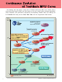
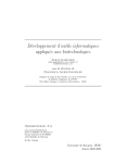
Toshiba offers a computer-on-silicon (COS) solution to help its customers improve the time-to-market for
their new processor-based systems. The combination of Toshiba’s world-class computer and silicon
technologies provides its customers with a total solution - a partnership with Toshiba brings you not only the
performance of our hardware and software IP, but
also comprehensive services and development tool
User System
support. The COS solution allows our customers to
Applications
commit their efforts to development work.
Communications, Office equipment
AV equipment,
Home-use information appliances,
Video games, Multimedia platforms,
Set-top boxes, DVD players
Services
Customer support
Application development
Solution proposals
Documentation
Design kits
Platforms
Hardware IP: MCUs, Memory, DSP,
USB, IrDA, IEEE 1394
Software IP: Middleware functions,
embedded OSes
COS Solution
Compilers
Emulators
Simulators
Semiconductor Enablers
ASICs
Packaging
EDA tools
To meet diverse customer needs, Toshiba provides a broad range of Reduced Instruction Set Computer
(RISC) and Complex Instruction Set Computer (CISC) processors. Our RISC and CISC processors are
available either as ASIC-ready cores or as standard products. Toshiba's ASIC core portfolio includes a gallery
of 32- and 64-bit TX families of RISC cores as well as Toshiba's proprietary 16-bit CISC processor families
such as TLCS-900/H and TLCS900/L1. Also included among ASIC-ready cores are a variety of hardware and
software IP cores targeted for consumer, computer, and communications applications. All these cores give
you great flexibility in the design of advanced multimedia products.
Gateway to the COS Age – RISC/CISC ASICs from Toshiba.
2
Development Tools
Continuous Evolution of Toshiba’s MPU Cores
4
ASIC-Ready RISC Cores TX Sytem RISC TX39 Family
5
ASIC-Ready RISC Cores TX Sytem RISC TX19 Family
6
ASIC-Ready CISC Cores 900 Family
7
RISC ASIC
8
CISC ASIC
9
IP Core Lines
10
Hardware / Software Co-verification Environment
11
Development Flow
12
Test Methodologies
13
Software Development Tools for RISC ASICs
14
Software Development Tools for CSIC ASICs
16
Toshiba ASIC Road Map
17
Packaging
18
Toshiba Documents
19
3
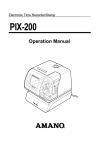
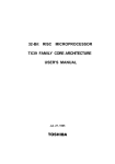
The following road map shows a whole suite of Toshiba's ASIC-ready MPU cores. Toshiba offers a
broad and varied range of RISC and CISC options to suit your unique needs, including applications,
power dissipation, and performance requirements. Encompassing Toshiba's MPU core offerings are
the TLCS-900 CISC family and the TX19, TX39, TX49, and the next-generation RISC families.
MIPS
1000
64-bit RISC processors
Addition of the MIPS-IV
instruction set
● Superscaler execution
●
●
●
●
TX79
64-bit RISC processors
Addition of the MIPS-III
instruction set
✽
TX49
32-bit RISC processors
● MIPS-I, MIPS-II, and multiply-add
operation instructions
● High-speed MAC
● On-chip debug support
●
100
●
Increased versatility
✽
TX39/H2
TX39/H
●
TX39
●
Higher-performance
version
●
Higher-performance
Lower-power
✽
32-bit RISC processors
● Addition of the MIPS 16™ASE
(reduced code size)
● Low power dissipation
●
TX19
TLCS-900/H2
10
4 performance
●✕
✽
TLCS-900/H
TLCS-900/L1
Lower-voltage version
75% power savings
● Low noise
●
2 performance
●
●✕
TLCS-900
TLCS-900/L
●
●
Lower-voltage version
50% power savings
1
ASIC-ready cores
4
✽: In Development
❈ MIPS16 is a trademark of MIPS Technologies, Inc.
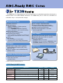
The TX39 family is a high-performance 32-bit microprocessor for embedded applications developed by
Toshiba based on the MIPS R3000A architecture. The TX39 family can be used as a foundation for
embedded array or cell-based ASIC designs.
Microprocessor Core
Development Tool Support
● R3000A architecture
● High-performance:
● C/C++ compiler, assemblers/linkers
● External real-time debug system support
TX39/H: 74 MIPS (at 70 MHz operation)
TX39/H2 (in development):
105 MIPS (at 100 MHz operation)
based on Dhrystone 2.1 VAX-11/780 benchmarking
● Built-in
Provides for real-time debug with caches enabled.
● Support
of various real-time OSes
board applicable to evaluation
and user application
● Standard
cache memory
Separate instruction and data caches
● Non-blocking
ASIC Support
load function
Avoids performance degradation by executing the
next instruction while the data cache is being
refilled.
● DSP
function
One-cycle Multiply-Accumulate (MAC)
supporting 32-bit ✕ 32-bit multiply-add operations
● Proven
EDA environment with RTL Verilog models
add-ons provided as megacells
● MPU core availability:
● Peripherals
GR39WAD: TX39/H core (TC220)
PTX3904A: Functionally-equivalent to TMPR3904A (TC220)
■ PTX39WAD: TX39/H2 core (TC240, in development)
■
■
Low Power
● Multiple
power saving modes of operation,
including Reduced-Frequency (RF), Doze,
Halt modes, etc.
● The PLL oscillation can be halted externally
(standby mode)
Applications
Set-top boxes
Vehicle navigation systems
Functions for Embedded Applications
● Improved
code density and performance
Branch-likely instructions
Hardware interlock
Personal information communicators (PIC)
❈ R3000A is a trademark of MIPS Technologies, Inc.
■ TX39 Family ASSP Products
Product Number
Applications
Clock
Frequency
Voltage
Package
TMPR3901AF-70
Standard MPU
70 MHz
3.3 V
QFP160
TMPR3903AF
Vehicle navigation systems
40 MHz
3.3 V
QFP208
66 MHz
3.3 V
QFP208
66 MHz
3.3 V
QFP208
92 MHz
3.3 V
LQFP208 / FBGA217
TMPR3904AF-66✽ Peripherals added to the standard MPU
TMPR3907F
Peripherals and a PCI controller added to the standard MPU
TMPR3912AU/XB Personal information communicators (PIC)
TMPR3922AU/XB Personal information communicators (PIC)
✽: In Development
I / O: 3.3 V
129/148 ✽ MHz Core: 2.7 V LQFP208 / FBGA217
5
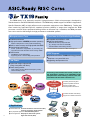
The TX19 family is an extremely compact, high-performance 32-bit microprocessor developed by
Toshiba based on the MIPS R3000A architecture. The TX19 family added support for MIPS16™ ApplicationSpecific Extension (ASE), a highly efficient code compression mechanism, to the TX39 family. Toshiba has
been introducing application-specific standard products (ASSPs) in stages that integrate the TX19
processor core and various peripheral building blocks on the same chip. In addition, the TX19 processor
core can be used in ASIC designs for high-performance embedded systems.
Microprocessor Core
Functions for Embedded Applications
● R3000A
architecture
● High-performance: 42 MIPS (at 40 MHz operation)
based on Dhrystone 2.1 VAX-11/780 benchmarking
● Built-in
cache memory and high-speed data RAM
load function
with MIPS16™ ASE
● Real-time performance
● Compatible
Minimizes an interrupt response time
(e.g. through one-clock-access RAM)
Instruction/data cache locking function
● Non-blocking
Avoids performance degradation by executing the
next instruction while the data cache is being refilled.
● DSP
function
Fast Multiply-Accumulate (MAC)
supporting 32-bit ✕ 32-bit multiply-add operations
❈ R3000A and MIPS16 are trademarks of MIPS Technologies, Inc.
ASIC Support
● Implemented
with the TC240 technology process
a very small die area
● Upgrading development tools
● Requires
Low Power
● Optimized
design implemented
using a low-power cell library
● Power saving modes
Clock gearing function (Reduced-Frequency mode)
Various standby modes
Intermixing 16-and 32-bit instructions provides all
the performance benefits of an embedded 32-bit
microprocessor while offering reduced code size
associated with the 16-bit instruction set.
Improved
density
Suitable
for
embedded
applications
CPU Core
Fast
32-bit
instruction
code
CPU core
Built-in
Switched
by
an instruction
16-bit
instruction
code
Provides performance gains.
Object-compatible with TX39.
Supports multiply-add
and coprocessor instructions.
Provides excellent code density.
Supports PC-relative instructions.
response
■ Applications
4215/MRP
6
● Handheld devices: Personal information communicators (PIC),
electronic organizers, digital cellulars
● PC peripheral equipment: HDD, DVD-ROM, printers
● Home appliances: DVD players, DVC-based systems,
digital still cameras (DSC)
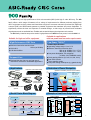
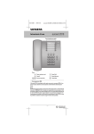
The 900 family is a high-performance 16-bit microcontroller (MCU) with high C code efficiency. The 900
family offers a wide range of features to fit a variety of requirements for different products ranging from
office equipment such as printers and facsimiles to high-end consumer electronic products like digital still
cameras (DSC) and DVC-based systems to portable equipment that mandates low power dissipation. To
significantly reduce the time and expense of controller design, a wide range of powerful and consistent
development tools are available from Toshiba and several third-party development tool vendors.
The 900 family contains two product series: high-performance 900/H and low-power, low-noise 900 /L1.
Suitable for applications
with low-power and low-noise requirements
Suitable for high-end office equipment
Low Power (900/L1)
High-Performance CISC Core
● Minimum
instruction execution time:
160 ns (at 25 MHz)
● 32-bit ALU
● 4-bit barrel shifter
Compact Core
● Reduced
die size due to a very lean set of
instructions selected for embedded applications
■ Applications
Tentative Specifications
● Operating voltage range: 1.8 to 5.5 V
● Minimum instruction execution time:
250 ns (at 16 MHz, Vcc ≥ 2.7 V)
400 ns (at 10 MHz, Vcc ≥ 1.8 V)
● Low power dissipation: 3.0 mA typical
(16 MHz, 3.0V, NORMAL mode)
● Clock gearing function: (fc, fc/2, fc/4, fc8, fc/16)
● Dual clock function
● Three standby modes
● Low-power design techniques (e.g. gated clocks)
■ Reduction of Power Dissipation
Electronic musical instruments
Printers
(Relative to Toshiba's previous microcontrollers)
Icc
(mA)
19 mA
HDD
Digital still cameras
GXT-8500
0.6 µm
Approx.
20
CD-ROM drives
Conditions: 95CW64 equivalent
ROM: 128 Kbytes
RAM: 4 Kbytes
3 V, 16 MHz, 25˚C
900 / H
Approx.
15
Cellular phones
(mobile phones)
..........
6 mA
900 / L1
10
3 mA
0.6 µm
900 / L1
Digital-video-cassette-based
systems
0.4 µm
5
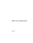
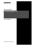
■ Serial Printer Block Diagram
■ Examples of Low-Power Design Techniques
Host Computer
Before
RAM and ROM
900/L1
Decoder
Interface
Paper Sensor
MCU
Address Bus
Display LED
SIO
L
900/H Series
Carriage
Detection
Gate Array
H
L
Decoder
Operation Switches
Control
Logic
Data Bus
Memory
Gated-Clock Logic
H
L
Motor Driver
INTC
Decoder
Decoder
Head Driver
Head
Timer
Precharge
Signal
Precharge
Signal
Clock
The enabling and disabling
of the clock can be controlled
via this signal.
7
■ RISC ASIC Configurations
RISC ASIC
G-Bus
Instruction Cache
Data Cache
DSU
(
)
Debug
Support
Unit
WBU (
)
Write
Buffer
Unit
APU
(
G-Bus Interface
CPU Core
Memory,
High-Speed
Peripheral
(e.g. DMAC)
External
Bus Interface
IM-Bus Bridge
MPU ASIC Core
IM-Bus
Low-Speed
Peripheral
(e.g. Timer)
)
Address
Protection
Unit
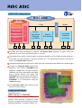
The RISC ASIC allows designers to integrate a TX System RISC megacell (or system CPU) with
peripheral IP cores and/or user-defined logic on one chip.
The integral G-bus directly connects system components together, such as a DMA controller acting as a
bus master, a memory controller, a interrupt controller, etc. The specification of G-bus is provided to
users of a TX System RISC megacell.
Low-speed peripherals like a timer and a UART block are connected through IM-Bus via a bridging logic.
Currently, the TX System RISC megacells are
available in two versions: GR39WAD which
integrates a TX39 CPU core with a Address
Protection Unit (APU), Write Buffer Unit (WBU),
and a Debug Support Unit (DSU) and
PTX3904A which is functionally equivalent to
TX3904A. The high-performance megacell,
PTX39WAD, is in development using the
TC240 technology.
The TX39-based ASIC chip requires a package with at least 160 pins.
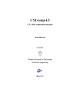
■ Application Example
Digital BS Receiver
MPEG-2 Decoder IC: TC81220F
Toshiba's TC81220F integrates a TX39 core, a
MPEG-2 video decoder, a MPEG-1/2 audio
decoder, a programmable transport processor,
standard peripherals, a memory controller, etc.
8
Photo of the TC81220F
■ CISC ASIC Configurations
CISC ASIC
MPU ASIC Core
TLCS-900/H ASIC Bus
CPU Core
Chip Select /
Wait Controller
Memory
Peripheral
User-Defined
Logic
Interrupt Controller
The CISC ASIC offers a megacell, SMC95C001, which integrates a 900/H core with such built-in
functions as a chip-select/wait controller and an interrupt controller. The SMC95C001 is functionally
equivalent to Toshiba's standard product TMP95C001.
The TLCS-900/H Bus, which is the standard bus specification for all 900/H products, connects the 900/H
core with memories (RAMs, ROMs, etc.), peripheral I/O functions, and user-defined logic.
The TLCS-900/H Bus is routed off-chip, so the same emulator can be used to test both the standard
TMP95C001 product and 900/H core-based ASICs.
■ Application Example
Toshiba used its CISC ASIC solution to integrate
a 900/H core with ROM, RAM, standard
peripherals, and A/D converters to build a
communications IC. This IC is fabricated using
the TC222C technology. While the I/O interfaces
with 3 V, the core operates at 2 V, reducing
power dissipation.
Communications IC Implemented as a CISC-Processor-Core-Based ASIC
9
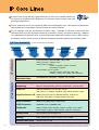
A broad range of high-density, high-performance IP cores is an essential element for
the success of advanced ASIC designs for all consumer, communications, and data
processing applications.
For true systems-on-a-chip, the supporting ASIC silicon technologies cover a full spectrum of application
requirements with a wide range of power, density, and speed solutions.
IP core offerings meet the requirements of system chips. Hardware IP libraries include cores that
implement RISC and CISC processors as well as multimedia, network, and protocol functions. Software
(or synthesizable) IP libraries include cores that implement middleware functions such as JPEG, speech
processing, and fax modem as well as real-time embedded operating systems and software drivers.
■ IP Core Availability
Hardware
Software
DRAM,
Flash Memory
10
(Cores in development are included.)
Microcomputers,
ASICs
System Chips
(ASSPs)
Toshiba's
Electronic Equipment
Divisions
System Chips
Third-Party
Portable
IP Cores
Middleware
Image processing MH / MR / MMR, JBIG, JPEG
Audio processing ADPCM, CELP
Human-machine interface
Speech recognition, Speech synthesis,
Handwriting recognition
Communication and PC interface
Software modems, IEEE1394, USB, IrDA,
PCMCIA, TCP/IP, PPP, SNMP, DOS filesystem
Real-time
Embedded OSes
µITRON/UDEOS, pSOSystem®, Windows® CE, Tornado™
Multimedia
JPEG core, MPEG-2 decoder, NTSC/PAL video encoder, MPEG-4 core
Networking
Ethernet 10/100 MHz MAC, Ethernet 100 MHz PHY, 155 MHz CDR
Protocols
IEEE1394, IEEE1284, PCI controller, TCP/IP,
USB, IrDA (V1.1), PCMCIA, CardBUS, AGP, SSFDC interface, ATAPI
High-Performance I/O 622MHz SCI-LVDS, SSTL-3 (SDRAM interface), 66 MHz PCI,
USB, AGP, Direct RAC (1.6 GBps Rambus™ASIC cell)
RISC Processors
TX49 (64-bit), TX39 (32-bit), TX19 (32-bit),
CISC Processors
TLCS-900 (16-bit), TLCS-Z80 (8-bit)
Peripherals
DRAM controller, ROM controller, Interrupt controller, Timer, DMAC,
Serial interface (UART), Parallel interface, External bus interface
Analog Cores
A/D converters, D/A converters, PLL
Memory
DRAM, SRAM, FIFO, ROM, E PROM, Flash E PROM
Standard ASIC Cells
Primitive cells, I/O cells
2
2
✽ Company names and product names may be trademarks or registered trademarks by their respective companies.
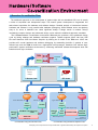
■ Seamless Co-verification Flow
The traditional approach to the development of system chips with an embedded CPU core is usually
a series of sequential and independent steps. This means system development is fragmented into
task-oriented specialties like hardware and software designs. Detailed analysis of interactions between
hardware and software is only possible after hardware prototyping. While software errors are relatively
easy to fix, errors in hardware can cause significant delays if design rework is needed. Today's
increasingly complex designs and shortened design cycles make the traditional approach unsuitable.
The hardware/software co-verification environment addresses the problems of the traditional design
cycle by linking software and hardware verification together. Toshiba supports ASVP Lab from CAE
Plus and Seamless CVE from Mentor Graphics by offering the C model of the TX39 core. ASVP Lab
provides all-C model hardware and software debugging by assembling ArchGen C models of userdefined logic and the TX39 C model into a high-speed virtual prototype. Seamless CVE delivers highperformance system verification environment by combining embedded software development tools with
behavioral and logic simulation.
TX39
Peripheral
Logic
Memory
System Development
Software Implementation
Hardware Implementation
int caller (int Pl)
{
int total;
total=Pl;
.
.
.
always@(DATA) begin
F=0;
F[DATA]=l'bl;
end
.
.
.
C Source Code
RTL Code
Software
Hardware
Software
Hardware
C Source
Data Flow
C Source
RTL Code
Green Hills Software, Inc.
CAE Plus, Inc.
C/C++
Compiler
Cygnus Solutions
C/C++
Compiler
ArchGen
Mentor Graphics Corp.
Debugger
®
MULTI
TX39 Model
Peripheral Logic
Model
ASVP Lab
Green Hills
Software, Inc.
CAE Plus, Inc.
Co-verification Using the CAE Plus Tools
Debugger
®
XRAY
TX39
Model
Mentor Graphics Corp.
Seamless CVE
Verilog-XL
ModelSim
Cadence Design
Systems, Inc.
Mentor Graphics Corp.
Co-verification Using the Mentor Graphics Tools
✽ Company names and product names may be trademarks or registered trademarks by their respective companies.
11
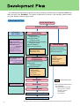
The following flowchart shows a typical process for developing an ASIC with an integrated TX39 family
RISC processor core, GR39WAD. For support of EDA tools not shown in the flowchart, please contact
your local Toshiba customer support group.
■ Development Flow
System Specification
Hardware and Software Partitioning
Deliverables
from Toshiba
System Design
● Hardware
■
■
ASIC documentation set
TX39 User's Manual
■
TX39 Programming Guide
■
GR39WAD Megacell
Specification
■
IP core specifications
Megacell RTL library
■
■
Megacell test vector set
design
Verilog RTL coding
● Test logic insertion
Verilog RTL coding
● Verification environment modeling
Verilog RTL coding
✦
● System simulation
● Test vector development
Cadence Verilog-XL
■ Megacell RTL library
■ Megacell test vectors
Software Design
● System
software design
■
● Applications
● Prototype
software design
board test
C/C++ compiler
Debugger
■ TX39 standard board
■ Processor probe
■ ROM emulator
■ Real-time operating system
■
■
■
■
■
VSO megacell models
ASIC libraries
Verilog-XL Sign-Off (VSO)
System software
Logic Synthesis
and Optimization
● Synthesis
parameter tuning
sizing✦/
Critical path extraction✦
✦
● Gate-level simulation
● Array
Synopsys
Design Compiler
and Design Analyzer
■ ASIC libraries
■ VSO megacell models
■
First Signoff
Back-annotation files
derived from chip layout
Resimulation
Second Signoff
Wafer Personalization and Testing
Tools and libraries used
✦: Recommended hardware platform
Sun UltraSPARC
with LAN interface or equivalent
Main memory: 512 Kbytes
Hard disk: 3 Gbytes
CD-ROM drive
Tape streamer
Engineering Sample Shipment
12
✽ Company names and product names may be trademarks or registered trademarks by their respective companies.
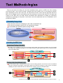
There are two issues for testing of a chip with embedded blocks such as an MPU core. One is testing
of the block itself. In the case of a large, complex block like an MPU core, it is necessary to test the
block separately from the rest of the chip. The figure below shows a direct access approach where the
MPU core is isolated from the user-defined logic by providing an access collar around it. All inputs and
outputs of the MPU core are made directly accessible and observable for testing by connecting
multiplexers to package pin test points. A test vector set for the stand-alone test of an embedded core is
provided by Toshiba.
■ Testability Design Flow
Test structures need to be designed as part of the user-defined logic.
Test structure examples coded at RTL are provided by Toshiba.
An automated test synthesis system is being planned.
Toshiba
Users
Testability Design Package
● Test structure guidebook
● Test structure examples (Verilog
● MPU test vector set
● Testability design
● Signoff simulation
(First signoff, Second signoff)
RTL coding)
● Netlist / Test vector
● List of I/O pin assignment
for MPU testing
■ Isolating the MPU Core
Stand-alone Testing of the MPU
The MPU core is isolated from the rest of the design during testing. Test vectors for the MPU core are provided
by Toshiba and multiplexed through a set of I/O pins. The flow of data while the MPU core is tested is shown
by the bold paths below.
R I SC / CISC ASIC
User Logic
MUX
Peripheral
MUX
CPU Core
MPU ASIC Core
Testing of the User-Defined Logic
The user-defined logic is isolated from the MPU core for testing purposes. Test vectors for the user-defined
logic are created by the designer, and internal signals are routed as necessary to ASIC I/O pins to improve
testability. The flow of data while the user-defined logic is tested is shown by bold paths below.
R I SC / CISC ASIC
User Logic
MUX
Peripheral
MUX
CPU Core
MPU ASIC Core
✽ Company names and product names may be trademarks or registered trademarks by their respective companies.
13
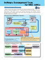
■ Software Development Environment
Exactly the same suite of tools are supported for the software development of RISC
ASICs as for standard TX family products. To significantly reduce the time and expense of processorbased design, a wide range of powerful and consistent development tools, including compilers,
debuggers, real-time operating systems, and processor probes, are available from Toshiba and several
third-party development tool vendors.
Processor Probe / ROM Emulator Connection
■ Emulation Solution
or ROM Emulator
X Windows System
Ethernet
Windows® 95 / NT
✽2
■ GHS Language Tools
✽1
■ Cygnus Solutions
PC
(IBM-PC)
GNU Language Tools
EWS
(Sun, HP)
■ Real-time OS
µITRON
C Executive
● Tornado
● pSOSystem
●
Real-time Debug Support System
Target Board
●
TX39 ASIC
TX39 Core
Memory
User-Defined
Logic
8
Debug Support
Unit (DSU)
4 kgates (DSU) + 8 dedicated pins ✽ 3
✽1 Only PCs are supported as a host of the ROM emulator.
✽2 The ROM emulator can operate
over a dedicated RS232C parallel interface.
✽3 TX39/H2 (in development): 10 pins for debugging
The DSU is built into the TX39 core, and permits monitoring of the internal
TX39 core state provided its eight debug pins are routed to ASIC I/O. This
results in debug break exceptions or triggers, enabling the use of generalpurpose real-time debuggers for TX39-core-based ASIC development.
Third-Party Development Tools for TX39
14
Real-time OS
Language Tools
Debuggers
Wind River Systems, Inc.
Cygnus Solutions
Cygnus Solutions
Tornado™
GNU C/C++gcc
Emulators
DENSAN Systems, Inc.
DVE-R3900
DVE-R3904/20
GNU Debugger
Green Hills Software, Inc.
Green Hills Software, Inc.
Hewlett-Packard Company
C/C++ Compiler
MULTI®
E5900A, E5901A
E5902A, E5903A
Integrated Systems, Inc.
Integrated Systems, Inc.
(Green Hills Software + MULTI [1.8.7C])
pSOSystem®
pRISM+
Monitors / Evaluation Boards
Lightwell Co., Ltd.
MDX700
✽ Company names and product names may be trademarks or registered trademarks by their respective companies.
■ Third-Party Development Tools
TX39
Vendor
Tool
Product Name
Green Hills Software, Inc.
Language Tool
Debugger
C/C++ CROSS MIPS COMPILER
MULTI ®
Integrated Systems, Inc.
Real-time OS
pSOSystem®
Wind River Systems, Inc.
Real-time OS
Tornado™
DENSAN Systems, Inc.
Evaluation Board
DVE-R3904 / 20
DVE-R3900 / 20A
DVE-R3900 / 20
Cygnus Solutions
Language Tool
Debugger
GNU Pro™ Tool kit
GDB
Hewlett-Packard Company
Processor Probe
HPE3492B
Vendor
Tool
Product Name
Green Hills Software, Inc.
Language Tool
Debugger
C/C++ CROSS MIPS COMPILER
MULTI®
Integrated Systems, Inc.
Real-time OS
pSOSystem®
Cygnus Solutions
Language Tool
Debugger
GNU Pro™ Tool kit
GDB
Hewlett-Packard Company
Processor Probe
HP Distributed Emulation System
Yokogawa Digital Computer
In-circuit Emulator
IDB Analyzer
TX19 (Under Development)
✽ Company names and product names may be trademarks or registered trademarks by their respective companies.
15
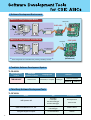
■ Software Development Environment
Method 1: Using an Adaptor Board
QFP Probe
CISC ASIC
Emulation Pod
C Compiler OS
PC or EWS
MCU Emulator
Adaptor Board
Target Board
Method 2: Using an ASIC on the Board
CISC ASIC
Connector
Emulation Pod
C Compiler OS
PC or EWS
MCU Emulator
Target Board
(Breadboard)
Same configuration as for standard CISC products (provided by Toshiba)
■ Toshiba's Software Development System
TLCS-900/H
Supported MCU
Product
Embedded
Software Controller
Language Tool
TMP95C001F
Real-time OS
Assembler, C Compiler
Test Tool
Real-time Emulator
Debugger
model 25
model 15
Note: For details, please consult the Microcomputer DEVEOPMENT SYSTEM GUIDE brochure.
■ Third-Party Software Development Tools
TLCS-900/H
Vendor
Tool
IAR Systems AB
Assembler
C Compiler
Simulator Debugger
Emulator Debugger
GAIO TECHNOLOGY Co., Ltd.
C Compiler
ICE Debugger
XASS-V Series
Yokogawa Digital Computer
In-circuit Emulator
ADViCE
Product Name
Development kit
C-SPY/S 900
✽ Company names and product names may be trademarks or registered trademarks by their respective companies.
16
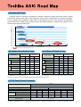
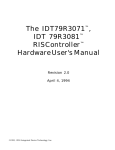
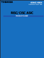
■ Toshiba ASIC Trend
Relative Power Dissipation (vs. TC160G/E at 5.0 V)
In keeping with our overriding commitment to meeting customers' present and future needs, Toshiba
continuously pursues new goals in the exploration of both silicon technologies and design techniques.
For true system-scale integrations, ASIC silicon technologies must cover a full spectrum of application
requirements with a broad range of power, density and speed solutions, complete with support of core
functions and high-performance I/O.
1
TC160G / E
High-Performance and Low-Power ASIC Solutions
5V
0.9
0.8
5V
TC170G / C
0.7
5V
0.6
TC190G / C
0.5
3.3 V
0.4
TC180G / C / E
0.3
3.3 V
TC200G / C / E
0.2
3.3 V
0.1
2.5 V
TC220G / C / E
2V
TC240C / E
TC222C
40 M
80 M
60 M
100 M
Performance (Hz)
: Supports embedded RISC/CISC cores.
■ Embedded Array Product Lines
I/O: 3.3 V
Core: 3.3 V
Product Family
120 M
140 M
■ Cell-Based IC Product Lines
I/O: Mixed 3.3/5 V
Core: 3.3 V
0.3 µm
Delay Fanout = 1
Time★ Fanout = 2
+ typical interconnect
Usable Random Gates
I/O
Pads
0.11 ns
0.15 ns
0.19 ns
0.15 ns
0.19 ns
704 k
512
193 k
0.4 µm
0.3 µm
0.4 µm
0.10 ns
0.06 ns
0.10 ns
0.14 ns
0.17 ns
0.14 ns
0.17 ns
2.1 M
729 k
2.1 M
718 k
Wirebond
512
512
504
504
TAB
768
768
768
768
0.41 µW
0.91 µW
0.41 µW
0.91 µW
0.24 µW
0.48 µW
0.24 µW
0.48 µW
40
39
40
38
Delay Fanout = 1
Time★ Fanout = 2
+ typical interconnect
Usable Random Gates
694 k
504
0.3 µm
0.06 ns
Process
0.07 ns
I/O
Pads
504
768
776
768
768
Power Dissipation★★
0.65 µW
1.14 µW
0.65 µW
1.14 µW
Masterslices
38
39
40
38
I/O: Mixed 3.3/5 V
Core: 3.3 V
TC220C TC200C TC223C TC203C
0.4 µm
0.11 ns
512
TAB
0.3 µm
0.07 ns
1.9 M
Wirebond
0.4 µm
I/O: 3.3 V
Core: 3.3 V
Product Family
TC220E TC200E TC223E TC203E
Process
160 M
Power
ND2 (Fanout = 1)
Dissipation★★ ND2R (Fanout = 1)
Masterslices
★: High-drive 2-input NAND gate
★★: µW/gate/MHz (3.3 or 5 V), 2-input NAND, fanout = 1
★: High-drive 2-input NAND gate
★★: µW/gate/MHz (2, 3.3, or 5 V), ND2: 2-input NAND, NR2R: Low-power 2-input NAND
Note: The above tables give only the product families supporting embedded RISC and CISC cores.
■ TC240 Family Product Summary
0.25 µm
Process Technology
HC2MOS Si-gate five layer metal
Series
Embedded Arrays
Cell-Based IC
Maximum Usable Gates★ (with four metals)
8.8 Mgates
10.2 Mgates
★★
Cell Name
Delay Time (ps)
GND2X1
GND2X2
GND2X4
CND2XL
CND2X1
CND2X2
CND2X4
Fanout = 1
77
68
61
87
70
55
54
Fanout = 1 + typical interconnect
141
101
79
218
118
83
68
0.156
0.270
0.487
0.107
0.170
0.296
0.563
Power Dissipation (µW/MHz, Fanout = 1)
Core: 2.5 V
I/O: 2.5 V/3.3 V
Operating Voltage
★: Depends on design configurations.
★★: ❑ND2X1: 2-input NAND gate, ✕1 drive
❑ND2X2: 2-input NAND gate, ✕2 drive
❑ND2X4: 2-input NAND gate, ✕4 drive
❑ND2XL: 2-input NAND gate, ✕1/2 drive
17
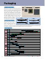
■ High-Density Packages
144 Pins
FBGA
0.8 mm-pitch
BGAs provide the highest I/O-to-body-size ratio, with solder
balls formed on the bottom in an area array format and a ball
pitch of 1.27 or 0.8 mm. In spite of increased ball pitches,
BGAs result in smaller footprints than PQFPs. The photo at right
shows an FBGA and a TBGA, in contrast to PQFPs with the
same lead counts. Formally known as chip scale packages
(CSPs), the fine-pitch BGA (FBGA) is generally defined as
having a package body size no larger than 1.2 times the die
size. Tape BGA (TBGA) packages support ultra-high pin count
applications. TBGAs combine the fine die pad pitch
interconnect advantages of TAB with the assembly ease of
BGAs. The center balls of the TBGA is
PQFP
depopulated to allow room for the face44 – 304 pins
down TAB bonded and encapsulated die.
304 Pins
PQFP
0.5 mm-pitch
TBGA
1.27 mm-pitch
PQFP
0.5 mm-pitch
LQFP
48 – 208 pins
4.45 mm
1.6 mm
■ Thin and Light Packages
TBGA
TQFP
256 – 576 (840) pins
LQFP and TQFP packages provide a thin,
64 – 128 (176) pins
1.4 mm
lightweight surface mount solution to
1.2 mm
system miniaturization. The package
Packages with lead counts shown in parentheses are under development.
height is 1.4 mm (seating height = 1.6
mm) for the LQFP lines and 1.0 mm
(seating height = 1.2 mm) for the ultra-thin TQFP lines. Also, TBGAs support both the low-profile and ultra-high-pin-count requirements. With
their excellent heat dissipation, low profile, and low cost, TBGAs can handle a wide variety of applications.
■ Lead Count Chart
Package
Family
# I/O
Lead Pitch
100
200
300
256
1.27 mm
TBGA
400
304
352
336
1.0 mm
1.5 –
1.27 mm
PFBGA
(CSP)
0.8 mm
LQFP
0.4 mm
LQFP
[Cu]
TQFP
225
177
48 64 80 100
64
0.5 mm
0.5 mm
0.5 mm
144
100
176
241
44 60 R80 100
144
216
256
184
176
208
240
208
160
240 256
304
184
208
240
296
100
120
144 160
184
176
208
240
304
240
304
160
208
0.5 mm
2.54 mm
304
208
160
0.5 mm
2.54 mm
64 69 85 101
121
145
181
155
225
223
299
1.27 mm
Not all die sizes are available with all packaging options. When your need for an ASIC arises,
please contact the nearest ASIC service group.
18
337
176
144 160
100
0.65 mm
CPGA
305
120
R100
0.65 mm
CPGA
[CD]
301
273
208
0.4 mm
CQFP
[A N]
840
R64
0.5 mm
0.8 mm
768
720
144
144
0.65 mm
CQFP
648
620
120 128
PQFP
0.65 –
[Cu]
0.5 mm
PQFP
0.5 –
[TAB/Cu]
0.4 mm
HQFP
560
520
64 80 100
0.4 mm
0.65 mm
900
144
176
0.5 mm
0.8 mm
800
176
0.4 mm
1.0 mm
PQFP
120
128
0.4 mm
TQFP
[Cu]
100
144
209
700
256
141 145 169 177 181 201 205 217 241
85 97 109
600
576
480
432
0.5 mm
0.5 mm
480
400
0.8 mm
PBGA
500
420
391
: Available
: In Development
: Planned
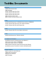
■ Brochures
● CMOS ASICs Product Guide
● ASIC Packaging
● 32-Bit TX System RISC TX19 Family
● 32-Bit TX System RISC TX39 Family
● 64-Bit TX System RISC TX49 Family
● Microcomputers Product Guide
● Microcomputer Development System Guide
■ TX39
● 32-Bit RISC Microprocessor TLCS-R3900 Family (Architecture TMPR3901F)
● 32-Bit TX System RISC TX39 Family User's Manual (Hardware)
● 32-Bit TX System RISC TX39 ASIC Design Guide
■ TX19
● 32-Bit TX System RISC TX19 User's Manual (Architecture)
■ TX49
● 64-Bit RISC Microprocessor TX49 User's Manual
■ TLCS-900/H and TLCS-900/L1
● 16-Bit Microcontroller TLCS-900/H Series User's Manual (1)
● Development System Manual (ASSEMBLER)
● Development System Manual (C COMPILER)
● Microcomputer Development System Real-time OS (User's Manual)
● 16-Bit Microcontroller TLCS-900/H, TLCS-900/L APPLICATION NOTE
■ Design Handbooks
● User's manuals for various EDA tools
● CMOS ASIC Design Manual
● Design-for-Test Handbook
● ASIC Packaging
19
OVERSEAS SUBSIDIARIES AND AFFILIATES
Toshiba America
Electronic Components, Inc.
Toshiba Electronics Europe GmbH
Headquarters-Irvine, CA
9775 Toledo Way, Irvine, CA 92618, U.S.A.
Tel: (949)455-2000 Fax: (949)859-3963
Hansaallee 181, D-40549 Düsseldorf
Germany
Tel: (0211)5296-0 Fax: (0211)5296-400
Boulder, CO
München Office
3100 Arapahoe Avenue, Ste. 500,
Boulder, CO 80303, U.S.A.
Tel: (303)442-3801 Fax: (303)442-7216
Büro München Hofmannstrasse 52,
D-81378, München, Germany
Tel: (089)748595-0 Fax: (089)748595-42
Boynton Beach, FL(Orlando)
Toshiba Electronics France SARL
11924 W. Forest Hill Blvd., Ste. 22-337,
Boynton Beach, FL 33414, U.S.A.
Tel: (561)374-6193 Fax: (561)374-6194
Immeuble Robert Schumann 3 Rue de Rome,
F-93561, Rosny-Sous-Bois, Cedex, France
Tel: (1)48-12-48-12 Fax: (1)48-94-51-15
Deerfield, IL(Chicago)
Toshiba Electronics Italiana S.R.L.
One Pkwy., North, Suite 500, Deerfield,
IL 60015-2547, U.S.A.
Tel: (847)945-1500 Fax: (847)945-1044
Centro Direzionale Colleoni
Palazzo Perseo Ingr. 2-Piano 6,
Via Paracelso n.12,
1-20041 Agrate Brianza Milan, Italy
Tel: (039)68701 Fax:(039)6870205
Duluth, GA(Atlanta)
3700 Crestwood Parkway, Ste. 460,
Duluth, GA 30096, U.S.A.
Tel: (770)931-3363 Fax: (770)931-7602
Edison, NJ
2035 Lincoln Hwy. Ste. #3000, Edison
NJ 08817, U.S.A.
Tel: (732)248-8070 Fax: (732)248-8030
Orange County, CA
2 Venture Plaza, #500 Irvine, CA 92618, U.S.A.
Tel: (949)453-0224 Fax: (949)453-0125
Portland, OR
1700 NW 167th Place, #240,
Beaverton, OR 97006, U.S.A.
Tel: (503)629-0818 Fax: (503)629-0827
Richardson, TX(Dallas)
777 East Campbell Rd., Suite 650, Richardson,
TX 75081, U.S.A.
Tel: (972)480-0470 Fax: (972)235-4114
San Jose Engineering Center, CA
1060 Rincon Circle, San Jose, CA 95131, U.S.A.
Tel: (408)526-2400 Fax:(408)526-2410
Wakefield, MA(Boston)
401 Edgewater Place, Suite #360, Wakefield,
MA 01880-6229, U.S.A.
Tel: (781)224-0074 Fax: (781)224-1095
Düsseldorf Head Office
Toshiba Electronics España, S.A.
Parque Empresarial San Fernando Edificio Europa,
a
1 Planta, ES-28831 Madrid, Spain
Tel: (91)660-6700 Fax:(91)660-6799
Toshiba Electronics(UK) Limited
Riverside Way, Camberley Surrey,
GU15 3YA, U.K.
Tel: (01276)69-4600 Fax: (01276)69-4800
Toshiba Electronics Scandinavia AB
Gustavslundsvägen 12, 2nd Floor
S-161 15 Bromma, Sweden
Tel: (08)704-0900 Fax: (08)80-8459
Toshiba Electronics Asia
(Singapore) Pte. Ltd.
Singapore Head Office
438B Alexandra Road, #06-08/12 Alexandra
Technopark, Singapore 119968
Tel: (278)5252 Fax: (271)5155, (270)6056
Bangkok Office
135 Moo 5 Bangkadi Industrial Park, Tivanon Rd.,
Bangkadi Amphur Muang Pathumthani, Bangkok,
12000, Thailand
Tel: (02)501-1635 Fax: (02)501-1638
Toshiba Electronics Trading
(Malaysia)Sdn. Bhd.
Kuala Lumpur Head Office
Suite W1203, Wisma Consplant, No.2,
Jalan SS 16/4, Subang Jaya, 47500 Petaling Jaya,
Selangor Darul Ehsan, Malaysia
Tel: (3)731-6311 Fax: (3)731-6307
Penang Office
Suite 13-1, 13th Floor, Menard Penang Garden,
42-A, Jalan Sultan Ahmad Shah,
100 50 Penang, Malaysia
Tel: 4-226-8523 Fax: 4-226-8515
990426(B)
Toshiba Electronics Philippines, Inc.
26th Floor, Citibank Tower, Valero Street, Makati,
Manila, Philippines
Tel: (02)750-5510 Fax: (02)750-5511
Toshiba Electronics Asia, Ltd.
Hong Kong Head Office
Level 11, Top Glory Insurance Building, Grand Century
Place, No.193, Prince Edward Road West,
Mong Kok, Kowloon, Hong Kong
Tel: 2375-6111 Fax: 2375-0969
Beijing Office
Rm 714, Beijing Fortune Building,
No.5 Dong San Huan Bei-Lu, Chao Yang District,
Beijing, 100004, China
Tel: (010)6590-8795 Fax: (010)6590-8791
Chengdu Office
Unit F, 18th Floor, New Times Plaza, 42 Wenwu Road,
Xinhua Avenue, Chengdu, 610017, China
Tel: (028)675-1773 Fax: (028)675-1065
Shenzhen Office
Rm 3010-3012, Office Tower Shun Hing Square,
Di Wang Commercial Centre, 333 ShenNan
East Road, Shenzhen, 518008, China
Tel: (0755)246-1582 Fax: (0755)246-1581
Toshiba Electronics Korea Corporation
Seoul Head Office
14/F, KEC B/D, 257-7 Yangjae-Dong,
Seocho-ku, Seoul, Korea
Tel: (02)589-4334 Fax: (02)589-4302
Kumi Office
6/F, Ssangyong Investment Securities B/D,
56 Songjung-Dong, Kumi City
Kyeongbuk, Korea
Tel: (82)546-456-7613 Fax: (82)546-456-7617
Toshiba Technology Development
(Shanghai) Co., Ltd.
23F, Shanghai Senmao International Building, 101
Yin Cheng East Road, Pudong New Area, Shanghai,
200120, China
Tel: (021)6841-0666 Fax: (021)6841-5002
Tsurong Xiamen Xiangyu Trading
Co., Ltd.
8N, Xiamen SEZ Bonded Goods Market Building,
Xiamen, Fujian, 361006, China
Tel: (0592)562-3798 Fax: (0592)562-3799
Toshiba Electronics Taiwan
Corporation
Taipei Head Office
17F, Union Enterprise Plaza Bldg. 109
Min Sheng East Rd., Section 3, 0446 Taipei,
Taiwan R.O.C.
Tel: (02)514-9988 Fax: (02)514-7892
Kaohsiung Office
16F-A, Chung-Cheng Bldg., Chung-Cheng 3Rd.,
80027, Kaohsiung, Taiwan R.O.C.
Tel: (07)222-0826 Fax: (07)223-0046
The information contained herein is subject to change without notice.
The information contained herein is presented only as a guide for the applications of our products.
No responsibility is assumed by TOSHIBA for any infringements of patents or other rights of the third parties which may result
from its use. No license is granted by implication or otherwise under any patent or patent rights of TOSHIBA or others.
TOSHIBA is continually working to improve the quality and the reliability of its products. Nevertheless, semiconductor devices
in general can malfunction or fail due to their inherent electrical sensitivity and vulnerability to physical stress. It is the responsibility
of the buyer, when utilizing TOSHIBA products, to observe standards of safety, and to avoid situations in which a malfunction
or failure of a TOSHIBA product could cause loss of human life, bodily injury or damage to property. In developing your designs,
please ensure that TOSHIBA products are used within specified operating ranges as set forth in the most recent products
specifications. Also, please keep in mind the precautions and conditions set forth in the TOSHIBA Semiconductor Reliability
Handbook.
Electronic Devices Sales & Marketing Group
1-1, Shibaura 1-chome, Minato-ku, Tokyo, 105-8001, Japan
Tel: (03)3457-3405 Fax: (03)5444-9431
The products described in this document may include products subject to the foreign exchange and foreign trade laws.
©1999 TOSHIBA CORPORATION
Printed in Japan