1
6
MicroMini™ Controller User Manual
Front Panel Indicators
LED Status Indicators
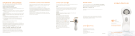
The following, from top to bottom, are the status indicators and their meaning:
•MODULE/NET
STATUS
Flashing green = not initialized/Allocated
Steady green = Initialized/Allocated
Flashing Red = Recoverable Communications Error
Steady Red = Unrecoverable Communications Error
•MOVE IN PROGRESS = Active Position or Velocity Profile
•IN POSITION = Motor is in the Commanded Position
•EMERGENCY STOP = ESTOP Input has been Activated
•POSITIVE LIMIT = PLIM Input has been activated
•NEGATIVE LIMIT = NLIM Input has been Activated
Configuration Options
Node Address (switches 5-10)
The individual node address is determined by the binary coding of these switches. Switch 5 is the least
significant bit (LSB). Node 0 = all switches RIGHT. In the Remote Mode (RS232/RS-485) all nodes will
respond to a command directed to node 0. This functionality allows synchronization among multiple
nodes. This is the reason 63 axes can be addressed serially.
Data Rate Switches
DATA RATE (3 and 4) Communication rate determined by the binary encoding of these switches as
indicated below:
Switch #
3
LEFT
RIGHT
LEFT
RIGHT
Remote Data Rate (kbaud)
4
LEFT
LEFT
RIGHT
RIGHT
RS-232C/RS485
57.6
19.2
38.4
9.6
Local/Remote Mode
Switch number 1 to RIGHT = RS-232C/RS485 mode active (default)
Switch number 1 to LEFT = Local mode (Potentiometer/joystick operated)
Isolation Power Source
The “opto power” selector determines whether or not the MicroMini™ Controller opto isolation devices
will be powered from an internal (5 VDC) or external (5 VDC) power source. The customary (default)
setting is “internal”. If an “external” power is desired, a source can be accommodated at pin 3 of the
external interface connector, J2, on the rear of the module.